AM712-S使用手册
COM712-S使用手册
系统互连模块COM712-S1基本说明COM712-S系统互连模块是将JX-300X/JX-300XP/ECS-100系统接入ECS-700系统的核心部件,是连接ECS-700控制器与JX-300X/JX-300XP/ECS-100系统I/O机笼的中间环节。
在系统架构上,COM712-S模块处于ECS-700系统的I/O连接模块层次,一方面,COM712-S 模块通过扩展I/O总线与FCU711-S控制器进行通讯;另一方面,COM712-S模块通过SBUS-S2网络与JX-300X/JX-300XP/ECS-100系统的I/O机笼进行通讯,实现控制器与I/O卡件之间的数据交互。
COM712-S模块支持冗余,一对COM712-S模块最多支持4个I/O机笼,共计64块I/O卡件。
2功能特点COM712-S模块可以冗余配置,在冗余配置状态下,任意时刻只有工作模块进行实时数据通信,备用模块通过监听保证实时数据的同步。
模块的前端面板有一组指示灯,用于指示模块的工作状态。
模块后端接有96脚的欧式插针,用于模块的供电、读取跳线地址、与I/O机笼交换数据等。
模块使用MB720-S和MB728-S型基座,基座上的地址跳线用于确定模块在扩展I/O总线上的网络地址。
COM712-S模块具备以下特点:具有硬件看门狗功能,在模块受到干扰导致软件运行异常时能自复位CPU,使系统恢复正常运行。
支持1:1冗余配置。
运行过程中如果工作侧模块出现故障,根据故障深度自动将工作权交给故障较轻的一方,切换过程对现场控制无扰动。
扩展I/O总线采用冗余的工业以太网技术。
COM712-S模块允许上位机通过故障诊断软件对模块进行故障诊断,实时监听模块运行状态。
COM712-S模块具备扩展I/O总线地址冲突检测功能和网络断线检测功能,以及模块自身运行状况检测功能。
3性能指标表 3-1性能指标项目指标一对控制器可扩展的COM712-S模块对数0~7一对COM712-S模块最大支持的I/O数量64扩展I/O总线通讯速率10/100Mbps扩展I/O总线通信电缆长度范围≤100m扩展I/O总线通信接口RJ-45本地I/O总线通讯速率10/100Mbps本地I/O总线通信电缆长度范围≤100m本地I/O总线通信接口RJ-45冗余切换时间≤200ms额定电压 24V±5%功耗3W4网络结构图 4-1网络结构图5使用说明5.1结构简图图 5-1基座MB720-S结构简图COM712-S可使用MB720-S基座,该基座是冗余型基座,互为冗余的两个模块分别插在左右两个槽位中,根据中间的地址跳线,设置模块在E-BUS网络上的节点地址。
浙大中控ECS700系统AM711-S使用手册

位置调整(PAT)模块AM711-S1基本说明位置调整模块AM711-S是智能型的四通道(每一通道包括2路DI输入,2路DO输出,和1路AI输入) 模块,简称PAT(Position Adjusting Type)模块。
模块具有自动控制功能,能根据操作员站下发的阀位值进行自动调整,使得阀位值在死区允许范围之内。
模块具有对电动执行机构的特性参数(包括死区、最小动作步进、阈值、阀位稳定时间)进行自学习的功能。
此外,模块还有具有手动操作以及在意外情况下面的紧急制动功能。
PAT模块所控制的阀门在电厂中多为一些特别重要的点,例如锅炉的进水阀。
因此对于模块的可靠性、控制精度等都有很高的要求。
在PAT模块的设计过程中,对此作了特别的设计,不但从硬件方面,而且从软件方面采取了多重安全保护。
2性能指标位置调整模块AM711-S性能指标如表 2-1所示:表 2-1AM711-S模块性能指标模块型号AM711 -S24V系统电源功耗 < 1.2W24V辅助电源功耗<0.96W/通道冗余不支持隔离类型分组隔离位置反馈更新时间(全部通道)100ms反馈信号类型(4~20)mA(4~20)mA采样精度0.3%FS(4~20)mA采样输入阻抗100Ω开关量输入电阻指标<1k:ON 报警; >100k:OFFDO驱动能力50mA控制精度视不同的阀门而定3使用说明3.1LED指示灯说明模块指示灯状态说明如表 3-1所示。
指示灯闪烁时,闪烁周期为400ms,200ms翻转一次。
表 3-1模块指示灯说明3.2接口特性AM711-S模块接口电路(一个通道)如图 3-1所示。
其中一通道的PAT可分为2路DI输入,2路DO输出,和1路AI输入。
2路DI输入对应3个接线端子,端子分别对应上下限报警DI输入端和DI输入公共端。
现场触点接在DI输入端与公共端之间。
2路DO输出对应3个接线端子,端子分别对应DO公共端和DO增减脉冲输出端。
jblms712说明书

jblms712说明书
1.商品名称:jblms712说明书。
2.商品毛重:7.0kg。
3.类型:桌面音响。
4.电源交流:220V-50Hz。
5.总输出功耗:2X80W。
6.待机功率:<1W。
7.总谐波失真:1%(1kHz,1w)。
8.频率响应:50Hz-20kHz。
9.调频范围:87.5-108MHz。
10.主机尺寸:50x143x291.5mm。
11.音箱尺寸:175x260x197mm。
12.音箱阻抗:60。
13.主机重量:2.6Kg。
14.j blms712说明书可通过NFC功能轻松蓝牙配对连接智能设备,以
自由的无线方式播放平时喜爱的歌曲,而且不局限于音乐,游戏,影片都能够以MS802来实现强大的声音输出,体验更好的声音获得更多的乐趣。
15.j blms712说明书丝膜球顶高音单元再现清澈通透的中高频通过高
保真和本色宽频混合,无论是人声还是器乐都无比清晰自然,总体平衡饱满的听感令人动容。
oppo A127播放器 说明书

干扰 所有的无线设备都可能受到干扰,从而 影响性能。
在爆破地点附近应关机 请遵守任何相关的限制规定。请勿在进 行爆破操作的地方使用本设备。
合理的使用
仅在正常位置故用手触摸天线区域。
OPPO A127支持多种音频格式的专用音乐播放器,让您轻松玩转音乐;200万像素数码拍照功能,助您将每个美好瞬间变 成永恒;图片处理随时随地;QQ、QQ游戏、飞信让运动、旅途中的您能随时随地和好友聊天或其它娱乐,尽享沟通乐趣; 还有Java游戏、蓝牙2.1+EDR、变换主题更让您乐不停……
使用产品前请仔细阅读本使用说明书。 网址
本文档的内容按产品制造时的状况提供。除非适用的法律另有规定,否则不对文档的准确性、可靠性和内容作出任何类型 的明确或默许的保证。
1 请务必为您产品中存储的所有重要内容和数据制作备份或保存书面记录,因为该内容和数据在产品的使用、维修、电池更换
或 其 他 原 因 都 有 可 能 造 成 资 料 丢 失 或 损 坏 。在 适 用 法 律 允 许 的 最 大 限 度 内 ,在任何情 况 下,O P P O或 其 任 何 许 可 证 持 有 方 均 不对任何数据或收入方面的损失,或任何特殊、偶然、附带或间接损失承担责任,无论该损失由何种原因引起。
本产品经过杜比实验室的许可而制造。杜比和双D符号是杜比实验室的注册商标。
产品的供货情况和相关的应用软件和配件,可能因地区而异。有关详情,请向OPPO指定的经销商查询。
本产品可能包含受中国和其他国家或地区的出口法律和法规控制的商品、技术或软件,严禁任何违反法律的转移行为。
安全事项
请阅读以下简明的规则,如未遵守这些规则可能会导致危险 或触犯法律。本说明书提供了有关安全事项的更详细信息。
音频处理器说明书

音频处理器说明书重要的安全事项(针对火灾、电击或伤害人体的指示)注意-使用该电器产品时,有以下基本的预防措施:1.使用该产品前请详细阅读全部的安全事项;2.本产品应当接地,如果出现故障时,电流经最小的接地电阻流入大地,以减小电击;本产品的电源线和电源插头都配备安全接地,电源插头应当牢固插入适当的电源座,此电源座应当完全按当地的条例来安装和接地。
警告-接地装置连接不当会导致电击;如果你对产品是否正确接地存在疑问,请委托合格电工或维修人员检查;请不要尝试私自更改产品的电源插头,如果不适合电源插座,可委托合格电工安装适当的电源插座;3.为了减小伤害的风险,当产品在小孩附近使用时,要严密监管;4.请勿在湿度很大的地方使用机器,例如靠近浴缸、洗面盆、厨房水槽、湿度大的地下室或者靠近游泳池和湖泊;5.该产品应当安装与通风良好的地方;6.该产品必须远离热源,例如电暖炉、电热毯或者其他产生热量的产品;7.该产品的电源类型必须符合操作指示或者产品上标明的类型;8.该产品要配备一条两端的电源线(一端的插片长过另一端)。
这是安全装置。
如果你无法把电源插头插入电源插座,请联系电工来更换旧插座。
9.长时间不使用时,请把电源线从电源插座中拔出,从电源插座拔出电源线时,请勿拉扯电源线,应当抓住电源插头将其拔出;10.细心护理,请勿让杂物或者液体从其缝隙掉进机器内;11.当有下列情况时,应委托合格维修人员修理:A.电源线或电源插头已被损坏B.杂物或者液体已掉进机内C.产品已被雨淋D.产品已不能正常操作或在演出中出现明显变化E.产品已跌坏或外观损坏12.当出现在用户维修指南中没有描述的情况时,请勿尝试私自修理,应当委托合格的维修人员修理;-勿让重物积压或踩踏电源线,切忌拉、拔或13.警告强力扭曲电源线。
请勿滥用电源线,不合格的电源线可能导致火灾或对人构成伤害。
目录重要的安全事项(针对火灾、电击或伤害人体的指示) (2)目录 (4)一、设备架构 (5)二、软件操作说明 (6)2.1 菜单栏和工具栏 (8)2.1.1文件 (8)2.1.2本地设置 (9)2.1.3设备设置 (11)1)用户管理 (11)2)场景管理 (12)3)网络设置 (14)4)串口设置 (14)5)设备升级 (15)2.2 音频输入模块 (15)2.2.1输入源 (16)2.2.2均衡器 (17)2.3自动混音器 (18)2.4反馈消除 (21)2.5 噪声抑制器 (22)2.6 音频输出模块 (24)2.6.1来源于 (25)2.6.2音箱管理 (25)2.6.3 限幅器 (28)2.7 中控命令生成器操作说明 (29)2.7.1 简易生成中控命令 (29)2.7.2中控命令生成器操作说明 (29)三、常见问题 (33)一、设备架构设备前面板指示灯:(1)PWR:电源指示灯,接通电源后,灯亮表示设备供电正常,灯灭表示设备供电有异常;(2)STATUS:状态指示灯,灯闪表示系统运行正常,在升级过程中灯会长亮;(3)IN:输入信号指示灯,灯不亮表示该通道无信号输入,灯亮绿表示该输入通道有信号输入,灯亮红表示该输入通道静音;OUT:输出信号指示灯,灯不亮表示该通道无信号输出,灯亮绿表示该输出通道有信号输出,灯亮红表示该输出通道静音;设备后面板接口:(1)AC220V:电源插头,支持AC 100V~240V供电,50~60Hz;(2)M-LAN: 网络接口,连接PC,在线编辑和命令收发控制;(3)RS232:通信接口,连接外部中控设备/支持摄像跟踪;(4)RESET:系统复位按钮;(5)INPUT:模拟音频MIC\LINE输入接口;OUTPUT:模拟音频输出接口;二、软件操作说明软件的安装:软件支持vista、XP、window7、window8操作系统,在安装软件前,请确保电脑已经安装DotNet Framework3.5。
FF系统介绍

FFCTLSL – 控制选择 FFSC – 信号折线 FFINT – 积分功能块 FFMAI – 多路模拟输入 FFMAO – 多路模拟输出 FFMDI – 多路数字量输入 FFMDO – 多路数字量输出 …
为什么FF
自动化远景
开放的集成化
过程的完整性
商业的智能化
FF技术先进性
开放的集成化
它不仅仅是一种协议,更是自动化技术的基础架构 基于现场总线基金会标准 开放的技术,全球认可并接受 技术易于扩展,自动化行业的前沿技术
D-38003
FFAI
LT102
100% 50%
D-36003
D-36004
Weir LT101
Fturn
Condensate Stripper
FFMAI
TT101F
FFAI
FT501
FFPID
Raw Methanol Stripper
FF工程应用-比较
炉区控制比较重要,需冗余配置
ECS-700
Assigned
Controller FCU712
Assigned
Master PID In Trans
串级回路
ECS-700
Assigned
Controller FCU712
Assigned
Master PID In Controller
FF分程控制
FF分程控制
Steam
FFAO
单回路控制
ECS-700
Assigned
Controller FCU712
Assigned
PID In Controller
串级回路
FF串级控制
FT101
Steam
JBL AM7212 95高功率2路扬声器说明说明书

AM7212/95 High Power 2-Way Loudspeakerwith 1 x 12" LF & Rotatable HornKey Features:᭤90°x 50°Coverage᭤2262H Differential Drive®Low-Frequency Driver᭤2432H High-Frequency Compression Driver᭤Large PT™ Progressive Transition waveguide for excellent pattern control and low distortion᭤Rotatable wave guide for vertical or horizontal orientation᭤Bi-Amp/Passive Switchable᭤Available in Black, White andWRC/WRX finishes Applications:᭤Performing Arts Facilities᭤Theatrical Sound Design᭤Auditoriums᭤Worship Facilities᭤Live Clubs᭤Dance Clubs᭤Sports Facilities᭤Themed Entertainment VenuesThe AM7212/95 is a high power, lightweight, 2-way, full-range loudspeaker system comprised of the JBL Differential Drive dual voice coil and dual magnetic gap 2262H 300 mm (12 in) low-frequency driver and 2432H high-frequency 38 mm (1.5 in) exit,75mm (3 in) voice-coil compression driver. The large format Progressive Transition waveguide provides excellent 90°x 50°coverage. The waveguide is rotatable so the loudspeaker system can be used in either the vertical or horizontal orientation. High-slope passive networks minimize band overlap.Well-controlled off-axis response enhances arrayability.The enclosure is constructed ofmulti-ply birch coated in JBL’s rugged DuraFlex™ finish and is heavily braced to maximize low-frequency performance. The trapezoid enclosure is fitted with fifteen M10 threaded attachment points and utilizes a14-gauge steel grille internally lined with acoustically transparent foam to provide additional driver protection and give a very professional appearance. The AM7212/95 is part of JBL’s AE Series, a versatile family ofSpecifications:System:Frequency Range(-10 dB):36 Hz – 20 kHzFrequency Response(±3 dB):42 Hz – 18 kHzCoverage Pattern:90°x 50°, rotatable waveguideDirectivity Factor (Q):11.1Directivity Index (DI):10.4 dBCrossover Modes:Bi-amp/Passive switchable Passive Crossover Frequency: 1.4 kHzTransducer Power Rating (AES):LF: 1000 W (4000 W peak), 2 hrs700 W (2800 W peak), 100 hrsHF:100 W (400 W peak), 2 hrsLong-Term System Power Rating (IEC):Passive mode: 600 W (2400 W peak), 100 hrsMaximum SPL:Bi-amp mode:LF: 126 dB-SPL cont avg (132 dB peak)HF: 133 dB-SPL cont avg (139 dB peak)Passive mode:123 dB-SPL cont avg (129 dB peak)System Sensitivity(1W @ 1m):Passive mode: 95 dB SPLTransducers:Low Frequency Driver: 1 x JBL 2262H 300 mm (12 in) Differential Drive driver with 75 mm(3 in) dual voice coilNominal Impedance:8 ohmsSensitivity(1W @ 1m, 96 dB SPLwithin operational band):High Frequency Driver:JBL 2432H, 38 mm (1.5 in) exit compression driver, 75 mm (3 in) voice coilNominal Impedance:8 ohmsSensitivity(1W @ 1m):113 dB SPLWaveguide:PT-H95HF-1Physical:Enclosure:Trapezoidal with 15 degree side angles, 16 mm (5/8 in) exterior grade11-ply Finnish birch plywoodSuspension Attachment:15 points (4 top, 4 bottom, 2 each side, 3 rear), M10 threaded hardwareFinish:Black DuraFlex™ finish. White available upon request.Grille:Powder coated 14 gauge perforated steel, with acousticallytransparent black foam backing.Input Connector:NL4 Neutrik Speakon and CE-compliant covered barrier stripterminals. Barrier terminals accept up to 5.2 sq mm (10 AWG) wireor max width 9 mm (.375 in) spade lugs. Speakon in parallel withbarrier strip for loop-through.Environmental Specifications:Mil-Std 810; IP-x3 per IEC529.Dimensions (H x W x D in 711 x 369 x 458 mmvertical cabinet orientation):(28.0 x 14.5 x 18.0 in)Net Weight:23.1 kg (51 lb)Optional Accessories: M10 x 35 mm forged shoulder eyebolts with washersU-Bracket MTU-3Bi-amp mode, with recommended active tuning.Resultant engineered acoustical response of crossover network and components.AES standard, one decade pink noise with 6 dB crest factor within device's operational band, free air. Standard AES 2 hr ratingplus long-term 100 hr rating are specified for low-frequency transducers.IEC standard, full bandwidth pink noise with 6 dB crest factor, 100 hours.Calculated based on power rating and sensitivity, exclusive of power compression.Anechoic sensitivity in free field, no additional sensitivity gain from boundary loading.JBL continually engages in research related to product improvement. Changes introduced into existing products without notice Professional Series᭤AM7212/95 High Power 2-Way Loudspeaker with 1 x 12" LF &Rotatable HornHorizontal 1/3 Octave PolarsSSAM7212/95᭤AM7212/95 High Power 2-Way Loudspeaker with 1 x 12" LF &Rotatable HornVertical 1/3 Octave PolarsJBL Professional8500 Balboa Boulevard, P.O. Box 2200Northridge, California 91329 U.S.A.©Copyright 2010 JBL Professional。
智能公共广播系统说明书

第六篇
背景音乐系统用户手册
数字调谐器使用手册
功能特点:
1、FM/AM立体声二波段接收
2、石英锁相环路频率合成器式调谐回路,接收频率精准稳定
3、FM/AM二波段各99个电台频率记忆存储器
4、电台频率自动扫描接收存储功能
5、全功能微电脑控制,操作使用方便
正面:
1、电源开关
2、电源指示灯
3、荧光显示屏
4、波段转换按钮
5、自动/手动搜台
6、向下搜台
7、向上搜台
电源开关注意事项:
1、电源开关向上打,电源启动,指示灯亮;开关向下打,电源关闭,指示灯灭。
2、电源开关断开状态下,设备与电源并未完全断开,未使用设备时,请拔下插头。
背面:
1、FM波段75Ω天线输入
2、AM波段天线输入
3、音频信号输出
4、交流电源接口
5、保险管
荧光显示屏
注意:整机的外壳已与电源的地相连,请将电源插入已接地的电网中,防止静电干扰损坏机器。
使用方法:
1、打开电源开关接通电源,荧光显示屏显示上次关机的工作状态。
2、选择广播波段
如显示不是想接收的波段,请按波段按键至想
接收的波段,每按一次,予以转换FM/AM。
3、选择选台方法
4、选择广播电台
注:如收台效果不理想,请按单声道使用或按AUTO手动
性能参数:
注:因本机由微电脑控制,不能连续快速开关电源。
如发生任何功能故障,可能因静电或干扰。
请先关掉电源,等最少5秒后再开机,以便让微电脑完全复位,若此时功能正常,则本机可正常工作。
FF系统介绍

FF VS HART
HART 1,200 bits/sec
×一对一 × × 一对一 × 受限 受限 ×基本诊断 × × 是
FF 31,250 bits/sec(H1)
√ 一对多 √ √ 一对多 √ √ √ √ 更多高级诊断信息 √ √ 否
FF控制层网络
系统侧所有部件支持冗余配置 支持和常规控制策略混合应用 支持危险区域及本安应用
终端器
9-32V + -
信号 隔离器
100 W
1 mF
终端器
FF设备
1900米 Max.
H1接口模块 AM712
100 W 1 mF
FF OSI开放模型
基金会现场总线OSI模型
OSI 模型
7
应用层
6
代表层
5
会话层
4
传送层
3
网络层
2
数据链路层
1
物理层
总线消息规格层 总线访问子层
用户应用层
数据链路层 物理层
FF监视回路操作面板
FF操作面板
FF PID控制回路操作面板
设备诊断
FF 设备诊断
在线设备
诊断
设备诊断
FF 设备块诊断
在线设备
诊断
网段诊断
FF H1网段通信状态及通信统计
在线H1网段
状态
设备EDDL
FF 设备的EDDL显示
在线设备
EDDL
一体化系统
DCS 系统 (ECS-700)
无缝接入 一体化方案
FF工程应用-比较
炉区控制比较重要,需冗余配置
HART方案
FF方案
配置:
2对AI卡件(8通道) 1对AO卡件(8通道)
AM FM 收音机功能手册说明书
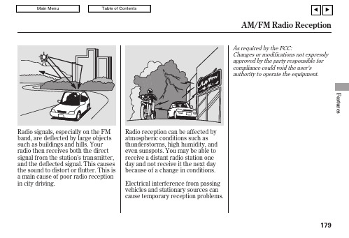
Radio signals,especially on the FM band,are deflected by large objects such as buildings and hills.Your radio then receives both the direct signal from the station’s transmitter,and the deflected signal.This causes the sound to distort or flutter.This is a main cause of poor radio reception in city driving.As required by the FCC:Changes or modifications not expressly approved by the party responsible for compliance could void the user’s authority to operate the equipment.AM/FM Radio ReceptionFeatures179The auxiliary input jack isunderneath the accessory power socket in the console compartment.The system will accept auxiliary input from standard audioaccessories using a 1/8inch stereo miniplug.When a compatible audio unit isconnected to the jack,press the AUX button to select it.Auxiliary Input Jack180The VOL button adjusts the volume up ()or down ().Press the top or bottom of the button,hold it until the desired volume is reached,then release it.If you are listening to the radio,use the CH button to change stations.Each time you press the top ()of the button,the system goes to the next preset station on the band you are listening to.Press the bottom ()to go back to the previous station.Three controls for the audio system are mounted in the steering wheel hub.These let you control basic functions without removing your hand from the wheel.The MODE button changes the mode.Pressing the buttonrepeatedly selects FM1,FM2,AM,XM Radio (U.S.models),a disc (if a disc is loaded),or a tape (if a tape is loaded).To activate the seek function,press and hold the top ()or bottom ()of the CH button until you hear a beep.The system searches up or down from the current frequency to find a station with a strong signal.If you are playing a disc,the system skips to the beginning of the next track (file in MP3or WMA format)each time you press the top ()of the CH button.Press the bottom ()to return to the beginning of the current track or file.Press it twice to return to the previous track or file.You will see the track/file number and the elapsed time.If the disc has text data or is compressed in MP3or WMA,you can also see any other information (track title,file name,folder name,etc.).CONTINUEDRemote Audio ControlsFeatures181If you make a mistake entering the code,do not start over;complete the five-digit sequence,then enter the correct code.You have 10tries to enter the correct code.If you are unsuccessful in 10attempts,you must then leave the system on for 1hour before trying again.Your vehicle’s audio system will disable itself if it is disconnected from electrical power for any reason.To make it work again,you must enter a specific five-digit code in the preset buttons.Because there are hundreds of number combinations possible from five digits,making the system work without knowing the exact code is nearly impossible.You should have received a card that lists your audio system code number and serial number.It is best to store this card in a safe place at home.In addition,you should write the audio system’s serial number in this owner’s manual.If you should happen to lose the card,you must obtain the code number from your dealer.To do this,you will need the system’s serial number.If your vehicle’s battery is discon-nected or goes dead,the audio system will disable itself.If thishappens,you will see ‘‘CODE’’in the frequency display the next time you turn on the e the preset buttons to enter the five-digit code.The code is on the radio code card included in your owner’s manual kit.When it is entered correctly,the radio will start playing.If the code card is lost,your dealer can access your code with yourradio’s serial number.To access the serial number,turn the radio on.It must display ‘‘CODE’’,then turn theradio off.Push the preset 1,preset 6,and power buttons at the same time,then quickly release.The serial number will appear.Radio Theft Protection182The security system automatically sets 15 seconds after you lock the doors, hood, and trunk. For the system to activate, you must lock the doors from the outside with the key, lock tab, door lock switch, or remote transmitter. The security system indicator next to the driver’s door lock starts blinking immediately to show you the system is setting itself.With the system set, you can still open the trunk with the remote transmitter without triggering the alarm. The alarm will sound if the trunk is opened with the trunk release button on the driver’s door, the trunk release handle behind the trunk pass-through cover, or the emergency trunk opener.Do not attempt to alter this system or add other devices to it.The security system helps to protect your vehicle and valuables from theft. The horn sounds and a combination of headlights, parking lights, side marker lights and taillights flash if someone attempts to break into your vehicle or remove the radio.This alarm continues for 2 minutes, then the system resets. To reset analarming system before the 2 minutes have elapsed, unlock the driver’s door with the key or use the remote transmitter.The security system will not set ifthe hood,trunk,or any door is notfully closed.If the system will not set, check the door and trunk openmonitor on the multi-information display(see page)to see if thedoors and trunk are fully closed.Since it is not part of the monitor display,manually check the hood.68Security SystemFeatures183Cruise control allows you to maintain a set speed above 25mph (40km/h)without keeping your foot on the accelerator pedal.It should be used for cruising on straight,openhighways.It is not recommended for city driving,winding roads,slippery roads,heavy rain,or bad weather.When climbing a steep hill,the automatic transmission may downshift to hold the set speed.Press and release the SET/DECEL button on the steering wheel.The CRUISE CONTROL indicator on the instrument panel comes on to show the system is now activated.Cruise control may not hold the set speed when you are going up and down hills.If your vehicle speed increases going down a hill,use the brakes to slow down.This will cancel the cruise control.To resume the set speed,press the RES/ACCEL button.The CRUISE CONTROL indicator on the instrument panel will come back on.3.Cruise Control184You can increase the set cruising speed in any of these ways:Press and hold the RES/ACCEL button.When you reach thedesired cruising speed,release the button.To increase the speed in very small amounts,tap the RES/ACCEL button.Each time you do this,your vehicle speeds up about 1mph (1.6km/h).Resting your foot on the brake or clutch pedal causes cruise control to cancel.Push on the accelerator pedal.Accelerate to the desired cruising speed,then press the SET/DECEL button.Even with cruise control on,you can still use the accelerator pedal to speed up for passing.Aftercompleting the pass,take your foot off the accelerator pedal.The vehicle will return to the set cruising speed.Changing the Set SpeedCruise ControlFeatures185Tap the brake or clutch pedal.Push the CANCEL button on the steering wheel.You can cancel cruise control in any of these ways:Push the CRUISE button on the steering wheel.Pressing the CRUISE button turns the system completely off and erases the previous cruising speed.When you push the CANCEL button,or tap the brake or clutch pedal,the system remembers the previously set cruising speed.To return to that speed,accelerate to above 25mph (40km/h)and then press andrelease the RES/ACCEL button.The CRUISE CONTROL indicator comes on,and the vehicle accelerates to the same cruising speed as before.Resuming the Set SpeedCancelling Cruise ControlCruise Control186If you are training HomeLink to operate a garage door or gate,you should unplug the motor for that device during training.Repeatedly pressing the remote control button could burn out the motor.HomeLink stores the code in a permanent memory.There should be no need to retrain HomeLink if your vehicle’s battery goes dead or is disconnected.If your garage door opener wasmanufactured before April 1982,you may not be able to programHomeLink to operate it.They do not have the safety feature that causesthe motor to stop and reverse if an obstacle is detected during closing,increasing the risk of injury.The HomeLink UniversalTransceiver built into your vehicle can be programmed to operate up to three remote controlled devices around your home,such as garage doors,lighting,or home security systems.Always refer to the openinginstructions and safety information that came with your garage door opener or other equipment youintend to operate with HomeLink.If you do not have this information,contact the manufacturer of the equipment.If you justreceived your vehicle and have not trained any of the buttons inHomeLink before,you should erase any previously learned codes before training the first button.If you are training the second or third buttons,go directly to step 1.For quick and accurate training,make sure the remote transmitter for the device (garage door,automatic gate,security system,etc.)has a fresh battery.To do this,press and hold the two outside buttons on the HomeLink transceiver for about 10seconds,until the red indicator flashes.Release the buttons,then proceed to step 1in the chart on the next page.Before you begin CONTINUEDGeneral InformationImportant Safety Precautions Training HomeLinkHomeLink Universal TransceiverFeatures187。
Warwick AMP 12SA 电子放大器说明书

OFFICIAL WARWICK AMP OWNER MANUALENGLISHTAKE12SAFETY HINTS- Read these instructions - Keep these instructions - Heed all warnings- Follow these instructionsCaution: To reduce the risk of electrical shock, do not remove the cover. Or expose this appliance to rain or moisture. No user serviceable parts inside;refer serving to qualified personnel.Apparatus shall not be exposed to dripping or splashing and no objects filled with liquids, such as vases shall be placed on the apparatus.This symbol, wherever it appears, alerts you to the presence of uninsulated dangerous voltage inside the enclosure--voltage that may be suffi-cient to constitute risk of shock.This symbol, wherever it appears, alerts you to important operating and maintenance instructi-ons in the accompanying literature. Read the manual.Use only with cart, stand, tripod, bracket or table specified by the manufacture, or cart/apparatuscombination to avoid injury from tip-over.Congratulations on the purchase of the new Warwick combo. Please read through these instructions before connecting and operating the device. If you keep to the guidelines set out in this manual, you will soon be able to appreciate the quality of this new Warwick amplifier. Please keep this instruction boo-klet handy in case you need to consult it again. Please send the PASSPORT to the address indicated the-rein.RECOMMENDATIONSThe following recommendations are designed to ensure that the device always functions reliably:•Never open the casing! To do so would expose you to the risk of an electric shock. Should repairs prove necessary, leave them to qualified service personnel.•Avoid dust and high moisture levels, direct sunlight and extremely high or low temperature.•Safeguard the device from excessive vibration. Always place the unit on a stable and horizontal surface.•See to adequate ventilation. The device should not be placed on soft surfaces (carpet, cushions, etc.). When mountingit in a rack, make sure that the rear and lateral cooling vents remain unobstructed.•Avoid leaving the unit near radiators or other objects producing heat.•Internal components should only be adjusted or cleaned by qualified service technicians. Ensure no object or liquid penetrates the device through its cooling vents.•When replacing a fuse make sure you fit in one of identical value!Have the device examined by a qualified service technician in the following cases:•the mains lead or mains switch have been damaged,•objects or liquids have penetrated the device,•it has been exposed to excessive moisture,•malfunctions or abnormal operating conditions have occurred,•the device has been dropped or the casing damaged.HINTS- This apparatus shall not be exposed dripping or splashing and that no objects filled with liquids, such as vases, shallbe placed on the apparatus.- This apparatus should be connected to a MAINS socket outlet with a protective earthing connection.-Mains plug or appliance connector shall be used as the disconnect device, so mains plug or appliance connector should always remain readily operable.- If the apparatus shows any malfunction, immediately disconnect the main power cord from the mains socket.- Do only operate effects pedals in-between the instrument and the amplifier, as these devices are not designed for the supplied load of an effects loop.- Remove the plug whenever changing a fuse.- Only ever replace a fuse with another of the same type. Never bridge defective fuses.- Make sure the top and bottom of the device are properly ventilated and that the vents are not blocked.- Do not subject the device to excessive vibration or hard jolts as these could damage the device.- Don't undertake repairs yourself.- Only allow the case to be opened by qualified personnel. (Remove the plug).- Repairs should only be undertaken by qualified personnel.SHOULD YOU FIND YOURSELF ONE DAY WONDERING: "WHY IS THERE NO SOUND COMING OUT?"please check:- all stub cables,- all connections of these cablesand proceed anew by following the guidelines of the chapter GETTING STARTED. Possibly the problem reveals to be an operational error.3PROTECTIVE CIRCUITSYour new Warwick amplifier is equipped with a series of circuits to prevent it from destruction in case of inadequate ope-rating conditions:Power-up delay:When the unit is switched on, the SPEAKER OUT sockets are activated with a slight delay toprotect the loudspeakers.Short-circuit:In the event of a short-circuit at the power amp outputs, this feature prevents the output stagetransistors from destruction by quickly reducing current.Direct current (DC):This circuit continuously monitors the power amp output for direct current and protects the loud speakers from overload should a transistor burn out.HF oscillation:By switching the power amp off, this safety feature prevents from damages that could be caused by frequencies in excess of 20 kHz (feedback, etc.).Excessivetemperatures:Should the temperature-regulated fan cooler prove to be insufficient in extreme conditions, this circuit protects the output stage transistors from destruction by switching the device off.Limiter:The combos CL and CCL are equipped with a limiter, that limits the poweramp outputs to200 watts (CL), 300 watts (CCL) in order to protect the loudspeakers.Note:You can recognise that one of these circuits has been activated as a result of a fault, when theMUTE LED glows continuously even though you have not selected the MUTE mode. In case ofa short-circuit please check the speaker cable. The amplifier must then be switched off and onagain, to get back into playing mode after having removed the short-circuit. In any other situationthe amplifier switches automatically back to playing mode as soon as it detects the fault hasdisappeared (e.g. the amplifier has overheated and cooled down again).GETTING STARTED1.Make sure that loudspeakers capable of sustaining the load of a bass signal are connected to the SPEAKER OUTsockets, resp. the speaker unit should be linked to the SPEAKER OUT at the combos.2.Check that the mains supply has been plugged in and that all external (effects) units possibly used are correctly con-nected and operational.3.Set the MASTER control to zero.4.Plug your bass guitar into the amplifier's INPUT with a shielded line-cable.5. Press the POWER switch to turn the device on.6. Switch MUTE off and the red LED will extinguish.7. Switch the LIMITER off (the 2-colored LED will extinguish, CL, CCL).8. Turn all volume controls of your bass guitar on to their maximum.9.Adjust the GAIN control until the (loudly) played bass signal flashes the clip LED.10.Set the MASTER control to the volume you wish to play at.11.Adjust the sound that you wish with the controls and switches described in the respective chapters FRONT PANELCONTROLS.12.If necessary readjust GAIN.13. Should you seek for a peak limited sound, activate the LIMITER(LED green) and fix its threshold (LED shifts to red)with GAIN.45FRONT PANEL CONTROLSINPUT socket to plug in a bass guitar.GAIN control + CLIP LED to adjust the input level.BASS control to boost/cut deep frequencies.MID LOW control to boost/cut low mids MID HIGH control to boost/cut high midsTREBLE control to boost/cut high frequencies.EFF. LOOP for the insertion of effects units. Connect SEND with the input and RETURN with the output of the effects device.LINE OUT socket allows to connect additional power amplifiers or active cabinets.MASTER control determines the mains level.MUTE switch + ON/MUTE LED cuts the signal from all outputs, except from the PHONES socket PHONES socket for connecting a headphone (min 200 Ω).REAR PANELMAINS IN AC Terminal with integrated fuse compartment for connecting the amplifier to the current network.POWERswitch for turning the amplifier on and off.SPEAKER OUT socket for connecting the loudspeaker.HORN OFFswitch to switch off the hf horn.TECHNICAL DATA67CIRCUIT DIAGRAMHeadquarters:WarwickGmbH&Co.MusicEquipmentKG•GewerbegebietWohlhausen•08258Markneukirchen/Germany•E-Mail:*************** Branch China:Warwick Music Equipment (Shanghai) Ltd., Co.•Shanghai Waigaoqiao Free Trade Zone • Shanghai 200131/P.R.China•E-Mail:*************** Branch UK:WarwickMusicEquipmentTrading(ManchesterUK)Ltd.•75BridgeStreet•ManchesterM32RH/GreatBritain•E-Mail:*******************.uk Branch Switzerland:WarwickMusicEquipmentTrading(Zurich)GmbH•Kriesbachstrasse30•8600Dübendorf/Switzerland•E-Mail:*************** Branch CZ:WarwickMusicEquipmentTrading(PrahaCZ)s.r.o.•Spálená23/93•11000Praha1/CzechRepublik•E-Mail:***************Visit us on the World Wide Web: http://www.warwick.de。
AM FM 收音机功能按键说明书
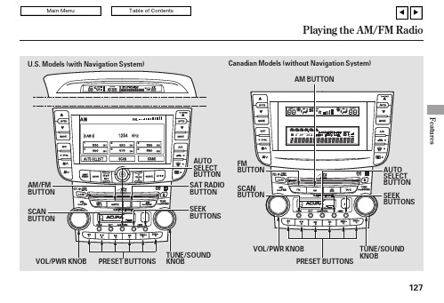
127The SEEK function searches up and down from the current frequency to find a station with a strong signal.To activate it,press the or SEEK button,then release it.The SCAN function samples all stations with strong signals on the selected band.Toactivate it,press the SCAN button,or touch the SCAN icon (models with navigation system),then release it.You will see SCAN in the display.The system will scan for a station with a strong signal.When it finds one,it will stop and play that station for about 5seconds.If you do nothing,the system will scan for the next strong station and play it for 5seconds.When it plays a station you want to listen to,press the SCAN button again.The band and frequency that the radio was last tuned to is displayed.To change bands,press the AM/FM button (AM or FM button onCanadian model).On the FM band,ST will be displayed if the station is broadcasting in stereo.Stereoreproduction on AM is not available.You can use any of five methods to find radio stations on the selected band:the preset buttons,and .Use the TUNE knob to tune the radio to a desired frequency.Turn the knob right to tune to a higher frequency,or left to tune to a lower frequency.The ignition switch must be in the ACCESSORY (I)or ON (II)position.Turn the system on by pushing the VOL/PWR knob or the AM/FM button (AM or FM button onCanadian model).Adjust the volume by turning the same knob.The audio system for your vehicle can also be operated using the voice control system.See Navigationsection in your Quick Start Guide for an overview of this system and the Navigation System manual for complete details.Only on models equipped with Navigation SystemSEEK SCAN To Select a StationTUNE,SEEK,SCAN,AUTO SELECT TUNE To Play the AM/FM RadioVoice Control System128Each of the six preset buttons or preset icons (on models with navigation system)can store one frequency on AM (LW,MW)and two frequencies on FM.Use the tune,seek,or scan function to tune the radio to a desired station.Repeat steps 1through 3to store a total of six stations on AM and twelve stations on FM.If you aretraveling far from home and can no longer receive your preset stations,you can use the auto select feature to find stations in the local area.Press the A.SEL button or the AUTO SELECT icon (models with navigation system).‘‘A.SEL’’(AUTO SEL)flashes in the display,and the system goes into scan mode for several seconds.It stores thefrequencies of six AM,and twelve FM stations in the preset buttons.press theA.SEL button (AUTO SELECT icon).This restores the presets you originally set.Select the desired band,AM or FM.FM1and FM2let you store two frequencies with each preset button (icon).Pick a preset button (icon),and hold it until you hear a beep.You will see a ‘‘0’’displayed or see no station number on the preset icons after pressing a preset button (icon)if auto select cannot find a strong station for every preset button.If you do not like the stations auto select has stored,you can store other frequencies on the preset buttons (icons).Use the TUNE,SEEK,or SCAN functions to find stations,then store them in the preset buttons (icons)as previously described.1.2.3.4.To turn off Auto Select,CONTINUEDPreset AUTO SELECT Features129On models without Navigation SystemEach mode is shown in the display as it changes.Turn the TUNE/SOUND knob to adjust the setting to your liking.When the level reaches the center,you will see ‘‘C’’in the display.The system will automatically return the display to the selected audio mode about 5seconds after you stop adjusting a mode.These two modes adjust the strength of the sound coming from the centerspeaker and the subwoofer speaker.If you turn the TUNE/SOUND knob all the way to the left,you will see ‘‘OFF’’in the display,and the center speaker and/or subwoofer speaker will be off.Bass,treble,balance,and fader are each adjustable.In addition,you can adjust the strength of the sound coming from the center and the subwoofer speakers.Press the TUNE/SOUND knob repeatedly to display the bass (BASS),treble (TREB),balance (BAL),fader (FADE),center (CNTR)and subwoofer (SUBW)setting.Adjusting the SoundCenter/Subwoofer 130On models with Navigation SystemTo adjust them,enter the sound grid by touching the SOUND icon on the display or pressing the TUNE/SOUND knob.To see the audio screen when you are finished adjusting the sound,touch the RETURN icon,or wait 5seconds.Bass,treble,left/right balance,and front/rear fader are each adjustable.In addition,you can adjust thestrength of the sound coming from the center and the subwoofer speakers.grid.When you touch an icon,the yellow bars on the grid turn orange and move toward the icon,changing the balance left or right.At this point,you can also use the TUNE/SOUND knob to adjust the balance.To equalize the balance,touch the left or right icon until each side has an orange bar at the center of the sound grid.To adjust the front/rear fader,touch the front or rear icon on the sound grid.When you touch an icon,the yellow bars on the grid turn orange and move toward the icon,changing the fader to the front or rear.At this point,you can also use the TUNE/SOUND knob to adjust the balance.To equalize the fader,touch the front or rear icon until each side has an orange bar at the center of the sound grid.treble and bass,touch or on each side of the treble or bass continue pressing or,or turn the TUNE/SOUND The adjustment bar shows you the current setting.To adjust the sound from the center speaker,touch or icon on each side of the subwoofer or center continue pressing or ,or turn theTreble/Bass Subwoofer/Center Features131。
1_AO711-S使用手册

1_AO711-S使用手册
AO711-S使用手册
在(-10%)以上。
量程上限表示位号的工程量高值,常见值为100
量程下限表示位号的工程量低值,常见值为0
4.2卡件故障分析处理
FAULT灯常亮,说明模块存在重故障,需要更换。
L-BUS灯常灭,说明通信故障或者指示灯电路损坏或者I/O总线上没有其他节点,请检查
通讯连接。
若L-BUS灯闪烁,说明地址有冲突,请检查总线上是否存在冲突的模块。
Supply灯不亮,说明外配24V电源没有连接好或者模块连接不可靠,请检查外配电源连接
和模块与基座的连接情况。
模块上电后,所有指示灯不亮,说明模块系统电源有问题。
检查系统电源连接,如果连接
可靠,则需要更换模块。
5资料版本说明
表5-1版本升级更改一览表
资料版本号输出时间更改说明
AO711-S使用手册(V1.0)适用模块版本:AO711-S-11.11.00 AO711-S使用手册(V1.1)适用模块版本:AO711-S-12.12.00 AO711-S使用手册(V1.2)适用模块版本:AO711-S-13.13.00 适用模块版本:AO711-S-13.13.00及以上
AO711-S使用手册(V1.3)更改基座选型
版本
5。
美高通电子产品操作手册说明书

About this ManualWe’ve added this manual to the Agilent website in an effort to help you support your product. This manual is the best copy we could find; it may be incomplete or contain dated information. If we find a more recent copy in the future, we will add it to the Agilent website.Support for Your ProductAgilent no longer sells this product. Our service centers may be ableto perform calibration and repair if necessary, but no other support fromAgilent is available. You will find any other available product information on the Agilent Test & Measurement website, .HP References in this ManualThis manual may contain references to HP or Hewlett-Packard. Please note that Hewlett-Packard's former test and measurement, semiconductor products and chemical analysis businesses are now part of Agilent Technologies. We have made no changes to this manual copy. In other documentation, to reduce potential confusion, the only change to product numbers and names has been in the company name prefix: where a product number/name was HP XXXX the current name/number is now Agilent XXXX. For example, model numberHP8648A is now model number Agilent 8648A.。
上海雅思乐使说明

上海雅思乐使说明
一、了解电吹管面板说明
打开包装就要事先查看用户手册,详细了解电吹管面板上的相关功能与日常使用注意事项。
比如:音色转换、调式转换这些功能如何操作,用户手册中都有说明。
二、吹奏前的准备
1、打开电吹管电源开关,显示屏幕亮起,即说明已经打开电源。
2、套上护带,护带的好处是吸收口中的唾液,防止唾液从外部随按键周围流入电吹管内部。
3、更改音色等操作,在显示屏幕的下方有音色、移调、MIDI、设置等功能选择键。
音色+-键:按任意键均可选择您喜欢的音色;
移调+-键:按任意键均可选择对应的音调;
MIDI键:初学者基本不用,这是针对专业的音乐制作或演奏而设置的功能,按键可以选择通道,与电脑连接完成录制与演奏。
设置键:按键可以进入吹力和舒适度的调整。
*吹力:001~005范围较合适,003为最佳模式。
*舒适度:H1为最佳模式。
三、开始演奏
1、呼吸、吹气,直到填满整个乐器。
使用萨克斯、笛子等指法都可以配合演奏键进行演奏。
2、将左拇指放在高、低音键之间,将右拇指放在拇指钩上。
3、使用八度音键,用左手拇指切换八度音,您可以升高或降低一个八度音。
四、电吹管维护
1、吹嘴因为吹奏有可能会弄脏,可以取下吹嘴用水清洗,并用软布擦干所有水滴。
2、将吹嘴插入电吹管的时候,要注意正面和背面是否正确定向。
3、吹奏完毕后,将电吹管斜靠在墙上或其他垂直的表面,以便电吹管内的唾液排出。
SAMS中控设备管理系统在智能生产操控中心的应用
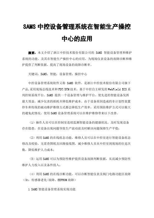
SAMS中控设备管理系统在智能生产操控中心的应用摘要:本文介绍了浙江中控技术股份有限公司的SAMS智能设备管理和维护系统的功能,及其在智能生产操控中心的应用,为现场仪表设备的故障诊断和维护提供了判断依据,提高了现场设备的故障诊断率。
关键词:SAMS;智能;设备管理;操控中心中控设备管理系统软件又称 SAMS 软件,是浙江中控技术股份有限公司旗下产品,采用现场总线技术和FDT/DTM技术,基于中控自主研发的WebField ECS系列控制系统平台。
SAMS 提供一个设备管理与维护平台,使先进的智能设备发挥最大效益,减少仪表的损耗并降低维护成本。
由于设备原因造成的非计划性装置停车和传统的被动维护维修方式都会降低生产效率,采用预防维护方式可以极大的避免此情况,使用SAMS设备管理系统可以在维护维修带来以下改善。
(1)操作人员可以在控制室连续监测智能设备的健康状况,及时发现设备存在隐患,在设备出现问题导致生产波动前及时解决问题保障生产平稳;(2)利用SAMS的在线组态功能,维修人员可以在中控室进行智能设备组态修改及校验,无需查图纸及回路接线图,减少维修人员从中控室到现场的往返次数,降低维护人力成本;(3)运用SAMS可以为预防性维护提供设备故障判断依据,从而减少预防性维护人力投入以及备件投入;(4)利用SAMS的在线诊断功能,可以诊断智能仪表及阀门电路功能区故障(如:传感器老化/故障、EEPROM故障)1 SAMS智能设备管理系统实现功能SAMS 基于微软(Microsoft)Windows 系列操作系统设计,简单易用。
目前SAMS 支持 HART 和 FF 智能设备管理和常规设备管理,用户可以方便地管理现场的 HART 设备和 FF 设备,实现以下功能:1.1在线组态SAMS软件可自动扫描与SAMS系统连接的智能仪表设备,使之在SAMS系统中上线,上线后的仪表可在SAMS软件中直接在线组态,修改仪表组态参数。
ECS-700硬件组态软件使用手册

ATTENTION: Identifies information that requires special consideration.
提示:标记对用户的建议或提示。 TIP:Identifies advice or hints for the user.
目录
1 概述..........................................................................................................................................................1-1 1.1 功能特点.......................................................................................................................................1-1 1.2 技术指标.......................................................................................................................................1-1
4 各类节点组态参数使用说明 ..................................................................................................................4-1 4.1 控制器...........................................................................................................................................4-1 4.2 I/O 连接模块..................................................................................................................................4-1 4.2.1 本地(虚拟)I/O 连接模块..............................................................................................4-1 4.2.2 I/O 连接模块.......................................................................................................................4-2 4.2.3 Profibus 主站通信模块 ......................................................................................................4-2 4.2.4 串行通信模块 ....................................................................................................................4-2 4.3 机架...............................................................................................................................................4-2 4.4 模拟信号输入模块 .......................................................................................................................4-3 4.5 热电阻信号输入模块 ...................................................................................................................4-3 4.6 热电偶信号输入模块 ...................................................................................................................4-3 4.7 脉冲信号输入模块 .......................................................................................................................4-4 4.8 电流信号输出模块 .......................................................................................................................4-4 4.9 模拟信号输出模块 .......................................................................................................................4-4 4.10 数字信号输入模块 .....................................................................................................................4-5 4.11 数字信号输入模块(SOE)......................................................................................................4-5 4.12 数字信号输出模块 .....................................................................................................................4-5 4.13 PAT 模块 ......................................................................................................................................4-6
迈博拉自动音频系统说明书

Contents Audio Systems2 Controls and Features7 Display16 Care and Cleaning17 Radio Frequency Information20 Index21Audio Systems Electronic Search Radio(ESR)Electronic Search Radio withCassette(ESC)ESC with Cassette &CD DJ (Compact Disc Changer)*Air conditioning systems optionalAudio SystemsE l e c t r o n i c S e a r c h R a d i o (E S R )E l e c t r o n i c S e a r c h R a d i o w i t h C a s s e t t e (E S C )E S C w i t h C D D J (C o m p a c t D i s c C h a n g e r )= Feature included on audio systemAudio System FeatureAudio SystemAudio Systemsl e c t r o n i c S e a r c h a d i o (E S R )l e c t r o n i c S e a r c h a d i o w i t h a s s e t t e (E S C )S C w i t h C D D J C o m p a c t D i s c h a n g e r )Audio System FeatureAudio SystemAudio SystemsUSING YOUR AUDIO SYSTEM Turning the power on/ adjusting the volumeTo turn the audio system on or off, press the power knob.To adjust the volume,turn the volume knob.If you turn off the ignition,the audio system will come back on at the preset medium level when the ignition is turned back on.•Turning the knob to the right will increase the volume.•Turning the knob to the left will decrease the volume.Using the AM/FM selectThe AM/FM select button works in radio,tape(if equipped),and CD (if equipped)modes.•In radio mode,the AM/FM select buttons allow choice betweenAM or FM frequency bands.Pressing the buttons switchesbetween AM,FM1,and FM2preset memory stations.•In cassette mode,pressing the AM/FM select buttons stopscassette play and begins radioplay.•In CD mode,pressing theAM/FM select buttons stops CDplay and begins radio play.AM FMControls and FeaturesUsing the tune adjustThe tune button works in radio or CD(if equipped)mode.•In radio mode,push to moveto the next frequency down the band(whether or not there is a listenable station located there).Push to move to the nextfrequency up the band(whether or not there is a listenablestation located there).Hold thebutton down to move quicklythrough the frequencies.•In CD mode,push to select the previous disc in the CDchanger.(Play will begin withthe first track of the disc unless the CD changer is in shufflemode.For more information onthe shuffle function,see Usingthe shuffle function in thisguide.)Hold the button down to continue reversing through thediscs.•Push to select the next disc in the CD changer.Hold thebutton down to fast forwardthrough the discs.Using the seek function•In radio mode,press seek or to find the next listenable station down the frequencyband.•Press seek or to find the next listenable station upthe frequency band.•In the tape mode,press seekor to listen to the previous tapeselection.Controls and Features•Press seek to listen to the next selection on the tape.•In CD mode,press seek trackto listen to the previous CD track.If a selection has beenplaying for more than threeseconds and the is pressed,the CD will replay the selection from the beginning.•Press seek track to listen to the next track on the CD.If you are playing the last track when is pressed,the disc will skip back to the first track on theCD.Using the scan function•In radio mode,press the scan button to hear a five-secondsampling of all listenablestations on the frequency band.To stop the scan mode on aparticular station,press thebutton again.•In tape mode,press the scan button to hear an eight-secondsampling of all tape selections.(The tape scans in a forwarddirection.At the end of thetape’s first side,the directionautomatically reverses to theopposite side of the tape.)Tostop at a particular tapeselection,press the scan button again.•In CD mode,press the scan button to hear an eight-secondsampling of all CD selections.(The CD scans in a forwarddirection,wrapping back to theControls and Featuresfirst track at the end of the CD.) To stop at a particular selection, press the scan button again. Using the radio station memorypresetThe radio is equipped with six station memory preset buttons. These buttons may be used to select up to six preset AM stations and twelve preset FM stations(six in FM1and six in FM2).To preset stations:e the AM/FM select buttons to choose a frequency band.2.Select a station.For more information on selecting a station, see Using the tune adjust in this guide.3.Press and hold a memory preset button until the sound resumes, indicating that the station is held in memory on the button that you selected.Using the bass and treble adjustThe bass and treble adjust buttons allow you to increase(+)or decrease(-)the bass and treble output.Controls and FeaturesUsing the speaker balance adjustSpeaker sound distribution may be adjusted between the right(+)and left(-)speakers by using the balance button.Speaker sound distribution may be adjusted between the front(+) and back(-)speakers by using the fade button.To test speaker functions,press and hold radio memory preset buttons three and six.The audio system will automatically run through each of the possible speaker outputs(front left,front right,rear left,rear right).The system display will show what speaker is being tested.Using your cassette player(if equipped)Push only slightly when inserting a cassette tape(with the open edge to the right).A cassette deck loading mechanism pulls the tape in the rest of the way.The ignition and radio do not need to be on to insert a tape.You can switch from CD(if equipped)to tape play by inserting a tape into the cassette deck.Controls and FeaturesUsing the tape/CD select(if equipped)•To begin tape play(with a tape loaded into the audio system),while in the radio or CD mode,press the tape button.Pressingthe button during rewind or fast forwarding stops the rewind orfast forward function.•To begin CD play(if CDs are loaded in the CD changer),press the CD button.The firsttrack of the disc will beginplaying.Using the rewind and fast forward functions(if equipped) To rewind a tape or CD,press the rewind button.To fast forward a tape or CD,press the fast forward button.•In tape mode,at the end of the first side of the tape thedirection automatically reversesand the opposite side of thetape plays.Controls and FeaturesUsing the tape direction select (if equipped)To play the alternate side of a tape,press the tape direction select button (preset #1).To stop and eject a cassette tape,press the eject button.If the radio power is on when you eject a tape,the radio begins playing.Dolby ாnoise reduction (if equipped)To activate and then deactivate the Dolby noisetape orCD mode,press the(preset #2).The noise reduction system is manufactured underlicense from Dolby Labs LicensingCorporation.Dolby andare trademarks of Dolby Laboratories Licensing Corporation.Using the compression adjust (if equipped)To bring soft and loud CD passages closer together for a moreconsistent listening level,press the compression adjust button (preset #5).Pressagain to turn off the feature.Controls and FeaturesUsing the shuffle function(if equipped)To listen to tracks on the current CD in random order,press the shuffle button(preset#6). Random order play continues until the button is pressed again. Setting the clockThe time is displayed:•until an audio function button is pressed.•approximately ten seconds after each audio system change.•when the audio system is off and the ignition is ON.To set the clock:1.Press the H and use the bass/ treble/speaker adjust button to move to the desired hour.2.Press the M and use the bass/ treble/speaker adjust button to move to the desired minute.If you choose to adjust only the hour or the minute(not both at the same time),adjust and the clock will automatically revert to the new time(complete with both adjusted and unadjusted digits displayed).Controls and FeaturesUsing the Ford compact disc player(if equipped)The CD changer is located in the trunk of your vehicle.To access the CD changer magazine,slide the magazine’s left door panel to the right.Press to eject the CD magazine fromThe CD magazine may be ejected or inserted without the vehicle key in the ignition and without the radio power on.Make sure that only one disc is inserted in each slot,and that the discs are inserted with the label surface upward.You may insert up to six discs.Insert the CD magazine into the changer.The magazine does not need to be full in order for the CD changer to operate.Radio power must be on in order to play the CDs in the CDchanger.Controls and FeaturesControls and FeaturesDisplayCare and Cleaning Troubleshooting problems withyour compact disc playerIf play does not begin once a discis inserted:•the radio is not on.•the unit is in the stop mode.•moisture is condensed on thelenses within the unit.Removethe disc and wait approximatelyone hour for moisture toevaporate.If the sound skips:•you may be traveling on a roughroad or playing badly scratcheddiscs.Skipping will not scratchthe discs or damage the player.If the CD player does not work:•the disc is already loaded intothe player.•the disc is inserted with thelabel surface downward.•the disc is dusty or defective.•the player’s internal temperatureis above75°C(167°F).Allowthe player to cool down beforeoperating.•a disc with format anddimensions not within industrystandards is inserted.Caring for your compact discsand player(if applicable)•Handle discs by their edges only.Never touch the playing surface.Care and Cleaning •Do not expose discs to direct sunlight or heat sources forextended periods of time.•Do not insert more than one disc into the CD player’s CDslot.Caring for your cassettes and cassette player(if applicable)•Only use cassettes that are90 minutes long or less.•Do not expose tapes to direct sunlight,high humidity,extreme heat,or extreme cold.Allowtapes that may have beenexposed to extremetemperatures to reach amoderate temperature beforeplaying.•Tighten very loose tapes by inserting a finger or pencil intothe hole and turning the hub.•Remove loose labels before inserting tapes.•Do not leave tapes in thecassette player for an extended period when not being played.Radio Frequency Information RADIO FREQUENCYINFORMATIONThe Federal CommunicationsCommission(FCC)and theCanadian Radio andTelecommunications Commission(CRTC)establish the frequenciesAM and FM stations may use fortheir broadcasts.Allowablefrequencies are:AM530,540—1600,1610kHz in10kHz stepsFM87.9,88.1—107.7,107.9Mhzin.02Mhz stepsNot all frequencies are used in agiven area.Radio reception factorsThree factors primarily affect radioreception:•Distance/strength.The fartheran FM signal travels,the weakerit is.The listenable range of theaverage FM station isapproximately40km(24miles).This range can be affected bysignal modulation.Signalmodulation is a process radiostations use to increase theirstrength and/or volume relativeto other stations.•Terrain.Hills,mountains,andtall buildings between yourvehicle’s antenna and the radiostation signal can cause FMsignal reception problems.Staticcan be caused on AM stationsby power lines,electric fences,traffic lights,and thunderstorms.Radio Frequency Information Moving away from theinterfering structure(out of its“shadow”)returns yourreception to normal.•Station overload.Weakstations are sometimes capturedby stronger stations when youpass a broadcast tower.Astronger station may temporarilyovertake a weaker station andplay while the weak station’sfrequency is displayed.The audio system automaticallyswitches to single channelreception if it will improve thereception of a station normallyreceived in stereo.AM/FM select (6)Audio power (6)Bass adjust (9)Cassette player operation..............................10,18 CD select. (11)Cleaning your vehicleCD player and discs (17)Clocksetting the clock (13)Compact disc changer care (17)operation (14)troubleshooting (17)Compression adjust (12)Display (16)Dolbynoise reduction..............12Fast forward function.. (11)Memory preset buttons (9)Power button (6)Radio frequency information (19)reception (19)Rewind function (11)Scan function (8)Seek function (7)Shuffle mode (13)Speaker balance adjust (10)Stations selecting (9)Tape direction select (12)Tape select (11)Treble adjust (9)Tune adjust (7)Index21。
主板上常见的场管型号代换及检测
主板上常见的场管型号代换及检测
主板上常见的场管型号代换及检测
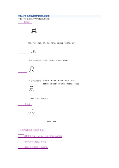
N沟道:
702、712、G16、SG、SS、7EW、12KSH、72KGG、KF
中等大小的场管:3055、09N05、40N03、45N03
外型较大的场管:L3103S、K3296、K3289、6030、7030
55N03、76139D、76129S、10N03、15M03
F827、F841、BPS100
P沟道:
352A、356
场管的代换原则(只适合主板)
场管代换只需大小相同,分清N沟道P沟道即可
功率大的可以代换功率小的
技嘉主板的场管最好原值代换
用万用表测量场效应管极性及好坏判断
1、测量
极性及管型判断
红笔接S、黑笔接D值为(300-800)为N沟道
红笔接D、黑笔接S值为(300-800)为p沟道
如果先没G、D再没S、D会长响,表笔放在G和最短脚相连放电,如果再长响为击穿
贴片场管与三极管难以区分,先按三极管没,如果不是按场管测
场管测量时,最好取下来测,在主板上测量会不准
2、好坏判断
测D、S两脚值为(300-800)为正常,如果显示“0”且长响,场管击穿;如果显示“1”,场管为开路
软击穿(测量是好的,换到主板上是坏的),场管输出不受G极控制。
- 1、下载文档前请自行甄别文档内容的完整性,平台不提供额外的编辑、内容补充、找答案等附加服务。
- 2、"仅部分预览"的文档,不可在线预览部分如存在完整性等问题,可反馈申请退款(可完整预览的文档不适用该条件!)。
- 3、如文档侵犯您的权益,请联系客服反馈,我们会尽快为您处理(人工客服工作时间:9:00-18:30)。
FF接口模块AM712-S
1基本说明
FF接口模块AM712-S为符合FF(基金会现场总线)标准的现场仪表与ECS-700系统提供通讯接口。
AM712-S在网络中处于I/O模块层,通过本地I/O总线将FF仪表接入ECS-700系统。
AM712-S支持两条相互隔离的FF-H1(FF低速现场总线)网段,每个网段可下挂16台FF设备。
AM712-S支持标准的FF现场总线功能块。
FF组态软件VFFFBuilder可通过AM712-S对现场设备功能块参数进行管理。
AM712-S在ECS-700系统架构中的位置如图 1-1所示。
图 1-1 AM712-S在ECS-700系统架构中的位置
1.1功能特点
AM712-S模块具有以下功能特点:
¾支持模块冗余。
¾支持模块热插拔。
¾高互可操作性,支持基金会注册的标准FF仪表的接入与使用。
¾支持两条标准的FF-H1网段。
¾每条网段可挂接多至16台标准FF设备。
¾具有LAS功能,默认作为网段的主LAS。
¾支持24个IO位号点(AI+AO+DI+DO≤24)。
2性能指标
表 2-1性能指标一览表
条目产品规格
ECS-700系统可接入的AM712-S模
块数量一个控制站最多可带64个非冗余AM712-S或64对冗
余AM712-S
FF网段接入能力2个H1网段
两网段支持的IO位号总数 (AI+AO+DI+DO≤24)
H1单网段设备最大挂接数量最大16台FF仪表
支持的仪表种类经过FF基金会测试认证的FF仪表
控制功能控制功能统一由控制器执行
组态软件 VFFFBuider,集成于VF
FF组态下载方式支持全网段下载
本地I/O通讯速率1Mbps
H1通讯速率31.25Kbps
机架供电额定电压(24±5%)V
H1总线电压范围(18~32)V
AM712-S功耗 1.5W
启动冲击电流3A
静电放电抗扰度:3B
电快速瞬变脉冲群抗扰度:3B
EMC指标
浪涌(冲击)抗扰度:2A
IP 防护等级IP30
工作温度 (0~50)℃
工作相对湿度 (5~95)%RH,无凝露
工作大气压 (62~106) kPa
供电/防爆总线供电/支持现场设备的本安防爆
掉电保护支持
冗余能力支持
热插拔支持
防混插支持
3使用说明
3.1结构简图
FF接口模块单元由模块AM712-S和基座MB734-S构成,FF接口模块单元结构示意图如下图所示。
图3-1 FF接口模块单元结构示意图
3.2接线说明
如图3-1所示,基座上配有两组接线端口Port 1和Port 2,Port 1(L)与Port 1(R)为一对冗余端口,用于连接H1第一网段的现场总线;Port 2(L)与Port 2(R)为另一对冗余端口,用于连接H1第二网段的现场总线。
冗余端口支持H1电源模块到AM712-S之间的总线1:1冗余,每个端口包括3位接线端子。
其中中间的接线端子用于连接现场总线线缆的屏蔽线;两边的接线端子用于连接H1现场总线信号。
端子和总线的具体连接方法如图 3-2所示。
图 3-2 AM712-S接线端口示意图
若H1电源模块的主机侧端口冗余,且需要H1电源模块到AM712-S之间的总线冗余,则接线说明如图 3-3及表 3-1所示。
图 3-3 H1电源模块到AM712-S之间的总线冗余示意图
表 3-1 AM712-S冗余接线说明
冗余时接线说明
端口
左侧端子接线说明右侧端子接线说明
+ S - + S - Port1 1 2 3 1 2 3 Port2 4 5 6 4 5 6
若H1电源模块的主机侧端口不冗余,则接线说明如图 3-4及表 3-2所示。
图 3-4 H1电源模块到AM712-S之间无总线冗余示意图
表 3-2 AM712-S非冗余接线说明
非冗余时接线说明
端口
左侧端子接线说明右侧端子接线说明
+ S - + S - Port1 1 2 3 不接不接不接
Port2 4 5 6 不接不接不接
表 3-1和表 3-2所提到标识说明如表 3-3所示。
表 3-3 AM712-S标识说明
标识名称说明
Port1 端口一接H1第一网段的现场总线
Port2 端口二接H1第二网段的现场总线
+ 信号正接H1现场总线的正极。
S 屏蔽地接H1现场总线的屏蔽层。
- 信号负接H1现场总线的负极。
3.3LED指示灯说明
3.3.1AM712-S模块指示灯说明
表 3-4 AM712-S模块指示灯一览表
灯常态其它状态非常态含义
亮重故障
Fault 灭
闪——
1s闪组态错误
Status 亮
200ms闪组态更新
亮工作模块
Duplex
灭备用模块
灭两路L-BUS总线故障
L-Bus 亮
1s闪地址冲突
灭两路H1通讯均出问题
H1 亮
1s闪某路H1通讯出现故障
3.3.2MB734-S基座指示灯说明
表 3-5 AM712-S基座指示灯一览表
灯常态其它状态非常态含义
P_LED 亮灭 H1电源没有连接上
R_LED 闪灭没有接收到H1信号
T_LED 闪灭没有发送H1信号
4工程应用
4.1应用注意事项
¾现场总线施工方法请参照现场总线基金会发布的《FF工程应用指南》。
¾AM712-S有专用基座MB734-S,不能和其他I/O模块的基座混用,其他I/O模块也不能使用MB734-S。
4.2模块故障分析处理
¾若所有的灯都不亮,说明系统电源没有接好,检查供电是否正常。
¾若Fault灯亮,说明该模块重故障。
需更换模块,并重新下载组态。
¾若Status灯闪,说明该模块组态不完整或不正确。
需先下载H1组态,再下载DCS组态。
¾L-Bus灯常灭,说明该模块两路CAN通讯故障。
检查两路本地I/O总线是否正常。
¾L-Bus灯闪,说明该模块的槽位号与网络上其他模块有冲突,检查机架跳线是否正确,模块安装是否规范。
¾H1灯常灭,说明该模块两路H1通讯故障。
检查两路H1现场总线及现场设备连接是否正常。
¾H1 灯闪,说明该模块有一路H1通讯故障。
检查两路H1现场总线及现场设备连接是否正常。
¾P_LED灭,说明电源没有连接上。
检查H1电源供电是否正常,接线是否良好。
¾R_LED灭,说明该模块没有接收到H1信号。
检查H1电源供电及仪表接线是否正常。
¾T_LED灭,说明该模块没有发送出H1信号。
检查H1电源供电是否正常,接线是否良好,模块安装是否规范。
若这些都没有问题,请更换AM712-S模块,重新下载组态。
5资料版本说明
表 5-1版本升级更改一览表
资料版本号更改说明
AM712-S使用手册(V1.0)适用模块版本:AM712-S-11.10.00。