EPI流量计说明书
Pel 102 103 电子计量仪说明书
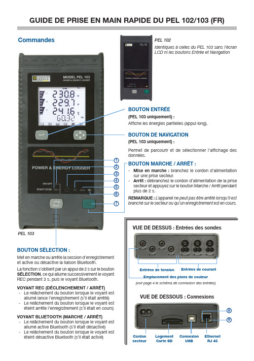
BOUTON MARCHE / ARRÊT :-Mise en marche : branchez le cordon d’alimentation sur une prise secteur.-Arrêt : débranchez le cordon d’alimentation de la prise secteur et appuyez sur le bouton Marche / Arrêt pendant plus de 2 s. REMARQUE : L ’appareil ne peut pas être arrêté lorsqu’il est branché sur le secteur ou qu’un enregistrement est en cours.Entrées de tensionEmplacement des pions de couleur Cordon secteur Logement Carte SD ConnexionUSB Ethernet RJ 45Entrées de courantPEL 103(PEL 103 uniquement) :Permet de parcourir et de sélectionner l’affichage des données.BOUTON SÉLECTION :Met en marche ou arrête la session d’enregistrement et active ou désactive la liaison Bluetooth.La fonction s’obtient par un appui de 2 s sur le bouton SÉLECTION , ce qui allume successivement le voyant REC pendant 3 s, puis le voyant Bluetooth.VOYANT REC (DÉCLENCHEMENT / ARRÊT)-Le relâchement du bouton lorsque le voyant est allumé lance l’enregistrement (s’il était arrêté) -Le relâchement du bouton lorsque le voyant est éteint arrête l’enregistrement (s’il était en cours)VOYANT BLUETOOTH (MARCHE / ARRÊT)-Le relâchement du bouton lorsque le voyant est allumé active Bluetooth (s’il était désactivé)-Le relâchement du bouton lorsque le voyant est éteint désactive Bluetooth (s’il était activé)754321698Installation de DataView ®NE CONNECTEZ PAS L’INSTRUMENT AU PC AVANT D’AVOIR INSTALLÉ LES LOGICIELS ET LES PILOTES.1.Branchez le CD dans son lecteur.Si l’exécution automatique est activée, le programme démarre automatiquement dans votre navigateur. Si l’exé-cution automatique n’est pas activée, sélectionnez Start.html dans D:\SETUP (si votre lecteur de CD-ROM est le lecteur D ; sinon, remplacez D par la lettre de lecteur appropriée).2. Sélectionnez votre langue et cliquez sur ENTRÉE . Autorisez votre navigateur à ouvrir le fichier.3. Sélectionnez la colonne Logiciel.4.Sélectionnez DataView ou PEL Transfer si vous ne souhaitez installer que PEL Transfer.5. Téléchargez le fichier et décompressez-le.6. Sélectionnez Setup.exe et suivez les instructions.REMARQUE : Pour des instructions d’installation complètes, reportez-vous au manuel fourni sur le CD-ROM.Carte SDIntroduisez la carte SD fournie dans le PEL.Le PEL prend en charge les cartes SD (jusqu’à 2 Go) et SDHC (entre 4 et 32 Go).• Une carte de 2 Go peut contenir 4 semaines d’enregistrements si vous n’enregistrez pas les harmoniques.• Lorsque la carte SD est dans l’appareil, il est possible de la formater, dans certaines conditions, lorsquevous êtes connecté à Dataview ®.• Un formatage est possible sans restriction si la carte est inséréedans un PC en utilisant le lecteur de carte fourni.• L’extraction à chaud est possible si aucun enregistrementn’est en cours.Ouverture de PEL Transfer• Branchez le cordon d’alimentation sur une prise secteur.L’appareil se met en marche.• Raccordez le PEL au PC avec le câble USB fourni. Attendez queles pilotes aient fini de s’installer avant de continuer.• Double-cliquez sur l’icône du PEL sur le bureau pour ouvrirPEL Transfer.• Sélectionnez l’icône Ajouter un appareil dans la barred’outil ou dans le menu principal Appareil .• Suivez les instructions de l’assistant Ajouter un appareil . SiPEL Transfer ne détecte pas l’appareil dans la liste déroulante, cliquez sur le bouton Actualiser ou débranchez, puis rebranchez le câble USB.• Lorsque la connexion avec l’appareil est établie, le nom de cedernier doit s’afficher sur le côté gauche de la fenêtre dans la branche Réseau PEL de l’arborescence.Configuration de l’appareilPour configurer votre PEL, sélectionnez l’appareil dans le répertoire Réseau PEL.Ouvrez la boîte de dialogue Configurer l’appareil en cliquant sur l’icône Configurer dans la barre d’outils,dans le menuAppareil ou dans la zone État .Cette boîte de dialogue comporte cinq onglets :• Général : Comporte des champs permettant d’attribuer des libellés à l’appareil, des options de commanded’arrêt automatique, de commande de l’afficheur LCD, de boutons de fonctionnement, de réglage de l’horloge et de formatage de la carte SD.• Communication : Options relatives à la liaison Bluetooth et au réseau LAN.• Mesure : Sélection du système de distribution, rapport des tensions, sélection de la fréquence et réglagedes capteurs de courant.• Enregistrement :Options de sélection des paramètres d’enregistrement.• Compteurs : Réinitialisation des compteurs et options de réinitialisation des compteurs d’énergie partielle.Cliquez sur le boutonpour transférer sur l’appareil la nouvelle configuration.Exemple de répertoire Réseau PELInstallation des sondes et des capteurs de courantDouze jeux de bagues et de pions de couleurs sont fournis avec l’appareil. Utilisez-les pour identifier les sondes et les bornes d’entrée.• Détachez les pions et placez-les dans les trous sous les bornes (les grands pour les bornes de courant, les petits pour les bornes de tension).• Clipsez une bague de la même couleur à l’extrémité de la sonde qui sera branchée sur la borne.• Mesure du courant : connecteurs 4 points I1, I2, I3• Mesure de la tension : bornes V1, V2, V3 et NLes sondes de mesure doivent être connectées au circuit à surveiller selon le schéma de branchement sélectionné. N’oubliez pas de définir le rapport de transformation lorsque nécessaire.MontageLe PEL comporte des aimants incorporés qui permettent de le fixer sur une surface magnétique.Lancement d’un enregistrement (Marche / Arrêt)Pour lancer un enregistrement, procédez de l’une des manières suivantes :• Dans PEL Transfer : Sélectionnez l’option appropriée dans l’onglet Enregistrement de la boîte de dialogue Configuration. L’appareil peut être configuré pour déclencher un enregistrement soit à une date et une heure future, soit immédiatement après écriture de la configuration sur l’appareil.• Sur l’appareil : Appuyez sur le bouton SÉLECTION et maintenez-le appuyé jusqu’à ce que le voyant vert s’allume, puis relâchez-le. L’appareil démarre l’enregistrement selon les réglages de configuration précédents. Pour arrêter un enregistrement, procédez de l’une des manières suivantes :• Dans PEL Transfer : Dans le menu, sélectionnez Appareil > Arrêter l’enregistrement .• Sur l’appareil : Appuyez sur le bouton SÉLECTION et maintenez-le enfoncé jusqu’à ce que le voyant vert s’allume, puis relâchez-le.Affichage de l’enregistrementLes données enregistrées peuvent être transférées de deux manières sur le PC pour y être affichées et pour générer des rapports :• La carte SD peut être retirée de l’appareil et branchée sur le PC via le lecteur de carte SD fourni. Lancez PEL Transfer, sélectionnez la commande Ouvrir dans le menu Fichier, pointez le fichier ICP portant le numéro de session souhaité sur la carte SD et sélectionnez Ouvrir.• Connexion directe entre le PC et le PEL (USB, réseau ou Bluetooth). Lancez PEL Transfer, ouvrez une connexion vers l’appareil, sélectionnez-le (veillez à ce qu’il soit connecté) dans l’arborescence, puis sélectionnez Sessions enregistrées. Double-cliquez sur la session d’enregistrement souhaitée.Le téléchargement terminé, sélectionnez le test téléchargé et cliquez sur le bouton Ouvrir dans la boîte de dialogue Téléchargement. Dans les deux cas, la session s’ajoute à Mes sessions ouvertes dans l’arborescence. Les données peuvent alors être affichées.09 - 2012Code 693779A01 - Ed. 1。
便携式多普勒超声波流量计使用说明

便携式多普勒超声波流量计使用说明示例文章篇一:哎呀,亲爱的朋友们,你们知道吗?今天我要给大家讲讲这个超级厉害的便携式多普勒超声波流量计!这东西看起来小小的,可作用大着呢!就像我们小小的身体里藏着大大的能量一样。
它的外观呀,不大不小刚刚好,能被我们轻松地拿在手里。
上面有一些按钮和屏幕,就像我们玩的游戏机,不过可别小瞧这些按钮和屏幕,它们可有大用处!当我们要用它的时候,第一步,得先把它打开,这就好比我们早上起床睁开眼睛,准备迎接新的一天。
然后呢,我们要根据测量的东西,设置好相应的参数。
这可有点像我们做数学题,得选对公式才能得出正确答案。
比如说,如果我们要测量水流,那就要把和水流相关的数值设定好。
你说这是不是很神奇?再然后,我们把这个流量计的探头放到要测量的地方。
这探头就像是我们的小侦察兵,去获取最准确的信息。
“哎呀,这能测准吗?”你可能会这么问。
放心啦!它可准啦,就像我们的眼睛看东西一样清楚准确。
在测量的过程中,我们要注意保持探头的稳定,不能乱动。
不然它就像被我们捣乱的小伙伴,会生气,给出不准确的结果哟。
测量结束后,数据就会显示在屏幕上啦。
我们可以清楚地看到各种信息,比如流速啦、流量啦等等。
这多方便呀!你看,这个便携式多普勒超声波流量计是不是很棒?它就像我们的好帮手,能帮我们快速又准确地获取各种测量数据。
我觉得呀,有了它,很多工作都会变得轻松又高效,难道不是吗?所以呀,大家都要好好了解它,学会使用它,让它发挥出最大的作用!示例文章篇二:哇塞!今天我要跟大家讲讲这个超厉害的便携式多普勒超声波流量计!你们知道吗?这玩意儿就像是一个神奇的小助手,能帮我们解决好多问题呢!想象一下,一条河流奔腾不息,我们想知道水在里面流得有多快,流量有多大。
这时候,便携式多普勒超声波流量计就派上用场啦!它的样子不大不小,拿在手里刚刚好。
上面有一些按钮和屏幕,可别小看这些哦!当我们要使用它的时候,第一步,先把它打开,就像打开一个神秘的宝箱一样。
EPI流量计安装指南

一;插入式流量计和管道的连接。
1如果过程气体压力不大,可采用有内螺纹焊接管座,流量计安装时,一般插入距离(上)下管壁1/4D(管道内径)出计算好长度后,准备好管座,垂直焊接在管道上即可。
安装时要保证气流方向与流量计探杆相互垂直。
如果压力超过1MPa,一般采用法兰连接。
要保证流量计探杆末端什么;UP;未迎接气流方向,要和现场实际气流方向垂直。
同时要保证上游管道直管段长度,前10D后5D .有弯头未15D ,。
{8280MP为1 1/4NPT螺纹。
8840MP为3/4NPT螺纹。
二电气连接该流量计为四线制,24VDC.。
三;上电后如果气体参数没有定货前发生变化,无需修改参数。
NCMH—表示标准立方/小时,瞬时流量。
NCM—表示累计流量,标准立方米。
四;参数调整方法,仪表键盘设置操作。
4.1输出量程调整方法(140菜单)在上电状态下,首先;解锁,。
按MODE键2次入200菜单,按MAX,键到219项UNLOCK,按SHIFT键,输入9001(MAX,MIN 键改变数值,MODE键用来移位)。
然后按SHIFT键。
当LCD显示右上方出现“》”号,表面解锁成功。
然后,按MAX 键2次进入--------------------------按SHIFT 键选择100 Meter然后按MAX 键进入然后按SHIFT 键进入用MAX. MIN 键修改数值,用MODE 键移动光标。
修改完成后按SHIFT 键储存回到后,按MAX 键4次进入然后按SHIFT 键返回运行模式。
4.2 显示值调大的操作。
首先 解锁按MODE 键2次入200菜单,按MAX,键到219项 UNLOCK,按SHIFT 键,输入9001(MAX,MIN 键改变数值,MODE 键用来移位)。
然后按SHIFT 键。
当LCD 显示右上方出现“ 》”号,表面解锁成功。
按MAX 键5次,进入800菜单,按SHIFT 键选择800-FACTORY,然后按MAX 键进入811-C FACTOR,原来数值是1.0,输入0.85显示值较原来数值减小15﹪。
流量计仪表操作说明

目录仪表的键盘和前面板-------------------------------------2 仪表功能----------------------------------------------------4 仪表程序----------------------------------------------------4 仪表键盘和中控方式的转换----------------------------6 仪表的启动和停止----------------------------------------7 仪表重量和容积方式的转换----------------------------8 给定量的输入----------------------------------------------8 显示事件信息----------------------------------------------8 服务数据----------------------------------------------------9 标定功能----------------------------------------------------9 调零-----------------------------------------------------14 计数器1或2的复位-------------------------------------13 安装与调整-------------------------------------------------13 维护与保养-------------------------------------------------14 事件信息----------------------------------------------------16(一)仪表的键盘1各按键的作用如下:启动键和停止键。
EPI流量计说明书.
A节简介和安装介绍你的主触摸™流量计包括流量传感元件,温度传感元件,桥式放大器/信号输出板,微处理器电路板,变送器外壳和探头支持或流量部分。
根据您的要求,可能是这些个别集成到一个流量变送器组件,或者你可能有一个额外的流量变送器信号处理器组装(远程电子)。
在这两种配置中,微处理器转换非线性输入信号从线性0-5 VDC4-20 mA输出流量变送器信号。
各种其他可选的通信协议,包括RS232/RS485,火线™红外模块,数据记录与EPICommunicator ™2.0和Modbus或HART兼容模块。
仪器的开箱你的主触摸™热式质量流量计是一种精密的电子流量仪表。
虽然这些流量计是坚固耐用的,他们应在交货时检查,以确保没有损害发生于运送途中。
如果经检查发现,损害已经发生,立即通知承运人,并把货物损坏索赔。
运输容器或箱子应谨慎处理,小心打开,以避免可能造成的损害的内容。
后容器被打开的内容,应仔细清除,并检查各个部分对照装箱单。
请注意,装箱清单会显示所有选项为您的仪器订购。
许多,如果不是全部,这些选项将被纳入流仪表本身并不会是单独的组件。
最后验证检查设备校准范围如流量计的文档上显示匹配你的采购订单规格。
如果您发现不符或有任何疑问,你是怎样领受,立即联系EPI。
电源要求电源要求主触摸™流量计“DC24”选项,为用户提供18至24伏特DC@250毫安。
主触摸™流量计“AC115”选项电源要求115 V AC,50/60赫兹标准,或220 V AC,50/60赫兹“AC230”选项。
如果管道是用来括电源输入线,它应该适合于该应用,导电性,和内连接外壳接地。
我们的建议电线尺寸为18佐治亚州的所有AC搁浅接线。
如果流量计包括一个远程电子组装,然后流量变送器电源提供连接到远程组件(见G部分对应的接线说明你的配置)。
十英尺的两导线连接电缆提供与远程组件。
如果更多的电缆是必需的,应替换为一个两线,双绞屏蔽电缆10'的长度。
EPI热质量流量计

EPI 流量传感器是温度补偿型的,无需压力补偿。这使得传感器可以提供真实的质量流量信号。因为 无需校正,信号可以直接与过程或数据采集系统连接。
工作压力 BarG 8.6 3.8
性能指标: 线性信号输出:0—5VDC & 4—20mA 满刻度重复性:0.2%满刻度 精度(参考温度 21℃):±[1%读数+(0.5%满刻度+0.02%/℃) 传感器响应时间:1 秒 信号响应时间:1 秒 量程比:最小 100:1,最大 300:1 气体温度范围:-40--200℃ 电子部件温度范围:0--50℃(如要较大的温度范围,请和我们联系) 最大额定压力值:500PSIG 变送器需要功率:0.8—6W 电源(15W):115VAC 50/60HZ (220VAC、24VDC 可选) 变送器外壳:额定等级 Class 1, Division 1,B,C,D 组和 NEMA4 信号处理外壳:玻纤 NEMA4X,尺寸 8x10x4″法兰,6x10-3/4″和 1/4″螺栓连接 润湿部件:316SS(可选哈氏合金或蒙乃尔合金) 标准温度和压力(STP):21.1℃ / 760mmHg NIST 标定:空气和其他气体
4
卫生 / 实验 石油天然气工业 燃烧气体测量 / 气体质量研究 / 废气回收 / 气体混合 / 泄露测试 / 计量 / 修补 过程控制 气体干燥 / 入口气体 / 通风系统 / 助燃气体 / 压缩机管道 / 燃烧控制 / 封闭容器 原料工业 造纸和纸浆 / 半导体制造 / 铁矿 / 采矿 / 化工处理 / 塑料合成 / 钢铁精炼 / 钢铁退火 纺织工业 天然气消耗 / 天然气计量 / 压缩空气监视 / 燃烧控制 公用工程 电厂、天然气厂、水厂、污水处理厂监控以下部位:烟气 / 通风系统 / 气体流量 / 助燃空气 /
EPI-1711VNA 说明书

EPI-1711VNALGA775 800MHz外频P4级全长卡带VGA/LAN/Audio版本:A1声明除列明随产品配置的配件外,本手册包含的内容并不代表本公司的承诺,本公司保留对此手册更改的权利,且不另行通知。
对于任何因安装、使用不当而导致的直接、间接、有意或无意的损坏及隐患概不负责。
订购产品前,请向经销商详细了解产品性能是否符合您的需求。
EVOC是研祥智能科技股份有限公司的注册商标。
本手册所涉及到的其他商标,其所有权为相应的产品厂家所拥有。
本手册内容受版权保护,版权所有。
未经许可,不得以机械的、电子的或其它任何方式进行复制。
安全使用小常识1.产品使用前,务必仔细阅读产品说明书;2.对未准备安装的板卡,应将其保存在防静电保护袋中;3.在从防静电保护袋中拿出板卡前,应将手先置于接地金属物体上一会儿(比如10秒钟),以释放身体及手中的静电;4.在拿板卡时,需佩戴静电保护手套,并且应该养成只触及其边缘部分的习惯;5.为避免人体被电击或产品被损坏,在每次对主板、板卡进行拔插或重新配置时,须先关闭交流电源或将交流电源线从电源插座中拔掉;6.在需对板卡或整机进行搬动前,务必先将交流电源线从电源插座中拔掉;7.对整机产品,需增加/减少板卡时,务必先拔掉交流电源;8.当您需连接或拔除任何设备前,须确定所有的电源线事先已被拔掉;9.为避免频繁开关机对产品造成不必要的损伤,关机后,应至少等待30秒后再开机。
目录第一章产品介绍 (1)简介 (1)订购信息 (1)环境与机械尺寸 (2)微处理器 (2)芯片组 (2)系统存储器 (2)网络功能 (2)USB功能 (2)PICMG总线 (3)显示功能 (3)音频功能 (3)外部I/O接口功能 (3)IrDA 接口 (3)IDE功能 (3)SATA功能 (3)看门狗定时器 (4)电源管理规范 (4)第二章安装说明 (5)产品外形 (5)接口位置示意图 (6)跳线功能设置 (7)系统内存的安装 (8)SATA接口 (8)IDE接口 (9)并口 (10)串口 (10)网络接口 (11)键盘与鼠标接口 (11)USB接口 (12)显示接口 (12)音频接口 (13)IrDA/红外接口 (14)风扇接口 (14)电源接口 (14)状态指示灯接口 (16)EPI接口 (17)第三章BIOS功能简介 (19)附录 (20)Watchdog编程指引 (20)I/O口地址映射表 (23)IRQ中断分配表 (24)第一章产品介绍第一章产品介绍简介EPI-1711VNA是采用Intel 865GV+ICH5芯片组设计的,支持LGA 775 架构的533/800MHz外频P4级别处理器的全长卡。
流量计说明书
流量计说明书流量计说明书篇一:流量计使用方法及问题解析流量计外观及使用方法如下所示:接线时1,2,3是电源端使用的是24V供电4是数字量输出,也就是说该引脚输出一定频率的信号,信号的频率与流量相关。
频率关系为1HZ的频率对应一单位NV的的流量(该单位不是清楚是什么)5是模拟量输出,输出的是4-20mA的电流信号,电流大小与流量线性相关。
6、7是RS232串口输出,RXD接收端,TXD发送端。
该端口可以提供与PC的通信功能,也就对应需购买的软件。
连接方式为RX对应9针串口(电脑端口)的2,TX对应9针串口的3,GND 对应9针串口的5。
问题分析及解决方法1、流量计自带LCD屏显示功能,如果不能正常显示说明,电源未正确连接,检查123接线是否正确。
2、如未配液晶屏,需购买。
或通过3条中模拟量或数字量的自制显示单元实现(成本不会很高)3、如果正常显示,流量数显示不正确,说明参数未配置正确 1是输出流量没规律,说明流量计是坏的,需更换2输出线性相关只是大小不正确可通过以下方式解决1)通过串口发送命令对传感器重新标定或设定,但是通信协议需厂家提供。
厂家提供的软件不一定有该功能。
2)通过模拟量输出口,测量输出电流,然后将电流与流量相对应,对应关系可自己设定。
自己做一个小控制器通过这个关系将流量重新显示。
3)通过数字量口,测量频率信号,然后对应流量信号,也需要自己做控制器显示。
4、另一种可能是测量程不匹配,可参照下表确认,内径与最大最小流量的关系流量计说明书篇二:超声波流量计说明书SCT超声波流量计说明书(固定式、便携式通用)MKflo-2000F系列中文版超声波流量计说明书目录一概述 (4)1.1 引言 (4)1.2 SCT的特点 (4)1.3 工作原理 (4)1.6 可选备件 (5)1.7产品型号编码规则 (5)1.8接线图 (6)1.9 性能指标 (6)二开始安装测量 (8)2.1 开箱检查 (8)2.2 供电电源 (8)2.2.1 便携式 (8)2.2.2 固定式 (8)2.2.3 接线 (8)2.3 通电 (8)2.4 键盘 (8)2.5 怎样操作 (9)2.6 窗口简介 (10)2.7 快速输入管道参数和步骤 (10)2.8选择测量点 (11)2.9 探头接线 (11)2.10 安装探头 (12)2.10.1 探头安装距离 (12)2.10.2 探头安装方式 (12)2.10.3 V法 (12)2.10.4 Z法 (12)2.10.5 N法(不常用的方法) (13)2.10.6 W法(极不常用的方法) (13)2.10.7 插入式传感器的安装 (13)2.11 检查安装 (17)2.11.1 信号强度 (17)2.11.2数据数量 (18)2.11.3 总传输时间、时差 (18)2.11.4 传输时间比 (18)2.11.4 安装时注意的问题 (18)三怎样使用 (19)3.1 怎样判断流量计是否工作正常 (19)3.2 怎样选择流量单位制 (19)3.3 怎样选择瞬时流量单位 (19)3.4 怎样选择累积流量单位 (19)3.5 怎样选择累积器倍乘因子 (19)3.6 怎样打开或关闭流量累积器 (19)2MKflo-2000F系列中文版超声波流量计说明书3.7 怎样实现流量累积器清零 (19)3.8 怎样恢复出厂设置 (19)3.9 怎样使用阻尼器稳定流量显示 (20)3.10 怎样使用零点切除避免无效累积 (20)3.11 设置零点提高测量精度 (20)3.12 修改仪表系数(标尺因子)进行标定校正 (20)3.13 密码保护(加锁与开锁) (20)3.14 怎样使用打印机 (21)3.15 怎样使用4~20mA电流环输出 (21)3.16 怎样输出模拟电压信号 (21)3.17怎样输出累积脉冲 (21)3.18 怎样使用OCT输出 (21)3.19 怎样修改日期时间 (21)3.20 怎样调整LCD显示器 (22)3.21 怎样使用RS232串行口 (22)3.22怎样查看每日、每月、每年流量 (22)3.23 怎样对模拟输出进行校准 (22)3.24 查看电子序列号和其他细节 (22)四命令/显示窗口详解 (23)4.1 显示窗口一览表 (23)4.2 显示窗口顺序介绍 (24)五问题处理 (41)表1. 硬件上电自检信息及原因对策 (41)表2. 工作时错误代码原因及对策 (42)其他常见问题问答 (43)六热量和其他物理量测量 (44)6.1 功能介绍 (44)6.2热量测量硬件接线 (44)6.3怎样进行热量测量 (44)6.4温度、压力等信号的量程范围设置 (44)6.5联网时模拟输入量的读取 (44)七质量保证及服务维修支持 (45)7.1 质量保证 (45)7.2 公司服务 (45)7.3 产品升级 (45)7.4 技术咨询 (45)八附录 (46)8.1常用液体声速和粘度 (46)8.2 常用材料声速 (46)8.3水中声速表(1标准大气压下) (47)3MKflo-2000F系列中文版超声波流量计说明书一概述1.1 引言欢迎您选择使用性能更优异、功能更多、采用专利技术制造的MKFLO-2000F系列中文版超声波流量计。
EPIP30 系列智能控制器 说明书
LCD数码、图形显示窗口接线端口太阳标志,表示白天和晚上光控启动点的状态;)择任一种方式;)蓄电池符号,内部条状图形表示充放电状态及当前容量百分比如果系统处于放电状态,则蓄电池的方式显示蓄电池处于放电状态;保险负载状态标志蓄电池状态充电控制方式参数及参数单位显示区负载控制方式标志闪烁,充电恢复后停止闪烁;直流输出符号;负载图标,表示负载状态及故障状态;常显,当允许输出为“开”状态时,显示负载状态;过载时,负载符号K4负载和闪电符号闪烁次短路保护动作,需用户检查负载线路,参数单位:LCD池容量,符号显示,充电符号“”闪烁,表示当前可以修改充电控制方号及充电符号“”闪烁时,按一下显示,恢复原控制方式,并返回到参量选择状态;在“SET”符号显示及太阳符号“符号闪烁,表示现在可以确认设置光启动电压,再按一下当出现太阳图形在天黑自动的启动负载输出,白天自动关闭输出。
太阳,表示光控+延时,控制器会自动检测光强弱,在天黑自动的启动负载输出,同时根据所选择的工作时长自动关闭负时钟无图形显示,表示手动控制;3.6时间调整操作:包括实时时间、延时时间和定时开关时间;●在负载控制为手动、光控模式下,只显示调整实时时间。
●在光控+延时模式下,可以调整实时时间和延时关闭小时数。
●定时模式下可以调整实时时间和定时开、关对应的小时、分钟数据,用户首次使用,默认的控制时间数据均为0,所以在首次连接使用时要设置相应的时间,之后,控制器按照最后一次的设置参数工作;1)在显示需要调整的时间时,按一下K3,“SET”符号及右下角的H:M 符号中的H闪烁,表示可以修改小时数据;2)通过K1/K2在0~23内调整数据;3)再按一下K3,保存小时数据并切换到修改分钟数据--“SET”符号及右下角的H:M符号中的M闪烁;4)通过K1/K2在0~59间调整数据;5)再次按K3保存修改数据,返回到选择状态—显示“SET”不闪烁;6)如果不保存更改,则按K4,返回到选择状态—显示“SET”不闪烁;3.7光控测试在浏览状态下,同时按下K1和K2键,放开后右侧太阳闪烁,控制器进入测试模式:光电池输入端加低于5V的电压,控制器开通输出光电池输入端加高于7V的电压,控制器关断输出如果符合上述现象,说明控制器光控功能正常,按K4键退出测试模式,返回浏览状态5安全及保护本控制器具有过压、过流、短路、反接等全保护功能,具有TVS防雷保护,并且过压、过流、短路保护在LCD上具有告警指示。
电磁流量计Proline Promag E 100 TI01159D 06 ZH 01.14说明书

经济型流量计,超紧凑型一体式变送器应用•电磁测量原理不受压力、密度、温度和粘度的影响•完全适用于化工和过程行业中的基本应用要求仪表特性•标称口径:max. DN 600 (24")•2区防爆(Ex)认证•PTFE内衬•坚固耐用的超紧凑型一体式变送器外壳•可选现场显示优势•经济型传感器:基本要求的理想解决方案•节能的流量测量:无压损•免维护:无可移动部件•变送器所需安装空间小:最小空间内实现所有功能•节约时间的现场操作,无需其他软件和硬件:内置Web服务器•内置校验功能:心跳技术(Heartbeat™技术)Products Solutions Services技术资料Proline Promag E 100电磁流量计TI01159D/06/ZH/01.1471249982Proline Promag E 1002Endress+Hauser目录文档信息 (3)图标 (3)功能与系统设计 (4)测量原理...................................4测量系统...................................5设备结构...................................5安全......................................6输入.....................................6测量变量...................................6测量范围...................................6量程比....................................7输入信号...................................7输出 (8)输出信号...................................8报警信号...................................9小流量切除................................11电气隔离..................................11通信规范参数. (11)电源....................................16接线端子分配...............................16针脚分配和仪表插头..........................20供电电压..................................22功率消耗..................................22电流消耗..................................22电源故障..................................22电气连接..................................23确保电势平衡...............................26接线端子..................................26电缆入口..................................27电缆规格..................................27性能参数 (28)参考操作条件...............................28最大测量误差...............................28重复性...................................29温度测量的响应时间..........................29环境温度的影响.............................29安装条件 (29)安装位置..................................29安装方向..................................30前后直管段................................31转接管...................................31环境条件 (31)环境温度范围...............................31储存温度..................................32防护等级..................................32抗冲击性..................................32抗振性...................................32机械负载..................................32电磁兼容性(EMC)............................32过程条件 (33)介质温度范围...............................33电导率...................................33压力-温度曲线..............................33密闭压力..................................34限流值...................................35压损 .....................................35系统压力..................................35振动.....................................35机械结构 (36)设计及外形尺寸.............................36重量.....................................40测量管规格................................41材料.....................................42配套电极..................................43过程连接..................................43表面光洁度................................43可操作性 (43)操作方法..................................43现场显示..................................44远程操作..................................44服务接口 (45)证书和认证 (47)CE 认证...................................47C-Tick 认证................................47防爆认证(Ex)...............................47PROFIBUS 认证..............................48Modbus RS485认证..........................48工业以太网(EtherNet/IP)认证...................48压力设备指令...............................48其他标准和准则.............................48订购信息.................................48应用软件包. (49)清洗.....................................49心跳技术(Heartbeat).. (49)附件....................................49仪表类附件................................49通信类附件................................50服务类附件................................50系统组件..................................51补充文档资料 (51)标准文档资料...............................51补充文档资料. (51)注册商标 (51)Proline Promag E 100文档信息图标电气图标特定信息图标图中的图标符号Endress+Hauser3Proline Promag E 1004Endress+Hauser功能与系统设计测量原理根据法拉第电磁感应定律,导体在磁场中运动时,会产生感应电压。
FLMG系列的1IN-LINE PNEUMATIC 流量计说明书

IN-LINE PNEUMATIC FLOW METERSU S uitable for MonitoringMost Pneumatic orCompressed Gas SystemsU F low Rates from1.2 to 900 SCFM (0.6 to425 SLPS) @ 100 psiU H igh Pressureto 600 psi—Brass orAluminum; 1000 psi—Stainless SteelU H igh Temperatureto 116°C (240°F) Standard,204 or 316°C (400 or 600°F)OptionalU Mounts in Any PositionU R elay Alarms andAnalog Outputs OptionalU Dual ScaleThe FLMG flow meters featurerugged construction, easyinstallation, and direct-readingflow rates of air. The units arecalibrated at 100 psi pressure,suitable for most compressedpneumatic applications.The spring-and-piston typeassembly enables these flow metersto be mounted in any position.The FLMG models with optionalanalog output (-MA) are typicallyused to transmit a signalproportional to the flow rate to aprocess controller, a PLC, arecorder, or a panel-mount display.With the “-MA” option, the user can choose between reading a0 to 2000 Hz square-wave pulse, a 0 to 5 Vdc analog signal, or a2-wire 4 to 20 mA analog signal by connecting the appropriate pins.FLMG SeriesSPECIFICATIONSMeasuring Accuracy: ±4% FS over the entire scale range Repeatability: ±1% FSFlow Measuring Range:1.2 to 900 SCFM Maximum Operating Pressure:Aluminum and Brass Monitors:40 bar (600 psig)Stainless Steel Monitors: 70 bar(1000 psig) up to 116°C (240°F)Maximum Operating Temperature:Standard: 116°C (240°F)“-HT” Option: 204ºC (400ºF)“-UHT” Option: 316ºC (600ºF)Pressure Differential:Visit us online for graphsStandard Calibration Fluids:Air @ 21°C (70°F), 1.0 sg and 6.8 bar(100 psig)Relay (Optional): 1 or 2 form “C”relays, rated 10 A, 125 or 250 Vac or1/4 A, 250 VdcMechanical Life:>106 cyclesAnalog Output (Optional):Supply voltage 12 to 35 Vdc,field selectable for 0 to 5 Vdc(100 W minimum load), 0 to 2000 Hzsquare-wave pulse or 4 to 20 mAR max = 50 (Vs - 12)(V s = supply voltage DC)FLMG-38050BRFLMG-14012ALBoth models shown actual size.1Materials of Construction (Non-Wetted Components)Dimensions for Units with “-MA” Option* For 2" port units consult sales.2Comes complete with operator’s manual.(*) Specify “AL” for aluminum, “BR” for brass, or “SS” for stainless steel.For units with BSPP threads add “-BSPP” to the model number for additional charge.Ordering Examples: FLMG-10100BR-MA, 1" brass air flow meter, 10 to 100 SCFM, 4 to 20 mA output.FLMG-14012BR, 1⁄4 NPT brass air flow meter, 1.2 to 12 SCFM.3。
EPI质量流量计
9000 系列质量流量计直接测量气体的质量流率,对介质温度变化进行补偿, 对压力变化不敏感,所以不需要补偿可直接输入数据采集系统。
4
电话: 86-411-8466 2327 网址:
EPI 产品中国代理 2.6 安装连接方式 2.6.1 锥管螺纹连接 锥管螺纹尺寸由 1/4″-4″ 2.6.2 法兰连接 2.6.3 管附件连接 2.6.4 球阀连接
三. 产品技术参数
大连海璐科技有限公司
测量介质: 组份较稳定的单一或混合气体;
除多点流量计外,9000 系列均速探头(Flow Average Tube)流量计是 EPI 公司最新独创的技术,特别适合大口径管道的测量(可提高精度和减少对前后安 装直管段长度的要求,一般安装前后只需 1D),价格与单点流量计相当,但较 单点流量计有更好的准确度和稳定性。
二.产品分类 、外型尺寸和接口方式
插入式流量计要求将探头插入杆插入用户管道中,并与之垂直。安装管附件 时首先在流通管壁上钻一可以插入探头的孔,焊上或旋出螺纹,然后将管附件焊 上,或者拧入已焊接在流通管上的尺寸合适的匹配管接头上。压力较高时,应加 一固定装置如球阀,以防止拆除变送器时,它会高速弹出。
2.3 根据测量管上探头数量的多少,可分为单点式和多点式流量计。
美国 EPI 公司热式气体质量流量计
THERMAL GAS MASS FLOW METER
EPI 中国代理
Hainova 大 连 海 璐 科 技 有 限 公 司
超声波流量计操作手册说明书
MANUAL DE OPERACIÓN MEDIDOR ULTRASÓNICO2En cada tipo de instalación, los métodos de instalación de los medidores de agua varían de manera significativa.Antes de instalar el medidor es importante considerar que el espacio sea suficiente, no sólo para su ubicación, sino para colocar los otros elementos necesarios para realizar los procesos de mantenimiento y monitoreo del medidor de agua.Debe existir espacio en ambos lados para poder acceder a ellos de forma cómoda. En caso de los modelos de gran tamaño es probable que requieran un polipasto.Para el correcto funcionamiento, se requieren estar en un tramo recto con una longitud mínima determinada.Evitar vacío, colocando la válvula check aguas arriba.min. 5 x D Considerar mínimo 5 diámetros libres antes del medidor y 3 diámetros después.min. 3 x DMANUAL - MACROMEDIDORES MECÁNICOS3El punto de colocación debe asegurar que la sección se mantenga llena durante el uso.EMPAQUE EMPAQUETambién debe evitarse su exposición a altas temperaturas y vibraciones excesivas.Se recomienda utilizar empaques en la instalación del medidor.El sensor cuenta con una flecha que indica el sentido del caudal del fluido.Restricciones del medidorInstalar el medidor de manera correcta.Evitar que el medidor quede instalado en los puntos altos del sistema de tubería.Se recomienda no instalar el medidor en posición vertical.4MANUAL - MACROMEDIDORES MECÁNICOS 5No colocar el medidor con la caratula boca abajo, esto impide el funcionamiento correcto del equipo.Se recomienda no instalar el medidor en tuberías con inclinación.Antes y después del medidor de agua, colocar válvulas para cortar el suministro de agua si hay necesidad de desinstalación o reparación. Utilice válvulas de paso para cerrar comple-tamente la sección transversal de una tubería de agua.La tubería instalada debe tener una forma tal que no haya posibilidad de que se cree una bolsa de aire en el medidor de agua. El medidor debe permanecer completamente lleno de agua.El flujo de agua a través del medidor debe corresponder a la dirección de las flechas colo-cadas en ambos lados del cuerpo.SoportesEl medidor se debe instalar sin tensión mecánica (torsión, flexión). Si es necesario, instale soportes para las tuberías.6MANUAL - MACROMEDIDORES MECÁNICOS 7El medidor de flujo debe tener un montaje seguro sobre silletas a una altura adecuada.SILLETA DE SUJECIÓNSILLETA DE SUJECIÓNLas tuberías aguas arriba y abajo del medidor deben estar apoyadas de modo seguro, de modo que estas no causen tensiones al medidor. Es importante no colocar soportes debajo del medidor de agua. Para grandes diámetros, se pueden colocar los soportes debajo de las contrabridas.8Las caratulas de los medidores de agua están regulados bajo la norma NOM-012-SCFI y el diseño está orientado para facilitar la lectura del usuario. El sistema ofrece la lectura prin-cipal en metros cúbicos, para realizar la conversión a litros es necesario considerar que 1 metro cubico equivale a 1000 litros.Para realizar la lectura del medidor se tiene que ubicar en la caratula la lectura principal, así como los submúltiplos ubicados en forma de reloj, los cuales dependerán del tipo de medidor (desde 1 hasta 4 círculos). La lectura se debe tomar de la siguiente forma:1.- Tomar el dato de la escala principal, ejemplo 32.- El siguiente valor es el que indica el primer reloj marcado como x0.1, en este caso la aguja indica un valor entre 8 y 9 por consiguiente se toma el valor inferior siendo 8, el cual lo separaremos con un punto para indicar los decimales, ejemplo3.83.- Pasar al siguiente reloj y colocar el valor a un lado del último dato, ejemplo 3.87 y así sucesivamente hasta el último reloj indicador.4.- Este dato se encuentra en metros cúbicos para convertir a litros es necesario multipli-carlo por 1000 y el resultado estará en litros.3.873 m3 x 1000 = 3873 LitrosLectura del medidorIndicador de flujo:MANUAL - MACROMEDIDORES MECÁNICOS9Sensores de pulsos (Reed switch)ComunComunPulso 1Pulso 1Pulso 2Pulso 2Sensor de pulsos W Diagrama para los siguientes modelos: • WF NOM • IF • HWFSensor de pulsos U Diagrama para los siguientes modelos: • WF • -IF-• R20010El medidor de agua es un instrumento cuya capacidad de medición cambia con el tiempo. Además, el deterioro de esta capacidad es generalmente el resultado de la influencia agre-siva del agua, por lo que, después de un tiempo debe ser desinstalado de la red, para su mantenimiento y calibración.No utilice productos químicos de limpieza que tengan una influencia perjudicial sobre los materiales de los que están hechos los elementos del medidor de agua.Las reparaciones deben realizarse por personal autorizado en plantas de servicio. Consultar a su agente de ventas.Inspección, mantenimiento y reparaciónLos medidores de agua recibidos de entregas o desinstalados de la red deben almacenarse en un lugar cerrado, libre de vapores cáusticos, etc., que puedan tener un efecto destruc-tivo en el estado de los medidores de agua.La temperatura ambiente debe estar entre 5 y 30°C, y la humedad relativa del aire no debe de ser superior al 80%. Tanto durante el transporte como durante el almacenamiento, los aparatos deben estar protegidos de las vibraciones y, en particular, de los golpes que pue-dan dañar el cuerpo o los elementos internos.El transporte debe realizarse protegiendo el embalaje del fabricante o un embalaje susti-tuto, el cual resguarde totalmente el producto de daños.Almacenamiento y transporteResolución de pulsosMANUAL - MACROMEDIDORES MECÁNICOS 11• Es importante que los medidores se manejen con cuidado debido a sus piezas mecá-nicas, durante el transporte y previo a la instalación. En caso de los equipos de gran tamaño para uso industrial, que requieren el uso de un montacargas, se debe colgar la pieza en los enganches y moverlo en un ángulo de 45°.• No transporte el medidor usando un diablito de carga colocando el cuerpo con las bridas sobresaliendo del diablito. Esto podría abollar la carcasa o dañar los ensamblajes del sistema interno.• Transportar siempre el medidor con su embalaje original.Para limpiar la carcasa del instrumento y su pantalla, use únicamente un trapo suave ligera-mente humedecido con agua o un producto para la limpieza de cristales.Nunca use solventes fuertes, ya que pueden agrietar o remover la pintura de la carcasa e incluso destrozar las partes plásticas.Evite que los cables se doblen o sufran de torsiones y nunca haga nudos. Cuando vaya a conectar o desconectar el cable de alimentación del instrumento, siempre tómelos única-mente por los conectores.NotasCuidado del medidorManejo adecuado de los cables• Si el medidor no indica nada cuando el agua fluye, compruebe si el rotor no está atas-cado por algún sólido.• Si tiene problemas al conectar el sensor de pulsos, comuniquese con el departamento de soporte técnico de Equysis.• Si tiene algún problema con su medidor, no rompa los sellos de seguridad. Y envíe el equipo a Equysis para su diagnóstico.Problemas comunes。
EPIRB HRU-2操作说明

EPIRB HRU-2操作说明一、平时放置EPIRB HRU-2应急示位标应水平或垂直安装在甲板上,用螺丝固定,其上方不应有任何物品遮挡,以便于在紧急情况下示位标能够不受阻挡地浮至水面。
安装时打开外罩,确保EPIRB HRU-2主机正确放置并卡紧在其位置上,防止左右摇动,脱离磁性开关的控制。
安装时还应注意要在HRU(静水压力释放器)的黄色标签上标注其有效日期(用小刀割开或用记号笔标记),并填写在EPIRB HRU-2外罩上侧面的标签上。
HRU有效日期为从装船日期起算两年。
EPIRB HRU-2的自动启动通过水敏开关和磁性开关的组合来实现的。
示位标外罩里有一块隐藏的磁铁使EPIRB HRU-2的磁性开关处于断开状态,如果EPIRB HRU-2没有正确放置在支架上并盖好外罩,磁铁便不能正常起作用,海水或雨水就可能启动海水开关。
两重开关保护和合理放置将EPIRB HRU-2误启动的可能性减至最小。
二、自动启动船舶遇险时,EPIRB随船沉到水下2 ~ 4米,静水压力释放器动作,EPIRB HRU-2就会自动从外罩释放出来(同时磁性开关闭合),浮出水面,水敏开关遇水导通,示位标开始发射遇险报警信号。
三、人工启动船舶遇险时,可以人工启动示位标。
方法:拔掉外罩上方的金属插销,打开外罩,取出示位标,撕下开关护板上的白色封条,将其推到左边位置,按住[ON]开关接通电源。
为防止误报警,厂家设计了发射延时,开启示位标后前50秒不发射报警信号,设备的响应是白灯闪烁,红灯常亮。
50秒后发射报警信号,响应是白/红指示灯同时闪烁。
三、停止发射1、自动启动时,将示位标取出水面擦干,水敏开关断开。
2、人工启动时,把[ON]开关护板推回右边,按住READY 开关10秒以上,示位标断电,闪光灯停止闪烁。
将示位标放回支架上,重新罩上外罩。
四、自检测EPIRB HRU-2示位标不用打开外罩即可进行自检,方法:通过外壳上的透明弹性膜按住READY开关10秒,正确的响应是:红光亮4秒,接着白光闪烁3次,表示自检通过,设备工作性能正常。
流量计仪表操作说明
目录仪表的键盘和前面板-------------------------------------2 仪表功能----------------------------------------------------4 仪表程序----------------------------------------------------4 仪表键盘和中控方式的转换----------------------------6 仪表的启动和停止----------------------------------------7 仪表重量和容积方式的转换----------------------------8 给定量的输入----------------------------------------------8 显示事件信息----------------------------------------------8 服务数据----------------------------------------------------9 标定功能----------------------------------------------------9 调零-----------------------------------------------------14 计数器1或2的复位-------------------------------------13 安装与调整-------------------------------------------------13 维护与保养-------------------------------------------------14 事件信息----------------------------------------------------16(一)仪表的键盘1各按键的作用如下:启动键和停止键。
EPI安装调试说明书

J1-J3为主控单元输入信号X0-X21接口。列表如下:
端口号
位置
定义
端口号
位置
定义
X0
J1-1
检修输入
X15
J2-6
主电源接触器输入
X1
J1-2
上行输入
X16
J2-7
辅助接触器输入
X2
J1-3
下行输入
X17
J2-8
抱闸反馈输入
X3
J1-4
上端站2输入
自动运行(无司机运行)
将操纵柜上的开关设置为“正常”、操纵盘上的开关设置为“自动”、在另外两个检修开关没有动作的情形下,电梯将工作在自动状态。记录外呼梯信号依照顺向截车、反向最高(低)截车的原那么运行;平层停车后自动开门,延时一段时刻(能够通过“开门维持时刻”设置)后自动关门,若是自动关门时刻未到,也可按手动关门按钮提早关门;本层呼梯自动开门;所有记录指令效劳完毕后,电梯将自动延时返回待梯层。
动力电源
M PG
变频器J8
BPT1 微 机 系 统
J3SUZUKI-2005机房信号
GC-6
远程监控
NHTB3
轿顶检修箱井
呼 道
梯开
单 关
NCZB3元
操 纵 盘
图 2-1
图2-2微机主控单元SUZUKI-2005布局图
2.1.2操纵柜的组成
(1)微机单元SUZUKI-2005
微机主控单元是本系统的操纵核心,各类操纵指令均由其发出。其布局图2-2所示。
干扰评判
电磁干扰对微机操纵变频调速的电梯来讲是一个潜在的要挟,接触器的吸合与释放,PWM斩波驱动会使电梯操纵系统中的微机单元及串行通信线受到较强烈的高频干扰,严峻时可造成死机、误动作等故障的发生。WVF-V微机系统除采取多项方法提高自身抗干扰能力外,还独创性地对现场操纵柜接地(抑制干扰源)情形、井道线接地(靠得住屏蔽)情形作出准确的评判,指导调试人员排除隐患,为微机操纵系统提供加倍靠得住平安的工作环境(此功能只能在电梯全数安装调试后利用)。
EPI 操作手册说明书

EPI Operation ManualAutomation controlsEPI automation is designed to maximize the production of ions throughout the production cycle, thereby providing the cleanest air possible at any given time.Optimization is achieved by lowering and raising the corona line away from the ground plane. In some cases, the ground plane is the ceiling in a room. The on-board computer continuously monitors output voltage and amperage being consumed by the ionized atmosphere. When significant change (hysteresis) is detected, the computer sends a signal, causing the corona line to move in the desired direction. The amount of hysteresis required can be set by the user, as can the set-point from which hysteresis is measured. This manual will instruct the user how to set a set-point and set the hysteresis. (The factory default setting is 1.95mA and 3% hysteresis. In most applications, a set point of 2.0mA and 3% hysteresis is recommended.)This operation manual will also provide a list of functions that the computer can display on the LED board, indicating various conditions happening to the EPI system. The FAQ table at the end of this manual is a useful guide for understanding the display and EPI operation.1)The LED light colorsThe LED bar graph is equipped with three colors of LED lights. Red, orange and green lights make up each of the two vertical bar graph columns. The left side is labeled as kV (kilovolts) and the right side is labeled as mA (milli-amps, one-thousandth of an amp). During optimal operation parameters, the kV bar graph and the mA bar graph will be in their respective green LED zones.1As resistance builds in the corona line, typically due to dust buildup on surfaces in the barn, the mA bar graph will begin to retreat to a lower value. The kV bar graph will stay about the same. If resistance reduces, the mA bar graph with rise. Once the red mA LEDs are on, the kV bar graph may retreat. When any of the orange or red LEDs are on, there is likely a situation that demands human intervention. One example of this could be excessive dust buildup.2)The LED lights serve fourteen different functionsred “↓” LEDred LEDany of mA output LEDs from 0mA to 2mA3)Turning automation on/offTo activate the computer’s automation capability, push and hold the “↑↓I / ↑↓O” switch to the left (“↑↓I” side). Hold it in that position for 5 seconds. The two red LEDs that indicate which direction the corona points are moving will turn off, and stay off, until the corona line needs adjustment.To deactivate the computer’s automation capability, push and hold the “↑↓I / ↑↓O” switch to right (“↑↓O” side). Hold it in that position for 5 seconds. Both red LEDs that indicate which direction the corona points are moving will be lit, and stay lit, until automation is activated.Automation is on Automation is off4)Adjusting the mA s et-pointThe computer must be told what the desired output current is, in mA. This is called the mA set-point. The factory default setting is 1.95mA. The right column of numbers shows mA values.To adjust the mA set-point, push and hold the switch to either the left (“mA ↑”) or the right (“mA ↓”) for 5 seconds. Upon pushing the switch, the LED display will change from showing the power supply output, to showing just the set-point. After 5 seconds of holding the switch in the “mA ↓” direction, the set-point will move downward, lighting the corresponding LED value. Pushing the switch in the “mA ↑”direction will adjust the set-point upward, lighting the corresponding LED value. After choosing a set-point, release the switch. In 5 seconds the display will return to normal. The mA set-point is programmable from zero to 2.0mA of HV current.1.95 mAQuick reference - mA set-point∙Push and hold the switch to either the “mA ↑” or the “mA ↓” direction for 5 seconds.∙Hold the switch in the preferred direction until the desired mA value LED is lit.∙Release the switch at that value and wait 5 seconds for the power supply display to return to normal.5)Adjusting the hysteresis set-pointThe hysteresis set-point is a pausing function (⑪), or delayed reaction. Hysteresis is used as a way to reduce hunting by the automation. In this application, the hysteresis allows the actual mA output to increase or decrease inside a range, prior to physically adjusting the corona up or down. The range is controlled by the percent hysteresis, or “%⑪.” Each 1% = 0.02mA of range above and below the mA set-point. For example, if the mA set-point is 1mA and the percent hysteresis is 1%, then the output current can range from 0.98mA to 1.02mA, before the computer will adjust the corona line. If the percent hysteresis is increased, the range widens. If the percent hysteresis is decreased, the range narrows.The computer must be told what the desired hysteresis is, as a percentage. This is called the hysteresis set-point. The factory default setting is 3%. The middle column of numbers shows % hysteresis.To adjust the hysteresis set-point, push and hold the switch to either the “%⑪↑” or the “%⑪↓”direction for 5 seconds. Upon pushing the switch, the LED display will change from showing the power supply output, to showing just the set-point. After 5 seconds of holding the switch in the “%⑪choosing a set-point, release the switch. In 5 seconds the display will return to normal. The mA set-point is programmable from zero to 19% hysteresis.% hysteresis3% hysteresisQuick reference - Hysteresis set-point∙Push and hold the switch to either the “%⑪↑” or the “%⑪↓” direction for 5 seconds.∙Hold the switch in the preferred direction until the desired % value LED is lit.∙Release the switch at that value and wait 5 seconds for the power supply display to return to normal.6)Flashing displayFlashing LEDs may be seen during normal operation of the PS. The LEDs flash 1 second on and 1 second off when either of the limit switches is reached. The flashing display means that human intervention with the EPI system is required.When the LED display is flashing the actual-output values and the motor tighten (“↑”) LED is on, it means the “tighten” limit switch has been reached. Reaching the tighten limit switch is expected periodically. As dust builds on surfaces, the corona line may be lifted closer to the ground plane until the limit switch is reached, stopping the motor. The computer recognizes that a limit switch has been reached and flashes the actual LED output values. Cleaning of the ground plane is likely needed.When the tighten limit switch is reached, the power supply continues to ionize the air in the room; however, the performance of the system begins to suffer as the mA value drops.When the LED display is flashing the actual-output values and the motor loosen (“↓”) LED is on, it means the loosen limit switch has been reached. Reaching the loosen limit switch is typically not expected. Reaching the loosen limit switch may indicate that an artificial ground is too close to the corona line or that excessive power-leaking is occurring, perhaps caused by a faulty insulator.When the loosen limit switch is reached, the power supply will continue to ionize the air in the room, if possible. The corona line insulators and high-voltage wire should be inspected for signs of leaking voltage. These signs are often found in the form of black tracks or dark trails leading to grounded objects, such as a ceiling or wall.Motor tighten LED remains lit, while the actual output displayflashes one second on, one second off.Motor loosen LED remains lit, while actual output display flashesone second on, one second off.After tending to the issue, cycle the AC power to clear a flashing display. The simplest way to cycle the AC power is to unplug the power supply from the wall socket. Wait 10 seconds for the circuitry to reset, and plug the power supply back into the wall socket.7)0 mA & 0 kV LEDsIf the display shows 0 mA and 0 kV, this is an indication that an over-current and/or arc has occurred. Upon sensing an over-current condition, the power supply enters safe mode, instantly reducing voltage and amperage to zero. In an attempt to self-correct this over-current condition, the computer will signal the motor to loosen (lower) the corona line and the motor loosen (“↓”) LED will be on.If the over-current condition is momentary, the power supply will recover and operate normally 30 seconds after the over-current event. If the cause of the over-current condition is not remedied, the power supply will remain in safe mode until the over-current condition is remedied.An over-current may occur after cleaning the dust from the ground plane, when a foreign object has lodged against the corona line causing a short circuit, or some other voltage leak has occurred.8)0 mA & 0 kV LEDs flashingA major fault condition may exist when the 0 mA & 0 kV LEDs are flashing. If the high voltage output drops below 10kV, for more than 70 minutes, such as in an over-current condition, the computer will drop output voltage and amperage to zero and latch the computer controls. The output will remain zero until the issue is resolved. The AC power must be cycled to unlatch computer controls.If this condition occurs, it is usually caused by an over-current condition, such as when a corona line is touching another object in a room. When the computer drops output voltage and amperage to zero, it simultaneously signals the motor to loosen (“↓” LED will be on), lowering the corona line from the ground plane.If the 0 mA & 0 kV LEDs are flashing, the cause of the failure must be identified and remedied before resuming normal operation of the EPI system.9)Over-temperature LEDIn the event that the internal temperature of the power supply climbs too high, the over-temperature LED will turn on, the computer will disable the motor controls, forcing a reduction of the high voltage and current output and allowing the power supply to cool down. When the internal temperature drops to an acceptable level, the computer will restore motor controls and the power supply will operate normally.It may be possible that an environmental influence has caused the power supply to go over-temperature. Look for obvious causes of excess heat that may influence the power supply. Some examples of what may cause excessive heat include: portable heaters, heaters directed toward the power supply, direct sunlight on the power supply, open flame near the power supply, and fabric or insulation material draped over the power supply reducing the ability to shed excess heat to the ambient air. Check to be sure that air can move around all sides of the power supply, including the side facing the wall.Motor loosen LED remains lit, 0 mA and 0 kV LED’s flashone second on, one second off.10)Hours of operationWith a 4 digit display, total hours of operation will be shown. Hours will accumulate whenever the output voltage is above 10kV.11)Changing a fuseIn rare occasions, such as power surges, the fuse(s) may burn-out. Each fuse is seated in a drip proof, spring-loaded, locking quick-connect mechanism. To change a burned-out fuse, gently depress the quick-connect spring and rotate counter clock wise to release. Remove the mechanism and the fuse. Replace the fuse with a 5x20mm, glass cartridge, 3A, fast-acting, GMA series fuse and reinsert the quick-connect mechanism, depressing the spring and rotating clockwise.12)Manually checking voltage and amperage outputA 3-pin tip jack is provided in the event a user wishes to manually check the voltage and amperage output from the power supply using a voltage meter. A schematic of the 3-pin tip jack is provided on the side of each power supply. Set the voltage meter to 20 DC volts. (DC voltage).This power supply has ionized for 33 hours.the 2 o’clock position, the voltage monitoring pin is located at the 6 o’clock position, and the current monitoring pin is located at the 10 o’clock position.To monitor output voltage, place the black probe in the ground hole (2 o’clock position) and the red probe in the voltage monitoring hole (6 o’clock position). The reading on the volt age meter will be between 0 volts and 3.01 volts. The number displayed on the voltage meter is 1/10,000 of the actual output voltage. A reading of 3.01 volts equals an output of -30,100 volts. -3.01(10,000) = -30,100 volt. To monitor output amperage, place the black probe in the ground hole (2 o’clock position) and the red probe in the amperage monitoring hole (10 o’clock position). The reading on the voltage meter will be between 0 volts and 2.10 volts. The number displayed on the voltage meter equals the output current in milliamps (mA). A reading of 1.90 volts equals an output of 1.90 mA. 1 Volt = 1mA. 1.90(1) =1.90mA.1.59 mA output 29.4 kV output。
皮托管流量计说明书

PT1系列皮托管流速变送器使用说明书北京雪迪龙自动控制系统有限公司西门子分析仪器技术服务中心目录1.安全警示-------------------------------------------------------------------------------------------------------------------------------(2)2.构成及原理----------------------------------------------------------------------------------------------------------------------------(2)3.型号说明-------------------------------------------------------------------------------------------------------------------------------(3)4.技术性能-------------------------------------------------------------------------------------------------------------------------------(4)5.安装及接线----------------------------------------------------------------------------------------------------------------------------(4)6.调试与使用----------------------------------------------------------------------------------------------------------------------------(5)7.故障处理--------------------------------------------------------------------------------------------------------------------------------(6)8.注意事项--------------------------------------------------------------------------------------------------------------------------------(7)1.安全与警告1.1任何情况下不规范的操作都可能引起人员及仪器的伤害,请遵守所有电器及设备的安全规范。
- 1、下载文档前请自行甄别文档内容的完整性,平台不提供额外的编辑、内容补充、找答案等附加服务。
- 2、"仅部分预览"的文档,不可在线预览部分如存在完整性等问题,可反馈申请退款(可完整预览的文档不适用该条件!)。
- 3、如文档侵犯您的权益,请联系客服反馈,我们会尽快为您处理(人工客服工作时间:9:00-18:30)。
A节简介和安装介绍你的主触摸™流量计包括流量传感元件,温度传感元件,桥式放大器/信号输出板,微处理器电路板,变送器外壳和探头支持或流量部分。
根据您的要求,可能是这些个别集成到一个流量变送器组件,或者你可能有一个额外的流量变送器信号处理器组装(远程电子)。
在这两种配置中,微处理器转换非线性输入信号从线性0-5 VDC4-20 mA输出流量变送器信号。
各种其他可选的通信协议,包括RS232/RS485,火线™红外模块,数据记录与EPICommunicator™和Modbus或HART兼容模块。
仪器的开箱你的主触摸™热式质量流量计是一种精密的电子流量仪表。
虽然这些流量计是坚固耐用的,他们应在交货时检查,以确保没有损害发生于运送途中。
如果经检查发现,损害已经发生,立即通知承运人,并把货物损坏索赔。
运输容器或箱子应谨慎处理,小心打开,以避免可能造成的损害的内容。
后容器被打开的内容,应仔细清除,并检查各个部分对照装箱单。
请注意,装箱清单会显示所有选项为您的仪器订购。
许多,如果不是全部,这些选项将被纳入流仪表本身并不会是单独的组件。
最后验证检查设备校准范围如流量计的文档上显示匹配你的采购订单规格。
如果您发现不符或有任何疑问,你是怎样领受,立即联系EPI。
电源要求电源要求主触摸™流量计“DC24”选项,为用户提供18至24伏特DC@250毫安。
主触摸™流量计“AC115”选项电源要求115 VAC,50/60赫兹标准,或220 VAC,50/60赫兹“AC230”选项。
如果管道是用来括电源输入线,它应该适合于该应用,导电性,和内连接外壳接地。
我们的建议电线尺寸为18佐治亚州的所有AC搁浅接线。
如果流量计包括一个远程电子组装,然后流量变送器电源提供连接到远程组件(见G部分对应的接线说明你的配置)。
十英尺的两导线连接电缆提供与远程组件。
如果更多的电缆是必需的,应替换为一个两线,双绞屏蔽电缆10'的长度。
在回路的导线的尺寸应不超过5欧姆电阻不小于22特设工作组。
该发射器是独立的电缆长度并不会遭受任何信号降解长度的变化。
说明书主TOUCHTM流量计所有布线和管道应安装适当按照当地要求的应用程序和条件。
安装和安装最佳安装需要足够的直馏允许一个均匀,非纷飞,充分开发流配置文件内流导管内。
右图是作为一般指引最低直馏要求。
根据具体的位置的详细信息,或多或少直馏可能须出示一个令人满意的流量概况。
这是最好的避免安装紧接着的下游弯曲,突然的横截面面积增大或减小,风扇,散热孔或安装的其他设备就行了。
这些情况可能导致非均匀流量状况及旋流这可能会导致信号错误。
问题的流动剖面需要流量调节,提高仪表的性能。
咨询工厂了解更多信息。
我们的内嵌式流量计是在一个固定的传感器校准现在的位置是在所提供的流部分。
我们的插入式流量计ANSI点的平均流量(.243 R)定位校准在这个过程中完备的流线与轮廓。
您可能需要作出轻微调整传感器的位置以获得最佳效果您的工艺路线。
无论使用哪种风格的流量计,您可能还需要利用C-因子调整的主触摸™软件由于非均匀流分布最准确的流量读数在你的工艺路线。
对于有关的其它信息点平均流量和安装建议,请参阅探针插入位于G.节的指引为发射器的温度参数中列出的本手册的规范部分。
可接受的限度内的气体温度和环境温度的限制。
流量计必须安装在一个位置,其中的气体是干燥或的露点温度以上。
允许大型的安装水滴的凝结,并在接触与传感元件必须加以避免。
EPI已经制定了一项战略这通常是成功的,在最大限度地减少或消除这种效果。
对于安装在那里形成冷凝水滴在一个水平的工艺路线是不可避免的,应安装在流量计的垂直角度为30°-45°。
这将允许任何的液滴收集管道内壁向下运行探头组件落之前,他们接触到传感器。
直插式流量计的安装直插式流量计的安装内联样式的流量计组件包括流量传感元件,感温元件,的桥式放大器/信号输出板,微处理器电路板,变送器外壳,流动部分。
流部分通常是指定相匹配的用户的流动管道和直接用管道中的流线。
这设计的传感元件直接安装在流动部分,用于曝光的过程气体。
直插式安装方式可通过EPI尺寸从1/4“4”管的管道穿过。
该标准的高端配置MNPT。
主TOUCHTM流量计说明书流通部的螺纹端2 1/2“,3”或更大的流内的组装与ANSI150#级法兰的适当的大小。
如果需要,可选端安装款式可能指定的,如管端,管端的管件,对焊法兰端配置,等管规模超过4“需要插入安装风格下文讨论。
直插式流量计的校准用传感元件的安装就位的内流部分。
该传感器不应该被删除,作为流量信号的准确度会受到轻微影响。
应该它成为必要删除出于任何原因的传感元件,元素应该被更换相同的对齐方式,因为它最初的位置。
拆卸前向厂家咨询。
插入式流量计的安装插入式流量计包括流量传感元件,温度传感元件,桥式放大器/信号输出板,微处理器电路板,变送器外壳,支持感测探针组件元素。
这种设计需要被插入到过程中探针组件气体流动导管,以使工艺气体流过传感器组件。
该插入式流量计探针组件可被插入到任何合适的流部分,管子或管道。
与1/2“,3/4”或1“OD探针插入样式,并且可安装无需直通管接头安装到位。
管接头,或没有安装法兰,可从工厂作为一个选项。
安装管接头包括准备的流动渠道,首先接受的装修钻的间隙孔变送器探头装配,焊接到位,到适当的大小的一半耦合或螺纹已焊接到流动管道。
订货时必须指定该管的长度。
标准长度最多36“的范围从最小的6”。
对于其他探头直径长度,请咨询工厂。
可选球阀组件都可以通过EPI允许删除服务的插入式流量变送器组件,校准,清洗,该阀提供了一种手段,上面的密封的过程气体的泄漏已被删除后的探针组件的插入点。
安装需要装修插入探头组件将流动部分插入带螺纹的半管接头适当大小,以容纳球阀牵开器。
在某些情况下,这需要直接线程一起(或还原衬套)中的牵开器装配。
在其他情况下,它要求的半管接头焊接到位,钻一个通孔通过探针组件。
如果流量部分的压力下,在热水龙头钻机(不可用通过EPI)可能是必需的。
插入式流量计的最大压力是按一般规格部分本手册。
维修流量计时减少人身伤害的可能性,每个大小评分,使得施加到发射器的最大的力是约25磅。
慎重如果考虑申请更高的压力,并在更高的压力,A应该行使被夹持装置可能需要防止的发射机拆卸或更换时,投射出的工艺路线发射机装置。
信号接口微处理器同时提供0-5伏直流和4-20毫安流量输出信号。
电压信号不应该由于小电流引起的电压降线对长距离传送。
如果以上的距离(例如50英尺)的电压将被发送,线径AWG的大小应的电压降降低到可接受的水平。
了解你的负载阻抗是唯一的出路,这个计算可以实现。
我们的4-20毫安的信号被提供,以防止这种信号损失。
电流回路通常不容易受噪声影响,不会影响电压下降的循环。
然而,重要的是当使用一个电流回路不超过负载电阻的电平,电流环路驱动。
我们目前的循环将推动500欧姆的负载(铅加负载电阻)。
当4-20mA电流环输出不被使用,一个跳线必须被放置在输出信号连接在循环中(见下文)。
跳线的4-20mA输出和接地仅使用0-5 VDC输出时主触摸™系列已经过测试,符合CE批准。
B节一般操作传感器理论和操作主触摸™产品包括坚固耐用,清洗,热式质量流量传感器。
这些单位包括利用两个电阻温度检测器(RTD)传感元件的传感器组件。
该传感器的构造的参考级白金,陶瓷,玻璃,和不锈钢。
二铂电阻传感器建立起来后,在陶瓷基板,然后给出一个薄的玻璃涂层。
然后将组件滑入腐蚀和磨损的不锈钢护套阻力。
传感器组件大,坚固耐用,相对不敏感,污垢堆积。
在操作过程中,温度传感器不断测量环境温度的气体和维护的基准电阻的惠斯登电桥的一侧上。
第二传感器被强制的通过自加热到一个恒定的温度以上的气体流,并控制由温度传感器和我们被迫空惠斯登电桥放大器。
我们的桥成立精确的电阻值,以保持过热温度,以平衡通过我们的温度补偿技术,温度的影响。
发射机操作由于传感器的补偿温度变化和压力的影响是可以忽略不计,则加热传感器成为质量流量传感器。
在整个加热的气体的质量流量传感器的测量热传输(亏损)的传感器。
随着气体速度的增加,越来越多的热量被传递从传感器到气流中。
气体分子吸收热量,同时通过加热传感器表面,因此,需要更多的功率传感器的驱动电路,以保持恒定的传感器过热的温度。
此热传递是直接正比于气体的质量速度(密度×速度)。
电力需求是我们用什么作为我们的非线形质量流量变送器流量或质量风速变送器信号。
桥式放大器,传感器外壳,探头或流量所有管道流量变送器组件的组成。
电源是提供给流量变送器用户。
信号处理器操作EPI的主触摸™流量计包括以下子系统进行信号处理功能:桥传感器,控制器,微电脑,和I / O通信输出。
我们的专利微机进行数字信号处理(DSP)功能,利用高速,高分辨率的16位模拟数字转换器(ADC),一个中央处理单元(CPU)和一个高分辨率为14位数字模拟转换器(DAC)。
进行操作时实时同时支持全双工RS232半双工RS485通信。
我们的CPU是一个嵌入式微处理器,包括随机存取存储器(RAM),只读存储器(ROM),一个串行通信控制器(SCC)和I / O数据线。
外设CPU I / O子系统包括一个实时时钟日历(RTCC),电可擦除可编程只读只读存储器(EEPROM),锂电池,后备电源,两行16个字符的点阵液液晶显示器(LCD)具有可编程的对比,4键键盘,和两个高电流继电器渠道与多功能可编程。
电压调节和精密电压参考的也包括在内。
主触摸™有一块锂电池工作寿命> 10年。
电池仅用于没有其他输入功率时提供。
因此,电池的寿命是不消耗的流量计时,在使用中。
,因为它是在焊接的地方,它可能只被替换为出厂。
下面的列表包括受死,损坏或删除的电池数据:高流量价值高流量的时间/日期低流量价值低流量的时间/日期积算值累计的复位时间/日期LCD对比度设置日期格式(MM / DD / YY,)实时时钟的时间和日期数据记录指针所有其它的值,如流量计的序列号,校准系数,满刻度和最大范围设置等存储在EEPROM中,也不会改变到电源或电池状态。
C节主触摸液晶显示器和小键盘主触摸™流量计通常包括一个2行,16个字符的LCD显示屏和键盘来查看和控制的完整的菜单系统的功能。
每个菜单和子菜单项都可以通过键盘,虽然很多功能都更容易使用EPICommunicator软件。
软件和说明书的可供下载在没有充电fromour网站,的。
下面的流量计是在运行模式时显示在液晶显示器:Meter范围 - 表示有功电度表校准范围(1-4),感叹号(!)表明流量计运行菜单项选择212-曲目按住,一箱(□)表示流超出取值范围为0-5VDC和0-20mA的输出信号“D”形表明该流量计运行的是E-日志™模式;继电器状态 - 状态指示继电器1和2(=断电,*=通电);红外光圈 - EPI的火线模块(在允许红外线通信红灯闪烁是正常的);当前流量 - 实时流量;工程单位 - 表示目前选择率和总工程单位;经过总计 - 实时总流量,因为以前复位;键盘 - 访问微处理器设置四个按钮的键盘。