CATIA_weld_design
CATIA焊接设计

CATIA焊接设计在现代制造工业中,焊接是一项非常重要的工艺,广泛应用于各个行业中。
在产品设计和制造过程中,合理的焊接设计对产品的质量和性能至关重要。
CATIA作为一款领先的三维设计软件,为焊接设计提供了强大的支持和工具。
本文将对CATIA焊接设计进行介绍和讨论。
第一部分:咨询与准备在进行焊接设计之前,咨询和准备工作是至关重要的。
首先,设计师需要详细了解产品的焊接需求和要求。
这包括焊接材料、焊接方法、焊接位置等方面的信息。
然后,设计师可以使用CATIA提供的咨询功能,获取有关焊接参数和建议的信息。
CATIA还可以帮助设计师通过其强大的模拟功能,对焊接过程进行模拟和优化。
第二部分:CATIA焊接设计工具CATIA提供了一系列强大的焊接设计工具,可以极大地简化和加速焊接设计过程。
其中最重要的工具包括:1. 焊接专业库:CATIA提供了焊接专业库,其中包含了各种焊接相关的标准零部件和连接方式。
设计师可以方便地从库中选择合适的焊接零部件,并进行设计和组装。
2. 焊接仿真:CATIA的焊接仿真工具可以对焊接过程进行精确的模拟和分析。
设计师可以通过仿真结果评估焊接的可行性和质量,并进行必要的优化。
3. 二次开发:CATIA支持二次开发,设计师可以根据自身需求开发和定制焊接相关的功能和工具。
这使得焊接设计可以更好地与其他部门和流程集成,提高产品的整体效率和质量。
第三部分:CATIA焊接设计流程在进行焊接设计时,设计师可以按照以下流程进行操作:1. 创建焊接装配:在CATIA中,设计师可以创建焊接装配模型,包括焊接件和被焊接件。
这一步骤通常涉及到选择焊接零部件、创建连接关系以及定义焊接位置。
2. 焊接参数设置:在焊接装配模型创建完成后,设计师需要设置焊接参数,包括焊接方法、焊接材料、焊接电流等。
CATIA提供了丰富的参数设置功能,设计师可以根据具体需求进行调整。
3. 焊接仿真与优化:根据焊接参数和装配模型,设计师可以进行焊接仿真和优化。
CATIA教材焊接
範例 : Assembly_for_Welding_01.CATProduct
第15頁
3.基本繪圖指令
3-1 焊接
3-2 -8.寬基面單V形塊焊接
操作方法︰ 1) 2) 3) 4) 5) 自訂視窗的“材料“塗彩必須開啟顯示 選取圖示 出現對話框
1 2
點選相接的邊緣紅1、紫2 輸入焊接名稱、高度、形狀 點選 “確認” 結束指令。
說明:此練習必須用焊接預設模式 1) 偏移:只能用於形狀:击面、凹面 2) 焊接符號:決定是否顯示焊接符號 3) 修剪限制(Relimitation Frame):焊接料長度 4)(PrepaLength Flame):全長度或僅接觸長度
範例 : Assembly_for_Welding_01.CATProduct
第14頁
3.基本繪圖指令
3-1 焊接
3-2 -7.雙斜面塊焊接
操作方法︰ 1) 2) 3) 4) 5) 自訂視窗的“材料“塗彩必須開啟顯示 選取圖示 出現對話框
2 1 3
點選相接的邊緣 紅1、紫2、紫3 輸入焊接名稱、高度、形狀 點選 “確認” 結束指令。
說明:此練習必須用焊接預設模式 1) 偏移:只能用於形狀:击面、凹面 2) 焊接符號:決定是否顯示焊接符號 3) 修剪限制(Relimitation Frame):焊接料長度 4)(PrepaLength Flame):全長度或僅接觸長度
第16頁
3.基本繪圖指令
3-1 焊接
3-2 -9.寬基面雙V形塊焊接
操作方法︰ 1) 2) 3) 4) 5) 自訂視窗的“材料“塗彩必須開啟顯示 選取圖示 出現對話框
1 2 4
點選相接的邊緣 紅1、紫2與紅3、紫4 輸入焊接名稱、高度、形狀 點選 “確認” 結束指令。
catia一些技巧
业务流程知识模板 BKT:Business Process Knowledge Template
产品功能定义 PFD:Product Function Definition
产品功能优化 PFO:Product Function Optimizer
DMU 漫游器 DMN:DMNDMU Navigator
1.螺母的几种画法
⑴先画好六棱柱,然后用小三角形旋转切除。
⑵先画圆柱,然后将圆柱上下底面边缘倒角,再用六边形拉伸向外切除。
2. 三维零件建模时的命名
零件建模时,系统会自动在其模型树的开头为零件命名,一般为Part1,Part2…等默认形式。而在每次开机进行零件建模时,模型树中默认的零件名字可能会有相同的。由于零件最终要被引入装配图中,具有相同零件名字的零件不能在装配环境中同时被调用,这时需要将重复的名字重新命名。如果装配一个大的部件,可能会多次遇到这个问题。为了避免这些不必要的麻烦,笔者建议在进行三维零件建模之前,事先将系统默认的模型树中的零件名字改成该零件文件保存时将要用的名字,这样不仅避免了零件名字的重复,还可方便零件的保存。
创成式工程绘图 GDR:Generative Drafting
结构设计 STD:Structure Design
线架和曲面设计 WSF:Wireframe and Surface
钣金设计 SMD:SheetMetal Design
航空钣金设计 ASL:Aerospace Sheetmetal Design
(2) 标注两圆弧外边缘之间的距离时,当鼠标选中两圆弧后,系统自动捕捉成两圆心之间的距离尺寸,此时同样在未放置该尺寸之前点击右键,在弹出菜单中的“Extension Lines Anchor”中选择所要标注的类型。
CATIA模块中英文对照

CATIA模块中英文对照零件设计PDG:Part Design装配设计ASD:Assembly Design交互式工程绘图IDR:Interactive Drafting创成式工程绘图GDR:Generative Drafting结构设计STD:Structure Design线架和曲面设计WSF:Wireframe and Surface钣金设计SMD:SheetMetal Design航空钣金设计ASL:Aerospace Sheetmetal Design钣金加工设计SHP:SheetMetal Production三维功能公差与标注设计FTA:3D Functional Tolerancing & Annotation 模具设计MTD:Mold Tooling Design阴阳模设计CCV:Core & Cavity Design焊接设计WDG:Weld Design自由风格曲面造型FSS:FreeStyle Shaper自由风格曲面优化FSO:FreeStyle Optimizer基于截面线的自由风格曲面造型FSP:FreeStyle Profiler基于草图的自由风格曲面造型FSK:FreeStyle Sketch Tracer创成式外形设计GSD:Generative Shape Design创成式曲面优化GSO:Generative Shape Optimizer汽车白车身接合ABF:Automotive Body In White Fastening数字化外形编辑DSE:Digitized Shape Editor汽车A级曲面造型ACA:Automotive Class A快速曲面重建QSR:Quick Surface Reconstruction创成式零件结构分析GPS :Generative Part Structural Analysis创成式装配件结构分析GAS :Generative Assembly Structural Analysis 变形装配件公差分析TAA:Tolerance Analysis of Deformable Assembly Elfini 结构分析EST:Elfini Solver Verification电路板设计CBD:Circuit Board Design电气系统功能定义EFD:Electrical System Functional Definition电气元件库管理员ELB:Electrical Library电气线束安装EHI:Electrical Harness Installation电气线束布线设计EWR:Electrical Wire Routing电气线束展平设计EHF:Electrical Harness Flattening管路和设备原理图设计PID:Piping & Instrumentation DiagramsHV AC 图表设计HVD:HV AC Diagrams电气连接原理图设计ELD:Electrical Connectivity Diagrams系统原理图设计SDI:Systems Diagrams管线原理图设计TUD:Tubing Diagrams波导设备原理图设计WVD:Waveguide Diagrams系统布线设计SRT:Systems Routing系统空间预留设计SSR:Systems Space Reservation电气缆线布线设计ECR:Electrical Cableway Routing设备布置设计EQT:Equipment Arrangement线槽与导管设计RCD:Raceway & Conduit Design波导设备设计W A V:Waveguide Design管路设计PIP:Piping Design管线设计TUB:Tubing DesignHV AC设计HV A:HV AC Design支架设计HGR:Hanger Design结构初步布置设计SPL:Structure Preliminary Layout结构功能设计SFD:Structure Functional Design设备支撑结构设计ESS:Equipment Support Structures厂房设计PLO Plant Layout数控加工审查NCG:NC Manufacturing Review数控加工验证NVG:NC Manufacturing Verification2轴半加工准备助手PMA:Prismatic Machining Preparation Assistant 2轴半加工PMG:Prismatic Machining3轴曲面加工SMG:3 Axis Surface Machining多轴曲面加工MMG:Multi-Axis Surface Machining车削加工LMG:Lathe Machining高级加工AMG:Advanced Part MachiningSTL快速成型STL:STL Rapid Prototyping知识工程顾问KWA:Knowledge Advisor知识工程专家KWE:Knowledge Expert产品工程优化PEO:Product Engineering Optimizer产品知识模板PKT:Product Knowledge Template业务流程知识模板BKT:Business Process Knowledge Template产品功能定义PFD:Product Function Definition产品功能优化PFO:Product Function OptimizerDMU 漫游器DMN:DMNDMU NavigatorDMU 运动机构模拟KIN:DMU Kinematics SimulatorDMU 空间分析SPA:DMU Space AnalysisDMU装配模拟FIT:DMU Fitting SimulatorDMU优化器DMO:DMU OptimizerDMU工程分析审查ANR:DMU Engineering Analysis ReviewDMU空间工程助手SPE:DMU Space Engineering Assistant人体模型构造器HBR:Human Builder人体模型测量编辑HME:Human Measurements Editor人体姿态分析HPA:Human Posture Analysis人体行为分析HAA:Human Activity Analysis......模块太多,下面我们就选择其中的一部分来介绍CA TIA V5 主要应用产品包括:CA TIA Mechanical Design机械设计提供基于规则驱动的实体建模、混合建模以及钣金件设计,相关装配与集成化工程制图产品等。
CATIA全模块介绍(最新版本CATIA V5R17)
CATIA全模块介绍(最新版本CATIA V5R17)作者:TomLee关键词:CATIA,CATIA V5,CATIA V4,CATIA V5R17来源:无维网()CATIA是英文 Computer Aided Tri-Dimensional Interface Application 的缩写。
是世界上一种主流的CAD/CAE/CAM 一体化软件。
在70年代Dassault Aviation 成为了第一个用户,CATIA 也应运而生。
从1982年到1988年,CATIA 相继发布了1版本、2版本、3版本,并于1993年发布了功能强大的4版本,现在的CATIA 软件分为V4版本和 V5版本两个系列。
V4版本应用于UNIX 平台,V5版本应用于UNIX和Windows 两种平台。
V5版本的开发开始于1994年。
为了使软件能够易学易用,Dassault System 于94年开始重新开发全新的CATIA V5版本,新的V5版本界面更加友好,功能也日趋强大,并且开创了CAD/CAE/CAM 软件的一种全新风格。
法国 Dassault Aviation 是世界著名的航空航天企业。
其产品以幻影2000和阵风战斗机最为著名。
CATIA的产品开发商Dassault System 成立于1981年。
而如今其在CAD/CAE/CAM 以及PDM 领域内的领导地位,已得到世界范围内的承认。
其销售利润从最开始的一百万美圆增长到现在的近二十亿美圆。
雇员人数由20人发展到2,000多人。
CATIA是法国Dassault System公司的CAD/CAE/CAM一体化软件,居世界CAD/CAE/CAM领域的领导地位,广泛应用于航空航天、汽车制造、造船、机械制造、电子\电器、消费品行业,它的集成解决方案覆盖所有的产品设计与制造领域,其特有的DMU电子样机模块功能及混合建模技术更是推动着企业竞争力和生产力的提高。
CATIA 提供方便的解决方案,迎合所有工业领域的大、中、小型企业需要。
CATIA焊接教程

X REF
Preparation Relimitation
fillet
Height
2 Faces
N
Y
square
Length
Edge + (Edge or
groove (root opening)
Face)
Y
Y
Edge + (Edge or
V groove
Angle
Face)
Y
Y
bevel groove
© 1997 – 2001 DASSAULT SYSTEMES
DASSAULT SYSTEMES - Date Page 5
Workbench identity and contents
Workbench icon
Weld types toolbar and new commands
© 1997 – 2001 DASSAULT SYSTEMES
Example of user interface for the U Groove weld type
Faces selection
Guidance through UDF-like viewer 2 to 4 geometries to select, depending on type
Parameters
It is also necessary to define the the weld material.
Clash collision Welds will be integrated in the clash collision of the assembly. The way to integrate welds in the computation depends on the geometry integration in the assembly.
catia知识工程顾问_详细操作步骤Part2

Step 3 : Rename parameters1. Double click “Sketch.1” in the specification tree.2. Right click on the rim radius dimension (8.5 in) and select “Edit formula” in contextual menu.Change the name to “Rim_Size_Radius” and click “OK”.3. Right click on the rim width dimension (7 in) and select “Edit formula” in contextual menu.Change its name to “Rim_Width”.Click “OK”.Exit the sketcher.4. Hole position.Double click on “Sketch.6” in the specification tree.Select the anchor point of the hole and the center cylinder surface. Click the constraint icon and click in the 3D view to create the constraint.Double click on the constraint and set its value to 2.25 in.Put the “ZX” plane in show mode.Select th e anchor point and the “ZX” plane. Set a coincidence constraint.Select the 2.25 dimension and select “Edit formula” in the contextual menu. Change the name to “Bolt_Pattern_Radius”.Exit the sketcher.5. Rename the pocket width and radius.Double click on “Sketch.3” in specification tree.Right click on the pocket width dimension (2.953). Click “Edit formula” in the contextual menu. Change the name to “Pocket_Width”.Right click on the bottom pocket rad ius (0.75 in). Click “Edit formula” in the contextual menu. Change the name to “Pocket_Corner_Radius”.Exit the sketcher.Step 4 : Assign formulas to geometric constraints1. Assign a formula to the pocket radius dimension.Double click on Sketch.3 in the specification treeRight click on the pocket radius dimension (7.5 in)Select Radius.20 object « Edit formula »In Members of Parameters field, click Renamed parametersSelect Rim_Size_Radius from the Members of Renamed parameters listSelect second input field in the Formula Editor window and key in: - 1in after the Rim_Size_Radius textSelect OKThe Formula is displayed in the Specification Tree2. Assign a formula to the pocket radii.Right click on the left corner radius dimension (.75 in)Select Radius.13 object « Edit formula »Select the bottom radius dimensionSelect OKRepeat for the upper right corner radius dimension Exit sketch.Step 5 : Create user parameters and their associated formulas1. Create the Rim_Size parameter.Select “Formula” icon.Create a new parameter of type “length”.Rename it and set its value to 17 in.2. Assign a formula relating the parameter Rim_Size_Radius to Rim_Size.Select “Renamed parameters” for the filter value. Select “Rim_Size_Radius” and click “Add formula”.Select “Parameters”, “Renamed parameters” and “Rim_Size”. Key “/2” and click “OK”.3. Create the “Bolt_Pattern_Diameter” parameter.Create a new para meter of type “length”.Rename it and set its value to 4.5 in.4. Assign a formula relating the parameters “Bolt_Pattern_Radius” and “Bolt_Pattern_Diameter”. Set filter value to “Renamed parameters”, select “Bolt_Pattern_Radius” and click “Add formula”.Select “Parameters”, “Renamed parameters” and “Bolt_Pattern_Diameter”. Key “/2” and click “OK”.5. Create the “Wheel_Design” user parameter.Create a new parameter of type “String” with multiple values.Key in “Design1”, “Design2” and “Design3”. Click “OK”.Rename it to “Wheel_Design” and set its value to “Design1”.6. Create the “Number_of_Bolt_Holes” parameter.Create a new parameter of type “integer” with single value.Rename it “Number_of_Bolt_Holes” and set its value to 5.7. Create the “Number_of_Spokes” parameter.Create a new parameter of type “integer” with single value.Rename it “Number_of_Spokes” and set its value to 6.Click “OK” to close the formulas window.8. Assign the instance paramete r with “Number_of_Bolt_Holes” parameter.Double click “CircPattern.2” in the specification tree.In the “Circular Pattern Definition” panel, select “Instances(s)” and select “Edit formula” in the contextual menu.Select “Parameters”, “Renamed parameters” and “Number_of_Bolt_holes”. Click “OK”.9. Assign the instance parameter with “Number_of_Spokes” parameter.Double click “CircPattern.1” in the specification tree.In the “Circular Pattern Definition” panel, select “Instances(s)” and select “Edit formula” in the contextual menu.Select “Parameters”, “Renamed parameters” and “Number_of_Spokes”. Click “OK”.Step 6 : Create a rule and a check1. Create the “Wheel_Specification” rule.Enter the “Knowledge Advisor” workbench.Click the “Rule” icon.Key in the rule name : “Wheel_Specification” and click “OK”.Open the “CATKWA_Wheel_Rim_Rules.doc” file and copy / paste the rule it contains in the rule editor. Click “OK”.2. Decrease inch per inch the “Rim_Size” parameter from 17 to 13 in. Set it back to 17 in.Select the “Formula” icon.Set filter value to “Renamed parameters”. Select “Rim_Size”. Modify its value step by step and click “Apply” each time.3. M odify the “Wheel_Design” parameter.Double click on the “Wheel_Design” parameter in the specification tree.Set its value to “Design2” and click “OK”.Set its value to “Design3” and click “OK”.Set its value back to “Design1” and click “OK”.4. Define a check.Enter the “Knowledge Advisor” workbench.Click on the “Check” icon.Rename it “Valid_Hole_Pattern” and click “OK”.In the check editor, key in the condition “Inner_Hub_Radius - Bolt_Pattern_Radius >= 0.25in“, set the “Type of check” to “Warning” and key in the following message “The Hole Pattern is too Big compared to Wheel Hub Diameter of this Design”. Click “OK”.The check appears in the specification tree.Step 7 : Create two independent design tables1. Cr eate a design table “Wheel_Sizing” to drive the size of the outer rim.Click the “Design Table” icon.Rename it “Wheel_Sizing” and select the “Create a design table with current parameter values” option. Click “OK”.Set the “Filter Type” value to “Renamed parameters” and select “Rim_Size” and “Rim_Width”. Set the “Filter Type” value to “String” and select “Material”. Click “OK”.Key in the file name : “Wheel_Size”, and click “Save”.Click “Edit table …”.Key in the following values in the Excell file.Save the file and exit Excel. Click “OK”.2. Test several configurations defined by the design table. In the specification tree, double click on “Configuration”.In the “Edit Parameter” window that appears, click the “Design table” icon.Select configuration 2 and click “OK”.Click “OK”.In the specification tree, double click on “Configuration”. In the “Edit Parameter” panel, click “OK”.Select configuration 7 and click “OK”.Click “OK”.3. Create a design t able “Mounting_Configuration” to drive the number and positions of bolt holes.Click the “Design Table” icon.Rename it “Mounting_Configuration” and select the “Create a design table with current parameter values” option. Click “OK”.Set the “Filter Type” value to “Renamed parameters”. Select “Number_of_Bolt_Holes” and“Bolt_Pattern_Diameter”. Click “OK”.Click “Save”.Click “Edit table …”.Key in the following values in the Excel file. Save it and exit from Excel. Click OK.4. Test several configurations defined by the design table.In the specification tree, double click the “Configuration” item of the “Mounting_Configuration” design table.Click “Design table” icon in the panel that appears.Select configuration 4 and click “OK”.Click “OK”.In the specification tree, double click the “Configuration” item of the “Mounting_Configuration” design table.Click the “Design table” icon.Select configuration 8.Click “OK” in the warning message panel.Click “OK”.Step 8 : Create rules to control the rim diameter1. Create the “Closer” parameter.Select the “Formula” icon.Create a new parameter of type “length” with single value.Rename it “Closer”.2. Create the “Locate” parameter.Create a new paramet er of type “integer” with single value.Rename it “Locate”.3. Create the “Cell_Value” parameter.Create a new parameter of type “length” with single value.Rename it “Cell_Value”.4. Create the “Rim_Size_Driving_Mode” parameter.Create a new parameter of type “String” with multiple values.Key in “Manual_Mode” and “Design_Table_Mode”. Click “OK”.Rename it “Rim_Size_Driving_mode”.Click “OK” to close Formulas window.5. Define the “Closest_Rim_Size” rule.Click the “Rule” icon.Rename the rule “Closest_Rim_Size” and click “OK”.In the rule editor, copy / paste the rule from the file “CATKWA_Wheel_Rim_Rules_2.doc”. Click “OK”.Click “Yes” in the conflict warning panel.Click “OK” in the following panel.6. Create the “Driving Mode” ruleClick the “Rule” icon.Rename the rule “Driving_Mode” and click “OK”.In the rule editor, copy / paste the rule from the file “CATKWA_Wheel_Rim_Rules_3.doc”. Click “OK”.This should inactivate “Formula.4” and“Wheel_Sizing” design table.Double click on “Rim_Size” parameter and set its value to 12.9 in. Click “OK”.Double click on “Rim_Size” parameter and set its value to 17.2 in. Click “OK”.Double click on “Rim_Size” parameter and set its value to 18.5 in. Click “OK”.Double click on “Rim_Size_Driving_Mode” and set its value to “Desin_Table_Mode”. Click “OK”.This should activate the “Wheel_Sizing” design table and inactivate the “Closest_Rim_Size” rule.Step 9 : Create the inertia geometric elements Click on the “Measure Inertia” icon.A dialog box is displayedSelect Wheel_rim in the specification treeA new diaolg box is displayedSele ct the “Customize…” button. The “Measure Inertia Customization” dialog box is displayed.Choose Description, Mass and Center of gravity.Select “Keep Measure” in order to see the measure in the s pecification tree.Click “Close” to terminate. The center of gravity is created.Exercise 3: Sheet Metal PartStep 1: Settings1. Tools / Options / General / Parameters :In “Parameters Tolerance” tab, uncheck “Default Tolerance”. This will keep “ “ from showing up on every dimension in the sketcher.2. Tools / Options / Infrastructure / Product Structure / Product Structure :3. Tools / Options / Mechanical Design / Part Design / General :4. Tools / Options / Mechanical Design / Part Design / Display :5. Exit and restart CATIA, so “Load extended language librairies” will take effect. Close default product.Step 2: Create user parameters1. Open SheetMetalPartCATPart.2. In the part document, create a parameter of type real named UnitBendCost.Key in 10 as value.3. Create an other parameter of type real named TotalBendCost. Key in 0 as value.Step 3: Create a list1. Select the Part in the Tree and enter the Knowledgeware Advisor workbench2. Create an empty list3. Click Ok88. Click MB3 on the List feature in the Tree to access the Properties panel then rename the list asBendList.4. Click onFilter on the List feature then click on Add formula to enter the formula: BendList =PartBody.Query(“Bend”,””)Click OK twice to validate. (Answer yes to the question).Step 4: Create a reaction1. Click on2. Select the ListSize parameter in the Tree3. Select the ChangeValue option as Available event.4. Click on the Edit action button then enter the following script: •if Material =="Aluminium"{TotalBendCost =BendList\ListSize *UnitBendCost *`Sheet Metal Parameters.1\Thickness`*1000 }else{TotalBendCost =BendList\ListSize *UnitBendCost *`Sheet Metal Parameters.1\Thickness`*1.5*1000 }Click Ok twice to validate.94. Click MB3 on the Reaction feature to access the Properties panel and rename the reaction as UpdateCost.Step 5: Create a check1. Click on2. Change the check name as ChekCostClick OKSelect Warning as type of Check and write “This Part is too expensive.” In the Message box.Then write the condition TotalBendCost <= 180Click Ok to validate.Step 6: Create new bends and evaluate cost 1. Enter the Sheet Metal Design workbench.2. Click onSelect the edge as shownClick OK to validate3. Click onSelect the two walls as shownClick Ok to validate. You can see the parameters updated.4. Click onSelect the edge as shownClick OK to validate5. Click onSelect the two walls as shownClick Ok to validate. You can see the Warning message and the red light in the Tree.。
CATIA三维焊点管理规范
本标准主要起草人:孙超
CATIA三维
1
本标准规定了车身部CATIA三维数模中焊点的表示方法。
本标准规定了车身部CATIA三位数模中焊点的制作及管理方法。
2
下列文件对于本文件的应用是必不可少的。凡是注日期的引用文件,仅所注日期的版本适用于本文件。凡是不注日期的引用文件,其最新版本(包括所有的修改单)适用于本文件。
GB/T 19867.5-2008《电阻焊焊接工艺规程》
JB/T 3947-1999《电阻点焊电极接头》
3
为满足PDM文件管理系统需求,发布的CATIA焊点数模需为单独文件,通过装配在结构数模中体现。点焊、塞焊、CO2焊接而成的总成必须在三维数模中标注相应的焊接标记并建立专门的焊点描述文件,并具有版本号等属性
图3塞焊断面示意图
4
CO2焊缝采用焊缝边缘线条,颜色同上,粗细使用八型2.6mm,如图4。
图4CO2焊缝示意图
4
根据焊接板材层数和焊接方式将焊点数据分别放置。
将焊点中心和焊点线条分别放置。如图5。
两层板焊点
焊点中心
焊点线条
三层板焊点
焊点中心
焊点线条
多层板焊点
焊点中心
焊点线条
填满塞焊孔
塞焊中心
塞焊线条
二氧化碳保护焊缝
焊缝线条
图5焊点文件的结构树构成
4
焊点线条调用超级副本生成。
见附件:Two.CATPart、Three.CATPart、Multi.CATPart。
4
焊点中心需中心点需保留为非参数据,除此之外所有过程数据不保留。
5
焊点数模在装配中隶属于对应的总成数模,如图6。
c)四层板及以上焊点用φ6圆形和三根首尾相接线来表示,如图1右图。
三维设计软件CATIA全部命令的中英文对照
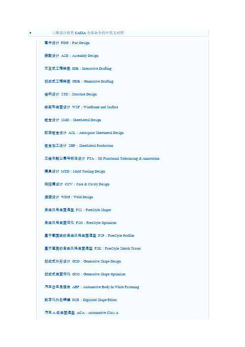
2轴半加工PMG:Prismatic Machining
3轴曲面加工SMG:3 Axis Surface Machining
多轴曲面加工MMG:Multi-Axis Surface Machining
DMU漫游器DMN:DMNDMU Navigator
DMU运动机构模拟KIN:DMU Kinematics Simulator
DMU空间分析SPA:DMU Space Analysis
DMU装配模拟FIT:DMU Fitting Simulator
DMU优化器DMO:DMU Optimizer
DMU工程分析审查ANR:DMU Engineering Analysis Review
Elfini结构分析EST:Elfini Solver Verification
电路板设计CBD:Circuit Board Design
电气系统功能定义EFD:Electrical System Functional Definition
电气元件库管理员ELB:Electrical Library
HVAC图表设计HVD:HVAC Diagrams
电气连接原理图设计ELD:Electrical Connectivity Diagrams
系统原理图设计SDI:Systems Diagrams
管线原理图设计TUD:Tubing Diagrams
波导设备原理图设计WVD:Waveguide Diagrams
钣金设计SMD:SheetMetal Design
航空钣金设计ASL:Aerospace Sheetmetal Design
史上最全的CATIA主模块介绍
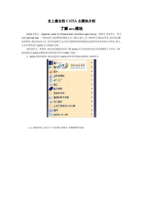
史上最全的CATIA主模块介绍了解CATIA模块CATIA是英文 Computer Aided Tri-Dimensional Interface Application 的缩写.是世界上一种主流的CAD/CAE/CAM 一体化软件.他的模块的数量之多,功能之强大,在三维软件中都是佼佼者.面对如此繁杂的软件,我们该从何入手,从何学起呢?又怎么样才能够学好呢?我相信这是所有初学者的心中所问.那么,让本站带你进行CATIA学习的新纪元吧.我们要学习一种软件,就应该对他做初步的了解.CATIA在不同需求时是在不同的模块下工作的.下面我们就先对CATIA的模块进行简单的介绍(以V5R17为例):1.CATIA的基本框架:此部分提供出CATIA的所有的基础功能模块,如图所示:1.1基础结构:它包含了产品结构,材料库,库编辑器等功能.1.2机械设计:包含机械设计中的以下单元:1.3形状(造型):提供曲面和逆向工程设计单元,可以自由塑造不规则曲面,也可以用草图来构建曲面.1.4分析与模拟:提供实体的网格划分与静力,共振等有限元分析功能,并且可以输出网格分割数据供其他分析软件使用.1.5AEC工厂:提供工厂的规划建设功能.1.6加工: 包含从两轴到五轴的加工编程的能力,并且支持快速原型功能.1.7数字模型:包含动态机构仿真,装配配合空间分析,产品功能分析与功能优化等.1.8设备与系统:提供各种系统设备的建置,管路和电线的配置以及电子零件配置等功能.1.9制造的数字处理:提供在三维空间中进行产品的特征,公差与配合标注等功能.1.10 加工模拟: 通过对数控机床的实体建模、组装和整机模拟,实现数控加工过程的仿真.1.11 人机工程学设计与分析:提供人体模型,并且可以对产品进行人体空间分析.1.12 智件:包含知识顾问,知识工程专家和产品工程优化等单元.1.13 ENOVIA V5 VPM:产品生命周期并行产品过程及开发管理工具2.常用模块:这部分是由用户自己根据自己的需要进行选择的,选择后模块显示在菜单中,例如:3.由于绝大多数的用户使用的都是中文界面的CATIA,我们下面就将所有的模块按照中文名称,英文简写,以及英文名称的顺序罗列下来:零件设计 PDG:Part Design装配设计 ASD:Assembly Design交互式工程绘图 IDR:Interactive Drafting创成式工程绘图 GDR:Generative Drafting结构设计 STD:Structure Design线架和曲面设计 WSF:Wireframe and Surface钣金设计 SMD:SheetMetal Design航空钣金设计 ASL:Aerospace Sheetmetal Design钣金加工设计 SHP:SheetMetal Production三维功能公差与标注设计 FTA:3D Functional Tolerancing & Annotation模具设计 MTD:Mold Tooling Design阴阳模设计 CCV:Core & Cavity Design焊接设计 WDG:Weld Design自由风格曲面造型 FSS:FreeStyle Shaper自由风格曲面优化 FSO:FreeStyle Optimizer基于截面线的自由风格曲面造型 FSP:FreeStyle Profiler基于草图的自由风格曲面造型 FSK:FreeStyle Sketch Tracer创成式外形设计 GSD:Generative Shape Design创成式曲面优化 GSO:Generative Shape Optimizer汽车白车身接合 ABF:Automotive Body In White Fastening数字化外形编辑 DSE:Digitized Shape Editor汽车A级曲面造型 ACA:Automotive Class A快速曲面重建 QSR:Quick Surface Reconstruction创成式零件结构分析 GPS :Generative Part Structural Analysis创成式装配件结构分析 GAS :Generative Assembly Structural Analysis变形装配件公差分析 TAA:Tolerance Analysis of Deformable AssemblyElfini 结构分析 EST:Elfini Solver Verification电路板设计 CBD:Circuit Board Design电气系统功能定义 EFD:Electrical System Functional Definition电气元件库管理员 ELB:Electrical Library电气线束安装 EHI:Electrical Harness Installation电气线束布线设计 EWR:Electrical Wire Routing电气线束展平设计 EHF:Electrical Harness Flattening管路和设备原理图设计 PID:Piping & Instrumentation Diagrams HVAC 图表设计 HVD:HVAC Diagrams电气连接原理图设计 ELD:Electrical Connectivity Diagrams系统原理图设计 SDI:Systems Diagrams管线原理图设计 TUD:Tubing Diagrams波导设备原理图设计 WVD:Waveguide Diagrams系统布线设计 SRT:Systems Routing系统空间预留设计 SSR:Systems Space Reservation电气缆线布线设计 ECR:Electrical Cableway Routing设备布置设计 EQT:Equipment Arrangement线槽与导管设计 RCD:Raceway & Conduit Design波导设备设计 WAV:Waveguide Design管路设计 PIP:Piping Design管线设计 TUB:Tubing DesignHVAC设计 HVA:HVAC Design支架设计 HGR:Hanger Design结构初步布置设计 SPL:Structure Preliminary Layout结构功能设计 SFD:Structure Functional Design设备支撑结构设计 ESS:Equipment Support Structures厂房设计 PLO Plant Layout数控加工审查 NCG:NC Manufacturing Review数控加工验证 NVG:NC Manufacturing Verification2轴半加工准备助手 PMA:Prismatic Machining Preparation Assistant 2轴半加工 PMG:Prismatic Machining3轴曲面加工 SMG:3 Axis Surface Machining多轴曲面加工 MMG:Multi-Axis Surface Machining车削加工 LMG:Lathe Machining高级加工 AMG:Advanced Part MachiningSTL快速成型 STL:STL Rapid Prototyping知识工程顾问 KWA:Knowledge Advisor知识工程专家 KWE:Knowledge Expert产品工程优化 PEO:Product Engineering Optimizer产品知识模板 PKT:Product Knowledge Template业务流程知识模板 BKT:Business Process Knowledge Template产品功能定义 PFD:Product Function Definition产品功能优化 PFO:Product Function OptimizerDMU 漫游器 DMN:DMNDMU NavigatorDMU 运动机构模拟 KIN:DMU Kinematics SimulatorDMU 空间分析 SPA:DMU Space AnalysisDMU装配模拟 FIT:DMU Fitting SimulatorDMU优化器 DMO:DMU OptimizerDMU工程分析审查 ANR:DMU Engineering Analysis Review DMU空间工程助手 SPE:DMU Space Engineering Assistant 人体模型构造器 HBR:Human Builder人体模型测量编辑 HME:Human Measurements Editor人体姿态分析 HPA:Human Posture Analysis人体行为分析 HAA:Human Activity Analysis。
CATIAV5装配设计(AssemblyDesign)

CATIAV5装配设计(AssemblyDesign)CATIA V5 装配设计(Assembly Design)CATIA V5 装配设计(Assembly Design)是帮助设计师用自上而下或自下而上的方法定义和管理多层次的大型装结构。
3.1 相关的图像菜单3.1.1产品结构工具(Product Structure Toolbar)Inserting a New Component:将新元件插入一个已有的装配中,此子装配的名字不存盘Inserting a New Product:将新产品插入一个已有的装配中,此子装配的名字存盘Inserting a New Part:将新零件插入一个已有的装配中Inserting Existing Components:将存在的子装配插入一个已有的装配中Replacing Components:替换元件Reordering the Tree:在结构树上重新安排子装配的位置Generating Numbers:生成产品子装配的编号Product Initialization:产品初始化Unload Components :卸载子装配Load Components:加载子装配Isolate Part:孤立零件Deactivate Component:不激活子装配Activate Component:激活子装配Change Context:改变前后关系Fast Multi-Instantiation:快速多重引用Defining a Multi-Instantiation:定义多重引用Symmetry:镜像Manage Representations:管理产品的几何描述Design Mode:设计模式Visualization Mode:显示模式Deactivate a Node:不激活一个节点Activate a Node:激活一个节点Deactivate a Terminal Node:不激活一串节点Activate a Terminal Node:激活一串节点3.1.2 移动工具(Move Toolbar)Manipulating a Component:偏移或旋转子装配Snap Move:快速移动Smart Move:聪明移动Exploding an Assembly:爆炸图3.1.3 约束工具(Constraints Toolbar)Coincidence Constraint:同轴约束Contact Constraint:接触约束Offset Constraint:偏移约束Angle Constraint:角度约束Fixing a Component:固定一个子装配Fixing Components Together:子装配固定在一起Quick Constraint Command:快速约束命令Flexible Sub-Assemblies:柔性子装配Changing Constraints:改变约束Reuse Pattern:重复使用图样Deactivate Constraints:不激活约束Activate:激活约束3.1.4 更新工具(Update Toolbar)Update an Assembly:更新一个装配Update One Constraint Only:只更新约束3.1.5 约束创建模式工具(Constraint Creation Mode T oolbar) Default mode:默认模式Chain mode:链模式Stack mode:堆积模式3.1.6 注解工具(Annotations Toolbar)Text With Leader:带引出箭头的标注Flag Notes:超级链接3.1.7 装配特征工具(Assembly Features Toolbar)Assembly Split:装配切Assembly Hole:装配孔Assembly Pocket:装配凹坑Assembly Add:装配加Assembly Remove:装配减3.1.8 利用装配工具(Using Assembly Tools)Product Management:产品管理3.1.9分析工具(Analyze Tools)Bill of Material: 零件清单Analyze Updates:分析更新Analyze Constraints:分析约束Analyze Degrees of Freedom:分析自由度Analyze Dependences:分析依赖Compute Clash:计算干涉3.2 装配环境参数设定为了充分发挥CATIA V5的装配设计能力,必须根据设计对象的特点,合理地设定装配环境参数。
catia各个模块介绍(最新整理)

CATIA各个模块信息零件设计PDG:Part Design装配设计ASD:Assembly Design交互式工程绘图IDR:Interactive Drafting创成式工程绘图GDR:Generative Drafting结构设计STD:Structure Design线架和曲面设计WSF:Wireframe and Surface钣金设计SMD:SheetMetal Design航空钣金设计ASL:Aerospace Sheetmetal Design钣金加工设计SHP:SheetMetal Production三维功能公差与标注设计FTA:3D Functional Tolerancing & Annotation 模具设计MTD:Mold Tooling Design阴阳模设计CCV:Core & Cavity Design焊接设计WDG:Weld Design自由风格曲面造型FSS:FreeStyle Shaper自由风格曲面优化FSO:FreeStyle Optimizer基于截面线的自由风格曲面造型FSP:FreeStyle Profiler基于草图的自由风格曲面造型FSK:FreeStyle Sketch Tracer创成式外形设计GSD:Generative Shape Design创成式曲面优化GSO:Generative Shape Optimizer汽车白车身接合ABF:Automotive Body In White Fastening数字化外形编辑DSE:Digitized Shape Editor汽车A级曲面造型ACA:Automotive Class A快速曲面重建QSR:Quick Surface Reconstruction创成式零件结构分析GPS :Generative Part Structural Analysis创成式装配件结构分析GAS :Generative Assembly Structural Analysis 变形装配件公差分析TAA:Tolerance Analysis of Deformable Assembly Elfini 结构分析EST:Elfini Solver Verification电路板设计CBD:Circuit Board Design电气系统功能定义EFD:Electrical System Functional Definition电气元件库管理员ELB:Electrical Library电气线束安装EHI:Electrical Harness Installation电气线束布线设计EWR:Electrical Wire Routing电气线束展平设计EHF:Electrical Harness Flattening管路和设备原理图设计PID:Piping & Instrumentation DiagramsHVAC 图表设计HVD:HVAC Diagrams电气连接原理图设计ELD:Electrical Connectivity Diagrams系统原理图设计SDI:Systems Diagrams管线原理图设计TUD:Tubing Diagrams波导设备原理图设计WVD:Waveguide Diagrams系统布线设计SRT:Systems Routing系统空间预留设计SSR:Systems Space Reservation电气缆线布线设计ECR:Electrical Cableway Routing设备布置设计EQT:Equipment Arrangement线槽与导管设计RCD:Raceway & Conduit Design波导设备设计WAV:Waveguide Design管路设计PIP:Piping Design管线设计TUB:Tubing DesignHVAC设计HVA:HVAC Design支架设计HGR:Hanger Design结构初步布置设计SPL:Structure Preliminary Layout结构功能设计SFD:Structure Functional Design设备支撑结构设计ESS:Equipment Support Structures厂房设计PLO Plant Layout数控加工审查NCG:NC Manufacturing Review数控加工验证NVG:NC Manufacturing Verification2轴半加工准备助手PMA:Prismatic Machining Preparation Assistant 2轴半加工PMG:Prismatic Machining3轴曲面加工SMG:3 Axis Surface Machining多轴曲面加工MMG:Multi-Axis Surface Machining车削加工LMG:Lathe Machining高级加工AMG:Advanced Part MachiningSTL快速成型STL:STL Rapid Prototyping知识工程顾问KWA:Knowledge Advisor知识工程专家KWE:Knowledge Expert产品工程优化PEO:Product Engineering Optimizer产品知识模板PKT:Product Knowledge Template业务流程知识模板BKT:Business Process Knowledge Template产品功能定义PFD:Product Function Definition产品功能优化PFO:Product Function OptimizerDMU 漫游器DMN:DMNDMU NavigatorDMU 运动机构模拟KIN:DMU Kinematics SimulatorDMU 空间分析SPA:DMU Space AnalysisDMU装配模拟FIT:DMU Fitting SimulatorDMU优化器DMO:DMU OptimizerDMU工程分析审查ANR:DMU Engineering Analysis ReviewDMU空间工程助手SPE:DMU Space Engineering Assistant人体模型构造器HBR:Human Builder人体模型测量编辑HME:Human Measurements Editor人体姿态分析HPA:Human Posture Analysis人体行为分析HAA:Human Activity Analysis装配设计(ASS)CATIA装配设计可以使设计师建立并管理基于3D零件机械装配件。
CATIA焊接教程

这是我做的welding 入门教材。
如果可以的话,请大家多支持一下。
谢谢。
1.建新product,insert 两个新零件,赋予材料(Steel)。
如图,加入装配关系。
一个mate,一个0 offset,一个40mm offset。
2.转到weld design 工作台。
增加一个Single V butt weld。
点击Single V butt weld 命令。
3.对话框如下:Weld Name是可自定义的特征名。
图中为缺省名。
Width(b): 是两块板中间焊料的最小的基本焊缝宽度。
Height (c):是基本焊缝的高度,最小焊缝的高度。
Angle(a)是焊缝向外扩展的角度,能够增加强度,和有利于焊料的进入。
Shape 有几种选择:undefined:不定义。
Flat:平的。
Convex:突起。
Concave:凹陷。
Smooth:平滑的。
Offset:是凸起或凹陷的值。
这里选取凸起1mm。
Trimming 类似板金,可以通过它来限制焊接缝的长度。
接缝有两个端点,可以分别设定焊缝的起始和终点相对偏移量。
这里先取0。
Preparation mode 是指定板料预加工的方式。
所谓预加工就是焊接前的对焊接区域的处理,象倒角等。
With Propagation 是倒角一直延伸到零件的边缘。
Without propagation 是倒角没有延伸,刚好为焊缝的区域。
这里选为With propagation。
Geometric Elements 是定义焊接的几何元素。
这里选择两条邻近的边就可以了。
焊缝的开口将在这两条边上。
Material 选择Copper。
点击OK。
4.双击Weld.1,打开对话框,改为without propagation,点击OK。
5. 双击weld.1 打开对话框,改为with propagation。
改变trimming 的first limit和second limit值为,5mm。
CATIA三维焊点管理规范

6
由于在车身制造中存在着同工位多工序、夹具分级夹紧的操作可能,故在结构中有存在着三层板搭接处进行两层板焊接的情况,焊点易造成工程人员混淆。此类焊点在遵循上诉焊点格式要求的同时,需再加入焊接件的零部件代号加以区分,如图7。
图7同级多序焊点结构树示例
GB/T 19867.5-2008《电阻焊焊接工艺规程》
JB/T 3947-1999《电阻点焊电极接头》
3
为满足PDM文件管理系统需求,发布的CATIA焊点数模需为单独文件,通过装配在结构数模中体现。点焊、塞焊、CO2焊接而成的总成必须在三维数模中标注相应的焊接标记并建立专门的焊点描述文件,并具有版本号等属性
4
4
命名为:Part Number-Weld
例 如:W101-2801010-Weld
其 中:W101-2801010为零部件编号,Weld表示文件为焊点文件。
中文名:总成名称-焊点。
例 如:车架分总成-焊点
4
a)两层板焊点用φ6圆形和一根直线来表示,如图1左图。
b)三层板焊点用φ6圆形和两个交叉线来表示,如图1中图。
二氧化碳保护焊缝
焊缝线条
图5焊点文件的结构树构成
4
焊点线条调用超级副本生成。
见附件:Two.CATPart、Three.CATPart、Multi.CATPart。
4
焊点中心需保留,且位于焊接位置中心面。
焊点线条和中心点需保留为非参数据,除此之外所有过程数据不保留。
5
焊点数模在装配中隶属于对应的总成数模,如图6。
图3塞焊断面示意图
4
CO2焊缝采用焊缝边缘线条,颜色同上,粗细使用八型2.6mm,如图4。
图4CO2焊缝示意图
CaTia菜单英语翻译2
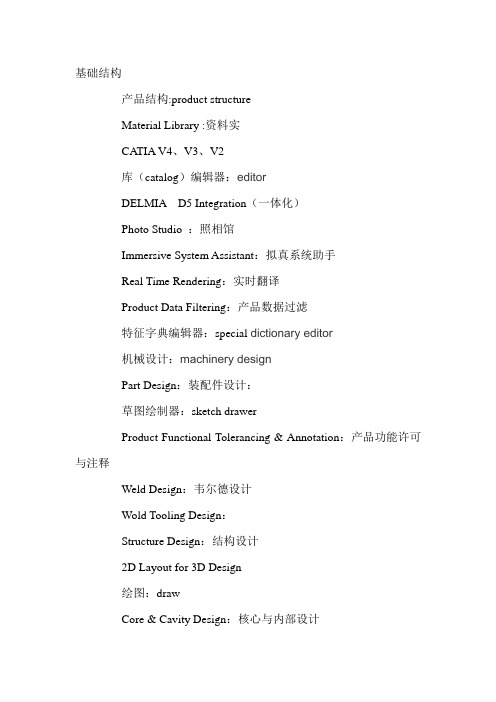
基础结构产品结构:product structureMaterial Library :资料实CA TIA V4、V3、V2库(catalog)编辑器:editorDELMIA D5 Integration(一体化)Photo Studio :照相馆Immersive System Assistant:拟真系统助手Real Time Rendering:实时翻译Product Data Filtering:产品数据过滤特征字典编辑器:special dictionary editor机械设计:machinery designPart Design:装配件设计:草图绘制器:sketch drawerProduct Functional Tolerancing & Annotation:产品功能许可与注释Weld Design:韦尔德设计Wold Tooling Design:Structure Design:结构设计2D Layout for 3D Design绘图:drawCore & Cavity Design:核心与内部设计Healing Assistant:希林助理Functional Molded Part:功能模塑部分Sheet Metal Design:金属片设计Sheet Metal Production:金属产品Composites Design:模块设计Wireframe and Surface Design:线框图和表面设计Generative Sheetmetal Design:生产金属片设计形状FreeStyle自由式Sketch Tracer:草图Imagine & Shape:形象与形状Digitized Shape Editor:数字化形状编辑Generative Shape Design:生产形状设计Quick Surface Reconstruction快速表面恢复Automotive (自动的)Class AShape Sculptor分析与模拟Advanced Meshing Tools先进结网设计Generative Structural Analysis:生产结构分析AEC 工厂Plant Layout:植物结构加工Lathe Machining:车床机器Prismatic Machining:棱镜机Surface Machining:表面机器Advanced Machining:先进机器NC Manufacturing Review:生产检查STL Rapid Prototyping:快速雏型数字模型DMU Navigator:领航员DMU Space Analysis:表面分析DMU Kinematics:运动学DMU Fitting:匹配DMU 二维查看器DMU Fastening ReviewDMU 优化器DMU 公差审查设备与系统Electrical Cabling Discipline:电动电缆行业Electrical Connectivity Diagrams:电气连接图Conduit Design管道设计Raceway Design:跑道设计Electrical Cableway Routing:电缆布线波导图形Waveguide Design:波导设计Electrical Wiring Discipline:电线专业Electrical Assembly Design:电动装配设计Electrical Part Design:电动部位设计Electrical Harness Assembly:电动捆束组件Electrical Harness Installation:电气线束安装Electrical Wire Routing:电线路由Electrical Harness Flattening:电气线束展平Electrical 3D Design Assembly:电动3D 设计安装Electrical 3D Design Part:电动3D设计部位HV AC DisciplineHV AC Diagrams:HV AC 图表HV AC Design:HVAC设计Multi-DisciplineEquipment Arrangement:器材管理Hanger Design:悬挂设计Preliminary Layout:初始结构Systems Space Reservation:系统空间保留Systems Routing:系统途径Piping Discipline:管道专业Piping and Instrumentation Diagrams:管道和仪表图Piping Design管道设计Tubing Discipline:管道专业Tubing Diagrams:管道图标Tubing Design:管道设计Structure Discipline:结构专业Structure Preliminary Layout:初始结构Structure Functional System Design:结构功能系统设计Structure functional object design:结构功能对象设计Structure Detail System Design:结构细节系统设计Structure Detail Object Design:结构细节对象设计Compartment and Access:隔室和存取Equipment Support Structures:设备支持结构Circuit Board Design:电路板设计加工的数字进程DPM – Work Instructions:DPM 工作指导Process Tolerancing & Annotation:过程许可虚注释加工模拟NC 机器模拟:machinerary imitationNC 机器工具构建器:machinerary tool builder人机工程学设计与分析Human Measurements Editor:人体模型测量编辑Human Activity Analysis:人体模型活动分析Human Builder:人体模型构建者Human Posture Analysis:人体模型分析智件Knowledge Advisor:知识顾问Knowledge Expert:知识专家Product Engineering Optimizer:产品工程优化Product Knowledge Template:产品知识模板Product Function Optimization:产品功能最优化Product Function Definition:产品功能定义ENOVIA V5 VPMVPM 游览器。
CATIA-V5-装配设计基础讲述

CATIA V5 Training
Contraints creation 装配约束生成方式: 选择(Use any geometry)选项:你能够选择任何几何元素约束。 选择(Use published geometry of child components only) 选项:你仅能够选择子 部件中已经发布的元素。 选择(Use published geometry of any level) 选项:你能够选择任何已发布元素, 不论它们处于装配的哪个级别。
CATIA V5 Training
CATIA V5 装配设计
Assembly Design
CATIA V5 Training
一、进入装配模块的方法:
(1)Start菜单
(2)File-新建Drawing
二、概念介绍
CATIA V5 Training
零件:零件是最基本的装配单位,是特征树上显示的最后一级独立的几何体文件。 组件:组件由零件和(或)其它组件组成。组件可以是几个零件构成的子装配,也可以是
(Angle)复选框里可以健入一个角度值。 Planar angle:可以选择一根轴进行角度约束,但是这根轴必须是两个平面的交线。
CATIA V5 Training
5、空间固定约束(Fix Component) 空间固定约束分为空间绝对位置固定(根据装配折几何原点进行固定)和空间相对位置的固定(要 据其他组件的相对位置对行固定)。这两种方法的切换在于Fix对话框中的Fix in Space复选框。 (1)空间绝对位置固定。选择要固定的部件后,在部件上将出现绿色的锚形图标,产品特征树上 出现锚形图标,其左下方的锁形标志表示这是1)产品结构选项: 打开Tools>Option选项后,选择Infrastructure>Product Structure选项。
(WD1)焊接资料 CATIA

Mechanical DesignCATIA - Weld DesignDesign advanced welded products based on process definition and rules.Product overviewCATIA - Weld Design 1 (WD1) is anapplication addressing welded assemblies.15 weld types (ISO standard) are provided tothe user to create welds, part preparation andrelevant annotations.This product addresses Machinery & toolingindustries through advanced weldingprocesses. The creation of the weld in the 3Ddigital Mock-Up will allow designer to manage digital pre-assembly, mass inertia, spacereservation and drafting annotation.Product Highlights Creates welding operations from a catalogue of 15 welding bead shapes (1fillet/7groove and 7 double bead) andpreparations based on ISO standards.Automatically chamfers parts and edgesin preparation for welding Creates associative features between parts and specification for ease ofmodification.User Define Weld All weld features are integrated into the 3D design: Mass inertia, space reservation therefore improving confidence and qualityfinished product.The weld visualization and specification is displayed in the drafting environment for full documentation.Product Key Customers Benefits A dedicated workbench for CATIA WeldDesign 1 (WD1) ... including AssemblyDesign 1 relevant toolbars and a dedicatedwelding toolbar. As the CATIA Weld Design 1(WD1) product is focused on weldedassemblies, user has in a single workbench all the tools to deal with the whole assembly welding process.A set of productive and intuitive tools to create welding operation... User is guided through the specification of the welding process thanks to an intuitive and interactive dialog box. Depending on the weld type, he is invited to select 2 to 4 geometries. Then,welded elements are automatically created,and can be easily modified through the same smart interface.Automatic preparation of the parts to be welded... Depending on the type of weld user chooses and the specifications hepreviously defined, CATIA - Weld Design 1(WD1) will automatically prepare the partsto be welded, creating associativeassembly features in addition to the weldMock-up. physical element. Length of preparationcan be controlled by the user, it allows toweld several parts on the same edge of agiven part. The preparation can optionallybe achieved on the contact zone on thewelded part, instead of the whole edge.Associative 3D geometry and 2Dannotations preserving design intent...created with CATIA - Weld Design 1 (WD1)generate 3D geometry and 2D annotations.User can design his weld with full flexibilityand advanced productivity, because hegets a full consistent associativity (weldcreation and preparation) in case ofmoving, replacing, deleting or modifyingparts.User Define Weld for a completeThis ability gives user the ability to declareany part as a representation of weld. Theadvantage is that user can create anon-standard weld but the system willhandle it as a weld. So that, it will beconsidered for drafting, mass, inertia,material application and all downstreamuse of welding elements.Integration within Drafting... Welds areautomatically generated in the views,section views and section cuts andimpacted by the Hidden Line Removalvisualization mode of the assembly. 2DWelds annotations are also automaticallycreated.Integration within 3D Design... Mass andinertia of the weld ribbons are added to themass and the inertia of the whole assemblyso that User, specifying the weld material,can perform relevant calculation. Weldscan also be integrated in the clash collisionof the assembly. The weld attributes canbe taken into account in Knowledgewareproducts as geometric parameters (length,width) or technological parameters(quality). CATIA - Weld Design 1 (WD1)gives user advanced design productivityand a reliable way to incorporate the weldprocess into the global 3D assemblydesign and its integration in the DigitalOther imagesABOUT CATIA V5R18CATIA is Dassault Systemes' PLM solution for digital product definition and simulation. /CATIAFor more information about our products visit /contact。
CATIA焊接结构教程(英文版)

Clash collision Welds will be integrated in the clash collision of the assembly. The way to integrate welds in the computation depends on the geometry integration in the assembly.
5
Workbench identity and contents
Workbench icon
Weld types toolbar and new commands
Example of user interface for the U Groove weldnce through UDF-like viewer 2 to 4 geometries to select, depending on type
15
Material Assignment
Assign a material to the weld : Modifiable at creation and edition One Result Part = One material Modifiable Result Part’s prefix default prefix = Material name Standard drafting pattern (cut view)
16
User Weld
The user can create his own weld. The user creates the shape of the weld bead in a part (any kind of geometry), and a weld annotation in the assembly (and optionally assembly features to handle preparation) . The designer creates a user weld to integrate this shape and the annotation in the weld model and the weld report : this kind of weld is manageable as any “native” weld.
(完整版)catia各个模块介绍

CATIA各个模块信息零件设计PDG:Part Design装配设计ASD:Assembly Design交互式工程绘图IDR:Interactive Drafting创成式工程绘图GDR:Generative Drafting结构设计STD:Structure Design线架和曲面设计WSF:Wireframe and Surface钣金设计SMD:SheetMetal Design航空钣金设计ASL:Aerospace Sheetmetal Design钣金加工设计SHP:SheetMetal Production三维功能公差与标注设计FTA:3D Functional Tolerancing & Annotation 模具设计MTD:Mold Tooling Design阴阳模设计CCV:Core & Cavity Design焊接设计WDG:Weld Design自由风格曲面造型FSS:FreeStyle Shaper自由风格曲面优化FSO:FreeStyle Optimizer基于截面线的自由风格曲面造型FSP:FreeStyle Profiler基于草图的自由风格曲面造型FSK:FreeStyle Sketch Tracer创成式外形设计GSD:Generative Shape Design创成式曲面优化GSO:Generative Shape Optimizer汽车白车身接合ABF:Automotive Body In White Fastening数字化外形编辑DSE:Digitized Shape Editor汽车A级曲面造型ACA:Automotive Class A快速曲面重建QSR:Quick Surface Reconstruction创成式零件结构分析GPS :Generative Part Structural Analysis创成式装配件结构分析GAS :Generative Assembly Structural Analysis 变形装配件公差分析TAA:Tolerance Analysis of Deformable Assembly Elfini 结构分析EST:Elfini Solver Verification电路板设计CBD:Circuit Board Design电气系统功能定义EFD:Electrical System Functional Definition电气元件库管理员ELB:Electrical Library电气线束安装EHI:Electrical Harness Installation电气线束布线设计EWR:Electrical Wire Routing电气线束展平设计EHF:Electrical Harness Flattening管路和设备原理图设计PID:Piping & Instrumentation Diagrams HVAC 图表设计HVD:HVAC Diagrams电气连接原理图设计ELD:Electrical Connectivity Diagrams系统原理图设计SDI:Systems Diagrams管线原理图设计TUD:Tubing Diagrams波导设备原理图设计WVD:Waveguide Diagrams系统布线设计SRT:Systems Routing系统空间预留设计SSR:Systems Space Reservation电气缆线布线设计ECR:Electrical Cableway Routing设备布置设计EQT:Equipment Arrangement线槽与导管设计RCD:Raceway & Conduit Design波导设备设计WAV:Waveguide Design管路设计PIP:Piping Design管线设计TUB:Tubing DesignHVAC设计HVA:HVAC Design支架设计HGR:Hanger Design结构初步布置设计SPL:Structure Preliminary Layout结构功能设计SFD:Structure Functional Design设备支撑结构设计ESS:Equipment Support Structures厂房设计PLO Plant Layout数控加工审查NCG:NC Manufacturing Review数控加工验证NVG:NC Manufacturing Verification2轴半加工准备助手PMA:Prismatic Machining Preparation Assistant 2轴半加工PMG:Prismatic Machining3轴曲面加工SMG:3 Axis Surface Machining多轴曲面加工MMG:Multi-Axis Surface Machining车削加工LMG:Lathe Machining高级加工AMG:Advanced Part MachiningSTL快速成型STL:STL Rapid Prototyping知识工程顾问KWA:Knowledge Advisor知识工程专家KWE:Knowledge Expert产品工程优化PEO:Product Engineering Optimizer产品知识模板PKT:Product Knowledge Template业务流程知识模板BKT:Business Process Knowledge Template产品功能定义PFD:Product Function Definition产品功能优化PFO:Product Function OptimizerDMU 漫游器DMN:DMNDMU NavigatorDMU 运动机构模拟KIN:DMU Kinematics SimulatorDMU 空间分析SPA:DMU Space AnalysisDMU装配模拟FIT:DMU Fitting SimulatorDMU优化器DMO:DMU OptimizerDMU工程分析审查ANR:DMU Engineering Analysis ReviewDMU空间工程助手SPE:DMU Space Engineering Assistant人体模型构造器HBR:Human Builder人体模型测量编辑HME:Human Measurements Editor人体姿态分析HPA:Human Posture Analysis人体行为分析HAA:Human Activity Analysis装配设计(ASS)CATIA装配设计可以使设计师建立并管理基于3D零件机械装配件。
- 1、下载文档前请自行甄别文档内容的完整性,平台不提供额外的编辑、内容补充、找答案等附加服务。
- 2、"仅部分预览"的文档,不可在线预览部分如存在完整性等问题,可反馈申请退款(可完整预览的文档不适用该条件!)。
- 3、如文档侵犯您的权益,请联系客服反馈,我们会尽快为您处理(人工客服工作时间:9:00-18:30)。
X REF
Preparation Relimitation
fillet
Height
2 Faces
N
Y
square
Length
Edge + (Edge or
groove (root opening)
Fac#43; (Edge or
V groove
Angle
Face)
Y
Y
bevel groove
Y
Edge + (Edge or
J groove
Radius
Face)
Y
Y
Drafting Y Y Y Y Y Y Y Y
Type C R1 R2 R2 R2 R2 R2 R2
© 1997 – 2001 DASSAULT SYSTEMES
DASSAULT SYSTEMES - Date Page 4
Weld Design 1 (WD1)
Added Value in V5R11
© 1997 – 2001 DASSAULT SYSTEMES
Agenda
➢ Weld Design 1 - V5R11 Assessment ➢ Key V5R11 Highlights
DASSAULT SYSTEMES - Date Page 2
Angle
Edge + (Edge or Face)
Y
Y
Edge + (Edge or
Y groove Angle, height
Face)
Y
Y
Edge + (Edge or
groove Angle, height
Face)
Y
Y
U groove
Radius
Edge + (Edge or Face)
Y
Product Contents
The different planned type of modification:
MODIFICATION
SYMBOL
NAME FFalaltt
PARAMETERS -
Convex
height
Concave Backing run
height height
Coming later
DASSAULT SYSTEMES - Date Page 6
Update behavior
Welds generate 3D geometry and 2D annotations. To ensure the results associativity, welds are integrated to the update as assembly features. Welds will be impacted when :
© 1997 – 2001 DASSAULT SYSTEMES
DASSAULT SYSTEMES - Date Page 5
Workbench identity and contents
Workbench icon
Weld types toolbar and new commands
© 1997 – 2001 DASSAULT SYSTEMES
✓ moving parts ✓ replacing parts ✓ deleting parts ✓ modifying parts They can also be deactivated
DASSAULT SYSTEMES - Date Page 7
© 1997 – 2001 DASSAULT SYSTEMES
DASSAULT SYSTEMES - Date Page 3
© 1997 – 2001 DASSAULT SYSTEMES
Product Contents
The different planned type of weld symbols:
WELD
ANSI
SYMBOL NAME PARAMETERS
Drafting integration
Welds are integrated to the drafting by two ways: ✓ They are automatically generated in the views, section views and section cuts and impacted by the HLR of the assembly. The possibility to set automatically the pattern to the section views is to define. ✓They produce weld annotations as the “Weld Planners” method and will be integrated in the drafting by the same methodology of the “Weld Planners”
© 1997 – 2001 DASSAULT SYSTEMES
Weld Design 1 – V5R11 Assessment
Product overview & positioning reminder
Purpose/scope of the product
Weld Design 1 completes the fabrication and assembly process for industrial machinery by providing a dedicated tool for weld creation, part preparation, and making relevant annotations. The ability to create welds in the 3D digital mock-up facilitates process integration by allowing the designer to manage digital pre-assembly, mass inertia, space reservation, and drafting annotation.
Example of user interface for the U Groove weld type
Faces selection
Guidance through UDF-like viewer 2 to 4 geometries to select, depending on type
Parameters
