EMC1043中文资料
EMC1033-ACZB-TR中文资料(SMSC)中文数据手册「EasyDatasheet - 矽搜」
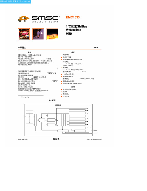
图 1.1 EMC1033引脚配置 表 1.1引脚说明
PIN NO. 1 2
3
说明
电源电压,3.0V至3.6V. 阳极连接用于远程温度二极管2远程温度二极管1和阴极连接 . 阴极连接远程温度diode1和远程温度二极管2阳极连接.
ADDR /THERM
GND ALERT /THERM2 SMDATA SMCLK
测温误差两个主要来源.
1
所述EMC1033产生具有两个单独中断
可编程热脱扣点.该
THERM 产量
工作与可编程阈值恒温器
和滞后.该
ALERT 输出可配置
作为一个屏蔽SMBus报警可编程
窗口比较器限制,或作为第二
THERM
输出.这两个中断防护持在8针
包而第三温度区中加入
反并联二极管技术.这允许
EMC1033可以在引脚与ADT7461兼容,
Corporation (“SMSC”). Product namesand company namesare the trademarksof their respective holders.
SMSC DISCLAIMS AND EXCLUDES ANY AND ALL WARRANTIES, INCLUDING WITHOUT LIMITATION ANY AND ALL IMPLIED WARRANTIES OF MERCHANTABILITY, FITNESS FOR A PARTICULAR PURPOSE, TITLE, AND AGAINST INFRINGEMENT AND THE LIKE, AND ANY AND ALL WARRANTIES ARISING FROM ANY COURSE OF DEALING OR USAGE OF TRADE.
北京四方220kV数字式线路保护装置CSC-103B系列技术说明书V1.02
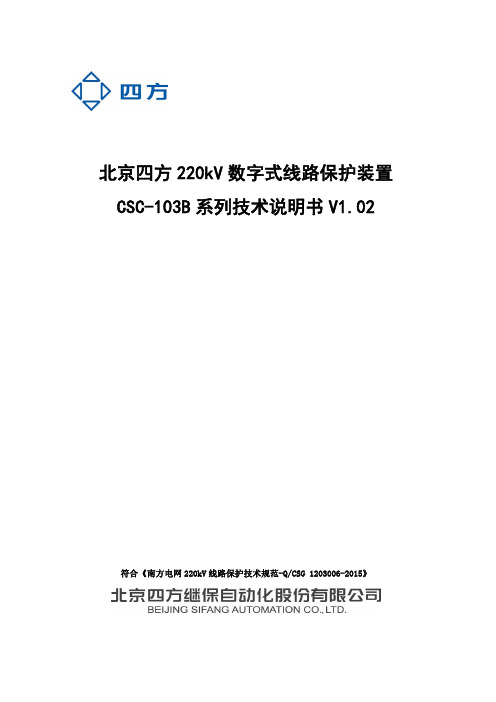
第三章 装置介绍 ..................................................... 8 3.1 概述 .......................................................... 8 3.2 技术条件 ..................................................... 10 3.2.1 环境条件 ................................................ 10 3.2.2 电气绝缘性能 ............................................ 11 3.2.3 机械性能 ................................................ 11 3.2.4 电磁兼容性 .............................................. 11 3.2.5 安全性能 ................................................ 12 3.2.6 热性能(过载能力) ...................................... 12 3.2.7 功率消耗 ................................................ 12 3.2.8 输出触点容量 ............................................ 12 3.3 装置主要技术参数 ............................................. 13
EMC Teseq NSG 3040A多功能干扰源说明书

Teseq’s new NSG 3040A is an easy-to-use multifunction generator that simulates electromagnetic interference effects for immunity testing in conformity with international, national and manufacturers’ standards including the latest IEC/EN standards. The NSG 3040A system is designed to fulfill conducted EMC test requirements for CE mark testing, which generally include combination wave surge, Electrical Fast Transient (EFT) pulses and Power Quality Testing (PQT). Extensive expansion capabilities enable the system to be configured for a much broader range of applications.Featuring an innovative, modular design, the NSG 3040A is a versatile system that can be configured for basic testing needs and expanded to meet the needs of sophisticated test laboratories.Using state-of-the-art components, the self-contained modules set new standards with respect to switching and phase accuracy and exceed the existing standards’ requirements.A 7” touch panel display with superb contrast and color makes controlling the NSG 3040A easy. For fast and efficient data entry, input devices include an integrated keyboard and a thumbwheel with additional keys for sensitivity adjustment. To achieve quick, reliable results in a development environment a standardized test can be initiated with just a few “clicks” using the integrated Test Assistance (TA) function.Convenient touch input buttons make each parameter’s value highly visible and allow the user to quickly select and modify all settings. A stylus is not necessary, and ramp functions can be programmed quickly and easily. Multi-step test procedures can be created and their sequence or parameter values can be changed easily.With expert mode users can make manual parameter changes using the thumbwheel while a test is under way, providing an effective and fast method for identifying critical threshold values. The NSG 3040A has an Ethernet port for external PC control. The Windows-based control software simplifies test programming and compilation of complex test sequences with various types of tests. Test reports can be generated during the test operation, allowing the operator to enter observations as the test progresses and increasing the efficiency of long-term tests.One box solution system Surge voltage to 4.8 kV EFT/Burst to 4.8 kV / 1 MHz PQT to 16 A / 300 VAC & DC Easy to use 7“ color touch screen Parameters can be changed while test running Wide range of optional testaccessoriesTHE SMART 4 KV SOLUTION FOR CE APPLICATIONSNSG 3040ANSG 3040ATHE SMART 4 KV SOLUTION FOR CE APPLICATIONSThe NSG 3040A performs tests according to the following specifications:Combination wave pulse 1, 2/50 - 8/20 µs (Hybrid-Surge pulse)Pulse conforms to IEC/EN 61000-4-5Parameter ValuePulse voltage (open circuit): ±200 V to 4.8 kV (in 1 V steps)Pulse current (short circuit): ±100 A to 2.4 kAImpedance: 2/12 ΩPolarity: positive / negative / alternatePulse repetition: 10 s, up to 9’999 s (in 1 s steps)Test duration: 1 to 99’999 pulses, continuousPhase synchronization: asynchronous, synchronous 0 to 359º (in 1º steps)Coupling: IEC / externalBurst (EFT) 5/50 nsPulse conforms to IEC/EN 61000-4-4Parameter ValuePulse amplitude: ±200 V to 4.8 kV (in 1 V steps) - open circuit±100 V to 2.4 kV (50 Ω matching system)Burst frequency: 100 Hz to 1000 kHzPolarity: positive / negative / alternateRepetition time: 10 ms to 9'999 msBurst duration: 0.01 ms to 9'999 ms, single pulseTest duration: 1 s to 9’999s, 1 min to 1600 min, endlessPhase synchronization: asynchronous, synchronous 0 to 359º (in 1º steps)Coupling: internal / externalNSG 3040ATHE SMART 4 KV SOLUTION FOR CE APPLICATIONSDips & Interruptsconforms to IEC/EN 61000-4-11, IEC/EN 61000-4-29Parameter ValueDips & Interrupts: From EUT voltage input to 0 V, 0% (1)Uvar with optional variac: depending on model (VAR 3005A)Uvar with step transformer: 0, 40, 70, 80% (INA 650xA)Peak inrush current capability: > 500 A (at 230 V)Switching times: 1 to 5 μs (100 Ω load)Event time (T-Event): 20 µs to 9999 s, 0.5 to 9’999 cyclesRepetition time:10 ms to 9’999 ms, 1 to 9’999 sTest duration: 1 to 99’999 events, endlessPhase synchronization: asynchronous, synchronous 0 to 359º (in 1º steps)chapt. 5.1 a test voltage level from 0% to 20% of the rated voltage is considered as a total interruption.Variation test (with VAR 3005A only)conforms to IEC/EN 61000-4-11Parameter ValueUvar with optional variac: up to approx. 265 V (in 1 V steps) or up to 115% Uin (in 1% steps)Decreasing time Td: 1 ms to 9.999 s, 0.5 to 9999 cycles, abruptTime at reduced voltage Ts: 1 ms to 9.999 s, 0.5 to 9999 cycles,Increasing time Ti: 1 ms to 9.999 s, 0.5 to 9999 cycles,Repetition time: 1 s to 9’999 sEvents: 1 to 99’999Pulsed magnetic field in conjunction with MFC 30conforms to IEC/EN 61000-4-9Parameter ValueField: 100 to 1200 A/mPolarity: positive / negative / alternateRepetition time: 10 s to 9999s (in 1 s steps)Impedance: 2 ΩCoil / impedance factor: 0.01 to 100.00Test duration: 1 to 9’999 pulses, endlessPhase synchronization: asynchronous, synchronous 0 to 359º (in 1º steps)NSG 3040ATHE SMART 4 KV SOLUTION FOR CE APPLICATIONSPower magnetic field in conjunction with MFT 30 or MFO 6501 and MFC 30 & MFC 300conforms to IEC/EN 61000-4-8Parameter ValueField: 1 to max. 40 A/mFrequency: 50 or 60 HzCoil factor: 0.01 to 100Test duration: 1 s to 99’999 s, endlessInternal coupling networkParameter ValueEUT supply: 1-phaseEUT VAC: Up to 300 Vrms *, 50 / 60 Hz (phase - neutral)EUT VDC: Up to 300 VDCEUT current 1 x 16 Arms continuous (over heat protected)Connections: Front panel:Rear panel - EUT: 4mm banana plug- Burst OUT 50 SHV- Trigger out BNC- EUT supply: banana plug 4 mm- Additional ground connector- Instrument supply 85 V to 264 VAC - Connector surge HV – COMSurge Standard coupling as per IEC 61000-4-5Coupling mode Line to LineLine(s) to groundMains decoupling: 1.5 mH 0% + 35%Decoupling attenuation: Residual pulse voltage on EUT power supply inputs 15 % max.Residual voltage on non-pulsed EUT power supply inputs 15 % max. EFT (Burst) Standard coupling all lines to ref ground (GND)IEC / EN 61000-4-4L, N, PE to ref GNDAny lines and combinatio L tto ref GND: to ref GNDN to ref GNDPE to ref GNDL, N to ref GNDL, PE to ref GNDN, PE to ref GND PQT: Dips & interrupts to phase LNSG 3040ATHE SMART 4 KV SOLUTION FOR CE APPLICATIONSTechnical specificationInstrument supply 85 to 265 VAC, 50 / 60 HzDimensions NSG 3040A: 19”; 3 HU, 448 x 154 x 500 mm (W x H x D)Weight NSG 3040A: approx. 22 kg (49 lbs)Type DescriptionCDN 3043A-C32 Three phase automatic coupling decoupling network, 3x480 V / 32 ACDN 3425 Burst EFT capacitive coupling clamp for data line couplingCDN 117A-C4-4-1 Coupling networks for unsymmetrical signal-/data lines (surge)CDN 118A-C4-4-1 Coupling networks for symmetrical signal-/data lines (surge)CDN HSS-2 Coupling network for 2 kV surge pulse 1.2 / 50 μs IEC/EN 61000-4-5on unshielded symmetrical high speed telecom lines (Ethernet)PVF BKIT 1Burst/EFT verification setMD 210 Voltage differential probe 3.5 kV / 7 kVMD 300 Current probe 5 kAType DescriptionTVT 1-250-16Manual step transformer, 16 AAC, 0/40/70/80%VAR 3005A-S16 Automatic single variable transformer, 1 x 16 AAccessories for IEC/EN 61000-4-8/-4-9AMETEK CTSSternenhofstr. 15 4153 Reinach SwitzerlandT + 41 61 204 41 11 F + 41 61 204 41 00************************© December 2018 AMETEK CTSSpecifications subject to change without notice. Teseq® is an ISO-registered company. Its products are designed and manufactured under the strict quality and environmental requirements of the ISO 9001. This document has been carefully checked. However, Teseq® does not assume any liability for errors or inaccuracies.691-387 A December 2018Type DescriptionMFO 6501A Manual magnetic field option for -4-8MFC 30 Magnetic field coil 1 x 1 m, with MFO max. 40 A/m -4-8;Surge* max. 1200 A/m -4-9MFC 300 Magnetic field coil 1 x 1 m; max. 330 A/m -4-8。
EMC分类简介及测试用例

电磁兼容(EMC)EMC包含两大项:EMI(干扰)和EMS(敏感度,抗干扰)一、EMI(Electro-Magnetic Interference)---电磁干扰测试测量被测设备在正常工作状态下产生并向外发射的电磁波信号的大小来反应对周围电子设备干扰的强弱。
EMI测试项包括:RE(Radiated Emission)-辐射干扰测试CE(Conducted Emission)-传导干扰扰测试Harmonic-谐波电流干扰测试Flicker-电压变化和闪烁测试EMI测试分类:射频、工频。
1)射频类射频分传导和辐射两项测试。
A>传导干扰(屏蔽室测试、全波暗室)注:测量DUT沿电源线向电网发射的连续骚扰电压。
传导分电压和功率两项测试:传导电压标准:CISPR11、14、15、22传导功率标准:CISPR11、14B>辐射干扰(电磁屏蔽半波暗室测试)注:测量DUT沿自由空间对外辐射的电磁波场强。
射频辐射标准:CISPR11、22、IEC605712)工频类(实验室测试)工频分谐波和闪烁两项测试工频谐波IEC6100-3-2工频闪烁IEC6100-3-3二、EMS(Electro-Magnetic Susceptibility)---电磁抗扰度测试测试是测量被测设备对电磁骚扰的抗干扰的能力强弱。
EMS 测试项包括:ESD-静电抗扰度测试RS-射频电磁场辐射抗扰度测试CS-射频场感应的传导骚扰抗扰度测试DIP-电压暂降,短时中断和电压变化抗扰度测试Surge-浪涌(冲击)抗扰度测试EFT-电快速瞬变脉冲群抗扰度测试PFMF-工频磁场抗扰度测试PMS-工频磁场搞扰度EMS测试分类:瞬变、射频、低频磁场、电源质量。
1)瞬变瞬变类测试分为静电、瞬变脉冲和浪涌三项测试。
瞬变静电IEC6100-4-2瞬变脉冲IEC6100-4-4瞬变浪涌IEC6100-4-52)射频射频分传导和辐射两项测试。
射频传导IEC61004-6(实验室测试)射频辐射IEC6100-4-3(电波暗室测试)3)低频磁场低频磁场分脉冲磁场和工频磁场两项测试脉冲磁场IEC6100-4-9工频磁场IEC6100-4-84)电源质量电源质量分跌落、中断、电压变化三项测试IEC6100-4-11ECM测试设计案例电磁兼容(EMC)是对电子产品在电磁场方面干扰大小(EMI)和抗干扰能力(EMS)的综合评定,是产品质量最重要的指标之一,电磁兼容的测量由测试场地和测试仪器组成,中包标准建立一个屏蔽室,和一套EMS测试室。
EMC基础知识

EMI的测试包括:
RE(辐射/发射) Harmonic(谐波) CE(传导干扰) Flicker (闪烁)
(谐波、闪烁用一套设备, GTS选择了EMtest品牌设备)
EMI是通过测试数据来判定结果
EMS测试项包括
ESD (静电)(静电枪) EFT(瞬态脉冲干扰) DIP (电压跌落) Surge(浪涌/雷击)
EN55013 (AV 类产品) EN55014-1 (玩具、小家电类产品) EN55015 (灯具类产品) EN55022 (通讯、IT 类产品)= GB9254
工频类测试项目: 工频类测试项目:工频分谐波和闪烁两项测试
工频谐波 EN61000-3-2 :谐波电流辐射的极限值 工频闪烁 EN61000-3-3 : 公用低压供电系统中电压波动和闪变的
欧洲RF测试标准:R&TTE指令 EN300220:航模、无线报警器、无线鼠键、遥控汽车/开关
SRD产品 (其操作頻率介于25MHz to 1000MHz)
EN300330: RFID , SRD产品
(其操作頻率介于9KHz to 25MHz)
EN300440:无线耳机、无线婴儿监视器;
SRD产品 (其操作頻率介于1GHz to 40GHz)
EN300422:无线麦克风 EN300328:蓝牙、WLAN802.11b/g/n产品,2.4GHz展頻調变
技術產品測試
EN301511:GSM手机, EN301908 :(WCDMA/CDMA2000) EN301357:FM发射器
FCC关于EMC的测试标准
FCC关于EMC的测试标准主要是 FCC Part 15,针对不同 的产品选择合适的章节。 家电、IT、AV、LED灯:FCC Part 15B 节能灯、微波炉: FCC Part 18 民用对讲机: FCC Part 95 (RF:EN300296) 专业对讲机: FCC Part 90 (RF:EN300086) 无线麦克风: FCC Part 74 (RF:EN300422) GSM&WCDMA手机: FCC Part 22H/24E 3G手机: FCC Part 27 (RF:EN301908) 电话机Part 15B /无绳电话Part 15D:FCC Part 68
油气储运工程振动光缆周界入侵报警系统技术规格书
油气储运工程振动光缆周界入侵报警系统技术规格书油气储运工程振动光缆周界入侵报警系统技术规格书摘要:本文将探讨油气储运工程中振动光缆周界入侵报警系统的技术规格书。
我们将从简单介绍到深入探讨该系统的各个方面,为读者提供全面的理解。
通过本文,读者将了解该报警系统的原理、技术要求以及适用范围,并且能够更深入地理解其在油气储运工程中的应用。
目录:1. 引言2. 系统原理3. 技术要求3.1 光缆选择3.2 报警灵敏度3.3 报警准确性3.4 系统可靠性4. 系统应用4.1 监测管道周界安全4.2 防止非法入侵4.3 预防安全事故5. 总结与展望1. 引言油气储运工程的安全至关重要,而振动光缆周界入侵报警系统能够提供有效的安全保障。
本文将介绍该系统的技术规格书,以使读者能够全面理解其原理和应用。
2. 系统原理振动光缆周界入侵报警系统利用光纤传输振动信号,并通过信号分析和处理来判断是否有入侵者。
该系统由主控制器、光源、光纤传感器和报警器等组成。
光纤传感器能够监测光缆上的振动信号,并将信号传输给主控制器进行分析。
当有入侵信号时,主控制器将触发报警器进行报警。
3. 技术要求振动光缆周界入侵报警系统具有以下技术要求。
3.1 光缆选择振动光缆应选择抗拉强度高、阻力低、对外界环境变化敏感度低的光缆。
光缆的长度应根据实际应用需求进行选择。
3.2 报警灵敏度系统的报警灵敏度应能够准确判断细微的振动信号,并排除环境噪音的干扰。
系统还应具备自适应能力,可以根据环境的变化进行调整。
3.3 报警准确性报警系统的准确性对于油气储运工程的安全至关重要。
系统应能够区分真实的入侵信号和误报信号,并能够及时准确地报警。
3.4 系统可靠性振动光缆周界入侵报警系统应具备高可靠性,能够抵抗外部干扰和恶劣环境的影响。
系统的故障率应尽可能低,且具备自动诊断和修复功能。
4. 系统应用振动光缆周界入侵报警系统在油气储运工程中有广泛的应用。
4.1 监测管道周界安全通过布设振动光缆,系统能够实时监测油气管道周围的活动情况,及时发现并报警管道周界的非法入侵行为,保障油气储运的安全。
电磁兼容(EMC)主要检测设备列表
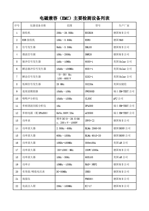
德国R/S公司
57
人工电源网络
(0~200)MHz
ESH3-Z6
德国R/S公司
58
人工电源网络
(0~200)MHz
ESH3-Z6
德国R/S公司
59
人工电源网络
(0.15~30) MHz
ENV4200
德国R/S公司
60
32A单相电源耦合网络
32A
CDN-M1/32A
瑞士EM-TEST公司
61
64
耦合去耦网络
100kHz~1000MHz
CDN-M5/32A
瑞士EM-TEST公司
65
耦合去耦网络
4线;50V/1A
CNV504N
瑞士EM-TEST公司
66
耦合去耦网络
8线;50V/1A
CNV508S1
瑞士EM-TEST公司
67
阻抗稳定网络
0.15MHz~30MHz
ENY81
德国R/S公司
68
阻抗稳定网络
9123-1N
美国Solar公司
33
ESD 模拟器
16.5kV
dito
瑞士EM-TEST公司
34
静放电模拟器
25kV;150PF/330
ESD 30C/P30C
瑞士EM-TEST公司
35
通讯浪涌发生器
(0~700)μs;4kV
TSS 500M4
瑞士EM-TEST公司
36
振铃波和阻尼振荡波发生器
250V/16A;110V/16A
(100kHz~1MHz)
OCS500 M6
瑞士EM-TEST公司
37
传导抗干扰(脉冲磁场)模拟器
ADGM1004 集成驱动器的0 Hz DC至13 GHz、 2.5 kV HBM ESD、SP

Rev. DDocument FeedbackInformation furnished by Analog Devices is believed to be accurate and reliable. However, no responsibility is assumed by Analog Devices for its use, nor for any infringements of patents or other rights of third parties that may result from its use. Specifications subject to change without notice. No license is granted by implication or otherwise under any patent or patent rights of Analog Devices. Trademarks andregistered trademarks are the property of their respective owners.One Technology Way, P .O. Box 9106, Norwood, M A 02062-9106, U.S.A.Tel: 781.329.4700 © 2017–2019 Analog Devices, Inc. All rights reserved. Technical Support /cnADI 中文版数据手册是英文版数据手册的译文,敬请谅解翻译中可能存在的语言组织或翻译错误,ADI 不对翻译中存在的差异或由此产生的错误负责。
如需确认任何词语的准确性,请参考ADI 提供的最集成驱动器的0 Hz/DC 至13 GHz 、 2.5 kV HBM ESD 、SP4T MEMS 开关数据手册ADGM1004产品特性全性能工作频率低至0 Hz/dc 导通电阻:2.9 Ω(最大值) 关断泄漏:0.5 nA (最大值) −3 dB 带宽RF1、RF4为10.8 GHz (典型值) RF2、RF3为13 GHz (典型值) RF 性能特性插入损耗:0.45 dB (典型值,2.5 GHz ) 隔离度:24 dB (典型值,2.5 GHz ) IP3:67 dBm (典型值)RF 输入功率:32 dBm (最大值) 驱动寿命:10亿周期(最小值) 密封开关触点开关导通时间:75 μs (最大值) ESD HBM 额定值5 kV (对于RF1至RF4和RFC 引脚) 2.5 kV (对于所有其他引脚) 集成驱动器,无需外部驱动器 电源电压:3.0 V 至3.6 V CMOS/LVTTL 兼容 并行和SPI 接口 独立控制开关没有电源时,开关处于开路状态要求所有RF 引脚上避免出现浮空节点(参见“浮空节点”部分) 5 mm × 4 mm × 1.45 mm 、24引脚LFCSP 工作温度范围:0°C 至+85°C应用继电器替代方案自动测试设备(ATE):RF 、数字和混合信号 负载和探针板:RF 、数字和混合信号 RF 测试仪表可重复配置型滤波器和衰减器 高性能RF 开关概述ADGM1004是一款宽带、单刀四掷(SP4T)开关,采用ADI 公司的微型机电系统(MEMS)开关技术制造而成。
电磁兼容标准与国外标准对照表EMC标准

GB 3907 83
工业无线电干扰基本测量方法
基础
CISPR16 1977
5
GB 4859 84
电气设备的抗干扰特性基本测量方法
基础
6
GB/T 15658 1995
城市无线电噪声测量方法
基础
7
GB/T
电磁兼容基本术语和定义的应用与解释
基础
IEC 61000 1 1
8
IEC 61000 1 1
低压电气及电子设备发出的谐波电流限值设备每相输入电流≤ 16A
GB/T 1999
电压暂降、短时中断和电压变化抗扰性试验
基础
IEC 61000 4 11
21
GB/T 1998
振荡波抗扰性试验
基础
IEC 61000 4 12
22
GB 8702 1988
电磁辐射防护规定
通用
23
GB/T 1992
工业过程测量和控制装置的电磁兼容性 总论
通用
IEC 801 1
24
GB/T 1992
微波炉在1GHZ以上辐射干扰测量方法
产品类
CISPR 19 1983
53
GB 6364 1986
航空无线电导航台电磁环境要求
系统间
54
GB 6830 1986
电信线路遭受强电线路危险影响的容许值
系统间
55
GB 7432 1987
同轴电缆载波通信系统抗无线电广播和通信干扰的指标
系统间
56
GB 7433 1987
CISPR 24 1997
35
GB 9383 1995
声音和电视广播接收机及有关设备传导抗扰度限值及测量方法
HMC1043 中文说明书

上海丙寅电子有限公司 网址:http://www.bingyindz.com/ 电话:086-021-65072675 传真:086-021-65075878
上海丙寅电子有限公司 网址:http://www.bingyindz.com/ 电话:086-021-65072675 传真:086-021-65075878
上海丙寅电子有限公司 网址:http://www.bingyindz.com/ 电话:086-021-65072675 传真:086-021-65075878
上海丙寅电子有限公司 网址:http://www.bingyindz.com/ 电话:086-021-65072675 传真:086-021-65075878
上海丙寅电子有限公司 网址:http://www.bingyindz.com/ 电话:086-021-65072675 传真:086-021-65075878
பைடு நூலகம்
上海丙寅电子有限公司 网址:http://www.bingyindz.com/ 电话:086-021-65072675 传真:086-021-65075878
HMC1043
BY 丙寅电子
上海丙寅电子有限公司是美国霍尼韦尔在中国区的特级代理。 在磁阻传感器应用领域有丰富的项目支持经验。提供软硬件 全套解决方案,如需要任何 Honeywell 设计与技术方面的支 持可与我们联系,将助您在最短的时间内设计成功。
上海丙寅电子有限公司 电话:86 021 65072675 传真:86 021 65075878 邮箱:by07@anotron.com 地址:中国 上海市虹口区四平路188号上海商贸大厦801室 公司主页:http://www.bingyindz.com
TJA1043简介

NXP “Clamp-30” HS-CANtransceiver TJA1043 with sleep mode and diagnosticsThis standalone HS-CAN solution, our most advanced to date, provides power supply control for the entire node and includes failsafe features, network diagnostics, and wake-up source recognition.The device exceeds the performance requirements ofISO11898-2 and ISO11898-5 and can be used in 12 and 24 V systems. It provides supply control for the entire node, using low-power Sleep and Standby modes with wake-up capabilities.It offers very low electromagnetic emission (EME), supporting reduced network ringing and choke-less operation. It also offers very high electromagnetic immunity (EMI), with typical flat ratings of 36 dBm. The behavior for all pins under all supply conditions is highly predictable, and the devicesupports multiple interface levels for use with microcontrollers operating between 3 and 5 V. A SPLIT voltage output stabilizes the recessive bus level.Low-power managementThe Standby and Sleep modes consume very little current and the device can power down the entire node while supporting local, remote, and host wake-up. The device includes wake-up source recognition and becomes “invisible” on the bus when not supplied.Key features} Exceeds ISO11898-2 and ISO11898-5} Entire node supply control via low-current Standby and Sleep modes} Listen-only mode for node diagnosis and failure containment } Suitable for 12 and 24 V systems (±58 V DC on CANH & CANL, -0,3 to 58 V on BAT)} Very low EME } Very high EMI} ±8 kV ESD performance per IEC61000-4-2} V IO input supports direct interfacing with 3 and 5 V microcontrollers} SPLIT voltage output for stabilizing the recessive bus level } Rugged reliability in the harsh automotive environment } Extensive set of protection and diagnostic functions } Automotive-qualified SO14 packageThe NXP TJA1043 is a “Clamp-30” high-speed CANtransceiver with wake-up detection and failure diagnostics. Produced in a mature silicon-on-insulator (SOI) process, it delivers improved robustness in the automotive environment and is an ideal choice for nodes that need to be available at all times, even when the internal V IO and V CC supplies are switched off.with 3rdinclude bus line short-circuit, bus dominant clamping, thermal protection and cold start (first battery connection).Improved replacement for the TJA1041/TJA1041AThe TJA1043 can be used to replace the TJA1041/TJA1041A. The TJA1043’s host wake-up capability and voltage recovery detection enhance the undervoltage recovery mechanism and, as a result, simplify the circuitry of the WAKE pin application.Protection and diagnosisThe bus pins provide ±8 kV ESD performance according to IEC61000-4-2, and both the bus pins and the battery-supply pin are protected against transients in harsh automotive environments. The Transmit Data signal (TXD) offers a dominant time-out function with diagnosis, and there issupport for TXD-to-RXD short-circuit handling with diagnosis. Undervoltage detection and recovery is available for all supply pins, including V CC , V IO , and V BAT . Other diagnostic features © 2010 NXP B.V.All rights reserved. Reproduction in whole or in part is prohibited without the prior written consent of the copyright owner. The information presented in this document does not form part of any quotation or contract, is believed to be accurate and reliable and may be changed without notice. No liability will be accepted by the publisher for any consequence of its use. Publication thereof does not convey nor imply any license under patent- or other industrial or intellectual property rights.Date of release: June 2010Document order number : 9397 750 16912Printed in the NetherlandsTJA1043 block diagramSuperior EMC performance of the TJA1043NXP’s HS-CAN transceiver portfolio。
7SJ686 以太网103协议适用版任义强

01 通用分类数据集数目(NGD) 数目::1个,计数器位::0,后续状态位::0
01 通用分类标识序号(GIN)--组号, 1D 通用分类标识序号(GIN)--条目号 01 数据类别:实际值 13 数据类型:19,带相对时间的时标报文 0A 数据宽度
01
数目
02 数据为ON 00 00 相对时间0ms, 02 00:故障序号02, 3F 0F绝对时间3909ms, 33:分钟51, 0F:小时15, 00:不知道
2.1.3 通讯链接启动:
1) UDP端口链接启动方式 装置每隔10秒钟通过UDP 端口以广播方式发送链路层心跳报文(每次发送3帧同样的心跳报文),启动链 路链接,主站收到装置心跳报文30秒钟内,应回复相应的心跳报文,以示链路层链接成功,之后进入正常 的通讯过程。正常通讯过程中,装置仍然每隔10秒钟通过UDP 端口以广播方式发送链路层心跳报文,同 样主站每隔一定的时间间隔(建议时间间隔也设为10秒钟)也要发送相应的心跳报文。如果主站或装置在 30秒钟之内没有收到对方链路层心跳报文,则认为通讯中断。 2) TCP端口链接启动方式 主站也可以每隔一定的时间间隔(时间间隔应小于30秒,建议设为10秒钟)通过TCP 端口以点对点方式主 动向装置发送链路层心跳报文,启动链路链接,装置收到主站TCP心跳报文后,会回复相应的心跳报文, 以示链路层链接成功,之后进入正常的通讯过程。正常通讯过程中,主站仍需每隔一定的时间间隔通过 TCP 端口向装置发送链路层心跳报文,装置收到心跳报文后,回复相应的心跳报文。如果主站或装置在 30秒钟之内没有收到对方链路层心跳报文,则认为通讯中断。
0A 类型标识(TYPE)::10(通用分类数据),81 可变结构限定词(VSQ)--SQ=1,Num=1 02 传送原因(COT)::1<自发(突发)> 0B 应用服务数据单元地址::11 FE 功能类型(FUN)::254(通用分类服务) F1 信息序号(INF)::241 (通用分类服务): 读一个组的全部标题的属性或值 FF 返回信息标识符(RII) 10 通用分类数据集数目(NGD) 数目::16个,计数器位::0,后续状态位::0 02 通用分类标识序号(GIN)--组号,
EMC标准对照列表
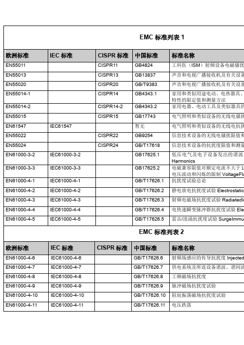
CISPR14
GB4343.1
家用和类似用途电动、电热器具、电动工具和类似设备的无线电骚扰特性的限定值和测量方法
EN55014-2
CISPR14-2
GB4343.2
家用电器、电动工具及类似器具的抗扰度
EN55015
CISPR15
GB17743
电气照明和类似设备的无线电骚扰特性的限定值和测量方法
GB/T17626.5
雷击/浪涌抗扰度试验SurgeImmunity
EMC标准列表2
欧洲标准
IEC标准
CISPR标准
中国标准
标准名称
EN61000-4-6
IEC61000-4-6
GB/T17626.6
射频场感应的传导抗扰度InjectedCurrent
EN61000-4-7
IEC61000-4-7
GB/T17626.7
EMC标准列表1
中国标准
标准名称
EN55011
CISPR11
GB4824
工科医(ISM)射频设备电磁骚扰特性的测量方法和限值
EN55013
CISPR13
GB13837
声音和电视广播接收机及有关设备电磁骚扰特性的测量方法和限值
EN55020
GB/T9383
声音和电视广播接收机及有关设备的抗扰度
供电系统及所连设备谐波、谐间波的测量和测量仪器导则
EN61000-4-8
IEC61000-4-8
GB/T17626.8
工频磁场抗扰度
EN61000-4-9
IEC61000-4-9
GB/T17626.9
脉冲磁场抗扰度试验
EN61000-4-10
瑞翁1043标准-概述说明以及解释
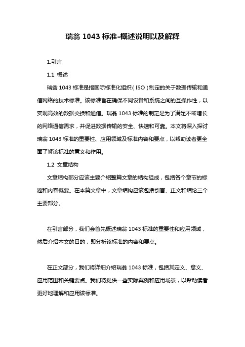
瑞翁1043标准-概述说明以及解释1.引言1.1 概述瑞翁1043标准是指国际标准化组织(ISO)制定的关于数据传输和通信网络的技术标准。
该标准旨在确保不同设备和系统之间的互操作性,以实现高效的数据交换和通信。
瑞翁1043标准的制定是为了满足不断增长的网络通信需求,并促进数据传输的安全、快速和可靠。
本文将深入探讨瑞翁1043标准的重要性、应用领域及标准内容和要点,以帮助读者更全面了解该标准的意义和作用。
1.2 文章结构文章结构部分应该主要介绍整篇文章的结构组成,包括各个章节的标题和内容概要。
在本篇文章中,文章结构应该包括引言、正文和结论三个主要部分。
在引言部分,我们会首先概述瑞翁1043标准的重要性和应用领域,然后介绍本文的目的,即分析该标准的内容和要点。
在正文部分,我们将详细介绍瑞翁1043标准,包括其定义、意义、应用范围和关键要点。
我们将提供一些实际案例和应用场景,以帮助读者更好地理解和应用该标准。
最后,在结论部分,我们将总结瑞翁1043标准的价值和重要性,展望未来该标准的发展方向,以及给出一些结论性的观点和建议。
通过这样的文章结构,读者可以清楚地了解本文的主要内容和结构安排,进而更好地理解和吸收文章中的信息。
1.3 目的瑞翁1043标准的目的是为了规范和统一对产品和服务的评估标准,以便确保产品的质量和性能达到统一的标准。
通过制定这一标准,可以帮助企业提高产品的竞争力和市场地位,同时也可以保证消费者享受到更高质量的产品和服务。
此外,瑞翁1043标准还可以促进不同企业之间的合作和交流,建立起信任关系,推动产业的发展和进步。
通过遵守这一标准,企业可以更好地满足市场需求,提升自身的品牌形象和信誉度。
总的来说,瑞翁1043标准的目的是为了促进产品和服务质量的提升,推动产业的发展,同时也为消费者提供更好的购物体验和保障。
通过遵守这一标准,企业和消费者都能受益良多。
2.正文2.1 了解瑞翁1043标准:瑞翁1043标准是指一种特定的质量管理标准,旨在帮助组织提高其产品和服务的质量以及客户满意度。
EMC,ESD相关基础知识资料
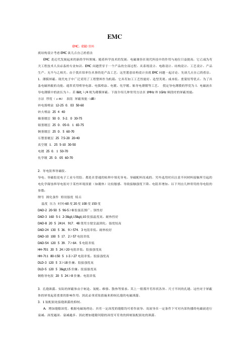
EMCEMC,ESD资料就结构设计考虑EMC谈几点自己的看法EMC是近代发展起来的新的学科领域。
随着科学技术的发展,电磁兼容在现代科技中的作用与地位日益提高,它已成为有关工程技术人员必备的专业知识。
EMC问题贯穿于一个产品的全部过程。
从系统设计,电路设计,结构设计,工艺设计,产品生产。
无不与之相关。
由于我在原单位从事的是产品工艺,这里愿意结构设计员就EMC问题一起讨论。
先谈几点自己的看法。
1.薄膜屏蔽。
现代电子中广泛采用了工程塑料作为机箱,它具有加工工艺性能好,造型美观、成本低、重量轻等优点。
为了具备电磁屏蔽的功能,通常采用喷导电漆、电弧喷涂、电镀、化学镀、贴导电薄膜等工艺。
假定导电薄膜的厚度为l,电磁波在导电薄膜中的波长为λ,若l<λ/4则为薄膜屏蔽。
下面介绍几种常用方法在1MHz和1GHz频段时的屏蔽效能:方法厚度(μm)表阻屏蔽效能(dB)锌电弧喷涂 12-25 0.03 50-60锌火喷涂 25 4 40镍基镀层 50 0.5-2.0 30-75银基镀层 25 0.05-0.1 65-75铜基镀层 25 0.5 60-70石墨基镀层 25 7.5-20 20-40真空镀 1.25 5-10 30-50电镀 25 0.1 50-70化学镀 25 0.05 60-702.导电胶和导磁胶。
导电、导磁胶是电子工业专用胶。
都是在普通的粘和中填充导电、导磁配料而成的。
另外选用时应注意不同材料接触所引起的电化学腐蚀和导电胶对于某些环境因素(如潮热)比较敏感,导致接触强度下降、电阻率增加。
以下列出几种常用的导电胶的参数:牌号固化条件剪切强度特点温度压力时间-60度20度100度150度DAD-2 20-50 5 96-5≥8胶接范围广、韧性好DAD-3 160 5-1 2-3>15>10胶接温度高、耐热性好DAD-8 20 5 2414.917.48使用方便室温固化,强度较高DAD-24 130 5 36.9≥574.3电阻率低,耐热较好DAD-10 100 5 17.2≥57电阻率低DAD-54 120 5 39.7≥64.5电阻率低HH-701 20 5 24≥20电阻率低,胶接强度高HH-711 80-150 5 1-3≥27电阻率低,胶接强度高DLD-3 120 5 3≥18价廉,胶接强度高DLD-5 120 5 3>15价廉,胶接强度高铜粉导电胶 20 5 24≥8价廉,电阻率低3.孔缝泄露。
电波吸收体

电波吸收体EMC电波暗室用/微波电波暗室用IP-BL/IP/IP-BX/ID/ICM/IB/IS/IS-SM/IK/ICT系列薄型IR/ISF/ITB系列Issue date:September 2013●记载内容,在没有予告的情况下有可能改进和变更,请予以谅解。
●RoHS指令对应产品:RoHS指令对应产品的详细内容查看这里。
http://www.tdk.co.jp/rohs/近来,随着应对电子设备的电磁环境问题的重要性越发突出,需要电波吸收材料的领域也得到极其广泛的扩大,在频带上,从兆赫带到千兆赫,直至毫米波带。
在用途方面,可适用于电子设备(通信设备、办公自动化设备、计算机、家电设备、汽车仪表设备等)的辐射噪音及抗噪音性对策,电波反射(ETC 、各种雷达等)的防止对策,EMI 对策评价设施(电波暗室等)。
TDK 为了应对这种趋势,最大限度地发挥长年积累地材料技术,电波技术,提供可满足各种用途的电波吸收材料。
电波吸收材料的应用例●电波暗室TDK电波吸收材料作为电波暗室用电波吸收材料得到了广泛应用。
照片为其中1例。
10m 法电波暗室(使用IP 作为电波吸收材料)小型电波暗室(使用ICM 作为电波吸收材料)天线评价用电波暗室(使用IS 材料和IS-SM 材料作为电波吸收材料)天线评价用电波暗室(使用IP-BX 材料作为电波吸收材料)●改善ETC 通信环境为优化电波环境而被安装在ETC (自动费用收受系统)上的ETC 用电波吸收面板例(使用ISFE27F5)●防止船舶桅杆的雷达假象照片是作为防止船舶桅杆的雷达假象用途,在主桅杆的一部分上安装TDK 电波吸收材料IR 材质的示例IS-SM050IS-060IP-100BXIP-130BXISFE27F5IR material为了有效吸收电磁能量,需要选择符合各种使用条件的最佳电波吸收材料。
TDK 电波吸收材料品种齐全,备有可适用于各种使用目的,使用条件,使用频率,必要频带等的电气,磁性损失材料。
EMC测试仪器原理分析和应用介绍

EMC测试仪器完全符合IEC61000-4-2和GB/T17626.2标准的要求,旨在为评定电气和电子设备经受静电放电时的性能制定一个共同的准则。
具有性能稳定、使用方便、根据试验要求灵活设定电压等优点,其中ESD-20的最大输出电压20Kv,ESD-30最大输出电压为30kV,方便客户选择。
主要技术参数:项目ESD-20(20kV)ESD-30(30kV)输出电压0--±20kV±5%0--±30kV±5%输出电压极性正/负正/负放电电容150pF150pF放电电阻330Ω330Ω放电电流上升时间0.7~1ns0.7~1ns工作形式单次/重复/20pps单次/重复/20pps放电次数设定1~99991~9999放电间隔0.1~9.9s0.1~9.9s放电形式接触放电/空气放电接触放电/空气放电该EMC测试仪器是按照电气、电子产品对于电快速瞬变脉冲群试验的特点和要求而专门设计的,具有可靠性好、性能稳定、使用方便等特点。
设备的指标符合IEC61000-4-4、EN60100-4-4和GB/T17626.4标准的要求。
主要技术参数项目EFT-4000EFT-4001EFT-4002输出电压0~±4500V脉冲频率2.5kHz、5kHz、100kHz±10%脉冲极性正或负内阻50Ω±20%脉冲前沿5ns±30%脉冲宽度50ns±30%脉冲串长度15ms(2.5kHz、5kHz),1ms(100kHz)脉冲串周期300ms试品耦合/去耦网络配件CDN-4020(20A)CDN-4030(30A)内置,单相三线16A内置,三相四线16A工作电源AC220V50/60Hz环境温度10-35℃重量8kg14kg15kg外形尺寸450×450×130460×520×220460×520×220EMC测试仪器——雷击浪涌发生器,雷击浪涌干扰模拟器,脉冲浪涌模拟器该EMC测试仪器用于评估设备电源线和内部连接线在经受来自开关切换及自然界雷击所引起高能量瞬变干扰时的性能提供一个共同依据。
- 1、下载文档前请自行甄别文档内容的完整性,平台不提供额外的编辑、内容补充、找答案等附加服务。
- 2、"仅部分预览"的文档,不可在线预览部分如存在完整性等问题,可反馈申请退款(可完整预览的文档不适用该条件!)。
- 3、如文档侵犯您的权益,请联系客服反馈,我们会尽快为您处理(人工客服工作时间:9:00-18:30)。
SMSC EMC1043DATASHEETRevision 1.23 (03-01-06)DatasheetPRODUCT FEATURESEMC10431°C Triple Temperature Sensor with Beta Compensation and Hotter of Two ZonesGENERAL DESCRIPTIONThe EMC1043 is a family of System Management Bus (SMBus) temperature sensors that monitors three temperature zones, one internal diode and two externally connected diodes, for PC and embedded e n v i r o n m e n ts. T h e E M C 1043 i n c l u d e s b e ta compensation circuitry to correct for variation in the beta of measurement transistors. Other extended features include resistance error correction and ideality factor configuration to eliminate major sources of temperature measurement error.1An added feature to the EMC1043 is a function that automatically compares the two external temperature zones and reports the hotter of the two temperatures.Selectable conversion rates and standby mode support low-power operation. The temperature measurement ranges support two data ranges (and formats), -64°C to +127°C and -64°C to +191°C.APPLICATIONSDesktop and Notebook Computers Hardware Management ServersEmbedded ApplicationsFEATURESSupports two External Temperature Diodes—±1°C Accuracy (40°C to 80°C)—0.125°C Resolution—Ideality Factor Configuration—Accepts 2200pF Cap Across External Diodes for Noise Suppression—Optional Resistive Error Correction on External Diode 2—Resistive Error Correction (up to 100 Ohms)—Beta CompensationInternal Temperature Diode—±3°C Accuracy (0°C to 85°C)—0.125°C ResolutionLow Power Operation—4uA Standby Current3.0V to 3.6V SupplyProgrammable Conversion Rate SMBus 2.0 Compliant—Four SMBus Address AvailableReports Hotter of Two Diodes with Dual-core CPUSIMPLIFIED BLOCK DIAGRAM1.Patents pendingEMC1043-1-ACZL-TR FOR 8 PIN, MSOP PACKAGE (ADDRESS - 1001100B) (GREEN, LEAD-FREE)EMC1043-2-ACZL-TR FOR 8 PIN, MSOP PACKAGE (ADDRESS - 1001101B) (GREEN, LEAD-FREE)EMC1043-3-ACZL-TR FOR 8 PIN, MSOP PACKAGE (ADDRESS - 1001000B) (GREEN, LEAD-FREE)EMC1043-4-ACZL-TR FOR 8 PIN, MSOP PACKAGE (ADDRESS - 1001001B) (GREEN, LEAD-FREE)EMC1043-5-ACZL-TR FOR 8 PIN, MSOP PACKAGE (ADDRESS - 1001100B) (GREEN, LEAD-FREE)BETA COMPENSATION IS DISABLED ON EXTERNAL TEMPERATURE ZONE 2 OF THE EMC1043-5Reel size is 4,000 pieces.Evaluation Boards available upon request. (EVB-EMC1043, EVB-EMC1043C)80 Arkay DriveHauppauge, NY 11788 (631) 435-6000 FAX (631) 273-3123Copyright © 2006 SMSC or its subsidiaries. All rights reserved.Circuit diagrams and other information relating to SMSC products are included as a means of illustrating typical applications. Consequently, complete information sufficient for construction purposes is not necessarily given. Although the information has been checked and is believed to be accurate, no responsibility is assumed for inaccuracies. SMSC reserves the right to make changes to specifications and product descriptions at any time without notice. Contact your local SMSC sales office to obtain the latest specifications before placing your product order. The provision of this information does not convey to the purchaser of the described semiconductor devices any licenses under any patent rights or other intellectual property rights of SMSC or others. All sales are expressly conditional on your agreement to the terms and conditions of the most recently dated version of SMSC's standard Terms of Sale Agreement dated before the date of your order (the "Terms of Sale Agreement"). The product may contain design defects or errors known as anomalies which may cause the product's functions to deviate from published specifications. Anomaly sheets are available upon request. SMSC products are not designed, intended, authorized or warranted for use in any life support or other application where product failure could cause or contribute to personal injury or severe property damage. Any and all such uses without prior written approval of an Officer of SMSC and further testing and/or modification will be fully at the risk of the customer. Copies of this document or other SMSC literature, as well as the Terms of Sale Agreement, may be obtained by visiting SMSC’s website at . SMSC is a registered trademark of Standard Microsystems Corporation (“SMSC”). Product names and company names are the trademarks of their respective holders.SMSC DISCLAIMS AND EXCLUDES ANY AND ALL WARRANTIES, INCLUDING WITHOUT LIMITATION ANY AND ALL IMPLIED WARRANTIES OF MERCHANTABILITY, FITNESS FOR A PARTICULAR PURPOSE, TITLE, AND AGAINST INFRINGEMENT AND THE LIKE,AND ANY AND ALL WARRANTIES ARISING FROM ANY COURSE OF DEALING OR USAGE OF TRADE. IN NO EVENT SHALL SMSC BE LIABLE FOR ANY DIRECT, INCIDENTAL, INDIRECT, SPECIAL, PUNITIVE, OR CONSEQUENTIAL DAMAGES; OR FOR LOST DATA,PROFITS, SAVINGS OR REVENUES OF ANY KIND; REGARDLESS OF THE FORM OF ACTION, WHETHER BASED ON CONTRACT; TORT;NEGLIGENCE OF SMSC OR OTHERS; STRICT LIABILITY; BREACH OF WARRANTY; OR OTHERWISE; WHETHER OR NOT ANY REMEDY OF BUYER IS HELD TO HAVE FAILED OF ITS ESSENTIAL PURPOSE, AND WHETHER OR NOT SMSC HAS BEEN ADVISED OF THE POSSIBILITY OF SUCH DAMAGES.1°C Triple Temperature Sensor with Beta Compensation and Hotter of Two ZonesDatasheetRevision 1.23 (03-01-06)2 SMSC EMC1043DATASHEETORDERING INFORMATION1°C Triple Temperature Sensor with Beta Compensation and Hotter of Two ZonesDatasheetSMSC EMC10433Revision 1.23 (03-01-06)DATASHEETTable of ContentsChapter 1Pin Function. . . . . . . . . . . . . . . . . . . . . . . . . . . . . . . . . . . . . . . . . . . . . . . . . . . . . . . 6Chapter 2Electrical Specifications . . . . . . . . . . . . . . . . . . . . . . . . . . . . . . . . . . . . . . . . . . . . . 72.1Absolute Maximum Ratings . . . . . . . . . . . . . . . . . . . . . . . . . . . . . . . . . . . . . . . . . . . . . . . . . . . . . . . 72.2Electrical Specifications . . . . . . . . . . . . . . . . . . . . . . . . . . . . . . . . . . . . . . . . . . . . . . . . . . . . . . . . . . 72.3System Management Bus Interface Protocol . . . . . . . . . . . . . . . . . . . . . . . . . . . . . . . . . . . . . . . . . . 92.3.1Write Byte . . . . . . . . . . . . . . . . . . . . . . . . . . . . . . . . . . . . . . . . . . . . . . . . . . . . . . . . . . . . . 92.3.2Read Byte . . . . . . . . . . . . . . . . . . . . . . . . . . . . . . . . . . . . . . . . . . . . . . . . . . . . . . . . . . . . . 92.3.3Send Byte . . . . . . . . . . . . . . . . . . . . . . . . . . . . . . . . . . . . . . . . . . . . . . . . . . . . . . . . . . . . 102.3.4Receive Byte . . . . . . . . . . . . . . . . . . . . . . . . . . . . . . . . . . . . . . . . . . . . . . . . . . . . . . . . . . 102.3.5SMBus Timing Diagram. . . . . . . . . . . . . . . . . . . . . . . . . . . . . . . . . . . . . . . . . . . . . . . . . . 102.4SMBus Addresses . . . . . . . . . . . . . . . . . . . . . . . . . . . . . . . . . . . . . . . . . . . . . . . . . . . . . . . . . . . . . 102.5SMBus Timeout . . . . . . . . . . . . . . . . . . . . . . . . . . . . . . . . . . . . . . . . . . . . . . . . . . . . . . . . . . . . . . . 10Chapter 3Product Description. . . . . . . . . . . . . . . . . . . . . . . . . . . . . . . . . . . . . . . . . . . . . . . . 113.1Power Modes . . . . . . . . . . . . . . . . . . . . . . . . . . . . . . . . . . . . . . . . . . . . . . . . . . . . . . . . . . . . . . . . . 123.2One Shot During Standby Mode. . . . . . . . . . . . . . . . . . . . . . . . . . . . . . . . . . . . . . . . . . . . . . . . . . . 123.3Operation During Run Mode. . . . . . . . . . . . . . . . . . . . . . . . . . . . . . . . . . . . . . . . . . . . . . . . . . . . . . 123.3.1Conversion Rates . . . . . . . . . . . . . . . . . . . . . . . . . . . . . . . . . . . . . . . . . . . . . . . . . . . . . . 123.3.2Dynamic Averaging . . . . . . . . . . . . . . . . . . . . . . . . . . . . . . . . . . . . . . . . . . . . . . . . . . . . . 133.4Temperature Monitors . . . . . . . . . . . . . . . . . . . . . . . . . . . . . . . . . . . . . . . . . . . . . . . . . . . . . . . . . . 133.5Temperature Measurement Results and Data . . . . . . . . . . . . . . . . . . . . . . . . . . . . . . . . . . . . . . . . 153.6Resistance Error Correction (REC) . . . . . . . . . . . . . . . . . . . . . . . . . . . . . . . . . . . . . . . . . . . . . . . . 153.7Beta Compensation . . . . . . . . . . . . . . . . . . . . . . . . . . . . . . . . . . . . . . . . . . . . . . . . . . . . . . . . . . . . 163.8Programmable Ideality Factor. . . . . . . . . . . . . . . . . . . . . . . . . . . . . . . . . . . . . . . . . . . . . . . . . . . . . 163.9Diode Faults . . . . . . . . . . . . . . . . . . . . . . . . . . . . . . . . . . . . . . . . . . . . . . . . . . . . . . . . . . . . . . . . . . 16Chapter 4Register Set and Description. . . . . . . . . . . . . . . . . . . . . . . . . . . . . . . . . . . . . . . . . 174.1Legacy Temperature Data Registers (00h, 23h, 01h, 10h, F8h, F9h) . . . . . . . . . . . . . . . . . . . . . . 194.2Extended Format Temperature Registers (FAh-FDh) . . . . . . . . . . . . . . . . . . . . . . . . . . . . . . . . . . 194.3Status Register - 02h . . . . . . . . . . . . . . . . . . . . . . . . . . . . . . . . . . . . . . . . . . . . . . . . . . . . . . . . . . . 194.4Configuration Register (03h Read, 09h Write) . . . . . . . . . . . . . . . . . . . . . . . . . . . . . . . . . . . . . . . . 204.5Configuration 2 Register - (04h). . . . . . . . . . . . . . . . . . . . . . . . . . . . . . . . . . . . . . . . . . . . . . . . . . . 214.6One Shot Register - (0Fh) . . . . . . . . . . . . . . . . . . . . . . . . . . . . . . . . . . . . . . . . . . . . . . . . . . . . . . . 214.7Ideality Configuration Registers (27h - 28h). . . . . . . . . . . . . . . . . . . . . . . . . . . . . . . . . . . . . . . . . . 224.8Beta Configuration Registers (29h - 2Ah). . . . . . . . . . . . . . . . . . . . . . . . . . . . . . . . . . . . . . . . . . . . 234.9Product ID Register (EDh) . . . . . . . . . . . . . . . . . . . . . . . . . . . . . . . . . . . . . . . . . . . . . . . . . . . . . . . 244.10Manufacturer ID Register (FEh) . . . . . . . . . . . . . . . . . . . . . . . . . . . . . . . . . . . . . . . . . . . . . . . . . . . 244.11Revision Register (FFh) . . . . . . . . . . . . . . . . . . . . . . . . . . . . . . . . . . . . . . . . . . . . . . . . . . . . . . . . . 24Chapter 5Package Outline. . . . . . . . . . . . . . . . . . . . . . . . . . . . . . . . . . . . . . . . . . . . . . . . . . . 255.1Package Markings . . . . . . . . . . . . . . . . . . . . . . . . . . . . . . . . . . . . . . . . . . . . . . . . . . . . . . . . . . . . . 261°C Triple Temperature Sensor with Beta Compensation and Hotter of Two ZonesDatasheetRevision 1.23 (03-01-06)4SMSC EMC1043DATASHEETList of FiguresFigure 1.1EMC1043 Pin Diagram . . . . . . . . . . . . . . . . . . . . . . . . . . . . . . . . . . . . . . . . . . . . . . . . . . . . . . 6Figure 2.1System Management Bus Timing Diagram . . . . . . . . . . . . . . . . . . . . . . . . . . . . . . . . . . . . . . . 9Figure 3.1EMC1043 Dual-Core System. . . . . . . . . . . . . . . . . . . . . . . . . . . . . . . . . . . . . . . . . . . . . . . . . 11Figure 3.2EMC1043-5 Mixed System . . . . . . . . . . . . . . . . . . . . . . . . . . . . . . . . . . . . . . . . . . . . . . . . . . 12Figure 3.3Block Diagram of Temperature Monitoring Circuit. . . . . . . . . . . . . . . . . . . . . . . . . . . . . . . . . 14Figure 3.4External Diode Configurations . . . . . . . . . . . . . . . . . . . . . . . . . . . . . . . . . . . . . . . . . . . . . . . . 14Figure 5.18-Pin MSOP Package Outline - 3x3mm Body 0.65mm Pitch. . . . . . . . . . . . . . . . . . . . . . . . . 251°C Triple Temperature Sensor with Beta Compensation and Hotter of Two ZonesDatasheetSMSC EMC10435Revision 1.23 (03-01-06)DATASHEETList of TablesTable 1.1EMC1043 Pin Description . . . . . . . . . . . . . . . . . . . . . . . . . . . . . . . . . . . . . . . . . . . . . . . . . . . . . 6Table 2.1Absolute Maximum Ratings. . . . . . . . . . . . . . . . . . . . . . . . . . . . . . . . . . . . . . . . . . . . . . . . . . . . 7Table 2.2Electrical Characteristics . . . . . . . . . . . . . . . . . . . . . . . . . . . . . . . . . . . . . . . . . . . . . . . . . . . . . . 7Table 2.3Write Byte Protocol . . . . . . . . . . . . . . . . . . . . . . . . . . . . . . . . . . . . . . . . . . . . . . . . . . . . . . . . . . 9Table 2.4Read Byte Protocol . . . . . . . . . . . . . . . . . . . . . . . . . . . . . . . . . . . . . . . . . . . . . . . . . . . . . . . . . . 9Table 2.5Send Byte Protocol . . . . . . . . . . . . . . . . . . . . . . . . . . . . . . . . . . . . . . . . . . . . . . . . . . . . . . . . . 10Table 2.6Receive Byte Protocol . . . . . . . . . . . . . . . . . . . . . . . . . . . . . . . . . . . . . . . . . . . . . . . . . . . . . . . 10Table 3.1Supply Current vs. Conversion Rate and ADC Averaging Factor . . . . . . . . . . . . . . . . . . . . . . 13Table 3.2EMC1043 Temperature Data Format . . . . . . . . . . . . . . . . . . . . . . . . . . . . . . . . . . . . . . . . . . . 15Table 4.1EMC1043 Register Set . . . . . . . . . . . . . . . . . . . . . . . . . . . . . . . . . . . . . . . . . . . . . . . . . . . . . . 17Table 4.2Status Register . . . . . . . . . . . . . . . . . . . . . . . . . . . . . . . . . . . . . . . . . . . . . . . . . . . . . . . . . . . . 19Table 4.3Configuration Register. . . . . . . . . . . . . . . . . . . . . . . . . . . . . . . . . . . . . . . . . . . . . . . . . . . . . . . 20Table 4.4Conversion Rate . . . . . . . . . . . . . . . . . . . . . . . . . . . . . . . . . . . . . . . . . . . . . . . . . . . . . . . . . . . 20Table 4.5Configuration 2 Register . . . . . . . . . . . . . . . . . . . . . . . . . . . . . . . . . . . . . . . . . . . . . . . . . . . . . 21Table 4.6One Shot Registers . . . . . . . . . . . . . . . . . . . . . . . . . . . . . . . . . . . . . . . . . . . . . . . . . . . . . . . . . 21Table 4.7Ideality Configuration Registers. . . . . . . . . . . . . . . . . . . . . . . . . . . . . . . . . . . . . . . . . . . . . . . . 22Table 4.8Ideality Factor Look Up Table . . . . . . . . . . . . . . . . . . . . . . . . . . . . . . . . . . . . . . . . . . . . . . . . . 22Table 4.9Beta Configuration Registers. . . . . . . . . . . . . . . . . . . . . . . . . . . . . . . . . . . . . . . . . . . . . . . . . . 23Table 4.10Beta Configuration Look Up Table. . . . . . . . . . . . . . . . . . . . . . . . . . . . . . . . . . . . . . . . . . . . . . 23Table 4.11Product ID Register . . . . . . . . . . . . . . . . . . . . . . . . . . . . . . . . . . . . . . . . . . . . . . . . . . . . . . . . . 24Table 4.12Manufacturer ID Register. . . . . . . . . . . . . . . . . . . . . . . . . . . . . . . . . . . . . . . . . . . . . . . . . . . . . 24Table 4.13Revision Register. . . . . . . . . . . . . . . . . . . . . . . . . . . . . . . . . . . . . . . . . . . . . . . . . . . . . . . . . . . 24Table 5.18-Pin MSOP Package Parameters . . . . . . . . . . . . . . . . . . . . . . . . . . . . . . . . . . . . . . . . . . . . . 251°C Triple Temperature Sensor with Beta Compensation and Hotter of Two ZonesDatasheetRevision 1.23 (03-01-06)6SMSC EMC1043DATASHEETChapter 1 Pin FunctionFigure 1.1 EMC1043 Pin Diagram Table 1.1 EMC1043 Pin DescriptionPIN PIN NO.DESCRIPTIONDP11External Diode 1 Positive (anode) Connection DN12External Diode 1 Negative (cathode) Connection DP23External Diode 2 Positive (anode) Connection DN24External Diode 2 Negative (cathode) Connection GND 5Ground VDD 6Supply VoltageSMDATA 7System Management Bus Data - bi-directional data, open drain output SMCLK8System Management Bus Clock Input1°C Triple Temperature Sensor with Beta Compensation and Hotter of Two ZonesDatasheetSMSC EMC10437Revision 1.23 (03-01-06)DATASHEETChapter 2 Electrical Specifications2.1Absolute Maximum RatingsNote:Stresses above those listed could cause damage to the device. This is a stress rating only andfunctional operation of the device at any other condition above those indicated in the operation sections of this specification is not implied. When powering this device from laboratory or system power supplies, it is important that the Absolute Maximum Ratings not be exceeded or device failure can result. Some power supplies exhibit voltage spikes on their outputs when the AC power is switched on or off. In addition, voltage transients on the AC power line may appear on the DC output. If this possibility exists, it is suggested that a clamp circuit be used.2.2 Electrical SpecificationsTable 2.1 Absolute Maximum RatingsDESCRIPTIONRATING UNIT Supply Voltage V DD-0.3 to 5.0V Voltage on SMDATA and SMCLK pins -0.3 to 5.5V Voltage on any other pin -0.3 to VDD+0.3V Operating Temperature Range -40 to 125°C Storage Temperature Range -55 to 150°CLead Temperature RangeRefer to JEDEC Spec. J-STD-020Package Thermal Characteristics for MSOP-8Thermal Resistance T JA (at 0 air flow)135.9°C/W ESD Rating, All Pins Human Body Model2000VTable 2.2 Electrical CharacteristicsV DD =3.0V to 3.6V, T A = 0°C to +85°C, Typical values at T A = 27°C unless otherwise notedPARAMETERSYMBOL MIN TYP MAX UNITS CONDITIONSDC Power Supply VoltageV DD 3.0 3.3 3.6V Average Operating CurrentI DD 340400μA 4 conversions/s See Table 4.4.I STBY24μAStandby modeInternal Temperature Monitor Temperature Accuracy ± 1± 3°C 0°C ≤T A ≤85°CTemperature Resolution0.125°C1°C Triple Temperature Sensor with Beta Compensation and Hotter of Two ZonesDatasheetRevision 1.23 (03-01-06)8SMSC EMC1043DATASHEETNote 2.1300nS rise time max is required for 400kHz bus operation. For lower clock frequencies,the maximum rise time is (0.1/F SMB )+50nSExternal Temperature Monitor Temperature AccuracyRemote Diode 40°C to 80°C Remote Diode 0°C to 125°C ± 1± 3°C °C 15°C ≤T A ≤70°C 0°C ≤T A ≤85°CTemperature Resolution 0.125°C Filter CapacitorC FILTER2.2nFConnected across external diode Note 2.2Voltage ToleranceVoltage at pin ( SMDATA,SMCLK)V TOL-0.35.5VSMBus Interface (SMDATA,SMCLK)Input High Level V IH 2.0V Input Low Level V IL 0.8V Input High/Low Current I IH /I IL-11μA Hysteresis 500mV Input Capacitance 5pF Output Low Sink Current 6mASMDATA = 0.6VSMBus Timing Clock Frequency F SMB10400kHz Spike Suppression 50ns Bus free time Start to Stop T BUF 1.3μs Hold time Start T HD:STA 0.6μs Setup time Start T SU:STA 0.6μs Setup time Stop T SU:STO 0.6μs Data Hold Time T HD:DAT 0.3μs Data Setup Time T SU:DAT 100ns Clock Low Period T LOW 1.3μs Clock High Period T HIGH 0.6μs Clock/Data Fall Time T F *300ns *Min = 20+0.1C b ns Clock/Data Rise TimeT R*300Note 2.1ns*Min = 20+0.1C b nsCapacitive Load (each bus line)C b0.6400pFTable 2.2 Electrical Characteristics (continued)V DD =3.0V to 3.6V, T A = 0°C to +85°C, Typical values at T A = 27°C unless otherwise notedPARAMETERSYMBOL MIN TYP MAX UNITS CONDITIONS1°C Triple Temperature Sensor with Beta Compensation and Hotter of Two ZonesDatasheetSMSC EMC10439Revision 1.23 (03-01-06)DATASHEETNote 2.2See SMSC Applications for Application Notes and Guidelines when measuring GPU processor diodes and CPU processor diodes.2.3 System Management Bus Interface ProtocolA host controller, such as an SMSC I/O controller, communicates with the EMC1043 via the two wire serial interface named SMBus. The SMBus interface is used to read and write registers in the EMC1043, which is a slave-only device. A detailed timing diagram is shown in Figure 2.1.Figure 2.1 System Management Bus Timing DiagramThe EMC1043 implements a subset of the SMBus specification and supports Write Byte, Read Byte,Send Byte, and Receive Byte protocols as shown. In the tables that describe the protocol, the “gray”columns indicate that the slave is driving the bus.All of the below protocols use the following convention:2.3.1Write ByteThe Write Byte is used to write one byte of data to the registers as shown in Table 2.3.2.3.2Read ByteThe Read Byte protocol is used to read one byte of data from the registers as shown in Table 2.4.DATA SENT TO DEVICE DATA SENT TO THE HOST # of bits sent# of bits sentTable 2.3 Write Byte ProtocolSTARTSLAVE ADDRESSWRACKCOMMANDACKDATAACKSTOP171181811Table 2.4 Read Byte ProtocolSTARTSLAVE ADDRESSWRACKCOMMANDACKSTARTSLAVE ADDRESSRDACKDATANACKSTOP17118117118111°C Triple Temperature Sensor with Beta Compensation and Hotter of Two ZonesDatasheetRevision 1.23 (03-01-06)10SMSC EMC1043DATASHEET2.3.3Send ByteThe Send Byte protocol is used to set the Internal Address Register to the correct Address as shown in Table 2.5. The Send Byte can be followed by the Receive Byte protocol described in Table 2.6 to read data from the register. The send byte protocol cannot be used to write data - if data is to be written to a register then the write byte protocol must be used as described in Section 2.3.1.2.3.4Receive ByteThe Receive Byte protocol is used to read data from a register when the internal register address pointer is known to be at the right location (e.g. set via Send Byte). This can be used for consecutive reads of the same register as shown in Table 2.6.2.3.5SMBus Timing DiagramThe Timing for the SMBus is shown in Figure 2.1.2.4 SMBus AddressesThe EMC1043 may be ordered with one of four slave addresses as shown in Ordering Information .Attempting to communicate with the EMC1043 SMBus interface with an invalid slave address or invalid protocol results in no response from the device and does not affect its register contents. The EMC1043supports stretching of the SMCLK signal by other devices on the SMBus but will not perform this operation itself.2.5 SMBus TimeoutThe EMC1043 includes an SMBus time-out feature. Following a 25 ms period of inactivity on the SMBus, the device will time-out and reset the SMBus interface.Table 2.5 Send Byte ProtocolSTART SLAVE ADDRWR ACK REG. ADDRACK STOP 1711811Table 2.6 Receive Byte ProtocolSTART SLAVE ADDRRD ACK REG. DATANACK STOP 17118111°C Triple Temperature Sensor with Beta Compensation and Hotter of Two ZonesDatasheetSMSC EMC104311Revision 1.23 (03-01-06)DATASHEETChapter 3 Product DescriptionThe EMC1043 is an SMBus sensor that monitors three temperature zones for use in a personal computer or embedded environment. The part may be used as a companion to one of SMSC’s broad line of SIO host devices to perform fan control and thermal management.The EMC1043-1, EMC1043-2, EMC1043-3 and EMC1043-4 are designed specifically to work with a CPU that implements the thermal diode as a PNP substrate transistor with the collector connected to GND. A new feature called beta compensation automatically compensates for measurement error caused by beta variation in CPU thermal diodes as described in Section 3.7.Because the beta compensation circuit is designed to work with PNP substrate transistors, the EMC1043-1, EMC1043-2, EMC1043-3 and EMC1043-4 are not typically used with diode-connected transistors (such as the 2N3904) or CPUs that implement the thermal diode as a two-terminal diode (such as the AMD processor). However, the beta compensation feature may be disabled by configuring the appropriate register as described in Section 4.8. For applications that measure a two-terminal thermal diode, refer to the EMC1063.A typical system is shown in Figure 3.1.The EMC1043-5 is designed to operate with a single substrate thermal diode and a discrete thermal diode such as a 2N3904. A typical system for this mixed system is shown in Figure 3.2.Figure 3.1 EMC1043 Dual-Core System1°C Triple Temperature Sensor with Beta Compensation and Hotter of Two ZonesDatasheetRevision 1.23 (03-01-06)12SMSC EMC1043DATASHEET3.1 Power ModesThe EMC1043 has two power modes.Run Mode - In this mode, the temperature monitors are active and converting at the programmed conversion rate. The average power dissipation will depend on the conversion rate. When the EMC1043 is not actively converting a channel, it goes into a lower power wait state.Standby Mode (power-up default) - in this mode, the EMC1043 is put into a low power state. In the standby mode, temperature monitoring is disabled. The device will still respond to SMBus commands.3.2 One Shot During Standby ModeThe EMC1043 supports a One-Shot command when it is in Standby Mode. Writing to the One-Shot register will cause the device to power up, perform 1 full set of temperature conversions, then return to Standby Mode.3.3 Operation During Run ModeWhen the device is active, there are two modes of operation available.Normal Mode (power-up default) - In this mode of operation, the EMC1043 continuously samples and updates all of its temperature channels.Hotter of Two Mode - In this mode, the EMC1043 continuously samples and then compares the two remote zones. The hotter of the two remote zones is loaded into the External Diode 2 Data Registers. In addition, the HOTTER bit in the Status register is set or cleared to indicate which external diode zone is hotter. If the two remote zones are exactly equal to each other, then the HOTTER bit is cleared (set to ‘0’), and the results of the two remote zones are stored in their respective registers.3.3.1Conversion RatesThe EMC1043 may be configured for different conversion rates based on the system requirements.The available rates are 1 full set of conversions per second to 16 full sets of conversions per second.The conversion rate is configured as described in Section 4.4. The available conversion rates are shown in Table 4.4.Figure 3.2 EMC1043-5 Mixed System1°C Triple Temperature Sensor with Beta Compensation and Hotter of Two ZonesDatasheetSMSC EMC104313Revision 1.23 (03-01-06)DATASHEET3.3.2Dynamic AveragingThe EMC1043 temperature channels support a new feature that measures the external diode channels for an extended time based on the selected conversion rate. This functionality can be disabled as described in Section 4.5 for increased power savings at the lower conversion rates. When Dynamic Averaging is enabled, the device will automatically adjust the sampling and measurement time for both external diode channels. This allows the device to average 2x or 4x longer than the normal 11 bit operation while still maintaining the selected conversion rate. The benefits of Dynamic Averaging are improved noise rejection due to the longer integration time as well as less random variation on the temperature measurement.The Dynamic Averaging applies when a One-Shot command is issued. The device will perform the desired averaging during the one-shot operation according to the selected conversion rate.The Dynamic Averaging will affect the average supply current based on the chosen conversion rate as shown in Table 3.1.3.4 Temperature MonitorsIn general, thermal diode temperature measurements are based on the change in forward bias voltage of a diode when operated at two different currents. This ΔV BE is then proportional to absolute temperature as shown in the following equation:Table 3.1 Supply Current vs. Conversion Rate and ADC Averaging FactorCONVERSION RATEADC AVERAGING FACTOR4X(MAX_RES = 1)(DA_n = 0)2X(MAX_RES = 0)(DA_n = 0)1X (DA_n = 1)1 / sec 160uA 120uA 100uA 2 / sec 250uA 175uA 135uA 4 / sec 440uA 275uA 200uA 8 / sec N/A 525uA 320uA 16 / secN/AN/A565uAwhere:k = Boltzmann’s constantT = absolute temperature in Kelvin [1]q = electron chargeη = diode ideality factor。
