RLS139中文资料
74hc139中文资料参数
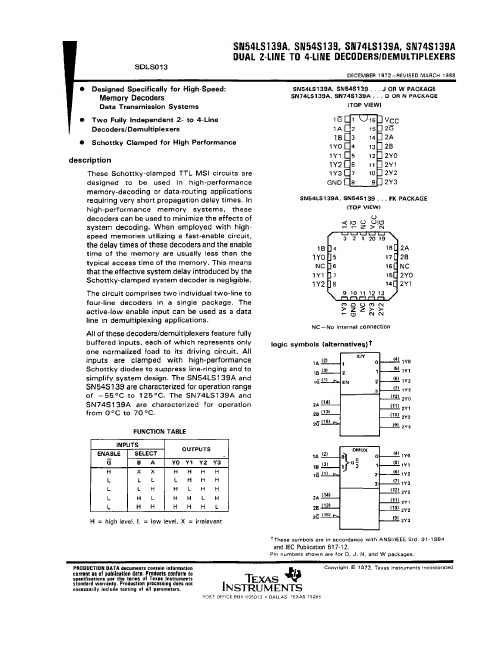
74hc139中文资料参数M74HC139/74HC139 功能:2 线—4 线译码器M74HC139/74HC139 用于高性能的存贮译码或要求传输延迟时间短的数据传输系统,在高性能存贮器系统中,用这种译码器可以提高译码系统的效率。
将快速赋能电路用于高速存贮器时,译码器的延迟时间和存贮器的赋能时间通常小于存贮器的典型存取时间,这就是说由肖特基钳位的系统译码器所引起的有效系统延迟可以忽略不计。
HC139含有两个单独的2 线—4 线译码器,当赋能输入端G为高电平时,按二进制控制输入码从4 个输出端中译出一个低电平输出。
在解调器应用中,低电平有效的赋能输入端用作数据线。
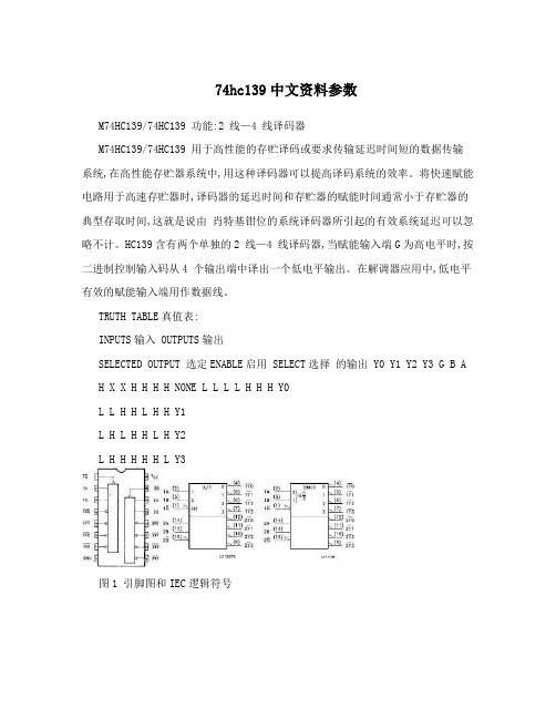
TRUTH TABLE真值表:INPUTS输入 OUTPUTS输出SELECTED OUTPUT 选定ENABLE启用 SELECT选择的输出 Y0 Y1 Y2 Y3 G B AH X X H H H H NONE L L L L H H H Y0L L H H L H H Y1L H L H H L H Y2L H H H H H L Y3图1 引脚图和IEC逻辑符号图2 输入输出等效电路图3 逻辑图引脚功能表:引脚位 SYMBOL 符号 NAME AND FUNCTION名称及功能1,15 1G,2G Enable Inputs使能输入2,3 1A,1B Address Inputs地址输入4,5,6,7 1Y0 to 1Y3 Outputs输出12,11,10,9 2Y0 to 2Y3 Outputs输出14,13 2A,2B Address Inputs地址输入8 GND Ground接地(0V)16 VCC Positive Supply Voltage正电源电压ABSOLUTE MAXIMUM RATINGS绝对最大额定值:Unit SYMBOL 符号 Parameter 参数 Value 数值单位 VCC Supply Voltage电源电压 -0.5 to +7 V VI DC Input Voltage 直流输入电压 -0.5 to VCC + 0.5 V VO DC Output Voltage直流输出电压 -0.5 to VCC + 0.5 V IIK DC Input Diode Current直流输入二极管电流 ? 20 mA IOK DC Output Diode Current直流输出二极管电流 ? 20 mA IO DC Output Current直流输出电流 ? 25 mA ICC or IGND DC VCC or Ground Current ? 50 mA PD Power Dissipation功耗 500(*) mW Tstg Storage Temperature贮藏温度 -65 to +150 ? TL Lead Temperature焊接温度 (10 sec) 300 ? RECOMMENDED OPERATING CONDITIONS建议操作条件SYMBOL Unit Parameter 参数 Value 数值符号单位 VCC Supply Voltage电源电压 2 to 6 V VI Input Voltage 输入电压 0 to VCC V VO Output Voltage 输出电压 0 to VCC V Top Operating Temperature: 操作温度:M54HC系列M74HC 系列 -55to+125 -40to +85 ?VCC = 2V 0 to 1000 tr,tf Input Rise and Fall Time输入上升和下降时间VCC = 4.5V 0 to 500 nsVCC = 6V 0 to 400 DC SPECIFICATIONS直流电气规格:Test Condition测Value 数值试条件SYMBOL Unit Parameter 参数 TA =25? 54HC and -40 to 85? -55 to 125?符号 VCC 单位 74HC 74HC 54HC(V) 最小典型最大最小最大最小最大2.0 1.5 1.5 1.5 - - - - High LevelVIH InputVoltage输入4.5 3.15 3.15 3.15 V - - - -高电平电压 6.0 4.2 4.2 4.2 - - - -2.0 0.5 0.5 0.5 - - - Low LevelVIL InputVoltage输入4.5 1.35 1.35 1.35 V - - - -低电平电压 6.0 1.8 1.8 1.8 - - - -2.0 1.9 2.0 1.9 1.9 - - -4.5 4.4 4.5 4.4 4.4 - - - High LevelVOH OutputVoltage出6.0 5.9 6.0 5.9 5.9 V - - -高电平电压 4.5 4.18 4.31 4.13 4.10 - - -6.0 5.68 5.8 5.63 5.60 - - -2.0 0.0 0.1 0.1 0.1 - - -4.5 0.0 0.1 0.1 0.1 - - - Low LevelVOL OutputVoltage输6.0 0.0 0.1 0.1 0.1 V - - -出低电平电压 4.5 0.17 0.26 0.33 0.40 - - -6.0 0.18 0.26 0.33 0.40 - - -Input LeakageII Current输入漏电6.0 VI=VCC or GND ?0.1 ?1 ?1 μA - - - -流Quiescent SupplyICC Current静态电源6.0 VI=VCC or GND 4 40 80 μA - - - -电流AC ELECTRICAL CHARACTERISTICS交流电气特性:TestConditionValue 数值测试条件 SYMBOL Unit Parameter 参数 -55 to 125? 符号单位 VCC TA =25? 54HC and 74HC - 40 to 85? 74HC 54HC(V) 最小典型最大最小最大最小最大2.0 30 75 95 110 - - - tTLH Output Transition 4.5 8 15 19 22 ns - -- tTHLTime输出过渡时间6.0 7 13 16 19 - - -2.0 45 130 165 195 - - - Propagation Delay tPLH Time 传递延迟时间4.5 15 26 33 39 ns - - - tPHL (A,B -Y) 6.0 13 22 28 33 - - -2.0 39 110 140 165 - - - Propagation Delay tPLH Time 传递延迟时间4.5 13 22 28 33 ns - - - tPHL (G -Y) 6.0 11 19 24 28 - - -Input CapacitanceCIN 5 10 10 10 pF - - - - 输入电容Power DissipationCPD (*) Capacitance功耗电46 pF - - - - - -容应用电路:图4图5 晶体管H桥电机驱动电路。
2SK1522中文资料(renesas)中文数据手册「EasyDatasheet - 矽搜」

7.如果这些产品或技术受日本出口管理限制,必须是 日本政府根据许可证出口,不能导入比批准目地以外国家.
禁止任何转移或再出口违反出口管制法律和日本及/或目地国家相关规定.
8.请与瑞萨科技公司对这些材料或产品进一步详情 其中所载.
芯片中文手册,看全文,戳
V GS = ±25 V, V DS = 0 V DS = 360 V, V GS = 0 V DS = 400 V, V GS = 0 ID =1毫安,V DS = 10 V ID = 25 A, V GS = 10 V * 1
ID = 25 A, V DS = 10 V * 1 VDS = 10 V, V GS = 0, F = 1兆赫
芯片中文手册,看全文,戳
2SK1521, 2SK1522
绝对最大额定值
(Ta = 25°C)
项目
漏极至源极电压
2SK1521
2SK1522
门源电压
漏极电流
漏电流峰值
身体流失二极管反向漏电流
频道耗散
通道温度
储存温度
注:1.PW
10 µs, 占空比
1%
2.价值在T C = 25°C
符号
ID = 25 A, V GS = 10 V, RL = 1.2
IF = 50 A, V GS = 0
IF = 50 A, V GS = 0, di F/ DT = 100 A /μs的
3
—
远期转移导纳
|yfs|
22
输入电容
Ciss —
输出电容
Coss —
反向传输电容
Crss —
导通延迟时间 上升时间 关断延迟时间 下降时间 身体向前漏二极管 电压
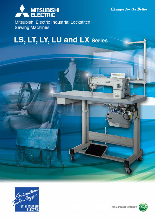
三菱电机工业缝纫机 LS, LT, LY, LU 系列 - 产品手册说明书
Various models with diverse functions and easy operation to increase productivityModels ListLT2-2220-B0B LT2-2230-B1T LT2-2250-B1TLU2-4420-B0B Industrial MaterialsLY2-3300-B0B LY2-3310-B1T LY2-3750-B1T LU2-4410-B1T-CS LU2-4400-B0B LU2-4420-B0BLU2-4400-B0B LU2-4420-B0B LU2-4430-B1T LU2-4652-B1T LU5-5720-B0TLU2-4430-B1T LU2-4652-B1T LU2-4710-B1T LU2-4730-B1T LU5-5720-B0T DY-253-00Container bagsLT2-2220-B0B LT2-2230-B1T LT2-2250-B1TJeansLY2-3310-B1T LY2-3750-B1T LY2-3319-B1T LU2-4410-B1T-CS LU2-4430-B1TLU2-4652-B1T LU5-5720-B0T LU2-4400-B0B LU2-4420-B0B LU2-4710-B1T LU2-4730-B1T Car seatsLY2-3750-B1T LU2-4410-B1T-CSLU2-4652-B1TAirbagsLT2-2230-B1T LT2-2250-B1TLT2-2220-B0BTwin-needle lockstitch:Needle feedTwin-needle lockstitch:Needle feed: Corner stitchingTwin-needle lockstitch:Needle feedShirtsSofasntroducing a new, easy-to-use twin-needle lockstitch feed cornerstitching machine capable of responding to diverse sewing needs.A new bobbin thread holding mechanism, presser mechanismupgrade, and a left-right independent adjustable thread trimmingspring have been incorporated while retaining the same beautiful,stable stitching of previous models.Sewing machine appearance has been updated with the introductionof a soft olive-white body color.The new LI MI SERVO X-G Series offers improved sewing operationease and stitching performance.Ceramic thread route withoutstanding durabilityStable thread trimmingfrom thin to thick threadsLeft-right independent adjustablethread trimming springWiper performanceenhanced(option)Magnetic type Pneumatic type* Photo shows LT2-2230/2220Menswear Womenswear WomenswearMenswearPantsBags JeansJeans PantsShirtsWomenswearMenswearJeansPantsDoubleLeader in diversified sewing work using easy to operate functions.Twin-needle lockstitch feed sewing machinesmade possible using cutting-edgetechnologies from Mitsubishi Electric.Product Speci cationsContainer bagsLY2-3310-B1TBagsCar seatsLY2-3300-B0BBagsBagsDY-253-00SofasContainer bags SofasMitsubishi Electric's popular vertical feed mechanism accurately catches hard-to-feed materials and slippery fabrics, enabling reliable stitching.The new LI MI SERVO X-G Series further improves sewing machine operation and stitching performance.Control panel has many functions for standing operation.(thread trimming type)T -shaped table legs for standing/sitting operation* Photo shows Y2-3750-B1TLY3-6840-B0TBagsLY2-3750-B1TSingle-needle lockstitch: Vertical feedSingle-needle lockstitch: Vertical feedSingle-needle lockstitch: Vertical feedSingle-needle lockstitch: Vertical feed (cylindrical high-long arm)LY2-3319-B1T Single-needle lockstitch: Vertical feed (long arm)Single-needle lockstitch: Vertical feedOperation improved with popular vertical feed mechanism and new servomotor!High-long arm contributes advanced stitching work diversity.Product Speci cationsNotes 1. The weight applies only to the sewing machine.2. Operation caution labels are attached to the sewing machine body.Lever can be mounted on the side of the control panel.●Easily separate from the panel.●Easily mount the pedal for a standing sewing machine.Variable stitch lever●Simple sequence function built-in.●nserting and removing fabrics made easy with reverse-run needle lifting function.Powerful, high-performance Limiservo X-G Series●True maintenance-free operation realized with no wear sections.* Complete energy-saving, low-noise and noise-reducing design.Reliable, popular all-digital servoThe vertical feed sandwiches and accurately feeds hard-to-feed materials.Vertical feed mechanism for accurate feedingPopular rotating left knife and fixed right knife can sharply cut thin to thick (#6) threads.(LY2-3750/LY2-3310)Stable thread trimming performance from thin to thick threads Easily adjust the stitch with the adjustment pin on the front of the arm. (LY2-3750/LY3-6840)Simple front/back stitch pitch adjustmentStitch adjustment dial with lock Automatic lubrication system eliminates the need for manual oiling. A pump feeds oil in the oil tank to the required sections, improving sewing machine durability.(LY2-3750/LY3-6840)Easy-maintenance automatic lubrication systemNeedle stop UP and DOWN positions can be adjusted separately with a single touch. The normal state can be confirmed easily via indicator lamps.(LY2-3750/LY2-3310/LY3-6840)Built-in detector for highly accurate positioning Presser foot lifter lever is on the front of the arm to improve operation ease.(LY2-3750/LY3-6840)Presser foot lifter lever with forward-facing arm* Photo shows Y2-3750-B1TQuick return with a light touch.Needle lifting and correction stitching are also possible.(LY2-3750/LY2-3310/LY3-6840)Touch back switchAirbagsLU2-4410-B1T-CSSingle-needle lockstitch: General feedLU2-4430-B1TTwin-needle lockstitch:General feedA short thread trimmer has been newly added to the car seat (CS) specifications of the general-feed machine, which is popular for stitching thick materials.Stable stitching tension, adjustable down position using the built-in detector and improved maintenance features are powerful functions that simplify operation.Sewing machine operation and stitching performance are further improved with the new LIMISERVO X-G Series.DP×17 #2336mm LU2-4400-B0BSingle-needle lockstitch: General feedBagsCar seatsSofas Container bags BagsCar seatsSofas Container bags BagsCar seatsSofasContainer bags LU2-4420-B0BTwin-needle lockstitch:General feedLU2-4730-B1TDouble-needleLU2-4710-B1T Single-needleEasy to setup*Option for LU2-4400 Series; built-in for LU2-4652 Series.Automatic presser foot lifterAccurately prevent problems like changing stitch length during sewing.Stitch adjustment dial with lockOnly a short piece of thread is left after trimming, so there’s no need to pick off threads.Short thread trimmer (LU-ST -KIT)Touch back function can be released just simply turning the button (LU2-4410/LU2-4430).Touch back switch with release functionCS specifications have been added to the car seat stitching lineup. The balance stroke and feed motion have been changed and seat stitching quality has been further improved.Car seat (CS)specifications lineup available A moving knife and fixed knife that move linearly in parallel with the feed gear are used to cut thin to thick threads (#8) with a clean cut.Stable thread trimming from thin to thick threads After the thread is trimmed, the sewing machine’s reverse run function prevents the needle from protruding from the presser foot and allows the presser foot to rise 16mm.Thick materials can be inserted and removed easily.Reverse-run needle lifting function(using LIMISERVO X)With the improved needle bar vibration mechanism, balance mechanism and upper vertical feed mechanism, machine can do up to 3,000 stitches/min even when using a double-hook. (Only LU2-4652)Double-hook and maximum stitching speed achieve 3,000 stitches/minLU2-4652-B1TStitching sampleBefore mountingAfter mounting* Option for LU2-4410 Series; standard for LU2-4652 Series.General-feed sewing machines are ideal for stitching various thick materials such as that used for car seats, bags and sofas.This high-function model incorporates a long arm while retaining presser foot interchangeability.Single-needle lockstitch: General feedBagsCar seatsSofas Container bags LU5-5720-B0TTwin-needle lockstitch:General feedProduct Speci cationsStitch typeSingle-needle lockstitch One-stitch stitching, continuous stitching continuous variable stitching, etc.Complete basting work quickly and efficiently.MenswearWomenswearMenswearWomenswearLX2-630-M1Single-needle lockstitch: BastingLX5-871-M0Single-needle lockstitch: BastingStable basting quality and improved operation ease.LX2-630-M1 FeaturesA horizontal thread trimming mechanism for basting is mounted, enabling thread tension adjustment and work efficiency to be increased.Horizontal thread trimming mechanism for bastingHorizontal hook and needle plate with needle guide prevent stitches from being skipped when using thin threadsHorizontal hook and needle plate with needle guideThe presser foot can be lifted 15.5mm (after trimming), making it easy to baste thick materials.Easy basting of thick materialsHighly efficient work is possible with continuous variable stitching, single-needle stitching and more.Highly efficient workLX5-871-M0 FeaturesStable basting quality and improved operation ease!Freely switch between one-stitch stitching and continuous stitching simply by operating the pedal. Quickly and efficiently complete basting work.Product Speci cations。
译FMVSS139轮胎测试标准
标准号139:轻型货车新子午线充气胎S1 目的和范围本标准规定了轮胎尺寸,测试要求,标签要求,定义了轮胎额定载荷S2 适用和引置条款S2.1 适用本标准适用于新子午线充气轮胎,这种轮胎主要用于1975年以后生产的车体总重不超过10000磅的轻型车辆(除摩托车和低速车辆)。
本标准不适用于特殊轮胎,特殊轮胎是指高速公路服务用的拖车轮胎,间歇高速公路上使用的农用设备轮胎,轮辋直径不超过8英寸的轮胎以及带有子午线的临时备用轮胎。
S2.2 引置条款美国试验材料学会(ASTM)F-1805-00,在冰面或者雪面直线上单轮传动牵引的标准测试方法,引置本章S3的条款。
联邦注册的的制定者对这种材料引置了美国法典(U.S.C.)第五章第552款第一条和CFR第一章第51部分。
获得ASTM F-1805-00可以登录ASTM的网站http:// /或联系ASTM,或者去信咨询宾夕法尼亚州西康舍霍肯市巴尔海港大道100号。
ASTM F-1805-00可以从国家公路交通安全管理局摘要第2055-23439款,或者国家档案局(NARA)获得。
在NARA了解这种材料的获取信息,拨打202–741–6030,或者登录:http:// /federal_register/code_of_federal_regulations/ibr_loc ations.html.S3 定义胎圈:指轮胎安装在轮辋上的部分,由钢线构成的胎圈芯和包布组成。
胎圈分裂:胎圈组件间接口的分裂。
斜交轮胎:指胎体帘布层和缓冲层相邻层帘线交叉,且与胎面中心线呈小于90℃角排列的充气轮胎。
胎体:指出去胎面胎侧和橡胶外的轮胎结构,充压后承重。
崩花:胎面和胎侧破坏掉分裂出去的碎屑。
帘线:轮胎内束成层的线。
帘线断裂:线绳与橡胶配合物间的断裂。
裂口:胎面胎壁或者橡胶密封层延伸到帘布材料出现的断面裂口。
超负荷轮胎:能承受比额定更高负荷和更高充气压力的轮胎。
凹槽:相邻两个胎面花纹间的不分。
BD139-10;BD136-16;BD139-16;BD140;BD139;中文规格书,Datasheet资料

May 2008Rev 51/9BD135 - BD136BD139 - BD140Complementary low voltage transistorFeatures■Products are pre-selected in DC current gainApplication■General purposeDescriptionThese epitaxial planar transistors are mounted in the SOT -32 plastic package. They are designed for audio amplifiers and drivers utilizingcomplementary or quasi-complementary circuits. The NPN types are the BD135 and BD139, and the complementary PNP types are the BD136 and BD140.Table 1.Device summaryOrder codes Marking Package PackagingBD135BD135SOT -32TubeBD135-16BD135-16BD136BD136BD136-16BD136-16BD139BD139BD139-10BD139-10BD139-16BD139-16BD140BD140BD140-10BD140-10BD140-16BD140-16Contents BD135 - BD136 - BD139 - BD140Contents1Electrical ratings . . . . . . . . . . . . . . . . . . . . . . . . . . . . . . . . . . . . . . . . . . . . 32Electrical characteristics . . . . . . . . . . . . . . . . . . . . . . . . . . . . . . . . . . . . . 42.1Electrical characteristics (curves) . . . . . . . . . . . . . . . . . . . . . . . . . . . . . . . 5 3Package mechanical data . . . . . . . . . . . . . . . . . . . . . . . . . . . . . . . . . . . . . 6 4Revision history . . . . . . . . . . . . . . . . . . . . . . . . . . . . . . . . . . . . . . . . . . . . 82/9BD135 - BD136 - BD139 - BD140Electrical ratings3/91 Electrical ratingsTable 2.Absolute maximum ratingsSymbolParameterValueUnitNPNPNPBD135BD139BD136BD140V CBO Collector-base voltage (I E = 0)4580-45-80V V CEO Collector-emitter voltage (I B = 0)4580-45-80V V EBO Emitter-base voltage (I C = 0)5-5V I C Collector current 1.5-1.5A I CM Collector peak current 3-3A I B Base current0.5-0.5A P TOT Total dissipation at T c ≤ 25 °C 12.5W P TOT Total dissipation at T amb ≤ 25 °C 1.25W T stg Storage temperature-65 to 150°C T jMax. operating junction temperature150°CTable 3.Thermal dataSymbolParameterMax valueUnit R thj-case Thermal resistance junction-case 10°C/W R thj-amb Thermal resistance junction-ambient100°C/WElectrical characteristics BD135 - BD136 - BD139 - BD1404/92 Electrical characteristics(T case = 25 °C unless otherwise specified)Table 4.On/off statesSymbolParameterPolarityTest conditionsValueUnitMin.Typ.Max.I CBOCollector cut-off current (I E =0)NPN V CB = 30 VV CB = 30 V , T C = 125 °C 0.110µA µA PNP V CB = -30 VV CB = -30 V , T C = 125 °C -0.1-10µA µA I EBOEmitter cut-off current (I C =0)NPN V EB = 5 V 10µA PNP V EB = -5 V -10µA V CEO(sus)(1)1.Pulsed: pulse duration = 300 µs, duty cycle 1.5%Collector-emittersustaining voltage(I B =0)NPNI C = 30 mA BD135BD1394580V V PNP I C = -30 mA BD136BD140-45-80V V V CE(sat) (1)Collector-emitter saturation voltage NPN I C = 0.5 A, I B = 0.05 A 0.5V PNP I C = -0.5 A, I B = -0.05 A -0.5V V BE (1)Base-emitter voltageNPN I C = 0.5 A, V CE = 2 V 1V PNP I C = -0.5 A, V CE = -2 V -1V h FE (1)DC current gainNPNI C = 5 mA, V CE = 2 V I C = 150 mA, V CE = 2 V I C = 0.5 A, V CE = 2 V 254025250PNPI C = -5 mA, V CE = -2 V I C = -150 mA, V CE = -2 V I C = -0.5 A, V CE = -2 V 254025250h FE (1)h FE groupsNPNI C = 150 mA, V CE = 2 V BD139-10BD135-16/BD139-1663100160250PNPI C = -150 mA, V CE = -2 V BD140-10BD136-16/BD140-1663100160250BD135 - BD136 - BD139 - BD140Electrical characteristics 2.1 Electrical characteristics (curves)Figure 2.Safe operating area Figure 3.Derating5/9Package mechanical data BD135 - BD136 - BD139 - BD140 3 Package mechanical dataIn order to meet environmental requirements, ST offers these devices in ECOPACK®packages. These packages have a lead-free second level interconnect. The category ofsecond level interconnect is marked on the package and on the inner box label, incompliance with JEDEC Standard JESD97. The maximum ratings related to solderingconditions are also marked on the inner box label. ECOPACK is an ST trademark.ECOPACK specifications are available at: 6/9BD135 - BD136 - BD139 - BD140Package mechanical data7/9Revision history BD135 - BD136 - BD139 - BD1408/94 Revision historyTable 5.Document revision historyDate RevisionChanges16-Sep-2001422-May-20085Mechanical data has been updated.BD135 - BD136 - BD139 - BD140Please Read Carefully:Information in this document is provided solely in connection with ST products. STMicroelectronics NV and its subsidiaries (“ST”) reserve the right to make changes, corrections, modifications or improvements, to this document, and the products and services described herein at any time, without notice.All ST products are sold pursuant to ST’s terms and conditions of sale.Purchasers are solely responsible for the choice, selection and use of the ST products and services described herein, and ST assumes no liability whatsoever relating to the choice, selection or use of the ST products and services described herein.No license, express or implied, by estoppel or otherwise, to any intellectual property rights is granted under this document. If any part of this document refers to any third party products or services it shall not be deemed a license grant by ST for the use of such third party products or services, or any intellectual property contained therein or considered as a warranty covering the use in any manner whatsoever of such third party products or services or any intellectual property contained therein.UNLESS OTHERWISE SET FORTH IN ST’S TERM S AND CONDITIONS OF SALE ST DISCLAIM S ANY EXPRESS OR IM PLIED WARRANTY WITH RESPECT TO THE USE AND/OR SALE OF ST PRODUCTS INCLUDING WITHOUT LIM ITATION IM PLIED WARRANTIES OF MERCHANTABILITY, FITNESS FOR A PARTICULAR PURPOSE (AND THEIR EQUIVALENTS UNDER THE LAWS OF ANY JURISDICTION), OR INFRINGEMENT OF ANY PATENT, COPYRIGHT OR OTHER INTELLECTUAL PROPERTY RIGHT. UNLESS EXPRESSLY APPROVED IN WRITING BY AN AUTHORIZED ST REPRESENTATIVE, ST PRODUCTS ARE NOT RECOMMENDED, AUTHORIZED OR WARRANTED FOR USE IN MILITARY, AIR CRAFT, SPACE, LIFE SAVING, OR LIFE SUSTAINING APPLICATIONS, NOR IN PRODUCTS OR SYSTEMS WHERE FAILURE OR MALFUNCTION MAY RESULT IN PERSONAL INJURY, DEATH, OR SEVERE PROPERTY OR ENVIRONMENTAL DAMAGE. ST PRODUCTS WHICH ARE NOT SPECIFIED AS "AUTOMOTIVE GRADE" MAY ONLY BE USED IN AUTOMOTIVE APPLICATIONS AT USER’S OWN RISK.Resale of ST products with provisions different from the statements and/or technical features set forth in this document shall immediately void any warranty granted by ST for the ST product or service described herein and shall not create or extend in any manner whatsoever, any liability of ST.ST and the ST logo are trademarks or registered trademarks of ST in various countries.Information in this document supersedes and replaces all information previously supplied.The ST logo is a registered trademark of STMicroelectronics. All other names are the property of their respective owners.© 2008 STMicroelectronics - All rights reservedSTMicroelectronics group of companiesAustralia - Belgium - Brazil - Canada - China - Czech Republic - Finland - France - Germany - Hong Kong - India - Israel - Italy - Japan - Malaysia - Malta - Morocco - Singapore - Spain - Sweden - Switzerland - United Kingdom - United States of America9/9分销商库存信息:STMBD139-10BD136-16BD139-16 BD140BD139BD135-16 BD135。
铝合金应力腐蚀开裂ASTM G139(中文翻译版)
用断裂负荷法测定热处理铝合金制品抗应力腐蚀开裂性的标准试验方法(等同采用ASTMG139-05(R2011))(中文翻译版)编制: 日期:审核: 日期:批准: 日期:修订历史修订序号对应的条号修订内容修改人批准人日期1. 目的Purpose本标准试验方法涵盖了通过断裂荷载试验方法评估抗应力腐蚀开裂(SCC)性的程序,该方法使用剩余强度作为损伤演化(在这种情况下为环境辅助开裂)的测量方法。
包括试样类型和复制、试验环境、应力水平、暴露时间、最终强度测定和原始残余强度数据的统计分析。
2. 范围Scope本标准试验方法适用于热处理铝合金,即2XXX合金和7XXX,含1.2%至3.0%铜,且试样的取向与晶粒结构相关,横向较短。
然而,用于分析数据的残余强度测量和统计数据并非针对可热处理铝合金,可用于其他试样取向和不同类型的材料。
3. 职责Responsibility程序执行:实验室授权制样人员程序监督:实验室技术负责人及相关责任人4. 原理Principle4.1本试验方法描述了使用暴露于腐蚀环境后的残余强度评估热处理铝合金产品形式(如板材、板材、挤压件、锻件和棒材)的应力腐蚀开裂敏感性的程序。
这些产品通常在板材的长横方向、板材、挤压件和锻件的短横方向以及棒材和棒材的横方向上最易发生应力腐蚀开裂。
在本试验中,根据规程G49制备的拉伸钢筋或直接拉伸板试样暴露于3.5重量%的氯化钠水溶液(规程G44)中,在其失效前移除,并进行拉伸试验,以确定已发生的腐蚀损伤量。
然后计算平均剩余强度,并使用Box-Cox变换对结果进行统计分析。
4.2该程序要求暴露无应力试样,用于排除点蚀、晶间腐蚀和一般腐蚀的影响。
这些现象会降低残余强度,但不需要施加应力。
4.3本试验方法适用于高强度铝合金(2XXX和含有7XXX的铜),通常在3.5%氯化钠中通过交替浸泡进行试验。
然而,使用剩余强度作为损伤演化度量的概念(在这种情况下,环境辅助开裂)原则上可以应用于任何合金和环境系统。
弹性联轴器的技术参数

弹性联轴器的技术参数弹性联轴器的技术参数弹性联轴器通常由金属圆棒线切割而成,常用的材质有铝合金、不锈钢、工程塑料。
弹性联轴器运用平行或螺旋切槽系统来适应各种偏差和精确传递扭矩。
弹性联轴器通常具备良好的性能而且有价格上的优势,在很多步进、伺服系统实际应用中,弹性联轴器是首选的产品。
一体成型的设计使弹性联轴器实现了零间隙地传递扭矩和无须维护的优势。
弹性联轴器主要有以下两个基本的系列:螺旋槽型和平行槽型。
凌斯LS2一体成型弹性联轴器·夹紧螺固定联轴器专业为自动化设备, 数控设备及通用机械等提供优质联轴器。
产品引进德国技术及高科技数控生产设备制做,拥有一流的技术研发团队和完善的管理体制, 并有一批优秀的售后服务人员专业为客户提供最好的传动方案, 确保设备能平稳高效运转。
例:LS2-100-0810 LS2:系列号,材料为铝合金100:外径尺寸:25.4MM ,夹紧螺丝固定 08:D1轴径为:8MM 10:D2轴径为:10MM LS2一体成型弹性联轴器特点: 1. 一体成型的2. 零回转间隙3. 弹性作用补偿径向、角向、轴向偏差4. 顺时针与逆时针回转特性完全相同5. 夹紧螺丝固定方式6. 铝合金及不锈钢材料全国统一热线:400-0769-856例:SLS2-C150-1415SLS2:系列号,材料为不锈钢C150:外径尺寸:38.1MM ,夹紧螺丝固定 14:D1轴径为:14MM 15:D2轴径为:15MM LS2特点: 1. 一体成型的金属弹性联轴器 2. 零回转间隙3. 弹性作用补偿径向、角向、轴向偏差4. 顺时针与逆时针回转特性完全相同5. 夹紧螺丝固定方式6. 铝合金及不锈钢材料凌斯LS1金属弹性联轴器·定位螺丝固定联轴器的选型指南:1. 每个系列的联轴器都有其特有的性能. 请根据使用时的具体要求, 选择合适的联轴器.2. 在选择好合适的系列产品后, 再参考相应的参数表格, 根据相应的参数确定型号.3. 确认合适的固定方式, 根据不同的需要进行选择, 合理的固定方式是设备稳定的保障, 具体请参考" 联轴器的固定方式" 部分内容. 4. 确认所选择的产品是否符合现场安装的条件. 5. 联轴器的选择要领:①容许额定扭矩-是联轴器实际使用时承受的扭矩容许值. ②容许最大扭矩-是联轴器使用时损坏的最大临界值.③容许最高转速-需要在选型时确定电机的转速在此范围内. ④容许偏心-两轴的轴心平行偏差的容许值. ⑤容许偏角-两轴之间形成的相互角度容许值. ⑥容许轴向偏差-两轴轴向移动的位移容许值.在启动, 停止, 正反转切换时, 电机会向联轴器施加大于电机最大扭矩的负载, 因此, 选择联轴器时, 应该使联轴器的额定扭矩大于电机的最大扭矩.在正反转频繁的设备中, 联轴器的额定扭矩就为电机最大扭矩的2-5倍为宜, 如果是伺服电机, 应为5-10倍为宜.LS1-17-0506MLS1:系列号,材料为铝合金17:外径尺寸:17.5MM ,定位螺丝固定 05:D1轴径为:5MM 06:D2轴径为:6MM M :螺纹式1. 一体成型的金属弹性联轴器2. 适用较小力矩的轴联接3. 零回转间隙4. 弹性作用补偿径向、角向、轴向偏差5. 定位螺丝固定凌斯LS1一体成型联轴器·定位螺丝固定是指连接两个旋转轴、传递扭矩或旋转角的机械零件。
三棱伺服电机简介资料讲解

市场情况 常用 很常用 很常用 很常用 很常用 常用 常用 常用 常用 常用
市场情况 常用 很常用 很常用 很常用 很常用 常用 常用
三菱伺服系统MR-J2S系列
MR-J2S系列的伺服配套伺服电机编码器采用了分辨 率为131072脉冲/转的绝对位置编码器,所以比MR-J2系 列私服系统具有进行更高精度控制的能力,采用高性能的 CPU,大大提高产品的响应性,速度环路频率响应提高到 550HZ。多种系列的伺服电机适应不同控制需求,伺服电 机上的编码器均支持ABS模式,只要在伺服放大器上另加 电池,就能构成绝对位置系统。三菱伺服MR-J2S系列使 用更为方便,具有优异的自动调谐性能,机械分析功能, 可以轻松实现抑制机械振动,增益搜索功能,可以自动找 出最佳增益值。该产品还有RS-232和RS-422串行通讯功 能,通过安装有伺服设置软件的个人计算机就能进行参数 设定,试运行,状态显示和增益调整等操作。
参数序号名称和功能设定值注释p00电机和控制模式选择5010hcsfe系列1kw电机位置控制模式p01选择输入滤波器0002xy0012zp02自动调谐0105选择自动调谐响应速度p03电子齿轮分子32768xy16384z电子齿轮比电机分辨率p04电子齿轮分母1963xy125zp19参数写入禁止000e所有参数均可写入p21指令脉冲选择0001正逻辑带符号脉冲串p27编码器输出脉冲10000输出脉冲伺服电机每转分辨率设定值脉冲转p54编码器输出脉冲xy1z为0000y2为0001变更伺服电机旋转方向三菱伺服参数设置表三菱伺服电机推荐型号mrj3伺服电机mrj3伺服驱动器额定转速分辨率及惯性额定扭矩最大扭矩市场情况hfkp13mrj310a3000rmin262144分辨率低惯性032nm095nm常用hfkp23mrj320a3000rmin262144分辨率低惯性064nm19nm很常用hfkp43mrj340a3000rmin262144分辨率低惯性13nm38nm很常用hfkp73mrj370a3000rmin262144分辨率低惯性24nm72nm很常用hfsp102mrj3100a2000rmin262144分辨率中惯性477nm143nm很常用hfsp152mrj3200a2000rmin262144分辨率中惯性716nm215nm常用hfsp202mrj3200a2000rmin262144分辨率中惯性955nm286nm常用hfsp352mrj3350a2000rmin262144分辨率中惯性167nm286nm常用hfsp502mrj3500a2000rmin262144分辨率中惯性239nm716nm常用hfsp702mrj3700a2000rmin262144分辨率中惯性334nm100nm常用mres伺服电机mres伺服驱动器额定转速分辨率及惯性额定扭矩最大扭矩市场情况hfkn13js100mre10akh0033000rmin131072分辨率低惯性032nm095nm常用hfkn23js100mre20akh0033000rmin131072分辨率低惯性064nm19nm很常用hfkn43js100mre40akh0033000rmin131072分辨率低惯性13nm38nm很常用hfkn73js100mre70akh0033000rmin131072分辨率低惯性24nm72nm很
12高强涤纶绳参数-概述说明以及解释
12高强涤纶绳参数-概述说明以及解释1.引言1.1 概述在撰写本文时主要讨论了12高强涤纶绳的参数相关内容。
涤纶绳作为一种常见的合成材料绳索,在现代生活中具有广泛的应用。
本文将介绍12高强涤纶绳的各项参数,包括强度、密度、耐久性、柔软性等。
首先,我们来看涤纶绳的强度参数。
12高强涤纶绳以其强大的拉力而著名,具有出色的承载能力。
其高强度使其适合应对各种复杂环境下的应力和张力要求,能够可靠地支持和固定物体。
此外,经过特殊处理的12高强涤纶绳还具有优异的防切割性能,能够有效降低切割和磨损的风险。
其次,我们需要了解涤纶绳的密度参数。
12高强涤纶绳相比于传统的绳索更加轻巧,具有较低的密度。
这一特点使得该绳绳体积小,重量轻,便于携带和使用。
同时,由于其密度相对较低,该绳具有较好的浮力,使其在水上活动中具有较强的漂浮性能,可以用于水上救援等场景。
此外,12高强涤纶绳还具有出色的耐久性。
其优质的材料和制造工艺使得该绳能够经受住长时间的使用和各种恶劣环境的考验,具有较长的使用寿命。
同时,它对紫外线、化学物质等外界环境因素具有一定的抵抗能力,减少了绳索受损的风险。
最后,我们也要关注涤纶绳的柔软性参数。
12高强涤纶绳采用柔软耐用的材料制成,具有良好的弯曲性能和抗扭转能力。
这使得绳索在使用过程中更加灵活,并且不容易打结、缠绕,提高了工作效率。
此外,12高强涤纶绳还经过特殊处理,使其表面光滑,降低了摩擦系数,减少了对周围物体的损伤。
综上所述,12高强涤纶绳具备优异的强度、密度、耐久性和柔软性参数,适用于各种领域的应用。
通过了解和掌握这些参数,我们可以更好地选择和使用涤纶绳,以满足不同场景下的需求。
1.2文章结构文章结构部分的内容如下:文章结构部分旨在介绍本文的组织结构和各部分的内容概要,使读者能够对整篇文章有一个清晰的认识和理解。
本文总共分为引言、正文和结论三个部分。
引言部分主要包括概述、文章结构和目的三个要点。
在概述中,我们将简要介绍12高强涤纶绳的背景和应用领域,以及对其参数进行详细分析的重要性。
139A收讯机说明书

139A收讯机说明书第一章概述第一节一般介绍本机系全晶体管式短波收讯机,代替139型收讯机供部队短波收讯用。
全机有三极管17只,二极管9只。
“报一宽”、“报一笨”两位供收等幅报用,“话一人工”、“话一自动”分别供收调幅报和调幅话用。
机器本体安装在面板上,与电池分别装于铝质机箱中,通过九脚插头座供电。
机箱里有一带电缆的九脚插座是作为机器从机箱中取出修理时供电用的,即所谓修理电缆。
在机箱内电源插座后上部有一安放硅胶的簧卡。
为了防护电池电液流出腐蚀电池箱、电池箱内壁喷涂有塑料(低压聚乙烯)。
机器附带有帆布袋、耳机、软天线、工具和维护件等。
本机行进间背负收听重量约3.5公斤(包括机器、电池、耳机、天线及背带),体积约278×102×192毫米。
本机能在一40℃至+45℃的环境温度范围内正常工作和连续工作。
第二节性能概要1、频率范围:1.5~18兆赫,划分为三个波段:1波段:1.5~3.6兆赫2波段:3.6~8.5兆赫3波段:8.5~18兆赫2、灵敏度:收报时不劣于7微伏(讯号噪声比,宽报为10:1,窄报为10:1)。
收话时不劣于14微伏(讯号噪声比为10:1)。
3、选择性:2倍输入带宽2.2~4.4千赫。
100倍输入带宽不大于8千赫。
4、象频抗拒比:1波段大于100倍2波段大于80倍3波段大于25倍5、中频抗拒比:大于10000倍6、中频频率:465±2千赫7、电源消耗:在额定电压(10.5伏)下,静态(无讯号)总电流,话位不大于25毫安,报位不大于30毫安。
最大输出时总电流不大于50毫安。
8、晶体管:高频放大器(级联线路)8AG27 2只混频器8AG27 1只本机振荡器8AG27 1只中频放大器3AG22 4只拍频振荡器3AG22 1只2CW3 1只检波器2AP3 1.只自动增益控制检波器2AP3 1只自动增益控制放大器8AG22 1只低频放大器3AX22(3AX21)5只稳压电源3AX22(3AX21)2只2CW14 1只强讯号保护2CP45 4只低放温度补偿3AB1.A 1只9、电源:本机电源由7节1号干电池串联组成,正端接地,额定工作电压是10.5伏。
UL13中文版
附图:
图 7.1-整体性电缆 图 35.1-抗张试验设备 图 35.2-抗张试验夹具 图 36.1-柔韧性试验之塔轮
4
ቤተ መጻሕፍቲ ባይዱ绍
1 范围
1.1 此标准适用于 60-250℃单芯或多芯功率限制电路电缆,为建筑物内部固定配线(有些也标 记为直埋),主要用于 NEC Article725 及其它适用条款描述的 Class2 和 Class 3 电路。这些要求 覆盖的电缆为:
23.1 概述… … … … … … … … … … … … … … … … … … … … … … … … … … … … … … … … … 22 23.2 UL 测试… … … … … … … … … … … … … … … … … … … … … … … … … … … … … … … ...22 23.3 FT4/IEEE 1202 试验… … … … … … … … … … … … … … … … … … … … … … … … … ..… 22 24 耐日光试验… … … … … … … … … … … … … … … … … … … … … … … … … … … … … ..… … … .22 25 (供选择的)Class2 电缆火花和介电强度试验… … … … … … … … … … … … … … … ..… … 23 26 Class3 和 PLTC 电缆绝缘后的火花试验… … … … … … … … … … … … … … … … … … … … ..23 27 Class3 和 PLTC 电缆介质耐电压测试… … … … … … … … … … … … … … … … … … … … ..… 23 27A 长期水中绝缘电阻试验… … … … … … … … … … … … … … … … … … … … … … … … … ..… ..25 28 60.0℉(15.6℃)时绝缘电阻… … … … … … … … … … … … … … … … … … ..… … … … … … .25 29 确定倍乘系数(用于调整绝缘电阻)试验程序… … … … … … … … … … … … … … … … … .26
SN54LS139A中文资料
PACKAGING INFORMATIONOrderable Device Status(1)PackageType PackageDrawingPins PackageQtyEco Plan(2)Lead/Ball Finish MSL Peak Temp(3)76007012A ACTIVE LCCC FK201TBD Call TI Level-NC-NC-NC 7600701EA ACTIVE CDIP J161TBD Call TI Level-NC-NC-NC 7600701EA ACTIVE CDIP J161TBD Call TI Level-NC-NC-NC 7600701FA ACTIVE CFP W161TBD Call TI Level-NC-NC-NC 7600701FA ACTIVE CFP W161TBD Call TI Level-NC-NC-NC 7700401EA ACTIVE CDIP J161TBD Call TI Level-NC-NC-NC 7700401EA ACTIVE CDIP J161TBD Call TI Level-NC-NC-NC 7700401FA ACTIVE CFP W161TBD Call TI Level-NC-NC-NC 7700401FA ACTIVE CFP W161TBD Call TI Level-NC-NC-NCJM38510/30702B2A ACTIVE LCCC FK201TBD Call TI Level-NC-NC-NCJM38510/30702B2A ACTIVE LCCC FK201TBD Call TI Level-NC-NC-NCJM38510/30702BEA ACTIVE CDIP J161TBD Call TI Level-NC-NC-NCJM38510/30702BEA ACTIVE CDIP J161TBD Call TI Level-NC-NC-NCJM38510/30702BFA ACTIVE CFP W161TBD Call TI Level-NC-NC-NCJM38510/30702BFA ACTIVE CFP W161TBD Call TI Level-NC-NC-NCJM38510/30702SEA ACTIVE CDIP J161TBD Call TI Level-NC-NC-NCJM38510/30702SEA ACTIVE CDIP J161TBD Call TI Level-NC-NC-NCJM38510/30702SFA ACTIVE CFP W161TBD Call TI Level-NC-NC-NCJM38510/30702SFA ACTIVE CFP W161TBD Call TI Level-NC-NC-NC SN54LS139AJ ACTIVE CDIP J161TBD Call TI Level-NC-NC-NC SN54LS139AJ ACTIVE CDIP J161TBD Call TI Level-NC-NC-NC SN54S139J ACTIVE CDIP J161TBD Call TI Level-NC-NC-NC SN54S139J ACTIVE CDIP J161TBD Call TI Level-NC-NC-NC SN74LS139AD ACTIVE SOIC D1640Green(RoHS&no Sb/Br)CU NIPDAU Level-1-260C-UNLIMSN74LS139AD ACTIVE SOIC D1640Green(RoHS&no Sb/Br)CU NIPDAU Level-1-260C-UNLIMSN74LS139ADE4ACTIVE SOIC D1640Green(RoHS&no Sb/Br)CU NIPDAU Level-1-260C-UNLIMSN74LS139ADE4ACTIVE SOIC D1640Green(RoHS&no Sb/Br)CU NIPDAU Level-1-260C-UNLIMSN74LS139ADR ACTIVE SOIC D162500Green(RoHS&no Sb/Br)CU NIPDAU Level-1-260C-UNLIMSN74LS139ADR ACTIVE SOIC D162500Green(RoHS&no Sb/Br)CU NIPDAU Level-1-260C-UNLIMSN74LS139ADRE4ACTIVE SOIC D162500Green(RoHS&no Sb/Br)CU NIPDAU Level-1-260C-UNLIMSN74LS139ADRE4ACTIVE SOIC D162500Green(RoHS&no Sb/Br)CU NIPDAU Level-1-260C-UNLIMSN74LS139AN ACTIVE PDIP N1625Pb-Free(RoHS)CU NIPDAU Level-NC-NC-NCSN74LS139AN ACTIVE PDIP N1625Pb-Free(RoHS)CU NIPDAU Level-NC-NC-NC SN74LS139AN3OBSOLETE PDIP N16TBD Call TI Call TISN74LS139AN3OBSOLETE PDIP N16TBD Call TI Call TIOrderable Device Status(1)PackageType PackageDrawingPins PackageQtyEco Plan(2)Lead/Ball Finish MSL Peak Temp(3)SN74LS139ANE4ACTIVE PDIP N1625Pb-Free(RoHS)CU NIPDAU Level-NC-NC-NCSN74LS139ANE4ACTIVE PDIP N1625Pb-Free(RoHS)CU NIPDAU Level-NC-NC-NCSN74LS139ANSR ACTIVE SO NS162000Green(RoHS&no Sb/Br)CU NIPDAU Level-1-260C-UNLIMSN74LS139ANSR ACTIVE SO NS162000Green(RoHS&no Sb/Br)CU NIPDAU Level-1-260C-UNLIMSN74LS139ANSRE4ACTIVE SO NS162000Green(RoHS&no Sb/Br)CU NIPDAU Level-1-260C-UNLIMSN74LS139ANSRE4ACTIVE SO NS162000Green(RoHS&no Sb/Br)CU NIPDAU Level-1-260C-UNLIMSN74S139AD ACTIVE SOIC D1640Green(RoHS&no Sb/Br)CU NIPDAU Level-1-260C-UNLIMSN74S139ADE4ACTIVE SOIC D1640Green(RoHS&no Sb/Br)CU NIPDAU Level-1-260C-UNLIMSN74S139AN ACTIVE PDIP N1625Pb-Free(RoHS)CU NIPDAU Level-NC-NC-NC SN74S139AN3OBSOLETE PDIP N16TBD Call TI Call TISN74S139ANE4ACTIVE PDIP N1625Pb-Free(RoHS)CU NIPDAU Level-NC-NC-NCSN74S139ANSR ACTIVE SO NS162000Green(RoHS&no Sb/Br)CU NIPDAU Level-1-260C-UNLIMSN74S139ANSRE4ACTIVE SO NS162000Green(RoHS&no Sb/Br)CU NIPDAU Level-1-260C-UNLIM SNJ54LS139AFK ACTIVE LCCC FK201TBD Call TI Level-NC-NC-NC SNJ54LS139AFK ACTIVE LCCC FK201TBD Call TI Level-NC-NC-NC SNJ54LS139AJ ACTIVE CDIP J161TBD Call TI Level-NC-NC-NC SNJ54LS139AJ ACTIVE CDIP J161TBD Call TI Level-NC-NC-NC SNJ54LS139AW ACTIVE CFP W161TBD Call TI Level-NC-NC-NC SNJ54LS139AW ACTIVE CFP W161TBD Call TI Level-NC-NC-NC SNJ54S139FK ACTIVE LCCC FK201TBD Call TI Level-NC-NC-NC SNJ54S139FK ACTIVE LCCC FK201TBD Call TI Level-NC-NC-NC SNJ54S139J ACTIVE CDIP J161TBD Call TI Level-NC-NC-NC SNJ54S139J ACTIVE CDIP J161TBD Call TI Level-NC-NC-NC SNJ54S139W ACTIVE CFP W161TBD Call TI Level-NC-NC-NC SNJ54S139W ACTIVE CFP W161TBD Call TI Level-NC-NC-NC (1)The marketing status values are defined as follows:ACTIVE:Product device recommended for new designs.LIFEBUY:TI has announced that the device will be discontinued,and a lifetime-buy period is in effect.NRND:Not recommended for new designs.Device is in production to support existing customers,but TI does not recommend using this part in a new design.PREVIEW:Device has been announced but is not in production.Samples may or may not be available.OBSOLETE:TI has discontinued the production of the device.(2)Eco Plan-The planned eco-friendly classification:Pb-Free(RoHS)or Green(RoHS&no Sb/Br)-please check /productcontent for the latest availability information and additional product content details.TBD:The Pb-Free/Green conversion plan has not been defined.Pb-Free(RoHS):TI's terms"Lead-Free"or"Pb-Free"mean semiconductor products that are compatible with the current RoHS requirements for all6substances,including the requirement that lead not exceed0.1%by weight in homogeneous materials.Where designed to be solderedat high temperatures,TI Pb-Free products are suitable for use in specified lead-free processes.Green(RoHS&no Sb/Br):TI defines"Green"to mean Pb-Free(RoHS compatible),and free of Bromine(Br)and Antimony(Sb)based flame retardants(Br or Sb do not exceed0.1%by weight in homogeneous material)(3)MSL,Peak Temp.--The Moisture Sensitivity Level rating according to the JEDEC industry standard classifications,and peak solder temperature.Important Information and Disclaimer:The information provided on this page represents TI's knowledge and belief as of the date that it is provided.TI bases its knowledge and belief on information provided by third parties,and makes no representation or warranty as to the accuracy of such information.Efforts are underway to better integrate information from third parties.TI has taken and continues to take reasonable steps to provide representative and accurate information but may not have conducted destructive testing or chemical analysis on incoming materials and chemicals.TI and TI suppliers consider certain information to be proprietary,and thus CAS numbers and other limited information may not be available for release.In no event shall TI's liability arising out of such information exceed the total purchase price of the TI part(s)at issue in this document sold by TI to Customer on an annual basis.IMPORTANT NOTICETexas Instruments Incorporated and its subsidiaries (TI) reserve the right to make corrections, modifications, enhancements, improvements, and other changes to its products and services at any time and to discontinue any product or service without notice. Customers should obtain the latest relevant information before placing orders and should verify that such information is current and complete. All products are sold subject to TI’s terms and conditions of sale supplied at the time of order acknowledgment.TI warrants performance of its hardware products to the specifications applicable at the time of sale in accordance with TI’s standard warranty. T esting and other quality control techniques are used to the extent TI deems necessary to support this warranty. Except where mandated by government requirements, testing of all parameters of each product is not necessarily performed.TI assumes no liability for applications assistance or customer product design. Customers are responsible for their products and applications using TI components. T o minimize the risks associated with customer products and applications, customers should provide adequate design and operating safeguards.TI does not warrant or represent that any license, either express or implied, is granted under any TI patent right, copyright, mask work right, or other TI intellectual property right relating to any combination, machine, or process in which TI products or services are used. Information published by TI regarding third-party products or services does not constitute a license from TI to use such products or services or a warranty or endorsement thereof. Use of such information may require a license from a third party under the patents or other intellectual property of the third party, or a license from TI under the patents or other intellectual property of TI.Reproduction of information in TI data books or data sheets is permissible only if reproduction is without alteration and is accompanied by all associated warranties, conditions, limitations, and notices. Reproduction of this information with alteration is an unfair and deceptive business practice. TI is not responsible or liable for such altered documentation.Resale of TI products or services with statements different from or beyond the parameters stated by TI for that product or service voids all express and any implied warranties for the associated TI product or service and is an unfair and deceptive business practice. TI is not responsible or liable for any such statements. Following are URLs where you can obtain information on other Texas Instruments products and application solutions:Products ApplicationsAmplifiers Audio /audioData Converters Automotive /automotiveDSP Broadband /broadbandInterface Digital Control /digitalcontrolLogic Military /militaryPower Mgmt Optical Networking /opticalnetwork Microcontrollers Security /securityTelephony /telephonyVideo & Imaging /videoWireless /wirelessMailing Address:Texas InstrumentsPost Office Box 655303 Dallas, Texas 75265Copyright 2005, Texas Instruments Incorporated。
SN74ALS139N,SN74ALS139DRE4,SN74ALS139DRG4,SN74ALS139NSR,SN74ALS139NSRE4, 规格书,Datasheet 资料
Addendum-Page 1PACKAGING INFORMATIONOrderable Device Status(1)Package Type PackageDrawingPins Package QtyEco Plan(2)Lead/Ball Finish MSL Peak Temp (3)Samples (Requires Login)5962-87683012A ACTIVE LCCC FK 201TBD Call TI Call TI 5962-8768301EA ACTIVE CDIP J 161TBD Call TI Call TI 5962-8768301FA ACTIVE CFP W 161TBD Call TI Call TISN54ALS139J ACTIVE CDIP J 161TBDA42N / A for Pkg TypeSN74ALS139D ACTIVE SOIC D 1640Green (RoHS & no Sb/Br)CU NIPDAU Level-1-260C-UNLIM SN74ALS139DE4ACTIVE SOIC D 1640Green (RoHS & no Sb/Br)CU NIPDAU Level-1-260C-UNLIM SN74ALS139DG4ACTIVE SOIC D 1640Green (RoHS & no Sb/Br)CU NIPDAU Level-1-260C-UNLIM SN74ALS139DR ACTIVE SOIC D 162500Green (RoHS & no Sb/Br)CU NIPDAU Level-1-260C-UNLIM SN74ALS139DRE4ACTIVE SOIC D 162500Green (RoHS & no Sb/Br)CU NIPDAU Level-1-260C-UNLIM SN74ALS139DRG4ACTIVE SOIC D 162500Green (RoHS & no Sb/Br)CU NIPDAU Level-1-260C-UNLIM SN74ALS139N ACTIVE PDIP N 1625Pb-Free (RoHS)CU NIPDAU N / A for Pkg Type SN74ALS139N3OBSOLETE PDIP N 16TBD Call TICall TISN74ALS139NE4ACTIVE PDIP N 1625Pb-Free (RoHS)CU NIPDAU N / A for Pkg Type SN74ALS139NSR ACTIVE SO NS 162000Green (RoHS & no Sb/Br)CU NIPDAU Level-1-260C-UNLIM SN74ALS139NSRE4ACTIVE SO NS 162000Green (RoHS & no Sb/Br)CU NIPDAU Level-1-260C-UNLIM SN74ALS139NSRG4ACTIVE SO NS 162000Green (RoHS & no Sb/Br)CU NIPDAU Level-1-260C-UNLIM SNJ54ALS139FK ACTIVE LCCC FK 201TBD POST-PLATE N / A for Pkg TypeSNJ54ALS139J ACTIVE CDIP J 161TBD A42N / A for Pkg Type SNJ54ALS139WACTIVECFPW161TBDA42N / A for Pkg Type(1)The marketing status values are defined as follows:ACTIVE: Product device recommended for new designs.LIFEBUY: TI has announced that the device will be discontinued, and a lifetime-buy period is in effect.NRND: Not recommended for new designs. Device is in production to support existing customers, but TI does not recommend using this part in a new design.芯天下--/PREVIEW: Device has been announced but is not in production. Samples may or may not be available.OBSOLETE: TI has discontinued the production of the device.(2) Eco Plan - The planned eco-friendly classification: Pb-Free (RoHS), Pb-Free (RoHS Exempt), or Green (RoHS & no Sb/Br) - please check /productcontent for the latest availability information and additional product content details.TBD: The Pb-Free/Green conversion plan has not been defined.Pb-Free (RoHS): TI's terms "Lead-Free" or "Pb-Free" mean semiconductor products that are compatible with the current RoHS requirements for all 6 substances, including the requirement that lead not exceed 0.1% by weight in homogeneous materials. Where designed to be soldered at high temperatures, TI Pb-Free products are suitable for use in specified lead-free processes.Pb-Free (RoHS Exempt): This component has a RoHS exemption for either 1) lead-based flip-chip solder bumps used between the die and package, or 2) lead-based die adhesive used between the die and leadframe. The component is otherwise considered Pb-Free (RoHS compatible) as defined above.Green (RoHS & no Sb/Br): TI defines "Green" to mean Pb-Free (RoHS compatible), and free of Bromine (Br) and Antimony (Sb) based flame retardants (Br or Sb do not exceed 0.1% by weight in homogeneous material)(3) MSL, Peak Temp. -- The Moisture Sensitivity Level rating according to the JEDEC industry standard classifications, and peak solder temperature.Important Information and Disclaimer:The information provided on this page represents TI's knowledge and belief as of the date that it is provided. TI bases its knowledge and belief on information provided by third parties, and makes no representation or warranty as to the accuracy of such information. Efforts are underway to better integrate information from third parties. TI has taken and continues to take reasonable steps to provide representative and accurate information but may not have conducted destructive testing or chemical analysis on incoming materials and chemicals. TI and TI suppliers consider certain information to be proprietary, and thus CAS numbers and other limited information may not be available for release.In no event shall TI's liability arising out of such information exceed the total purchase price of the TI part(s) at issue in this document sold by TI to Customer on an annual basis.OTHER QUALIFIED VERSIONS OF SN54ALS139, SN74ALS139 :•Catalog: SN74ALS139•Military: SN54ALS139NOTE: Qualified Version Definitions:•Catalog - TI's standard catalog product•Military - QML certified for Military and Defense ApplicationsAddendum-Page 2芯天下--/TAPE AND REEL INFORMATION*All dimensions are nominalDevicePackage Type Package Drawing Pins SPQReel Diameter (mm)Reel Width W1(mm)A0(mm)B0(mm)K0(mm)P1(mm)W (mm)Pin1Quadrant SN74ALS139DR SOIC D 162500330.016.4 6.510.3 2.18.016.0Q1SN74ALS139NSRSONS162000330.016.48.210.52.512.016.0Q1*All dimensions are nominalDevice Package Type Package Drawing Pins SPQ Length(mm)Width(mm)Height(mm) SN74ALS139DR SOIC D162500333.2345.928.6SN74ALS139NSR SO NS162000367.0367.038.0IMPORTANT NOTICETexas Instruments Incorporated and its subsidiaries(TI)reserve the right to make corrections,enhancements,improvements and other changes to its semiconductor products and services per JESD46C and to discontinue any product or service per JESD48B.Buyers should obtain the latest relevant information before placing orders and should verify that such information is current and complete.All semiconductor products(also referred to herein as“components”)are sold subject to TI’s terms and conditions of sale supplied at the time of order acknowledgment.TI warrants performance of its components to the specifications applicable at the time of sale,in accordance with the warranty in TI’s terms and conditions of sale of semiconductor products.Testing and other quality control techniques are used to the extent TI deems necessary to support this warranty.Except where mandated by applicable law,testing of all parameters of each component is not necessarily performed.TI assumes no liability for applications assistance or the design of Buyers’products.Buyers are responsible for their products and applications using TI components.To minimize the risks associated with Buyers’products and applications,Buyers should provide adequate design and operating safeguards.TI does not warrant or represent that any license,either express or implied,is granted under any patent right,copyright,mask work right,or other intellectual property right relating to any combination,machine,or process in which TI components or services are rmation published by TI regarding third-party products or services does not constitute a license to use such products or services or a warranty or endorsement e of such information may require a license from a third party under the patents or other intellectual property of the third party,or a license from TI under the patents or other intellectual property of TI.Reproduction of significant portions of TI information in TI data books or data sheets is permissible only if reproduction is without alteration and is accompanied by all associated warranties,conditions,limitations,and notices.TI is not responsible or liable for such altered rmation of third parties may be subject to additional restrictions.Resale of TI components or services with statements different from or beyond the parameters stated by TI for that component or service voids all express and any implied warranties for the associated TI component or service and is an unfair and deceptive business practice. TI is not responsible or liable for any such statements.Buyer acknowledges and agrees that it is solely responsible for compliance with all legal,regulatory and safety-related requirements concerning its products,and any use of TI components in its applications,notwithstanding any applications-related information or support that may be provided by TI.Buyer represents and agrees that it has all the necessary expertise to create and implement safeguards which anticipate dangerous consequences of failures,monitor failures and their consequences,lessen the likelihood of failures that might cause harm and take appropriate remedial actions.Buyer will fully indemnify TI and its representatives against any damages arising out of the use of any TI components in safety-critical applications.In some cases,TI components may be promoted specifically to facilitate safety-related applications.With such components,TI’s goal is to help enable customers to design and create their own end-product solutions that meet applicable functional safety standards and requirements.Nonetheless,such components are subject to these terms.No TI components are authorized for use in FDA Class III(or similar life-critical medical equipment)unless authorized officers of the parties have executed a special agreement specifically governing such use.Only those TI components which TI has specifically designated as military grade or“enhanced plastic”are designed and intended for use in military/aerospace applications or environments.Buyer acknowledges and agrees that any military or aerospace use of TI components which have not been so designated is solely at the Buyer's risk,and that Buyer is solely responsible for compliance with all legal and regulatory requirements in connection with such use.TI has specifically designated certain components which meet ISO/TS16949requirements,mainly for automotive ponents which have not been so designated are neither designed nor intended for automotive use;and TI will not be responsible for any failure of such components to meet such requirements.Products ApplicationsAudio /audio Automotive and Transportation /automotiveAmplifiers Communications and Telecom /communicationsData Converters Computers and Peripherals /computersDLP®Products Consumer Electronics /consumer-appsDSP Energy and Lighting /energyClocks and Timers /clocks Industrial /industrialInterface Medical /medicalLogic Security /securityPower Mgmt Space,Avionics and Defense /space-avionics-defense Microcontrollers Video and Imaging /videoRFID OMAP Mobile Processors /omap TI E2E Community Wireless Connectivity /wirelessconnectivityMailing Address:Texas Instruments,Post Office Box655303,Dallas,Texas75265Copyright©2012,Texas Instruments Incorporated。
MODEL139资料

1 5/16" (33.3 mm) Industrial Single TurnCermet Bushing Mount ModelModel 139Vishay Spectrol For technical questions, contact: sfer@Document Number: 5703814Revision: 28-May-07Not for New DesignThis Model 139 is only for maintenance purposes. It is not recommended for new designs and will be obsolete in a near future.FEATURES•Very high ohmic values available: up to 2 M Ω•Center tap available•Continuous rotation and mechanical stops both standard •High power ratingELECTRICAL SPECIFICATIONSPARAMETERSTANDARD SPECIAL Ohmic Value 500 Ω to 2 M Ω500 Ω to 2 M ΩTolerance± 20 %± 5 %Linearity (Independent)STANDARD BEST PRACTICAL± 0.5 %± 0.25 %Output Smoothness 0.1 % maximum Power Rating40 °C ambient5 Wderated to zero at 125 °C Electrical Rotation Continuous 345° ± 4°Stops340° ± 5°Insulation Resistance 1000 M Ω minimum at 500 V DCDielectric Strength1000 V RMS , 60 Hz Absolute Minimum Resistance 1.0 % of total resistanceMinimum Voltage0.5 % maximum Temperature Coefficient of Resistance± 100 ppm/°C maximumMATERIAL SPECIFICATIONSHousing Molded glass filled thermoplastic Rear Lid Glass filled thermoset plastic Shaft Stainless steel, non-magnetic TerminalsBrass, plated for solderability,Non-passivatedMount HardwareLockwasher Internal Tooth: Panel Nut:Steel, nickel plated Brass, nickel platedENVIRONMENTAL SPECIFICATIONSVibration 15 Gs thru 2000 HzShock 50 g Salt Spray 48 h Rotational Life 2 million Shaft RevolutionsOperating Temperature Range- 55 °C to + 125 °CORDERING INFORMATION/DESCRIPTION139B 020KBO10MODELBUSHING MOUNTMECHANICAL OPTIONS OTHER OPTIONALFEATURES RESISTANCE CODEPACKAGING 0. Continuous 2. Stops0. Standard (end taps)1. Center tap (within 5° of electrical center)Box of 10 piecesOther characteristics will be standard as described on this specification sheet. If special characteristics are required such as special linearity tolerance, special resistance tolerance, non-linear functions, etc., please state these on your order.SAP PART NUMBERING GUIDELINES139B 21103B10MODELSTYLEMECHANICAL OPTIONS FEATURES OHMIC VALUEPACKAGING With stopsWith center tapBox of 10 pieces元器件交易网Model 1391 5/16" (33.3 mm) Industrial Single T urnCermet Bushing Mount ModelVishay SpectrolDocument Number: 57038For technical questions, contact: sfer@Revision: 28-May-0715Not for New DesignDIMENSIONSin inches (millimeters)MECHANICAL SPECIFICATIONSPARAMETER Rotation 360° (continuous) 340° ± 5° stopsBearing TypeSleeveT orque (Maximums)STARTING1.0 oz. - in (72 g - cm)RUNNING0.7 oz. - in (50.40 g - cm)Runouts (Maximums)Shaft Runout (TIR)0.002" (0.05 mm)Pilot Dia. Runout (TIR)0.003" (0.08 mm)Lateral Runout (TIR)0.005" (0.13 mm)Shaft End Play 0.008" (0.20 mm)Shaft Radial Play 0.003" (0.08 mm)Weight 1.0 oz. maximum (28.35 g)Stop Strength8.0 in - lbs (9.21 kg - cm) (stops version only)POWER RATING CHARTMARKINGUnitIdentificationUnits shall be marked with Vishay Spectrol name, model number, resistance andtolerance, linearity, terminal identification, and data code Applicable test procedures: MIL-R-39023元器件交易网Document Number: 91000Revision: 18-Jul-081DisclaimerLegal Disclaimer NoticeVishayAll product specifications and data are subject to change without notice.Vishay Intertechnology, Inc., its affiliates, agents, and employees, and all persons acting on its or their behalf (collectively, “Vishay”), disclaim any and all liability for any errors, inaccuracies or incompleteness contained herein or in any other disclosure relating to any product.Vishay disclaims any and all liability arising out of the use or application of any product described herein or of any information provided herein to the maximum extent permitted by law. The product specifications do not expand or otherwise modify Vishay’s terms and conditions of purchase, including but not limited to the warranty expressed therein, which apply to these products.No license, express or implied, by estoppel or otherwise, to any intellectual property rights is granted by this document or by any conduct of Vishay.The products shown herein are not designed for use in medical, life-saving, or life-sustaining applications unless otherwise expressly indicated. Customers using or selling Vishay products not expressly indicated for use in such applications do so entirely at their own risk and agree to fully indemnify Vishay for any damages arising or resulting from such use or sale. Please contact authorized Vishay personnel to obtain written terms and conditions regarding products designed for such applications.Product names and markings noted herein may be trademarks of their respective owners.元器件交易网。
139-型电子管接收机简介与维修图纸
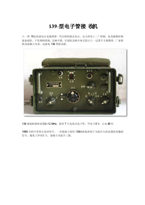
139-型电子管接收机
八一型15瓦短波电台是我国第一代自研的制式电台,由天津电工二厂研制,抗美援朝时期装备部队,下发到师团级,反响不错。
后部队反映合体式的大八一过重不方便携带,厂家将收讯部独立出来,这就是139型收讯机。
139接收机频率范围2~12 MHz,使用7只直热式电子管,甲电1.5 V,乙电90 V。
1969年的中苏珍宝岛冲突中,一名新战士使用139接收机抄到了失踪许久的巡逻队的微弱信号,避免了冲突扩大,战场立功连升三级。
电子管139的后续型号是使用了锗晶体管的139A和锗管硅管混合的139B,体积、重量、功耗大幅度降低,但效果都没有电子管139号。
由于电子管在抗核爆方面独到的性能,电子管139并未立刻退出历史舞台,作为战备物资一直生产到70电台末。
- 1、下载文档前请自行甄别文档内容的完整性,平台不提供额外的编辑、内容补充、找答案等附加服务。
- 2、"仅部分预览"的文档,不可在线预览部分如存在完整性等问题,可反馈申请退款(可完整预览的文档不适用该条件!)。
- 3、如文档侵犯您的权益,请联系客服反馈,我们会尽快为您处理(人工客服工作时间:9:00-18:30)。
25˚C −25˚C
5
10
15
20
25
30
REVERSE VOLTAGE : VR (V)
REVERSE VOLTAGE : VR (V)
Fig. 1 Forward characteristics
Fig. 2 Reverse characteristics
Fig. 3 Capacitance between terminals characteristics
200Байду номын сангаас
100
6 f=1MHz 5 4 3 2 1 0 0
50 20 10 5 2 1
125˚C 75˚C
20 10 5 2 1 0.5 0.2 0.1 0 5 10 15 20 25 30 35 40
Ta=25˚C 50˚C 75˚C
0.5 0.2 0
0.2 0.4 0.6 0.8 1.0 1.2 1.4 1.6 1.8 FORWARD VOLTAGE : VF (V)
100
10
SURGE CURRENT : Isurge (A)
REVERSE RECOVERY TIME : trr (ns)
VR=6V Ta=25˚C Irr=1/10IR 75
PULSE 8 Single pulse
6
50
4
25
2
0 0
5
10
15
20
25
30
0 0.1m
FORWARD CURRENT : IF (mA)
Parameter
Peak reverse voltage DC reverse voltage Peak forward current Mean rectifying current Surge current (1ms) Power dissipation Junction temperature Storage temperature
1m 10m 100m 1 PULSE WIDTH : Tw (ms)
10
Fig. 4 Reverse recovery time characteristics
Fig.5 Surge current characteristics
0.01µF
D.U.T.
5kΩ PULSE GENERATOR OUTPUT 50Ω 50Ω SAMPLING OSCILLOSCOPE
CATHODE BAND 0.4 0.4
φ1.4±0.1
3.4
+0.2 −0.1
φ1.5Max.
!Construction Silicon epitaxial planar
ROHM : LLDS JEDEC : LL-34 Common : mini-MELF
!Absolute maximum ratings (Ta=25°C)
元器件交易网
RLS139
Diodes
!Electrical characteristics curves (Ta=25°C)
100
FORWARD CURRENT : IF (mA)
50
REVERSE CURRENT : IR (nA)
100˚C
CAPACITANCE BETWEEN TERMINALS : CT (pF)
!Electrical characteristics (Ta=25°C)
Parameter Forward voltage Reverse current Capacitance between terminals Reverse recovery time Symbol VF IR CT trr Min. Typ. 1.0 0.45 2 30 Max. 1.2 20 5 50 Unit V nA pF ns IF=100mA VR=30V VR=0.5V, f=1MHz VR=6V, IF =10mA, RL =50Ω Conditions
Fig. 6 Reverse recovery time (trr) measurement circuit
元器件交易网
RLS139
Diodes
Low-leakage Switching Diode
RLS139
!Applications High speed switching !External dimensions (Units : mm)
!Features 1) High reliability. 2) Small surface areas mounting type. (LLDS (LL-34) ) 3) The typical reverse current is extrermely low of 0.45nA.
Symbol VRM VR IFM IO Isurge P Tj Tstg
Limits 90 80 400 130 600 300 175 −65~+175
Unit V V mA mA mA mW ˚C ˚C
!Cathode band colors
Type RLS139 1st Color Band 2nd Color Band Gray Gray
