P2S接口通信协议说明书
标准modbus协议文本样本

标准modbus协议文本样本标准s modbus协议文本本文档所提供的信息仅供参考之用,不能作为科学依据,请勿模仿。
文档如有不当之处,请联系本人或网站删除。
ISCS与与子接口协议版本:V南京南瑞集团公司修订记录版本日期起草审阅交叉审阅备注V1.0-07-27陆艮峰初稿本文档所提供的信息仅供参考之用,不能作为科学依据,请勿模仿。
文档如有不当之处,请联系本人或网站删除。
1通信接口基于以太网的P MODBUS TCP/IP协议S ISCS系统的P FEP(前端处理器)配置为主机,子系统的通讯设备配置为从机。
S ISCS系统每s500ms向子系统发送一次轮询报文。
2MODBUS TCP/IP协议协议概述P MODBUSTCP/IP协议在应用层采用S MODBUS信息定义,在传输层和网络层采用用TCP/IP,用于以太网通讯。
P MODBUSTCP/IP协议和I OSI各层之间的对应关系由下图表示::(::参考OSI模型的应用层模型)1199世纪070年代S MODBUS协议初次发布,至今已经在工业自动化领域广泛应用。
S MODBUS协议获取简便(),且便于实现。
S MODBUS协议本身没有变化,但对报文的发送方式和速率作了改变,以满足工业应用的实时性需求。
P MODBUS/TCP由此产生。
MODBUS TCPP/IP就是简单地将S MDOBUS帧嵌入到P TCP帧中。
P TCP/IP的请求//应答机制能和S MODBUS本身的主//从机制很好的配合工作。
本文档所提供的信息仅供参考之用,不能作为科学依据,请勿模仿。
文档如有不当之处,请联系本人或网站删除。
报文格式组成(标准MODBUSTCP/IP)报文格式组成::报头功能码数据报头描述::字段客户端服务端事务标识由客户端初始化服务端从接收到的请求中拷贝协议标识由客户端初始化服务端从接收到的请求中拷贝长度由客户端初始化服务端初始化((应答))单元标识由客户端初始化服务端从接收到的请求中拷贝事务标识::用于事务配对。
中国移动通信信息资源站实体与互联网短消息网关接口协议
中国移动通信信息资源站实体与互联网短消息网关接口协议(V1.2)中国移动通信集团公司2001/6/121.编制说明本规范为中国移动通信集团公司企业规范,规定信息资源站实体与互联网短消息网关的应用层接口协议。
本协议版本为1.2版。
2.缩略语ISMG Internet Short Message Gateway 互联网短消息网关SMPP Short Message Peer to Peer 短消息点对点协议CMPP China Mobile Peer to Peer 中国移动点对点协议TLS Transport Layer Security 传输层安全SMC Short Message Center 短消息中心3.网络结构因特网SC业务中心即ISMG记录了全网的SMC的位置,要求SP的功能实体向ISMG 发CMPP_SUBMIT消息,由ISMG将消息转发到某SMC上。
同时,SMC也可向ISMG发送短消息,由ISMG发送给相应的SP。
维护管理中心对ISMG进行管理。
4.CMPP功能概述CMPP用以建立短消息中心和SP之间的通路,业务和信息的提供由SP完成。
可以为实现移动数据增值业务提供服务,例如以下业务:Email通知、语音信箱通知、Internet发短消息、移动台发Email、催费通知、自动综合业务信息台(信息点播业务,主要有:天气预报、股票信息、航班信息等)。
以下以Email通知业务为例,讲述信息的流程:◆某因特网的用户向SP的Email Server发送一封Email,◆SP的POP3 SERVER激活过滤进程,如果该用户申请了Email通知业务,则过滤进程将用户登记的手机号码取出,将Email的标题取出,绑定在CMPP_SUBMIT消息中,发送给ISMG,◆ISMG将检查CMPP_SUBMIT消息中“接收业务的手机号码”字段,则在ISMG中查询该手机用户归属的SMC的地址,然后发送给SMC。
◆ISMG得到确认消息后,将消息转换成CMPP_SUBMIT_REP,发回给SP。
中国联通短消息接口协议
中国联合通信公司短消息网关系统接口协议(SGIP)版本1.2中国联合通信公司二零零一年十月目录1概述 (1)1.1协议说明 (1)1.2适用范围 (1)1.3参考资料 (1)1.4术语表 (1)2系统体系结构 (3)2.1消息从本地SMSC到本地SP (4)2.2消息从本地SP到本地SMSC (4)2.3消息从本地SMSC到异地SP (4)2.4消息从本地SP到异地SMSC (4)2.5路由选择 (4)3通信流程 (6)3.1专用SGIP方式 (6)3.2通用HTTP方式 (6)3.3通信节点编号规则 (7)3.4序列号的定义 (7)3.5通信的安全性 (8)3.6用户鉴权 (8)3.6.1被叫方付费 (8)3.6.2SP付费 (8)3.6.3第三方付费 (8)3.7SP与SMG的通信 (9)3.7.1通用HTTP方式 (9)3.7.1.1从SP到SMG的命令 (10)3.7.1.2从SMG到SP的命令 (10)3.7.2专用SGIP方式 (10)3.7.2.1通信初始化 (10)3.7.2.2通信过程 (11)3.7.2.3通信结束 (12)3.7.2.4故障处理 (12)3.7.2.5从SP到SMG的消息 (13)3.7.2.6从SMG到SP的消息 (13)3.8SMG与SMG之间的通信 (14)3.8.1通信初始化 (14)3.8.2通信过程 (14)3.8.3通信结束 (15)3.8.4故障处理 (15)3.8.5两个SMG之间的消息 (15)3.9SMG与GNS之间的通信 (15)3.9.1通信初始化 (15)3.9.2通信过程 (16)3.9.3通信结束 (16)3.9.4故障处理 (16)3.9.5从SMG到GNS的消息 (16)3.9.6从GNS到SMG的消息 (17)4消息定义 (18)4.1基于通用HTTP的消息定义 (18)4.1.1Submit操作 (18)4.1.1.1Submit命令的请求内容 (18)4.1.1.2Submit命令的应答内容 (19)4.1.2Deliver操作 (20)4.1.2.1Deliver命令的请求内容 (20)4.1.2.2Deliver命令的应答内容 (20)4.1.3Report操作 (21)4.1.3.1Report命令的请求内容 (21)4.1.3.2Report命令的应答内容 (21)4.1.4UserRpt操作 (22)4.1.4.1UserRpt命令的请求内容 (22)4.1.4.2UserRpt命令的应答内容 (22)4.1.5Trace操作 (22)4.1.5.1Trace命令的请求内容 (22)4.1.5.2Trace命令的应答内容 (23)4.2基于专用SGIP的消息定义 (23)4.2.1数据类型 (23)4.2.2消息头的格式 (24)4.2.3消息体的格式 (24)4.2.3.1Bind操作 (24)4.2.3.2Unbind操作 (25)4.2.3.3Submit操作 (25)4.2.3.4Deliver操作 (28)4.2.3.5Report操作 (29)4.2.3.6AddSP操作 (29)4.2.3.7ModifySP操作 (30)4.2.3.8DeleteSP操作 (31)4.2.3.9QueryRoute操作 (31)4.2.3.10AddTeleSeg操作 (32)4.2.3.11ModifyTeleSeg操作 (33)4.2.3.12DeleteTeleSeg操作 (34)4.2.3.13AddSMG操作 (34)4.2.3.14ModifySMG操作 (35)4.2.3.15DeleteSMG操作 (35)4.3鉴权消息定义 (36)4.3.1CheckUser命令的语法 (36)4.3.2CheckUser_Resp应答的语法 (36)4.3.3UserRpt命令的语法 (36)4.3.4UserRpt_Resp应答的语法 (36)4.4测试消息定义 (37)4.4.1Trace命令的语法 (37)4.4.2Trace_Resp应答的语法 (37)5常量定义 (38)5.1消息ID定义 (38)5.2错误码定义 (38)5.3计费类别定义 (39)5.4R EPORT 状态与短消息状态的映射 (39)附录1: 全网路由表的格式示范 (40)附录2: 本地路由表的格式示范 (41)附录3: HTTP承载方式示范 (42)1概述1.1协议说明本协议是SMG和SP之间、SMG和GNS之间、以及SMG和SMG之间的接口协议,简称SGIP。
中国移动互联网短信网关接口协议

中国移动通信集团公司研发中心 第 2 页 共 42 页
中国移动通信互联短信网关接口协议
7.6.4 ISMG 向汇接网关查询 MO 路由(CMPP_MO_ROUTE)操作 ................... 27 7.6.5 ISMG 向汇接网关获取 MT 路由(CMPP_GET_MT_ROUTE)操作 ........... 29 7.6.6 ISMG 向汇接网关获取 MO 路由(CMPP_GET_MO_ROUTE)操作 .......... 30 7.6.7 ISMG 向汇接网关更新 MT 路由(CMPP_MT_ROUTE_UPDATE)操作..... 31 7.6.8 ISMG 向汇接网关更新 MO 路由(CMPP_MO_ROUTE_UPDATE)操作 .... 32 7.6.9 汇接网关向 ISMG 更新 MT 路由(CMPP_PUSH_MT_ROUTE_UPDATE)操 作 .................................................................................................................... 34 7.6.10 汇接网关向 ISMG 更新 MO 路由(CMPP_PUSH_MO_ROUTE_UPDATE) 操作................................................................................................................. 34 7.7 系统定义 .......................................................................................................... 36 7.7.1 Command_Id 定义..................................................................................... 36 附录 1 MO 状态报告的产生.......................................................................................................................... 39 修订历史................................................................................................................................................................. 41
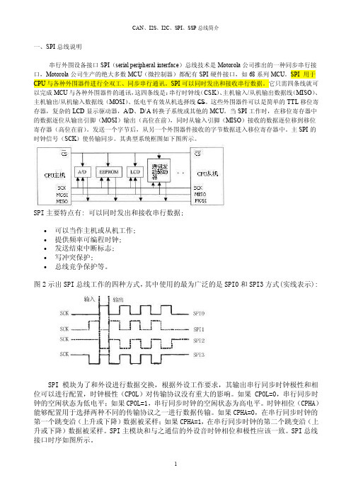
can、i2s、i2c、spi、ssp总线简介【优质】
一、SPI总线说明串行外围设备接口SPI(serial peripheral interface)总线技术是Motorola公司推出的一种同步串行接口,Motorola公司生产的绝大多数MCU(微控制器)都配有SPI硬件接口,如68系列MCU。
SPI 用于CPU与各种外围器件进行全双工、同步串行通讯。
SPI可以同时发出和接收串行数据。
它只需四条线就可以完成MCU与各种外围器件的通讯,这四条线是:串行时钟线(CSK)、主机输入/从机输出数据线(MISO)、主机输出/从机输入数据线(MOSI)、低电平有效从机选择线CS。
这些外围器件可以是简单的TTL移位寄存器,复杂的LCD显示驱动器,A/D、D/A转换子系统或其他的MCU。
当SPI工作时,在移位寄存器中的数据逐位从输出引脚(MOSI)输出(高位在前),同时从输入引脚(MISO)接收的数据逐位移到移位寄存器(高位在前)。
发送一个字节后,从另一个外围器件接收的字节数据进入移位寄存器中。
主SPI的时钟信号(SCK)使传输同步。
其典型系统框图如下图所示。
SPI主要特点有: 可以同时发出和接收串行数据;∙可以当作主机或从机工作;∙提供频率可编程时钟;∙发送结束中断标志;∙写冲突保护;∙总线竞争保护等。
图2示出SPI总线工作的四种方式,其中使用的最为广泛的是SPI0和SPI3方式(实线表示):SPI 模块为了和外设进行数据交换,根据外设工作要求,其输出串行同步时钟极性和相位可以进行配置,时钟极性(CPOL)对传输协议没有重大的影响。
如果 CPOL=0,串行同步时钟的空闲状态为低电平;如果CPOL=1,串行同步时钟的空闲状态为高电平。
时钟相位(CPHA)能够配置用于选择两种不同的传输协议之一进行数据传输。
如果CPHA=0,在串行同步时钟的第一个跳变沿(上升或下降)数据被采样;如果CPHA=1,在串行同步时钟的第二个跳变沿(上升或下降)数据被采样。
SPI主模块和与之通信的外设音时钟相位和极性应该一致。
(MODBUS接入)PECSTAR 2 第三章要点
第三章标准MODBUS规约通讯接入说明MODBUS规约是MODICON公司为其设备所定义的一种规约格式。
由于该规约简单、实用,因而被国外大多数厂商所支持,目前国内一些厂商的设备也支持该种规约。
同循环式远动规约一样,PecStar 2也提供了对标准MODBUS规约的支持。
对于具有MODBUS规约的主站(MASTER)系统,PecStar 2系统可以作为MODBUS的从站(SLA VE);对于具有MODBUS规约的从站(SLA VE)系统或设备,PecStar 2系统可以作为MODBUS 的主站(MASTER),从而实现数据的传输。
本章将从PecStar 2的主站端和从站端两方面接入进行介绍。
3.1 MODBUS规约主站端接入3.1.1 标准接入方法这里所指标准接入方法,是指凡是那些具有标准MODBUS从站规约的仪表或系统,如无特殊要求,都可以采用这种标准方法直接接入到PecStar 2中来。
这是MODBUS规约主站端的通用接入方法。
3.1.1.1 驱动程序的功能1.前台实时数据(模拟量AI、开关量DI)采集。
2.实现数字量遥控。
3.实现模拟量遥调。
4.由上位机产生的开关量(DI)变位报警。
同一子站下,可串接多种支持MODBUS规约的不同类型设备。
由于不同的设备可能采用了不同的MODBUS地址段,每种设备可能都有自己独特的数据格式,因此,系统将根据针对设备的配置文件(用文本方式编写),来区分不同的MODBUS设备。
PecStar 2安装时,附送一些常见设备的MODBUS配置表,此配置文件可理解为MODBUS的地址映射表,如3720ACM、7300ION。
如果你需要接入的设备不在此范围内,你可根据下一节提供的说明自行编写配置文件,即可接入该类设备。
配置文件的编写请参考本章的“3.1.1.5 MODBUS主站配置文件”。
MODBUS地址表文件主要包含以下内容:(1)有效的MODBUS寄存器段地址。
(2)指定数据段内的模拟量、开关量在PecStar 2中对应的测点序号规则。
某某通信公司技术规范外部接口分册

•数据源接口:是省级经营分析系统从外部系统获取数据的接口
•互动接口:是省级经营分析系统为外部系统提供数据信息的接口
•功能接口:主要包括省级经营分析系统与4A安全平台接口、信
息推送接口
目录 1、总体说明 2、数据源接口 3、互动接口 4、功能接口
接口数据来源
一级业务支撑系统
一级VGOP系统
无线音乐、手机视频、 12580、手机报、飞 信、DM、PIM、139邮 箱、手机支付、手机阅 读、手机游戏、 PushMail
新业务营销
一级经营分析系统
体验、行业 应用终端
中央业务平台
DM平台
12580平台
PIM平台
手机视频平台
无线音乐平台 手机报平台
飞信平台
139邮箱平台
手机支付平台 手机游戏平台
手机阅读平台 PushMail平台
业务支撑网接口域 省级业务支撑系统
省级经营分析系统 省级VGOP系统
省级CRM系统
ETL
省级BOSS系统
原手机电视接口停止,变更为手机新增的手机视频接口。 ✓ 依据:原手机电视接口内容,就是现在的手机视频接口内 容,因此跟进一级VGOP给经分的手机视频接口进行增补。
92财务类接口单元
本次规范新增财务类接口。具体包括:广告成本、宣传成本、 通信网运营成本、营销机构成本、销售费用、管理费用六个 接口。
94网络信令接口单元
蓝色空心箭头表示 数据源接口
粉色空心箭头表示 互动接口
潜蓝色空心双向箭 头表示功能类接口
实心黑色箭头表示省级 经营分析内部数据流
直接从省级业务支撑系统获取相关数据,如省级NG1-BOSS、 NG1-CRM;
直接从省级外部数据源系统,如:网管系统、彩铃平台、 DSMP平台、OTA平台、WAP网关、网络信令采集子系统、 VGOP平台、ERP/MIS系统等获取相关数据;
2接口协议解析及应用

PS/2接口协议解析及应用什么是PS/2接口PS/2接口是指用于连接计算机主机和键盘、鼠标等输入设备的一种串行接口。
它是IBM公司在PC机上广泛应用的一种标准接口。
PS/2接口在传输数据时采用的是异步传输方式,可单向传输数据,且不支持热插拔。
PS/2接口协议的工作原理PS/2接口的引脚及功能PS/2接口有6个引脚,其中4个是数据传输相关的,2个是电源供应相关的。
数据传输相关的引脚如下:•数据线(Data):用于传输数据,是双向传输的•时钟线(Clock):用于传输时钟信号,是一个单向输入的引脚•接收端中断线(RXRDY):用于告诉主机有数据传入,是一个单向输出的引脚•发送端中断线(TXRDY):用于告诉输入设备有数据需要传输,是一个单向输出的引脚电源供应相关的引脚如下:•电源线(+5V):提供电源供应,一般是从主机那获取电源•地线(GND):接地引脚,提供接地功能PS/2接口协议的传输流程PS/2接口协议传输流程包括初始化、应答、数据传输和结束四个步骤。
初始化当输入设备被插入时,它会等待主机发送初始化命令。
主机会发送两个字节的初始化命令,使输入设备开始接收时钟信号,并开始在数据线上传输数据。
应答输入设备在接收到初始化命令后,会发送一个应答信号,表示它已准备好接收数据。
应答信号是一个Low的电平脉冲,时长为100us。
数据传输主机成功发送初始化命令并收到输入设备的应答信号后,就可以开始进行数据传输。
主机通过时钟线发送时钟信号,每次只传输一个字节的数据。
每传输一位时,都会等待输入设备的响应。
输入设备响应有两种情况:•正确响应:在时钟信号的上升沿,输入设备将数据线置为High 或Low,表示数据的二进制位。
•错误响应:在时钟信号的上升沿,输入设备不响应,主机必须重新传输上一个数据位。
当主机完成一个字节的传输后,输入设备会发送一个校验位,用于检验数据传输的正确性。
结束数据传输结束后,主机和输入设备都会发送结束信号。
AXICOM P2信号转发器说明书
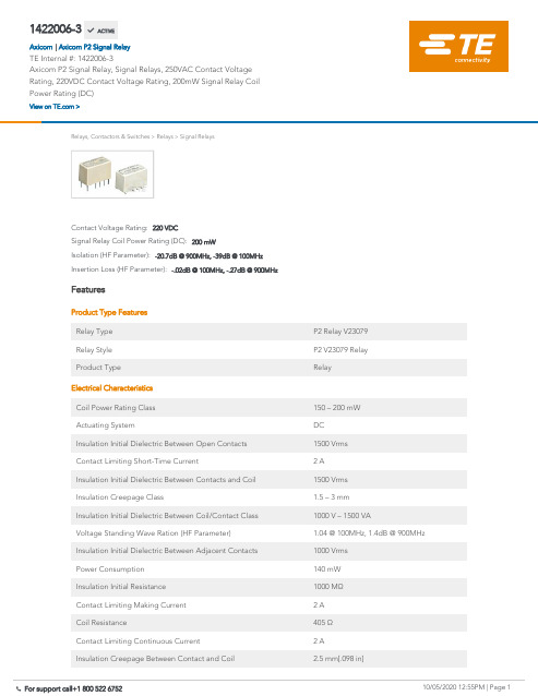
1422006-3Axicom P2 Signal Relay, Signal Relays, 250VAC Contact Voltage Rating, 220VDCContact Voltage Rating, 200mW Signal Relay Coil Power Rating (DC)Relays, Contactors & Switches>Relays>Signal RelaysInsertion Loss (HF Parameter):-.02dB @ 100MHz, -.27dB @ 900MHzIsolation (HF Parameter):-20.7dB @ 900MHz, -39dB @ 100MHzSignal Relay Coil Power Rating (DC):200 mWContact Voltage Rating:220 VDCFeaturesProduct Type FeaturesRelay Type P2 Relay V23079Relay Style P2 V23079 RelayProduct Type RelayElectrical CharacteristicsCoil Power Rating Class150 – 200 mWActuating System DCInsulation Initial Dielectric Between Open Contacts1500 VrmsContact Limiting Short-Time Current 2 AInsulation Initial Dielectric Between Contacts and Coil1500 VrmsInsulation Creepage Class 1.5 – 3 mmInsulation Initial Dielectric Between Coil/Contact Class1000 V – 1500 VAVoltage Standing Wave Ration (HF Parameter) 1.04 @ 100MHz, 1.4dB @ 900MHzInsulation Initial Dielectric Between Adjacent Contacts1000 VrmsPower Consumption140 mWInsulation Initial Resistance1000 MΩContact Limiting Making Current 2 ACoil Resistance405 ΩContact Limiting Continuous Current 2 AInsulation Creepage Between Contact and Coil 2.5 mm[.098 in]1422006-3 ACTIVEAxicomTE Internal #:1422006-3Axicom P2 Signal Relay, Signal Relays, 250VAC Contact VoltageRating, 220VDC Contact Voltage Rating, 200mW Signal Relay CoilPower Rating (DC)View on >Axicom P2 Signal Relay|Coil Type MonostableContact Limiting Breaking Current 2 AContact Switching Load (Min)10mA @ .2VCoil Special Features Overmolded CoilContact Voltage Rating220 VDCSignal Relay Coil Power Rating (DC)200 mWSignal Relay Coil Voltage Rating9 VACSignal Relay Contact Switching Voltage (Max)220 VDCSignal Relay Coil Magnetic System Monostable, DC, PolarizedSignal CharacteristicsIsolation (HF Parameter)-20.7dB @ 900MHz, -39dB @ 100MHz Insertion Loss (HF Parameter)-.02dB @ 100MHz, -.27dB @ 900MHz Body FeaturesWeight 2.8 g[.0988 oz]Contact FeaturesContact Plating Material GoldContact Current Class0 – 2 AContact Special Features Bifurcated/Twin ContactsSignal Relay Contact Current Rating 2 ASignal Relay Contact Arrangement 2 Form C (CO)Contact Material AgNiContact Number of Poles2Termination FeaturesTermination Type Surface MountMechanical AttachmentSignal Relay Mounting Type Printed Circuit BoardDimensionsWidth Class (Mechanical) 6 – 8 mmWidth7.2 mm[.283 in]Height9.9 mm[.39 in]Length Class (Mechanical)14 – 16 mmInsulation Clearance Between Contact and Coil 1.3 mm[.051 in]Height Class (Mechanical)9 – 10 mmLength14.6 mm[.575 in]Insulation Clearance Class0 – 2.5 mmUsage ConditionsEnvironmental Ambient Temperature (Max)85 °C[85 °F]Environmental Ambient Temperature Class70 – 85°CEnvironmental Category of Protection RTIIIOperating Temperature Range-40 – 85 °C, -40 – 85 °COperation/ApplicationPerformance Type High DielectricPackaging FeaturesPackaging Method ReelProduct ComplianceFor compliance documentation, visit the product page on >EU RoHS Directive 2011/65/EU CompliantEU ELV Directive 2000/53/EC CompliantChina RoHS 2 Directive MIIT Order No 32, 2016No Restricted Materials Above ThresholdEU REACH Regulation (EC) No. 1907/2006Current ECHA Candidate List: JUN 2020(209)Candidate List Declared Against: JUL 2019(201)Does not contain REACH SVHCHalogen Content Not Low Halogen - contains Br or Cl > 900ppm.Solder Process Capability Reflow solder capable to 245°CProduct Compliance DisclaimerThis information is provided based on reasonable inquiry of our suppliers and represents our current actual knowledgebased on the information they provided. This information is subject to change. The part numbers that TE has identified asEU RoHS compliant have a maximum concentration of 0.1% by weight in homogenous materials for lead, hexavalentchromium, mercury, PBB, PBDE, DBP, BBP, DEHP, DIBP, and 0.01% for cadmium, or qualify for an exemption to theselimits as defined in the Annexes of Directive 2011/65/EU (RoHS2). Finished electrical and electronic equipment productswill be CE marked as required by Directive 2011/65/EU. Components may not be CE marked. Additionally, the partnumbers that TE has identified as EU ELV compliant have a maximum concentration of 0.1% by weight in homogenousmaterials for lead, hexavalent chromium, and mercury, and 0.01% for cadmium, or qualify for an exemption to these limitsas defined in the Annexes of Directive 2000/53/EC (ELV). Regarding the REACH Regulation, the information TE provideson SVHC in articles for this part number is based on the latest European Chemicals Agency (ECHA) ‘Guidance onrequirements for substances in articles’ posted at this URL: https://echa.europa.eu/guidance-documents/guidance-on-reachTE Model / Part #6318384-5HIGH PIN COUNT HEADERTE Model / Part #4-292229-0MINI COMMON TERMINATION HEADERSTE Model / Part #1-1879745-4RP 1J 750R 0.1% 15PPM CUT LENGTHTE Model / Part #6-103635-718 MTE HDR SRRA LTCH.100CL LFTE Model / Part #1-1586041-818P VAL-U-LOK R/A HDR V2TE Model / Part #5650462-4ASSY,RECEPTACLE,EUROCARD,TYPETE Model / Part #535091-5048 EURO TYPE C RECEPT ST ASSYTE Model / Part #2176049-5Thick Film Resistor: Current SenseSignal Relays(92)TE Model / Part #CAT-AX41-P1AXICOM P2 HIGH DIELECTRICCompatible PartsAlso in the Series Axicom P2 Signal RelayCustomers Also BoughtTE Model / Part #3-1624246-4RSS3 470R 5% AMMO PKTE Model / Part #1571625-1TACT,6X6,SMT,J-LEAD,50GFDocumentsProduct DrawingsV23079G2006X073English CAD Files3D PDF3DCustomer View ModelENG_CVM_CVM_1422006-3_B.2d_dxf.zipEnglishCustomer View ModelENG_CVM_CVM_1422006-3_B.3d_igs.zipEnglishCustomer View ModelENG_CVM_CVM_1422006-3_B.3d_stp.zipEnglishBy downloading the CAD file I accept and agree to the of use.Terms and Conditions Datasheets & Catalog PagesTransportation, Storage, Handling, Assembly and Testing of AXICOM SMT RelaysEnglishAxicom Signal and High Frequency Relays (RF Switches) APPLICATION NOTE #2EnglishIndustrial Relays Quick Reference GuideEnglishProduct SpecificationsDefinitions RelaysEnglish。
SWTPC S 09计算机的MP-S2双串口接口说明书
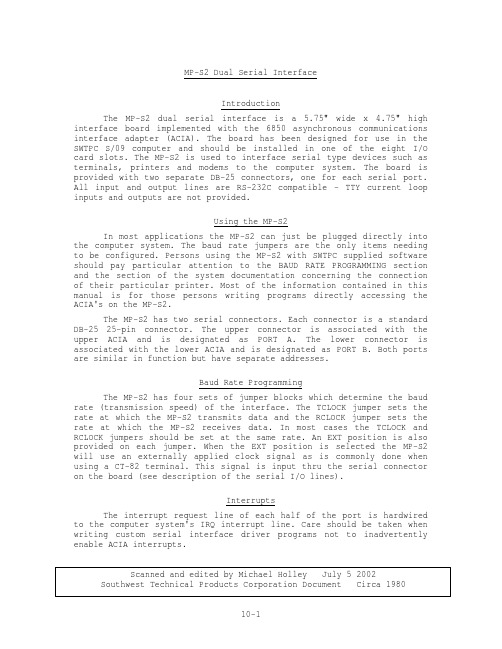
MP-S2 Dual Serial InterfaceIntroductionThe MP-S2 dual serial interface is a 5.75" wide x 4.75" high interface board implemented with the 6850 asynchronous communications interface adapter (ACIA). The board has been designed for use in the SWTPC S/09 computer and should be installed in one of the eight I/O card slots. The MP-S2 is used to interface serial type devices such as terminals, printers and modems to the computer system. The board is provided with two separate DB-25 connectors, one for each serial port. All input and output lines are RS-232C compatible - TTY current loop inputs and outputs are not provided.Using the MP-S2In most applications the MP-S2 can just be plugged directly into the computer system. The baud rate jumpers are the only items needing to be configured. Persons using the MP-S2 with SWTPC supplied software should pay particular attention to the BAUD RATE PROGRAMMING section and the section of the system documentation concerning the connection of their particular printer. Most of the information contained in this manual is for those persons writing programs directly accessing the ACIA's on the MP-S2.The MP-S2 has two serial connectors. Each connector is a standard DB-25 25-pin connector. The upper connector is associated with the upper ACIA and is designated as PORT A. The lower connector is associated with the lower ACIA and is designated as PORT B. Both ports are similar in function but have separate addresses.Baud Rate ProgrammingThe MP-S2 has four sets of jumper blocks which determine the baud rate (transmission speed) of the interface. The TCLOCK jumper sets the rate at which the MP-S2 transmits data and the RCLOCK jumper sets the rate at which the MP-S2 receives data. In most cases the TCLOCK and RCLOCK jumpers should be set at the same rate. An EXT position is also provided on each jumper. When the EXT position is selected the MP-S2 will use an externally applied clock signal as is commonly done when using a CT-82 terminal. This signal is input thru the serial connector on the board (see description of the serial I/O lines).InterruptsThe interrupt request line of each half of the port is hardwired to the computer system's IRQ interrupt line. Care should be taken when writing custom serial interface driver programs not to inadvertently enable ACIA interrupts.Serial I/O Line DescriptionThe following is a description of each of the lines available on each of the serial connectors on the board.DB-25 ConnectorPin Number Function1,7 ground Ground4,5 These pins are electrically connected together onthe MP-S2 board and are used to tie together the RTSand CTS lines of the terminal or printer to which itis connected.2 R DATA This is the RS-232 serial data input line to the MP-S2.3 T DATA This is the RS-232C serial data output line of theMP-S2.8 DCD This is the RS-232C DCD (data carrier detect) outputline of the MP-S2. This line is the buffered outputof the ACIA's RTS line. This line is normally notused.12 SDCD This is the RS-232C DCD (data carrier detect) inputline of the MP-S2. This line is the buffered inputof the ACIA's DCD line. This line is normally notused.19 HOLD DWN This buffered RS-232C input line is normally used totell the software driving the MP-S2 that a key onthe connected terminal is being held down. Thisfeature will be used only with SWTPC CT-82terminals. This line can be read thru the ControlLine Input Register.20 CTS This line is the CLEAR TO SEND (CTS) input of theMP-S2. When this line is RS-232 low, thetransmission of data out of the AC IA will beinhibited. This line is normally connected to thebuffer full or data terminal ready line of aterminal or printer.24 CLOCK IN This input line directly feeds the ACIA's receiveror transmitter clock input when the baud rate jumperis in the EXT position. This input is TTL compatibleand the clock frequency should be 16 times thedesired baud rate.Control Line Input RegisterThe MP-S2 has some special control line inputs which can be read by the computer. The functions of this "register" are as follows.Bit # Input Function0 Hold down input of A side serial connector (pin 19)1 Hold down input of B side serial connector (pin 19)2 +3 ¦4 + Reserved for future use.5 ¦6 ¦7 +Drive Capability/Input RequirementsAll input/output lines to the MP-S2 serial connectors except for the CLOCK IN line are RS-232C level compatible. Each output is nominally +10 volts in the high state and -10 volts in the low state. Outputs are currently limited to approximately lOmA. The CLOCK IN line is a diode protected MOS input that is TTL level compatible.ACIA ProgrammingThe writing of custom terminal and printer drivers which directly access the ACIA's on the MP-S2 requires a thorough knowledge of ACIA programming as described in the programming documentation. The MP-S2 Register Address Assignments table can be used in conjunction with the programming information to determine the proper ACIA address to use.MP-S2 Address AssignmentsThe MP-S2 serial interface should only be used in computer systems which have 16 addresses assigned per I/O card slot, such as the SWTPC S/09 system. Below are the address-register assignments for the MP-S2.Register Address Register0 Upper ACIA (A port) status/control register1 Upper ACIA (A port) data register2 - -3 - -4 Lower ACIA (B port) status/control register5 Lower ACIA (B port) data register6 - -7 - -B - -9 - -A - -B - -C - -D - -E Control Line Input Register-multiply decodedF Control Line Input Register-multiply decodedAll addresses not indicated are not decodedFor example, an MP-S2 board installed in port #2 of a S/09 system with I/O addresses at E000 would have the following assignments:E020 A port control/status register (E020 is the baseE021 A port data register address for port #2) E024 B port control/status registerE025 B port data registerE02F Control Line Input Register¦¦port No ++ Register addressPort # Base Address0 E0001 E0102 E0203 E0304 E0405 E0506 E0607 E070Serial Interface HandshakingWhen operating at high baud rates, many serial printers and terminals require that transmission from the computer be halted for short periods of time in order for the device to perform some type of "catch up" service, such as generating carriage returns, form feeds or other functions which take longer than the device's buffer memory can accommodate. The CTS line on the MP-S2 can be used for this purpose. When CTS is RS-232 high, characters will be continuously transmitted from the computer at the rate selected by the baud rate jumper. Characters are output at one tenth the baud rate speed. For example 1200 baud means characters are transmitted at the rate of 1200 ÷ 10 or 120 characters per second. When the CTS line is RS-232 low, character transmission will be inhibited. Note that this just holds up the computer and does not cause any characters to be lost. The signal in most terminals or printers that should be connected to the CTS line is normally called BUFFER FULL or DATA TERMINAL READY. Documentation supplied with the particular device should be referenced for details.MP-S2 Dual Serial InterfaceParts ListResistorsR1 4.7K ohm 1/4 watt resistor (optional)R2 4.7K ohm 1/4 watt resistorCapacitorsC8 0.1 mfd disc capacitorC1* 47 mfd 16-volt electrolyticcapacitorC2 0.1 mfd disc capacitor C9 0.1 mfd disc capacitorC3 0.1 mfd disc capacitor C10 0.1 mfd disc capacitorC4 0.1 mfd disc capacitor C11 0.1 mfd disc capacitorC5 0.1 mfd disc capacitor C12 0.1 mfd disc capacitorC6 0.1 mfd disc capacitor C13 0.1 mfd disc capacitorC7 0.1 mfd disc capacitorSemiconductorsD1* 1N4148 silicon diode (optional)D2* 1N4148 silicon diode (optional)D3* 1N4148 silicon diodeD4* 1N4148 silicon diodeIntegrated CircuitsIC1* 74LS02 quad NOR gate IC8* 1489 quad RS-232 receiverIC2* 74LS10 triple 3-input NAND IC9* 1489 quad RS-232 receiverIC3* 6850 ACIA (MOS) (optional) (optional)IC4* 6850 ACIA (MOS) IC10* 7805 5-volt regulatorIC5* 74LS240 octal buffer IC11* 78L12 12-volt regulatorIC12* 79L12 -12-volt regulatorIC6* 1489 quad RS-232 receiver(optional)IC7* 1488 quad RS-232transmitterAll components flagged with a (*) must be oriented as shown in the component layout drawingNOTE: Those parts, except for IC9, designated as "optional" are the ones necessary to expand the MP-S2 to dual port capability and are contained in the MP-SX expansion kit. IC9 is an optional integrated circuit for special applications and will not be supplied on most units.。
海康威视HiPAP HPR 400系统二进制通信协议说明书
HPR 400 Binary Communication Protocol This document describes the binary telegrams transmitted from the Operator Station in the HiPAP / HPR 400 systems. It also describes some of the ASCII sentences transmitted from and received by the Operator Station.The ASCII sentences complying with the NMEA 0183 rules are described in the APOS on-line helpDocument revisions Documentation Department Hardware/Software design Project/ProductManagementRev Date Sign Date Sign Date Sign A10.03.98 GM 24.07.98 HJP 03.08.98 JEF B15.05.03 GM 15.05.03 THG 15.05.03 JEF C03.05.04 GM 06.05.04 THG 06.05.04 JEF D(The original signatures are recorded in the company’s logistic database.)Contents1INTRODUCTION (5)1.1Definitions (5)2GENERAL TELEGRAM FORMAT (7)2.1Time of telegram transmission (8)2.2Floating point data format (8)2.3Serial line format (9)2.4Ethernet format (9)2.5ADP Ethernet header (9)3TELEGRAMS SENT FROM THE OPERATOR STATION (10)3.1Message 1, Transponder position data (10)Example (14)3.2Message 2, LBL position (15)Time Header (18)Example (18)3.3Message 4, LBL Ranges (19)Document history(The information on this page is for internal use)Rev. A Original issue.Earlier, the HPR 400 binary protocol document was distributed as anunofficial document, not included in the manuals. The last unofficialdocument was "Communication Protocol V2.1" - file name SWTS013.H /94.11.17.Rev. B Updated the Message 2, LBL position - Pos_north. Removed sections 3.4 /3.5 / 3.6 and chapter4.Rev. C Updated layout. Miner corrections in the text.1 INTRODUCTIONThis note is a technical documentation that may be changed. Pleasecontact Kongsberg Maritime before implementing the reception oftelegrams to assure that the note matches the SW version in the actualHiPAP/HPR system to be interfaced.1.1 DefinitionsThe following abbreviations are used in this document:APOS A coustic Positioning Operator Station, the “new” OperatorStation.BYTE 8 bit dataHiPAP High Precision Acoustic PositioningHPR Hydroacoustic Positioning Reference systemHSC 400HPR 400 System Controller, the “old” Operator Station.LBL Long Base Linems MillisecondsREAL 32 bit floating point dataREAL_64 64 bit floating point dataROV Remotely Operated VehicleSSBL Super Short Base LineTD TransducerTP TransPonderWORD_16 16 bit dataAPOS is the Acoustic Positioning Operator Station with Windows.All telegrams are implemented in the APOS.HPR 400 and HiPAP are two different types of transceivers. Theymay both be connected to an APOS Operator Station. The telegramsare delivered by the Operator Station, and the format is independent ofthe physical units involved.Later in the note, the term The system means the HiPAP / HPR 400system. The term The Operator Station is used for APOS.The binary telegrams and the ASCII sentences are the transmitted tothe Com ports and to the Ethernet as specified in the configurationmenus in the Operator Station. The same telegram may be configuredto be sent to many, to one or to none destinations.The following “terms” are used:X - POSITION Athwart ship distance to transponder, positivedirection towards starboard.Y - POSITION Fore and Aft ship distance to transponder,positive direction forward.Z - POSITION The transponder depth, positive directiondownwards.SLANT RANGE The distance to the transponder.COURSE Vessels heading, 0 - 360 degrees, positivedirection turning clockwise.ROLL Vessels roll, -180 -, 0, - 180 degrees, positivedirection is vessels port side up.PITCH Vessels pitch, -180 -, 0, - 180 degrees, positivedirection is bow up.Positive vessel y-axis is forward, positive vessel x axis is towards starboard and positive vessel z-axis is downwards. This is a left-hand coordinate system.2 GENERAL TELEGRAM FORMATThe binary telegrams transmitted on asynchronous serial lines followthe same general format with telegram heading and telegram tail. Thecontent of the data block depends on the message type, as describedfor each message.The telegrams transmitted on Ethernet have another heading, asdescribed in 2.4 and 2.5.Index Content Sizecharacter BYTE000 Start001 Block length N WORD_16type BYTE003 Message004 Destination BYTE005 Data Block with N bytesN+5 Sumcheck WORD_16character BYTEN+7 StopStart character The start character is 55 hex.Block length The block length defines the length of the data block.Message type The message type defines the message transmitted. It is a numberbetween 1 and 255.Destination The destination defines the device to which this telegram istransferred. It is not in use, and it is always set to 0.Data block The data block contains the message itself.The length N depends on the Message type. The data block for thedifferent message types are explained in the next chapters.Sumcheck The sumcheck is the 16 bit sum of all bytes in the telegram, exceptthe sumcheck itself and the stop character. The sum is calculated bybyte+byte addition.Stop character The stop character is equal to 0AAH.Note !The start character and the stop character are not unique. They mayalso occur as data within the telegram.2.1 Time of telegram transmissionThe time delay between the end of one telegram and the start of thenext one is at least 30 ms. It separates the telegrams.2.2 Floating point data formatBoth 32 bits and 64 bits floating formats are used in the telegrams.They are coded according to the IEEE standard 754. 32 bits floatingnumbers use the single precision data format. They are named REALthroughout the note. 64 bits floating numbers use the double precisiondata format. They are named REAL_64 throughout the note.The REAL format occupies 4 contiguous bytes of memory,(32 bits).SIGN EXPONENT SIGNIFICANT31 30 23 22 0Sign Sign = 0 if value is positive or zeroSign = 1 if value is negative.Exponent The exponent field contains a value offset by 127. The actualexponent can be obtained from the exponent field by subtracting127. The field is zero if the REAL value is zero.Significant The byte with the lowest address contains the least significant 8 bitsof the significant, and the byte in the highest address contains the signand the 7 most significant bits of the exponent.The REAL_64 format occupies 8 contiguous bytes of memory asshown below. The explanation of the fields is similar to theexplanation for REAL, except that the exponent is biased with 1023instead of 127.SIGN EXPONENT SIGNIFICANT63 62 52 51 02.3 Serial line formatThe serial line format is:Baud rate: Selectable between 300 and 38400 baud.The default value is 9600 baud.Parity: noneData bits: 8Stop bits: 1The least significant byte (bit 0-7) is transmitted first in bothWORD_16s, REALs and REAL_64s, followed by the moresignificant bytes.2.4 Ethernet formatWhen the telegrams are sent to external units via Ethernet, they aresent as an UDP message. They can be sent as individual messages oras broadcast messages.The telegram contains the "Message type" and the "Data Block" inaddition to the UDP blocks.Index Content Size0 Messagetype BYTE1 Data block with N bytesThe meaning of the "Message Type" and the "Data Block" is asdescribed in the start of the chapter for the serial lines.2.5 ADP Ethernet headerThe Kongsberg Maritime ADP header consists of 16 bytes. Theyreplace the message type in the normal header explained above. TheKongsberg Maritime ADP header is only used when explicitlyrequested in the Operator Station menus.3 TELEGRAMS SENT FROM THE OPERATORSTATION3.1 Message 1, Transponder position dataThe position message telegram contains SSBL transponder positiondata and sensor data related to the position measurement. It istransmitted each time a new position is calculated.Block content SizeTp_index WORD_16Operation_mode BYTESync_mode BYTETp_type BYTETp_operation BYTEPos_data_form BYTEReply_status BYTEFilt_X_pos REALFilt_Y_pos REALFilt_Z_pos REALX_pos REALY_pos REALZ_pos REALSlant_range REALP_course REALP_roll REALP_pitch REALTd_beam BYTETd_type BYTETd_num WORD_16Diagnostic WORD_16Stand_dev REALInstr_data (*) REALTp_index defines the Tp for which the position is valid.It is a number from 1 to 298. The indexes below 100 are for the lowfrequency Tps (The Axx Tps), the indexes between 100 and 200 arefor the medium frequency Tps (The Bxx Tps), and the indexesbetween 200 and 298 are for the high frequency Tps (The Cxx Tps).Examples: A02 is coded with Tp_index 2.B01 --“-- 101.B56 --“-- 156.Operation_mode Contains the Operation mode of the transceiver.00 equals standard navigation mode.01 " simulated position test mode. (Training)Sync_mode Contains the synchronization mode of the transceiver.0 equals No synchronization.1 " Sequence sync.2 " Interrogation sync.Tp_type Defines the transponder type:000 equals transpondertransponder001 " depthtransponder002 " inclinometer003 " diff. incl. transpondertransponder004 " compass005 " acoustic control transponder006 " beaconbeacon007 " depth010 " responder drive 1011 " responder drive 2012 " responder drive 3013 " responder drive 4Tp_operation Defines the operation mode of the transponder:000 equals fixed standard transponder-------"-----------001 " mobilePos_data_form Defines the position coordinate format:Bit 0 = 0 vessel oriented, cartesian.Bit 0 = 1 north oriented, cartesian.Bit 3 = 1 Ping count data validThe coordinates are normally vessel oriented, that is bit 0 is 0.Reply_status Defines the transponder reply status. When the whole byte is zero, thereply is ok.Bit 0 and 1 contains information about timeouts.Value 1 means timeout on the first pulse, value 2 meanstimeout on the second pulse and value 3 means timeouton the third pulse.Bit 2 set Ambiguity error X angle.Bit 3 set Ambiguity error Y angle.Bit 4 set Reply rejected by the software filter.Bit 5 set VRU or gyro error. The position is calculated with zerocourse and/or zero roll and pitch. The VRU and/or gyroerror is reported in the DIAGNOSTIC parameter.Filt_X_pos The filtered x - position coordinates of the transponder. Transpondershorizontal athwart ship distance from reference point. A meter valuein REAL format.Filt_Y_pos The filtered y - position coordinates of the transponder. Transpondershorizontal fore and aft ship distance from reference point. A metervalue in REAL format.Filt_Z_pos: (Depth) The filtered z - position coordinates of the transponder. Transpondersvertical distance from reference point. A meter value in REALformat.X_pos The raw x - position coordinates of the transponder. Transpondershorizontal athwart ship distance from reference point. A meter valuein REAL format.Y_pos The raw y - position coordinates of the transponder. Transpondershorizontal fore and aft ship distance from reference point. A metervalue in REAL format.Z_pos: (Depth) The raw z - position coordinates of the transponder. Transpondersvertical distance from reference point. A meter value in REALformat.Slant_range The direct raw slant range from the vessel's transducer to thetransponder. A meter value in REAL format.P_course The vessels course at the time of transponder position measurement.A value in REAL format, 0 to 360 degrees.P_roll The vessels roll at the time of transponder position measurement. Avalue in REAL format, +/-180 degrees.P_pitch The vessels pitch at the time of transponder position measurement. Avalue in REAL format, +/-180 degrees.Td_beam Defines the transducer beam, 0=wide, 1=narrow.Td_type defines the transducer type.0 equals 30 kHz wide beam only1 " 30 kHz wide/medium beam2 " 30 kHz wide/narrow beam3 " 30 kHz PMT-300, wide/wide extendedbaseline.wide/medium4 " 15kHzLBLkHz5 " 30LBL6 " 15kHz7 " 30 kHz SSBL NMT-3018 " 30 kHz SSBL tracking td-erkHzHiPAP9 " 30Td_num defines the transducer number 1 to 4 used in the positioning.Diagnostic Defines the transceiver hardware status.Error information Error index15 87 0The least significant byte of this WORD_16 parameter contains anindex, defining one error. If there is more than one error, the indexwill alter between the error indexes. The most significant byte of theparameter contains additional information for the error reported bythe index.The error indexes are reserved according to the following plan:1 to 31 General errors32 to 63 Application specific errors64 to 255 Debug diagnostics.The General errors are:reset1 HW2 Fatal transceiver errorerror3 VRUerror4 Gyro5 External serial line error6 Transmittererrorerror7 DSP8Tracking td errorWhen the Operator unit receives an error index, it is displayedtogether with the additional information. The additional informationis displayed as a hex number. The meaning of the numbers isexplained in the Operator's manual.Stand_dev The expected accuracy of the position. It is based on the covariance data calculated for the SSBL position. It is equal to the statistical sumof the major and minor semi axes of the error ellipse displayedaround the position.Instr_data (*) This is only used if any of the below cases are true:If the message contains data from a Inclinometer transponder,( Tp_type = 2 or 3 ), the first two reals contain the Inclination of thetransponder. The first contains X inclination and the second containsthe Y inclination.If the message contains data from a compass transponder,( Tp_type = 4 ), the first real in Instr_data contains the heading of thecompass transponder.If the message contains data from a depth transponder,( Tp_type = 1), the first real in Instr_data contains the depthmeasured by the transponder.If bit 3 in Pos_data_form is set, the first real in Instr_data contains theping count from the transponder with resolution million ping.If Td_type is tracking td, the last real value contains the tracking tdangle.E xampleTelegram:55 3a 00 01 00 94 00 01 00 00 00 00 00 fc e4 c9 42 72 46 6e c247 cd 80 40 bb ed c9 42 25 85 6e c2 c2 cc 8c 40 80 5b e8 42 0000 00 00 00 00 00 00 00 00 00 00 01 01 02 00 00 00 58 5c 00 40b0 11 aaThe data block of the telegram decoded:TpOmSmTtToPfSt X Y Z148 1 0 0 0 0 0 100.95 -59.57 4.03100.96 -59.63 4.40Rang Crs Roll Pitc TbTtT#Diag Std116 0.0 0.00 0.00 1 1 2 0 2.013.2 Message 2, LBL positionThe LBL position telegram contains a position relative to the origin ofthe Tp array. The position is of the vessel or of another object. Thetelegram is transmitted each time a new position is calculated. If theTransponder array is north oriented, the coordinates are relative to trueNorth, else they are relative to local north.Block content SizeSequence_number WORD_16Time_header (7) BYTEInterrogation_age WORD_16Tp_array BYTETd_num BYTEPos_east REAL_64Pos_north REAL_64Depth REALHor_err_ellipse_direction REALHor_err_ellipse_major REALHor_err_ellipse_minor REALZ_standard_deviation REALPos_type BYTEPos_status BYTEP_course REALP_roll REALP_pitch REALDiagnostic WORD_16 Sequence_number The sequence number is incremented for each LBL interrogation. It isreset each time LBL positioning is started. Range 0 - 65535.Time_header See subchapter below.Interrogation_age Time since interrogation of transponder array. The resolution is 1ms.Tp_array When the LBL position is calculated in Navigation mode, it containsthe Tp array number in use (1 and upwards).When the position is calculated in Training mode, it contains 255.Td_num Defines the transducer number in use.1 to 4 means td 1 to 4 on transceiver 15 to 8 " 29 to 12 " 313 to 16 " 40 has a special meaning. Then the position is calculated based onmeasurements on more than one transducer.Pos_east Pos_north The East and North coordinate of the position in meters. Positive East value is towards east, and positive North value is towards north.The coordinates are local coordinates.The HSC 400 also includes global UTM coordinates.Depth The depth coordinate in meters. Positive value is downwards.It is the vertical distance from the sea level to the reference point ofthe object being positioning.Hor_err_ellipse_direction Each LBL position has an one sigma error ellipse associated with it. The direction is the angle in degrees between the north axis and the major axis of the ellipse.Hor_err_ellipse_majorThe major semi axis of the error ellipse.Hor_err_ellipse_minorThe minor semi axis of the error ellipse.Z_standard_deviationThe standard deviation of the depth.Pos_type 0 - Position of the vessel1 - Position of ROV1: :16 - Position of ROV1617 - Position of TP range Position no 1: :20 - Position of TP range Position no 4Bit 7 is 0 if the coordinates are local. It is set if the they are UTMcoordinates.Pos_status This variable tells the status of the position calculation. The statuses with an asterisk in the table below are so serious that no position iscontained in the telegram.position.0 Ok1 The measured ranges match badly the calculated position. Therange residuals are big.2The position calculation did converge in the horizontal plane, but not vertically.3The calculation of the interrogation time in MuLBL mode didnot converge.16* Too few ranges are measured.17* The position calculation does not converge.18* Internal HPR computation error.19* No initial position is calculated.P_course An average of course read at the time of pulse arrival.P_roll An average of roll read at the time of pulse arrival.P_pitch An average of pitch read at the time of pulse arrival.Diagnostic See Message 1, Transponder position data.T ime HeaderThe format of the Time_header is:BlockcontentSize Index Resolution Range Day BYTE1Day1-31 Month BYTE11Month1-12 Year BYTE21Year0-99 Hours BYTE31Hour0-23 Minutes BYTE 41Minute0-59 Seconds BYTE 5 1 Second 0-591/100th seconds BYTE 6 1/100second0-100It defines the clock when the position is valid.E xampleTelegram:55 41 00 02 00 08 00 18 07 62 0d 2b 23 4a f8 0a ff 02 7a a5 cf f8 d3 fc 68 40 3d e2 a3 fb 5d 14 59 c0 70 01 9c c0 ef b3 a8 41 ff 3a 07 3e da a1 fc 3d ca 39 18 3e 00 00 00 00 00 00 00 00 00 00 00 00 00 00 00 00 50 17 aaThe data block of the telegram decoded:Seqno ddmmyyhhmmss.hh Age Ar Td East8 240798134335,74 2808 ff 2 199.90North Depth Dir Major Minor Dsigm Pt Ps-100.32 -4.88 21 0.13 0.12 0.15 0 0Crs Roll Pitch Diag0.0 0.00 0.00 03.3 Message 4, LBL RangesThe LBL_ranges message contains raw measured ranges to thetransponders, and VRU and compass data. This Message istransmitted just after the Message 2 (LBL position). The twomessages have the same sequence number.Block content SizeSequence_number WORD_16Range_age (8) WORD_16Tp_array BYTETd_num BYTEOperation_mode BYTESync_mode BYTEPos_type BYTEReply_status (8) BYTERange (8) REALP_course REALP_roll REALP_pitch REALDiagnostic WORD_16Range_age, reply_status and range consist of a list with 8 entries, onefor each transponder.Sequence_number The sequence number is incremented for each LBL interrogation. It isreset each time LBL positioning is turned ON. Range 0 - 65535.Range_age Time since reception of the range. Resolution 1ms.Tp_array When the LBL position is calculated in Navigation mode, it containsthe Tp array number in use (1 and upwards).When the position is calculated in Training mode, it contains 255.Td_num Defines the transducer number in use.1 to 4 means td 1 to 4 on transceiver 15 to 8 " 29 to 12 " 313 to 16 " 4Operation_mode See Message 1, Transponder position data.Sync_mode contains the synchronization mode of the transceiver.0 equals No synchronization.1 " Sequence sync.2 " Interrogation sync.Pos_type 0 - Position of the vessel1 - Position of ROV1: :16 - Position of ROV1617 - Position of TP range Position no 1: :20 - Position of TP range Position no 4Reply_status_n Defines the reply status. When bit 0 to 5 are zero, the measurement is OK.Bit 0 and 1 contains information about timeouts.Value 1 means timeout on the first pulse, value 2 meanstimeout on the second pulse and value 3 means timeouton the third pulse.Bit 2 set Ambiguity error or angle rejected X angle.Bit 3 set Ambiguity error or angle rejected Y angle.Bit 4 set Range rejected by the software filter.Bit 5 set Vru or gyro error. The position is calculated with zerocourse and/or zero roll and pitch. The VRU and/or gyroerror is reported in the DIAGNOSTIC parameter.Bit 6 and 7 contain information about what is measured. The contentsof the two bits are either 00 (no measurement), 80H (only the range ismeasured) or C0H (both the range and the directions are measured).Bit 7 set The range is measured OK.Bit 6 set The SSBL directions are measured OK.Range_n The measured range to the transponders.P_course An average of course read at the time of pulse arrival.P_roll An average of roll read at the time of pulse arrival.P_pitch An average of pitch read at the time of pulse arrival.Diagnostic See Message 1, Transponder position data.。
PowerBox-Systems P2-ServoBridge2 产品说明书

INSTRUCTION MANUAL P-ServoBridgeDear Customer,we are delighted that you have chosen the P² ServoBridge from PowerBox-Sys-tems.The P²-ServoBridge is a multi-function adapter for connecting conventional PWM servos to various bus systems, featuring an adjustable electronic fuse. The P²-Ser-voBridge can also be used as an over-current power-off device at normal receiver outputs with a PWM signal.When used in conjunction with PowerBox, Jeti or Futaba radio control systems the P²-ServoBridge transfers telemetry data such as voltage, current and temperature to the transmitter. Additional data, including peak current or average current, are helpful in optimising the adjustable fuse.When used with the PowerBox Core and Atom, and also with Jeti radio control systems, all the device’s parameters can be adjusted from the transmitter; with all other systems adjustments are carried out using the Royal SR2 and Competition SR2. A further adjustment facility is available using the PC-Terminal program and a USB adapter.Our website includes a range of factory-made cables and distributors for the wiring in your model; they are available in various sizes and conductor cross-sections. For wiring in the model you will find pre-assembled cables and distributors in vari-ous sizes and cross-sections on our website.We wish you much pleasure and success with the PowerBox P²-ServoBridge!Features:Automatic detection of the bus system in useCan be used with P²-BUS, S.BUS2, SRXL/UDI or PWMTelemetry data for PowerBox, Jeti and Futaba radio control systemsCurrent, voltage and temperature acquired at the servo itselfAdjustable at the transmitter with PowerBox and Jeti radio control systems Unrestricted choice of bus channelVariable PWM frame rate: 12ms, 14ms, 16ms and 18msAccurately adjustable electronic fuseAutomatic fuse reset functionFacility to set two separate cut-off currents and timesFuse immune to wear or ageing effectsFuse not temperature-dependentLED display of power-off processesCan be updated via USB interfaceCompact design: 35mm x 12mm x 4mmLow weight: 4g1. INSTALLATIONThe most efficient way of mounting the P²-ServoBridge is to attach it to a metal surface on the servo. As this ensures optimum temperature measurement.To transfer the temperature of the servo case to the sensor of the P²-ServoBridge, apply a small amount of heat-conducting paste to the hole in the sensor as shown in the illustration (1), then wipe it off flush.12Remove the backing film from the adhesive tape once you have done this (2).34Stick the P²-ServoBridge to the underside or one side of the servo, to suit the installation in your model (3).Now connect the output of the ServoBridge to the servo input socket (4).To minimise losses between the P²-ServoBridge and the servo we recommend that you shorten the servo cable and crimp a new connector (Order No. 1060) to the end.2. SET-UPThe P²-ServoBridge operates with a range of bus systems as well as standard PWM servo signals. All signals are detected automatically, which means that the device is ready to use immediately. The default settings are: Channel 1, fuse set for servos rated at 15kg/cm to 25kg/cm output torque. The following adjustment facilities are available at your transmitter or in PC-Terminal:2.1 OUTPUT CHANNELAt this point you can select the channel to be derived from the bus signal: this will be generated as a PWM servo signal.2.2 FRAME RATEThe frame rate refers to the speed at which the PWM signal is repeated at the ServoBridge’s output. Modern digital servos generally operate without problem at the 12ms setting, but the frame rate should be set to the slower 18ms value for use with earlier analogue servos. If in doubt, your servo manufacturer will be able to provide accurate information.2.3 SERVO TYPEFour different pre-set servo templates can be selected at the P²-ServoBridge: Micro, Midi, Standard and Hi-Torque. Of course, you can also adjust the set values for the two fuse thresholds individually if you wish.The table below is designed to help you assign your servo to the appropriate category:2.4 TRIP CURRENT AND TRIP TIMEThe P²-ServoBridge has two current thresholds which can be set to different valu-es, as well as the associated trip time.This feature enables you to set one threshold which causes the fuse to trip if the current value is exceeded for a significant period. The second threshold then swit-ches the power off if a higher current peak of shorter duration occurs.An example:Trip current 1: 5.0ATrip time 1: 2000msTrip current 2: 8.0ATrip time 2: 500msThe fuse switches the power off if a current of 5.0A is exceeded for at least two seconds, and also if 8.0A is exceeded for half a second.If you don’t wish to set two different threshold values, simply set both trip currents and times to the same value.3. FUSE FUNCTION, RESET FUNCTIONThe electronic fuse is very precise in operation, and can be set accurately to suit any application. In contrast to the commonly used polyfuses, the power-off current does not vary with external temperature. The cut-off characteristics of electronic fuses do not vary even if used frequently, i.e. the device continues to work reliably even over a period of years.A further advantage of electronic fuses is that it is possible to set two different cut-off thresholds, as mentioned above. Excessive continuous current can damage a servo just as easily as a brief period of higher (peak) current - for example, as a result of overheating. Electronic fuses are able to cope with both scenarios.The automatic Reset function attempts to restart the consumer unit (servo) after it has been switched off. This is accomplished by switching the fuse on again, and measuring the current. If the current is above half the set thresholds, the fuse immediately switches off again. This procedure is repeated ten times at interva-ls of one second before the fuse switches off permanently. The frequency of the power-off actions is indicated by the flashing LED.4. LED FUNCTIONSThe two-colour LED can display various operational states:LED constant blue: bus system detected, fuse on. No power-off events.L ED flashing blue: bus system detected, fuse on, number of flashes indicates number of power-off events.L ED flashing red: bus system detected, fuse off, number of flashes indica-tes number of power-off events. The automatic reset function was unable to restart the consumer unit within the set parameters.L ED flashing violet: no bus system detected: the P²-ServoBridge is in Terminal USB mode.5. BUS-OPERATION, P²-SERVOBRIDGE SET-UP FACILITIESVarious methods can be employed to set up and adjust the P²-ServoBridge.A greater or lesser quantity of data can be transferred depending on the bus system in use. Several systems allow the P²-ServoBridge to be set up from the transmitter. The table below provides an overview of the integral functions:5.1 I N CONJUNCTION WITH POWERBOX CORE AND ATOM TRANSMITTERSWITH P²-BUSIf you wish to adjust the P²-ServoBridge using a PowerBox transmitter, connect the unit to the P²-BUS socket at the receiver or the PowerBox Royal SR2, and carry out a Rescan.If multiple P²-ServoBridges are installed in the model, the address should imme-diately be established. The transmitter automatically sets the address to a vacant location when you press the X->Y button.The P²-ServoBridge now appears in the list as a sensor, and from here you can access the menu in order to enter your preferred settings.Any additional ServoBridges should be connected in the same manner.5.2 I N CONJUNCTION WITH THE POWERBOX ROYAL SR2 OR POWERBOXCOMPETITION SR2Both these PowerBoxes feature a P²-BUS menu point. If you select this point, you are asked to connect the P²-ServoBridge to the DATA output. The PowerBox now reads out the menu, and you can carry out all the required adjustments using the screen.We included this feature in order to offer a quick, simple method of setting up the ServoBridge - regardless of the radio control system you are using.You can now connect the ServoBridge to one of the P²-BUS outputs on the PowerBox Royal SR2.5.3 I N CONJUNCTION WITH A JETI TRANSMITTER WITH EX-BUSYou can use the JetiBox menu to set up theP²-ServoBridge for use with a PowerBox RoyalSR2, or for operation at one of your receiver’sEX-BUS outputs. This is accomplished byconnecting the P²-ServoBridge to an EX-BUSoutput on your receiver, where you can accessMX to set the output channel and the fuse.However, the Jeti system only allows theconnection of one P²-ServoBridge to each EX-BUS output at the receiver! Since the EX-BUSdoes not feature sensor addressing, it is not possible to implement arrangements such as Y-lead distribution - as is possible with the P²-BUS.Please note that changing the output channel alters the ID of every ServoBridge. For example, it is possible to connect two P²-ServoBridges to two of the receiver’s EX-BUS outputs, and receive telemetry data from both of them.5.4 IN CONJUNCTION WITH A FUTABA TRANSMITTER WITH S.BUS2The S.BUS2 can accommodate up to 31 sensor values (slots). With this system each P²-ServoBridge transfers four sensor values: current, voltage, capacity and temperature. Up to seven ServoBridges can be connected directly to the receiver’s S.BUS2 output using Y-leads.The USB interface and the Terminal PC program are used to select the slots to be used, the output channel and the fuse settings.The P²-ServoBridge is not registered at the transmitter: simply access the sensor list at the transmitter, and tap on the slot which you have already set for the ServoB-ridge in Terminal. Select the sensor CURR-1678 for this slot; this sensor occupies three slots. Immediately after these three slots you should select the temperature sensor TEMP-1713, which takes up one further slot.You can use 1, 5, 9, 13, 17, 21 and 25 as starting slots.5.5 SRXL/UDIThe P²-ServoBridge is also compatible with uni-directional bus systems. For example, a Multiplex M-Link receiver with SRXL output can be used as the basis for a bus wiring arrangement; the SRXL bus offers up to sixteen channels. The USB interface and PC-Terminal are used to define which channel is to be generated at the output, and to adjust the fuse.5.6 PWM SERVO SIGNALThe P²-ServoBridge can also be connected to a normal receiver output to provide over-current protection for your servo. A typical and popular application is to prevent excessive currents drawn by retract servos in model gliders.The fuse is set up using the USB interface and PC-Terminal.6. DIMENSIONS7 SET CONTENTSP²-SERVOBRIDGEHEAT-CONDUCTING PASTEINSTRUCTIONS8 SERVICE NOTEIn order to be able to offer our customers good service, a support forum has been set up for all questions concerning our products. Please use the support forum before contacting us by phone.You can find the forum at the following address:9 GUARANTEE CONDITIONSWe place particular emphasis on a high level of quality.Due to this quality management, for development and production, we are able to grant a warranty of 24 months from the date of sale on our products. The warranty consists of the fact that during the warranty period, proven material defects will be repaired by us free of charge.10 LIABILITY EXCLUSIONWe cannot monitor compliance with the installation instructions, the conditions of the P²-ServoBridge or the maintenance of the entire remote control system.Liability for damage and consequential damage caused by the device or the use of the same is excluded!We wish you every success in using your new P²-ServoBridge!Donauwörth, November 202111/2021PowerBox-Systems GmbH Ludwig-Auer-Straße 586609 DonauwoerthGermany+49-906-99 99 9-200+49-906-99 99 9-209。
安徽帕特里科技COMODI-P2S二代门禁系统说明书

u Digital Acoustic Feedback Suppression u Discussion control without operator u Controls up to 150 contribution devices uBuilt-in monitor loudspeakerThe Control Unit (CU) is the heart of the CCS Ultro Discussion System and supplies the power for all delegate and chairman units in the system. The unit also controls the chairman and delegate unitmicrophones, as well as providing connections for audio inputs and outputs.FunctionsDigital acoustic feedback suppression (CCS‑CUD)The digital acoustic feedback suppression facility automatically eliminates acoustic feedback (also known as ‘howling’ or ‘Larsen effect’). This gives better speech intelligibility by allowing the speaker volume to be turned up as loud as required without any risk of feedback.Discussion control without operatorThe CU can be setup to operate standalone without the need for an operator. The following 5 modes can be chosen using a rotary control on the unit’s top panel:Open mode – allows selection of one to fourmicrophones (excluded chairmen microphones) which can be simultaneously active•Open mode with auto-switch-off – allows selection of one to four microphones (excluded chairmenmicrophones) which can be simultaneously active. If the delegate does not speak for 30 seconds,microphones are automatically switched off•Override mode – delegates can override each other simply by activating their microphones. Only one microphone can be active at any one time. (Note: In override mode, delegates cannot override chairmen)•Chairman only mode – only chairmen can speak.Delegate microphones cannot be activated, even when a chairman is not speaking•Test mode –checks if system connections are correct.All microphone light rings and contribution unit LEDs light up to indicate that units are properly connectedSupplies power for up to 50 contribution units The CU has two trunk outputs for the loop-through connection of contribution units. It is possible to connect 25 contribution units to each trunk output,with a maximum system cable length of 100 m (109.3yards).Provides control for up to 150 contribution units Up to 3 CUs can be used together in a discussion system to power and control a maximum of 150contribution units. In this configuration a single CU acts as a master controller for the entire system.Built-in monitor loudspeakerThe built-in monitor loudspeaker and headphone socket allow the conference to be monitored.Interfaces the system with external equipmentThe following equipment can be interfaced to the CCS Ultro Discussion System through the CU:•External wired or wireless microphone – for guest speakers or audience participation. (Note: The external microphone is muted when the priority button on a chairman unit is pressed, and when the system is operating in ‘chairman only’ mode)•External PA system – for transmitting the proceedings to an audience in the same room or an adjacent room •Tape recorder – for external recording and playing back meetings and discussions•Audio equipment – for providing background music •Telephone coupler – to allow a remote delegate to participate via telephone•External audio processing – an insertion connector is providedControls and Indicators Top•Mains on/off switch•Loudspeaker volume control, for setting output level of loudspeakers of contribution units. This control also determines the maximum level for theheadphone outputs of the contribution units and the CU.•Microphone mode rotary switch, for setting the number of simultaneously active microphones, and selecting one of the four operation modes (plus test mode)•Power on LEDBack•On/off switch for digital acoustic feedback suppression facility (CCS‑CUD)•Microphone input gain adjustment•External recorder input gain adjustment •Insertion connector bypass switchInterconnections Top• 1 x 3.5 mm (0.14 inch) stereo headphone socketBack• 1 x AC input• 2 x 7-pole circular female connectors, trunk in/out loop through interconnection• 1 x 3-pole female XLR connector, microphone input (can be used as line input by included 50dB attenuator)• 1 x Cinch connector pair, line input/output• 1 x Cinch connector pair, telephone input/output • 1 x Cinch connector pair, insertion input/output • 2 x Cinch connector pairs (R/L channel), externalrecorder input/outputParts includedponent 1Control Unit 150 dB Attenuator 1User manual 1Power cordTechnical specifications ElectricalMechanicalOrdering informationCCS‑CU Control UnitCCS 900 control unit, supplies power for all delegateand chairman units in the system, as well as the unitmicrophones, provides connections for the audioinputs and outputs.Order number CCS-CUCCS‑CUD Control Unit with DAFSCCS 900 control unit with the DAFS (Digital AcousticFeedback Suppression) facility, supplies the power forall delegate and chairman units in the system, as wellas the unit microphones, provides connections for theaudio inputs and outputs.Order number CCS-CUDCCS-CU-JP Control Unit (JP)CCS 900 control unit, supplies the power for alldelegate and chairman units in the system, as well asthe unit microphones, provides connections for theaudio inputs and outputs. Japanese version.Order number CCS-CU-JPCCS-CUD-JP Control Unit with DAFS (JP)CCS 900 control unit with the DAFS (Digital AcousticFeedback Suppression) facility, supplies power for allunits in the system, as well as the unit microphones,provides connections for the audio inputs and outputs.Japanese version.Order number CCS-CUD-JPCCS‑CU‑US Control Unit (US)CCS 900 control unit, supplies power for all delegateand chairman units in the system, as well as the unitmicrophones, provides connections for the audioinputs and outputs. US version.Order number CCS-CU-USCCS‑CUD‑US Control Unit with DAFS (US)CCS 900 control unit with the DAFS (Digital AcousticFeedback Suppression) facility, supplies power for allunits in the system, as well as the unit microphones,provides connections for the audio inputs and outputs.US version.Order number CCS-CUD-USRepresented by:Americas:Europe, Middle East, Africa:Asia-Pacific:China:America Latina:Bosch Security Systems, Inc. 12000 Portland Avenue South Burnsville MN 55337, USA Phone: +1-800-392-3497 Fax: +1-800-955-6831*********************.com Bosch Security Systems B.V.P.O. Box 800025617 BA Eindhoven, The NetherlandsPhone: + 31 40 2577 284Fax: +31 40 2577 330******************************Robert Bosch (SEA) Pte Ltd, SecuritySystems11 Bishan Street 21Singapore 573943Phone: +65 6571 2808Fax: +65 6571 2699*****************************Bosch (Shanghai) Security Systems Ltd.201 Building, No. 333 Fuquan RoadNorth IBPChangning District, Shanghai200335 ChinaPhone +86 21 22181111Fax: +86 21 22182398Robert Bosch Ltda Security Systems DivisionVia Anhanguera, Km 98CEP 13065-900Campinas, Sao Paulo, BrazilPhone: +55 19 2103 2860Fax: +55 19 2103 2862*****************************© Bosch Security Systems 2014 | Data subject to change without notice 1836992779 | en, V5, 27. Nov 2014。
(售后服务)2020年POS服务系统POS终端接口说明
手机支付现场支付子系统开发指导文档P O S服务系统-P O S终端接口说明版本号:1.0.0╳╳╳╳-╳╳-╳╳发布中国移动通信有限公司研究院目录1. 范围 (4)2. 规范性引用文件 (4)3. 术语、定义和缩略语 (4)4. 网络结构 (7)5. 接口说明 (7)6. 协议栈 (8)7. 通信方式 (8)7.1. 短连接 (9)7.2. 本协议涉及的端口号 (10)8. 接口流程 (10)8.1. POS充值 (10)8.2. 消费撤销 (12)8.3. 退货 (13)8.4. 签到 (15)8.5. 批结算 (15)8.6. 回响 (16)8.7. POS终端初始化 (17)8.8. 应用程序更新 (18)8.9. 参数更新 (18)8.10. KEK更新 (19)9. IF1——POS-POS服务系统交易接口 (20)9.1. 消息域说明 (20)9.1.1. 指令说明 (20)9.1.2. 8583数据类型 (21)9.1.3. 数据元名称及其定义 (21)9.2. POS终端消息交换说明 (36)9.2.4. 消息格式说明 (36)9.2.5. 交易类 (37)9.2.6. 管理类 (41)9.3. 应答码描述 (45)10. IF2——POS-POS服务系统管理接口 (47)10.1. 协议说明 (47)10.1.7. LEN说明 (47)10.1.8. TLV 结构说明 (47)10.2. 指令说明 (50)10.3. 通讯方式 (51)10.3.9. GPRS (51)10.3.10. 串口 (53)10.4. 管理报文格式 (53)10.4.11. 符号定义 (53)10.4.12. 回响(ActiveTest) (53)10.4.13. 参数下载(DownLoadAppParameter) (54)10.4.14. 应用程序下载 (57)10.4.15. KEK下载(InitializeForKEK) (61)10.5. 应答码的处理 (61)10.5.16. 应答码描述 (61)11. 编制历史 (61)12. 附录A 编码规则 (62)12.1. POS终端号 (62)12.2. POS终端序列号 (62)12.3. 商户编号 (63)13. 附录B 各省移动公司代码 (63)前言本文档以指导移动支付系统POS服务系统和POS终端数据接口的开发为目的。
某通信公司技术规范外部接口分册

互动接口应能够 平滑地扩充
扩展原则:
互动接口连接 必须具有
安全控制机制
在满足业务需求的 前提下,使接口数据 量最少,最大限度地 减轻数据提供方压力
由数据源传送方或数据源接收方发起的接口扩展,都必须采 用现有的传输协议与模式,并与现有接口编码规则和命名规 则保持一致
接口定位
接口分类
NG1-CRM系统接口
分析结果 查询
该接口用于经营分析系统向外部系统提 在线请求—异步响应方式
供历史报表访问。
查询服务 明 细 数 据 明细数据结果数据集
查询
该接口用于经营分析系统向外部系统提 在线请求—异步响应方式
供详细数据访问。
该接口用于获取指定的个人客户的基础
获取个人客户基本属性信息
属性相关信息,包括基本属性、终端使 在线请求—同步响应方式
蓝色空心箭头表示 数据源接口
粉色空心箭头表示 互动接口
潜蓝色空心双向箭 头表示功能类接口
实心黑色箭头表示省级 经营分析内部数据流
直接从省级业务支撑系统获取相关数据,如省级NG1-BOSS、 NG1-CRM;
直接从省级外部数据源系统,如:网管系统、彩铃平台、 DSMP平台、OTA平台、WAP网关、网络信令采集子系统、 VGOP平台、ERP/MIS系统等获取相关数据;
…
清单信息 帐务信息 缴费信息
…
结算
结算清单 …
参数配置与计算原则
参数 配置
业务 计算原则 …
一级经营分析系统 接口
新业务营销体验平台
行业应用终端监控平台 …
省级外部系统接口
彩铃平台 网管系统 DSMP平台 OTA平台 WAP网关 网络信令 ERP/MIS
…
[宝典]I2S接口说明
![[宝典]I2S接口说明](https://img.taocdn.com/s3/m/0758170684254b35effd3428.png)
[宝典]I2S接口说明I2S接口I2C总线说明I2C总线百科名片I2C总线I2C(Inter,Integrated Circuit)总线是一种由PHILIPS公司开发的两线式串行总线,用于连接微控制器及其外围设备。
I2C总线产生于在80年代,最初为音频和视频设备开发,如今主要在服务器管理中使用,其中包括单个组件状态的通信。
例如管理员可对各个组件进行查询,以管理系统的配置或掌握组件的功能状态,如电源和系统风扇。
可随时监控内存、硬盘、网络、系统温度等多个参数,增加了系统的安全性,方便了管理。
目录[隐藏]详细说明1 I2C总线特点I2C总线最主要的优点是其简单性和有效性。
由于接口直接在组件之上,因此I2C总线占用的空间非常小,减少了电路板的空间和芯片管脚的数量,降低了互联成本。
总线的长度可高达25英尺,并且能够以10Kbps的最大传输速率支持40个组件。
I2C总线的另一个优点是,它支持多主控(multimastering),其中任何能够进行发送和接收的设备都可以成为主总线。
一个主控能够控制信号的传输和时钟频率。
当然,在任何时间点上只能有一个主控。
2 I2C总线工作原理2.1 总线的构成及信号类型I2C总线是由数据线SDA和时钟SCL构成的串行总线,可发送和接收数据。
在CPU与被控IC之间、IC与IC之间进行双向传送,最高传送速率100kbps。
各种被控制电路均并联在这条总线上,但就像电话机一样只有拨通各自的号码才能工作,所以每个电路和模块都有唯一的地址,在信息的传输过程中,I2C总线上并接的每一模块电路既是主控器(或被控器),又是发送器(或接收器),这取决于它所要完成的功能。
CPU发出的控制信号分为地址码和控制量两部分,地址码用来选址,即接通需要控制的电路,确定控制的种类;控制量决定该调整的类别(如对比度、亮度等)及需要调整的量。
这样,各控制电路虽然挂在同一条总线上,却彼此独立,互不相关。
I2C总线在传送数据过程中共有三种类型信号,它们分别是:开始信号、结束信号和应答信号。
G2S软交换产品介绍

PSTN TG2000/DGW
中继网关
SIPU/EGW SIPU 内置中继网关
接入层
IP话机 话机
VP300 视频话机
VS200 软电话
调度台
-4 -
广州广哈通信有限公司
核心层架构
G2S
SW9101(≤2,000线) SW9102(≤5,000线)
SW9100(≤10,000线) SW9500( ≤ 20,000线)
处理器
*支持的处理器主频不断更新中 内存类型 内存规格 存储能力 输入输出接口 电源 操作系统 机箱尺寸 registered or un-buffered DDR3 2GB 2GB 4GB
支持SAS硬盘,最大可安装8颗热插拔3.5英寸硬盘,标配2颗,292G, 集成RAID0、 1、10 VGA 1个;USB2.0 4个;PS2 2个;RJ-45网络接口2个;串口 2个 480W 220VAC 单电源,支 持直流 Redhat Enterprise Linux 5.2 深*宽= 650mm*430mm; 高度:1U 深*宽= 650mm*430mm ; 高度:2U 深*宽= 650mm*430mm ; 高度:2U 550W 220VAC(1+1)冗 余电源,支持直流 550W 220VAC(1+1)冗 余电源,支持直流
模拟网关
IP专网 专网
IP话机 IP话机 模拟话机
-22- 22-
广州广哈通信有限公司
接入层
BC6000会话边缘控制器 会话边缘控制器
提供防火墙/NAT穿越功能,实现IP地址的网络映射; 根据会话的需要修改和加强QoS标记,以提供SLAs(服务级别协议); 呼叫建立时管理连接,监管发送数据包的数目及类型,防止用户使用越权业务; 隐藏私网IP地址保护服务网络的安全,防止拒绝服务攻击(DoS)等威胁; 隐藏私网网络结构的细节,如服务器的数目和位置; 在代理呼叫接续过程中收集 用于产生话费CDR的有用信息。
2接口协议解析及应用

2接口协议解析及应用接口协议是指两个或多个系统或组件之间进行通信时所约定的数据格式、消息格式、方法调用规则等。
它定义了系统之间交互的方式和规范,从而保证了系统之间的互操作性和可扩展性。
解析接口协议的过程包括以下几个方面:1. 数据格式解析:接口协议通常定义了数据交换的格式,包括数据的编码方式(如JSON、XML等)和数据的字段和类型。
解析接口协议时需要根据协议定义的格式解析收到的数据,将其转换为系统能够处理的数据结构。
2. 消息格式解析:接口协议通常定义了消息的格式,包括消息的头部信息和消息的内容。
解析接口协议时需要解析消息的头部信息,获取消息的类型和参数等信息,并根据消息的类型解析消息的内容。
3. 方法调用规则解析:接口协议通常定义了系统或组件之间的方法调用规则,包括方法的名称、参数和返回值的类型。
解析接口协议时需要解析方法的名称和参数列表,并根据协议定义的规则进行方法调用。
应用接口协议的过程包括以下几个方面:1. 接口开发:根据接口协议的定义,开发系统或组件的接口,包括实现接口的方法和定义接口的数据格式。
接口的开发需要按照接口协议的规范进行,并根据实际需求进行适当的扩展和定制。
2. 接口调用:根据接口协议的定义,调用其他系统或组件的接口。
在接口调用时需要按照接口协议的规范传递参数,并处理接口返回的数据。
3. 接口测试:对接口进行测试,验证接口的正确性和可靠性。
接口测试可以通过模拟接口的输入和输出,检查接口返回的结果是否符合预期。
通过接口协议,不同系统之间可以进行有效的数据交换和方法调用,实现系统之间的协同工作和信息共享。
接口协议的解析和应用是系统集成和服务化的基础,能够提高系统的灵活性和可扩展性。
同时,合理设计和使用接口协议还可以提高系统的安全性和稳定性,避免系统之间的冲突和错误。
- 1、下载文档前请自行甄别文档内容的完整性,平台不提供额外的编辑、内容补充、找答案等附加服务。
- 2、"仅部分预览"的文档,不可在线预览部分如存在完整性等问题,可反馈申请退款(可完整预览的文档不适用该条件!)。
- 3、如文档侵犯您的权益,请联系客服反馈,我们会尽快为您处理(人工客服工作时间:9:00-18:30)。
当前嵌入式系统技术已得到了广泛应用,但传统嵌入式系统的人机接口多采用小键盘操作的文本菜单方式,用户操作较为不便。本文介绍了一种利用PS/2接口鼠标,在点阵LCD的单片机系统上实现图形化用户界面的方案。用窗口菜单和图形按钮取代了传统的键盘操作,具有成本低、效果好等特点,具有很强的实用性。
1 PS/2接口和协议
1.1 接口的物理特性
PS/2接口用于许多现代的鼠标和键盘,由IBM最初开发和使用。物理上的PS/2接口有两种类型的连接器:5脚的DIN和6脚的mini-DIN。图1就是两种连接器的引脚定义。使用中,主机提供+5V电源给鼠标,鼠标的地连接到主机电源地上。
1.2 接口协议原理
PS/2鼠标接口采用一种双向同步串行协议。即每在时钟线上发一个脉冲,就在数据线上发送一位数据。在相互传输中,主机拥有总线控制权,即它可以在任何时候抑制鼠标的发送。方法是把时钟线一直拉低,鼠标就不能产生时钟信号和发送数据。在两个方向的传输中,时钟信号都是由鼠标产生,即主机不产生通信时钟信号。
如果主机要发送数据,它必须控制鼠标产生时钟信号。方法如下:主机首先下拉时钟线至少100μs抑制通信,然后再下拉数据线,最后释放时钟线。通过这一时序控制鼠标产生时钟信号。当鼠标检测到这个时序状态,会在10ms内产生时钟信号。如图3中 A 时序段。主机和鼠标之间,传输数据帧的时序如图2、图3所示。2.2 数据包结构在主机程序中,利用每个数据位的时钟脉冲触发中断,在中断例程中实现数据位的判断和接收。在实验过程中,通过合适的编程,能够正确控制并接收鼠标数据。但该方案有一点不足,由于每个CLOCK都要产生一次中断,中断频繁,需要耗用大量的主机资源。
2 PS/2鼠标的工作模式和协议数据包格式
2.1 PS/2鼠标的四种工作模式
PS/2鼠标的四种工作模式是:Reset模式,当鼠标上电或主机发复位命令 0xFF给它时进入这种模式;Stream模式鼠标的默认模式,当鼠标上电或复位完成后,自动进入此模式,鼠标基本上以此模式工作;Remote模式,只有在主机发送了模式设置命令 0xF0后,鼠标才进入这种模式;Wrap模式,这种模式只用于测试鼠标与主机连接是否正确。
PS/2鼠标在工作过程中,会及时把它的状态数据发送给主机。发送的数据包格式如表1所示。
Byte1中的Bit0、Bit1、Bit2分别表示左、右、中键的状态,状态值0表示释放,1表示按下。Byte2和Byte3分别表示X轴和Y轴方向的移动计量值,是二进制补码值。Byte4的低四位表示滚轮的移动计量值,也是二进制补码值,高四位作为扩展符号位。这种数据包由带滚轮的三键三维鼠标产生。若是不带滚轮的三键鼠标,产生的数据包没有Byte4 其余的相同。
3 设计与实现
3.1 接口设计
因为PS/2鼠标接口采用双向同步串行协议,时钟脉冲信号以下皆称CLOCK 总是由鼠标产生。因此,可以考虑这种方案:鼠标的CLOCK接主机的一外中断线,数据线以下皆称DATA 接主机的某一I/O口线,如图4所示。
由于鼠标与主机之间以双向同步串行协议传送数据,若不考虑CLOCK,仅考虑DATA,则其数据帧的时序与单片机的UART异步串行时序类似。所以,采用了另一种方案:鼠标的CLOCK仍旧接主机的外中断,但鼠标的DATA接UART的接收脚RxD 。参照图4DATA改接RxD。在初始化过程中,主机利用CLOCK的外中断和RxD脚的I/O口线功能实现数据的传输。初始化完成后,切换到RxD功能即UART的接收引脚功能。因为鼠标已处于Stream模式的工作状态,这时鼠标能主动发送数据。这样,主机可以在每收到一帧数据时才中断一次。中断次数大大降低,减少了主机资源的耗用。
不过,在此方案中,必须实现另一个功能:主机波特率的自适应。因为PS/2接口的鼠标一般工作在10kHz~20kHz时钟频率。不同厂家制造的鼠标工作的时钟频率不同。嵌入设备主机要做到与不同鼠标的波特率同步和自适应,才能够正确接收鼠标传送来的数据。波特率的自适应是这样实现:鼠标上电自检时会产生一串时钟脉冲,利用鼠标时钟脉冲产生的中断,结合主机的定时器测量时钟脉冲周期,可以得出所用鼠标的时钟频率,进而求出波特率。通过设置相应的波特率寄存器,实现了波特率的自适应。
3.2 软件实现
软件实现原理框图如图5所示。
(1)鼠标初始化
最简单的初始化就是当鼠标上电自检完成后,主机给鼠标发送一个使能鼠标数据传送命令字节 (0xf4),鼠
标就会在默认设置状态下工作。主机也可实现自定义初始化,如:复位三次(Snd_CMD(0xff),Snd_CMD(0xff), Snd_CMD(0xff);设置采样率:Snd_CMD(0xf3),Snd_CMD(0x0a);设置解析度(2点/毫米):Snd_CMD (0xe8),Snd_CMD(0x01);设置缩放比例(1:1):Snd_CMD(0xe6);使能鼠标数据传送:Snd_CMD(0xf4)。鼠标每收到一个命令字节都会给出一个应答字节(0xfa)。
(2)两种方案的实现过程
两种方案的软件实现过程基本相同。只是后一种方案中,初始化时还要实现主机波特率的自适应,关闭时钟脉冲中断和打开串口中断。此后主机利用UART的接收功能接收鼠标数据。
(3)图形化人机接口(GUI)的实现
在点阵式LCD显示屏上实现图形化的人机接口界面,主要有两个方面:一个是菜单图标的实现;另一个是鼠标光标的实现。实现菜单图标,显示屏一般工作在图形显示模式。菜单图标有正常显示状态和反显状态,它们都用函数实现:voidDraw_ICON(signed int xICON, signed int yICON,unsigned char *pDatICON)。xICONyICON是图标所在位置的左上角坐标值,pDatICON是各个图标及其不同显示状态的点阵码值。反显状态是当图标被光标滑到或点取时才显现的。实现鼠标光标,又分两种情况。一种是单层显示的LCD,只能由程序画出鼠标光标。但是,当光标移动较快时,画出光标的点阵图形需要耗用较多的主机资源。另一种是有双层显示和光标功能的LCD,只需程序控制它的光标移动位置,无需程序画出光标的点阵图形,因而耗用主机资源较少,实现起来效果较好。
两种方案简单、明了,容易实现,都已在实验中得到验证。并且,后一种方案已在某一仪表系统中得到成功应用。总体来说,随着嵌入式处理器性能的不断提高,在嵌入设备中接入鼠标,既可灵活使用,也可减少因接入许多按键而占用的口线数,还能使LCD的图形化显示界面更美观、更人性化。。
