CDBU0130R;中文规格书,Datasheet资料
CDSOD323-T12C中文资料
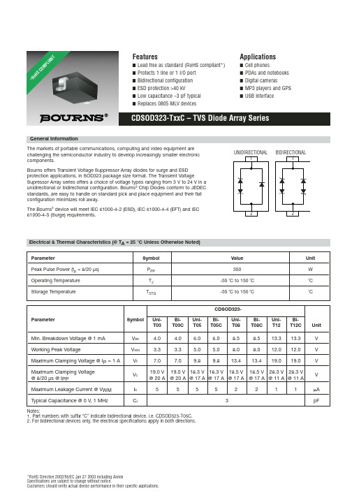
V
Working Peak Voltage
VWM
3.3
3.3
5.0 5.0
8.0
8.0 12.0 12.0
V
Maximum Clamping Voltage @ IP = 1 A Maximum Clamping Voltage @ 8/20 µs @ IPP Maximum Leakage Current @ VWM Typical Capacitance @ 0 V, 1 MHz
BiT15C
CDSOD323-
UniT18
BiT18C
UniT24
BiT24C Unit
Min. Breakdown Voltage @ 1 mA
VBR
16.7
16.7
20.0
20.0
26.7
26.7
V
Working Peak Voltage
VWM
15.0
15.0
18.0
18.0
24.0
24.0
V
Maximum Clamping Voltage @ IP = 1 A Maximum Clamping Voltage @ 8/20 µs @ IPP Maximum Leakage Current @ VWM Typical Capacitance @ 0 V, 1 MHz
10 0.01
1
10
100
td – Pulse Duration (µs)
1,000
10,000
Pulse Wave Form
120 100 80 60 40 20
0 0
tt
Test Waveform Parameters tt = 8 µs
CD4051中文资料_数据手册_参数

CD4051中文资料第14页精选内容:可订购设备状态 (1)包类型包画画引脚包数量生态计划 (2)铅/球完成 MSL峰值温度 (3) CD4053BPWR活性 TSSOP PW 16 2000无铅 (RoHS)的 CU NIPDAU等级-1-250C-UNLIM (1) 营销状况值定义如下: ACTIVE:推荐 用于新设计的产品设备. LIFEBUY:TI已经宣布CD4051该设备将停产,终身购买期限已经生效. NRND:不建议用于新设计.器件正在生 产中以支持现有客户,但TI不建议使用此部分一个新的设计.预览:设备已被宣布,但尚未投入生产.样品或提供或不提供.停产:TI已 停止生产该设备. (2) 生态计划 - 目前可能无法使用 - 请查阅获CD4051取新的可用性信息和附加信息产品内容细节.无:尚未提供铅 (无铅).无铅(RoHS):TI的术语“无铅”或“无铅”是指符合当前RoHS要求的半导体产品对于所有6种物质,包括在均质材料中 铅含量不超过0.1%的要求.在哪里设计焊接在高温下,TI无铅产品适用于特定的无铅工艺.绿色(RoHS&no Sb / Br):TI将“绿色”定 义为“无铅”,另外使用不含卤素的包装材料,CD4051包括总产品重量的0.1%以上的溴(Br)或锑(Sb). (3) MSL,Peak Temp. 根据JEDEC行业标准分类的潮湿敏感度等级和峰值焊料温度. CD4051重要信息和免责声明:本页面提供的信息代表了TI在当时的知识 和信念提供. TI根据第三方提供的信息来了解和信任,CD4051对此不作任何表示或保证这些信息的准确性.正在努力更好地整合来自第 三方的信息. TI已经采取并继续采取合理的步骤提供代表性和准确的信息,但可能没有进行破坏性测试或化学分析来料和化学品. TI和 TI供应商认为某些信息是专有的,因此CAS号码和其他限制信息可能无法发布.在任何情况下,由于此类信息引起的TI责任,均不得超 过本TI出售TI器件的总购买价格给客户每年.包装选项增补 12特别注意事项在使用独立电源的应用中 驱动V DD 和信号输入,V DD 电流能力 应该超过V DD / R L (R L =有效外部负载). 这个提 供避免永久电流或钳位动作 电源接通或 断开 时 的V DD 电源 CD4051B,CD4052B或CD4053B.图23. CD4052B的典型时分应用 测试电路 和波形 (续) .265 ℃ (SOIC - 仅限引线提示)小心:CD4051超出“绝对大额定值”列出的值可能会导致设备永久性损坏.这是一个压力只有评级和 操作的设备在这些或任何其他条件以上高于本规范操作部分所述的条件并不意味着.注意: 1.封装热阻抗按照JESD 51-7计算.电气规格 这里的常见条件:如果全表为全温度 范围,V SUPPLY =±5V,A V = +1, R L =100Ω,除非另有规定(注3)参数条件 指示温度限制 ( ℃)单位 V IS (V) V EE (V)V SS (V)V DD (V) -55 -40 85 125 25 MIN TYP MAX 信号输入(V IS )和输出(V OS )静态装置 当前
NJW0302G;NJW0281G;中文规格书,Datasheet资料

NJW0281G (NPN)NJW0302G (PNP)Preferred Devices Complementary NPN-PNP Power Bipolar TransistorsThese complementary devices are lower power versions of the popular NJW3281G and NJW1302G audio output transistors. With superior gain linearity and safe operating area performance, these transistors are ideal for high fidelity audio amplifier output stages and other linear applications.Features•ăExceptional Safe Operating Area•ăNPN/PNP Gain Matching within 10% from 50 mA to 3 A•ăExcellent Gain Linearity•ăHigh BVCEO•ăHigh Frequency•ăThese are Pb-Free DevicesBenefits•ăReliable Performance at Higher Powers•ăSymmetrical Characteristics in Complementary Configurations •ăAccurate Reproduction of Input Signal•ăGreater Dynamic Range•ăHigh Amplifier BandwithApplications•ăHigh-End Consumer Audio Products♦ăHome Amplifiers♦ăHome Receivers•ăProfessional Audio Amplifiers♦ăTheater and Stadium Sound Systems♦ăPublic Address Systems (PAs)MAXIMUM RATINGSRating Symbol Value UnitCollector-Emitter Voltage V CEO250Vdc Collector-Base Voltage V CBO250Vdc Emitter-Base Voltage V EBO 5.0Vdc Collector-Emitter Voltage - 1.5 V V CEX250VdcCollector Current - Continuous-Peak (Note 1)I C1530AdcBase Current - Continuous I B1.5AdcTotal Power Dissipation @ T C = 25°C P D150WattsOperating and Storage Junction Temperature Range T J, T stg-65 to+150°CStresses exceeding Maximum Ratings may damage the device. Maximum Ratings are stress ratings only. Functional operation above the Recommended Operating Conditions is not implied. Extended exposure to stresses above the Recommended Operating Conditions may affect device reliability.1.Pulse Test: Pulse Width = 5.0 ms, Duty Cycle < 10%.15 AMPERES COMPLEMENTARY SILICON POWER TRANSISTORS250 VOLTS, 150 WATTSDevice Package ShippingORDERING INFORMATIONTO-3PCASE 340ABMARKINGDIAGRAMPreferred devices are recommended choices for future use and best overall value.NJW0302G TO-3P(Pb-Free)30 Units/Rail NJW0281G TO-3P(Pb-Free)30 Units/Railxxxx= 0281 or 0302G= Pb-Free PackageA= Assembly LocationY= YearWW= Work WeekNJWxxxGAYWWTHERMAL CHARACTERISTICSCharacteristicSymbol Value Unit Thermal Resistance, Junction-to-CaseR θJC0.83°C/WELECTRICAL CHARACTERISTICS (T C = 25°C unless otherwise noted)CharacteristicSymbolMinMaxUnitOFF CHARACTERISTICSCollector-Emitter Sustaining Voltage (I C = 30 mA, I B = 0)V CEO(sus)250-V Collector Cutoff Current (V CB = 250 V, I E = 0)I CBO -10m A Emitter Cutoff Current (V EB = 5.0 V, I C = 0)I EBO- 5.0m AON CHARACTERISTICS DC Current Gain(I C = 0.5 A, V CE = 5.0 V)(I C = 1.0 A, V CE = 5.0 V)(I C = 3.0 A, V CE = 5.0 V)h FE757575150150150-Collector-Emitter Saturation Voltage (I C = 5.0 A, I B = 0.5 A)V CE(sat)- 1.0V Base-Emitter On Voltage (I C = 5.0 A, V CE = 5.0 V)V BE(on)- 1.2V DYNAMIC CHARACTERISTICSCurrent-Gain - Bandwidth Product(I C = 1.0 A, V CE = 5.0 V, f test = 1.0 MHz)f T 30-MHz Output Capacitance(V CB = 10 V, I E = 0, f test = 1.0 MHz)C ob-400pF160T C , CASE TEMPERATURE (°C)40601001201608014020Figure 1. Power Derating 020406080100140120P D , P O W E R D I S S I P A T I O N (W)0.010.11101001101001000V CE , COLLECTOR-EMITTER VOLTAGE (V)I C , C O L L E C T O R C U R R E N T (A )Figure 2. Safe Operating Area00.20.40.60.811.21.40.010.1110100I C , COLLECTOR CURRENT (A)Figure 3. NJW0281G DC Current GainFigure 4. NJW0302G DC Current Gainh F E , D C C U R R E N T G A I NI C , COLLECTOR CURRENT (A)Figure 5. NJW0281G Base-Emitter Voltage I C , COLLECTOR CURRENT (A)0.010.1110100Figure 6. NJW0302G Base-Emitter VoltageV B E (o n ), B A S E -E M I T T E R V O L T A G E (V )I C , COLLECTOR CURRENT (A)V B E (o n ), B A S E -E M I T T E R V O L T A G E (V )h F E , D C C U R R E N T G A I N0.050.111050-0.10.40.91.41.92.40.050.111050Figure 7. NJW0281G Saturation Voltage 0.010.11100.010.1110100I C , COLLECTOR CURRENT (A)V C E (s a t ), C O L L E C T O R -E M I T T E R S A T U R A T I O N V O L T A G E (V)0.010.11100.010.1110100Figure 8. NJW0302G Saturation VoltageI C , COLLECTOR CURRENT (A)V C E (s a t ), C O L L E C T O R -E M I T T E R S A T U R A T I O N V O L T A G E (V )0102030405060700.010.1110Figure 9. NJW0281G Current Gain BandwidthProduct I C , COLLECTOR CURRENT (A)f T , C U R R E N T G A I N B A N D W I D T H P R O D U C T (M H z )Figure 10. NJW0302G Current Gain BandwidthProductI C , COLLECTOR CURRENT (A)f T , C U R R E N T G A I N B A N D W I D T H P R O D U C T (M H z )01020304050600.010.1110PACKAGE DIMENSIONSTO-3P-3LD CASE 340AB-01ISSUE ADIM A MIN NOM MAX MILLIMETERS 19.7019.9020.10B 15.4015.6015.80C 4.60 4.80 5.00D 0.80 1.00 1.20E 1.45 1.50 1.65G 5.45 BSC H 1.20 1.40 1.60J 0.550.600.75K 19.8020.0020.20L 18.5018.7018.90U 5.00 REF P 3.30 3.50 3.70Q 3.10 3.20 3.50W2.803.00 3.20NOTES:1.DIMENSIONING AND TOLERANCING PER ASME Y14.5M, 1994.2.CONTROLLING DIMENSION: MILLIMETERS3.DIMENSION b APPLIES TO PLATED TERMINAL AND IS MEASURED BETWEEN 0.15 AND 0.30mm FROM THE TERMINAL TIP.4.DIMENSION A AND B DO NOT INCLUDE MOLD FLASH, PROTRUSIONS, OR GATE BURRS.F 1.80 2.00 2.20SEATING PLANEFUON Semiconductor and are registered trademarks of Semiconductor Components Industries, LLC (SCILLC). SCILLC reserves the right to make changes without further notice to any products herein. SCILLC makes no warranty, representation or guarantee regarding the suitability of its products for any particular purpose, nor does SCILLC assume any liability arising out of the application or use of any product or circuit, and specifically disclaims any and all liability, including without limitation special, consequential or incidental damages.“Typical” parameters which may be provided in SCILLC data sheets and/or specifications can and do vary in different applications and actual performance may vary over time. All operating parameters, including “Typicals” must be validated for each customer application by customer's technical experts. SCILLC does not convey any license under its patent rights nor the rights of others. SCILLC products are not designed, intended, or authorized for use as components in systems intended for surgical implant into the body, or other applications intended to support or sustain life, or for any other application in which the failure of the SCILLC product could create a situation where personal injury or death may occur. Should Buyer purchase or use SCILLC products for any such unintended or unauthorized application, Buyer shall indemnify and hold SCILLC and its officers, employees, subsidiaries, affiliates,and distributors harmless against all claims, costs, damages, and expenses, and reasonable attorney fees arising out of, directly or indirectly, any claim of personal injury or death associated with such unintended or unauthorized use, even if such claim alleges that SCILLC was negligent regarding the design or manufacture of the part. SCILLC is an Equal Opportunity/Affirmative Action Employer. This literature is subject to all applicable copyright laws and is not for resale in any manner.PUBLICATION ORDERING INFORMATION分销商库存信息:ONSEMINJW0302G NJW0281G。
SY8008 SY8009 datasheet 规格书
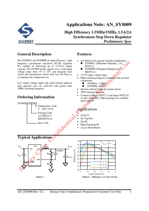
Applications Note: AN_SY8009High Efficiency 1.5MHz/1MHz, 1.5A/2A Synchronous Step Down Regulator Preliminary Spec General DescriptionThe SY8009A and SY8009B are high-efficiency , high frequency synchronous step-down DC-DC regulator ICs capable of delivering up to 1.5A/2A output currents. The SY8009 family operate over a wide input voltage range from 3V to 5.5V and integrate main switch and synchronous switch with very low RDS(ON) to minimize the conduction loss. Low output voltage ripple and small external inductor and capacitor sizes are achieved with greater than 1MHz switching frequency.Features• low Rds(on) for internal switches (top/bottom) SY8009A: 200mohm/150mohm, 1.5A, SOT23-5 SY8009B:150mohm/120mohm,2.0A, SSOT23-6 • 3-5.5V input voltage range • High switching frequency minimizes the external components SY8009A: 1.5MHz SY8009B: 1MHz • Internal softstart limits the inrush current • 100% dropout operation • Compact package: SOT23-5 and Super SOT23-6 are pin-compatible. Other packages are available upon requestsOrdering InformationSY8009□(□□ □ □ □□ □□)□ Temperature Code C: - 40°C~85°C Package Code: AA:SOT23-5 EB:SSOT23-6 Spec CodeApplications• • • • •LCD TV Set Top Box Net PC Mini-Notebook PC Access Point RouterTypical ApplicationsVININ EN LXL C1(opt.) R1VOUTCINFB GNDCOUT R2Figure 1Efficiency (%)Figure2Efficiency vs Load CurrentAN_SY8009 Rev. 0.2Silergy Corp. Confidential- Prepared for Customer Use Only1AN_SY8009Pinout (top view)(SY8009A, SOT23-5)(SY8009B, SSOT23-6)Top Mark: ADxyz for SY8009A , ASxyz for SY8009B (Device code: AD for SY8009A and AS for SY8009B, x=year code, y=week code, z= lot number code) Pin Name EN GND LX IN FB Pin Number 1 2 3 4 6(SSOT23-6) Pin Description Enable control. Pull high to turn on. Do not float. Ground pin Inductor pin. Connect this pin to the switching node of inductor. Input pin. Decouple this pin to GND pin with at least 1uF ceramic cap. Output Feedback Pin. Connect this pin to the center point of the output resistor divider (as shown in Figure 1) to program the output voltage: Vout=0.6*(1+R1/R2).Absolute Maximum Ratings (Note 1)Supply Input Voltage ------------------------------------------------------------------------------------------ 6.0V Enable, FB Voltage--------------------------------------------------------------------------------------------- VIN + 0.6V Power Dissipation, PD @ TA = 25°C ,SOT23-5,SSOT23-6 --------------------------------------------- 0.4W Package Thermal Resistance (Note 2) SOT23-5,SSOT23-6, θ JA --------------------------------------------------------------------------- 250°C/W SOT23-5,SSOT23-6, θ JC ----------------------------------------------------------------------------130°C/W Junction Temperature Range ----------------------------------------- -----------------------------------------150°C Lead Temperature (Soldering, 10 sec.) ---------------------------------------------------------------------- 260°C Storage Temperature Range ---------------------------------------------------------------------------------- -65°C to 150°C ESD Susceptibility (Note 2) HBM (Human Body Mode) ----------------------------------------------------------------------------------- 2kV MM (Machine Mode) ------------------------------------------------------------------------------------------ 200VRecommended Operating Conditions (Note 3)Supply Input Voltage ------------------------------------------------------------------------------------------3V to 5.5V Junction Temperature Range -------------------------------------------------------------------------------- -40°C to 125°C Ambient Temperature Range -------------------------------------------------------------------------------- -40°C to 85°CAN_SY8009 Rev. 0.2Silergy Corp. Confidential- Prepared for Customer Use Only2AN_SY8009Electrical Characteristics(VIN = 5V, VOUT = 2.5V, L = 2.2uH, COUT = 10uF, TA = 25°C, unless otherwise specified)Parameter Input Voltage Range Quiescent Current Shutdown Current Feedback Reference Voltage FB Input Current PFET RON NFET RON PFET Current Limit EN rising threshold EN falling threshold Input UVLO threshold UVLO hysteresis Oscillator Frequency Min ON Time Max Duty Cycle Thermal Shutdown TemperatureSymbol VIN IQ ISHDN VREF IFB RDS(ON),P RDS(ON),N ILIM VENH VENL VUVLO VHYS FOSCTest Conditions IOUT=0, VFB=VREF ⋅ 105% EN=0Min 3Typ 80 0.1 0.6Max 5.5 1 0.612 500.588 VFB=VIN SY8009A SY8009B SY8009A SY8009B SY8009A SY8009B -50Unit V µA µA V nA Ω Ω Ω Ω A A V V V V MHz MHz ns % °C0.2 0.15 0.15 0.12 1.8 2.5 1.5 0.4 1.8 0.1 1.5 1 50 100 160IOUT=200mA, SY8009A IOUT=500mA, SY8009BTSDNote 1: Stresses listed as the above “Absolute Maximum Ratings” may cause permanent damage to the device. These are for stress ratings. Functional operation of the device at these or any other conditions beyond those indicated in the operational sections of the specifications is not implied. Exposure to absolute maximum rating conditions for extended periods may remain possibility to affect device reliability. Note 2: θ JA is measured in the natural convection at TA = 25°C on a low effective single layer thermal conductivity test board of JEDEC 51-3 thermal measurement standard. Pin 2 of SOT23-5/SSOT-23-5 packages is the case position for θ JC measurement. Note 3: The device is not guaranteed to function outside its operating conditions.AN_SY8009 Rev. 0.2Silergy Corp. Confidential- Prepared for Customer Use Only3AN_SY8009Typical Performance Characteristics(SY8009B)Efficiency vs Load Current Efficiency vs Load Current Efficiency vs Load CurrentOutput Ripple(Vin=5.0V, Vout=1.8V,Iload=0.5A)Output Ripple(Vin=5.0V, Vout=1.8V,Iload=1.5A)Output Ripple(Vin=5.0V, Vout=1.8V,Iload=2A)Startup(Vin=5.0V, Vout=1.8V,Iload=2A)Shutdown(Vin=5.0V, Vout=1.8V,Iload=2A)Short Protection/Current limit(Vin=5.0V, Vout=1.8V,open to short)AN_SY8009 Rev. 0.2Silergy Corp. Confidential- Prepared for Customer Use Only4AN_SY8009Soft Start(Vo) Soft Start(Lx) Load Transient(Vin=5.0VmVout=1.8V,Iload=0~1A)Load Transient(Vin=5.0V, Vout=1.8V,Iload=0.2~2A)Case Temperature vs Output Current Oscillator Frequency vs Vin(Vin=5V,Vo=1.8V,Ta=27℃)AN_SY8009 Rev. 0.2Silergy Corp. Confidential- Prepared for Customer Use OnlyTC(°C)5AN_SY8009OperationSY8009 is a synchronous buck regulator IC that integrates the PWM control, top and bottom switches on the same die to minimize the switching transition loss and conduction loss. With ultra low Rds(on) power switches and proprietary PWM control, this regulator IC can achieve the highest efficiency and the highest switch frequency simultaneously to minimize the external inductor and capacitor size, and thus achieving the minimum solution footprint.Applications InformationBecause of the high integration in the SY8009 IC, the application circuit based on this regulator IC is rather simple. Only input capacitor CIN, output capaictor COUT, output inductor L and feedback resistors (R1 and R2) need to be selected for the targeted applications specifications. Feedback resistor dividers R1 and R2: Choose R1 and R2 to program the proper output voltage. To minimize the power consumption under light loads, it is desirable to choose large resistance values for both R1 and R2. A value of between 10k and 200k is highly recommended for R2. If R2=100k is chosen, then R1 can be calculated to be:R1 =(VOUT − 0.6 V) ⋅ R2 0.6VInput capacitor CIN:With the maximum load current at 1.2A, the maximum ripple current through input capacitor is about 0.6Arms. A typical X7R or better grade ceramic capacitor with 6V rating and greater than 4.7uF capacitance can handle this ripple current well. To minimize the potential noise problem, place this ceramic capacitor really close to the IN and GND pins. Care should be taken to minimize the loop area formed by CIN, and IN/GND pins. Output capacitor COUT: The output capacitor is selected to handle the output ripple noise requirements. Both steady state ripple and transient requirements must be taken into consideration when selecting this capacitor. For the best performance, it is recommended to use X7R or better grade ceramic capacitor with 6V rating and greater than 4.7uF capacitance. Output inductor L: There are several considerations in choosing this inductor. 1) Choose the inductance to provide the desired ripple current. It is suggested to choose the ripple current to be about 40% of the maximum output current. The inductance is calculated as: VOUT (1 − VOUT/VIN,MAX ) L= FSW × IOUT,MAX × 40% where Fsw is the switching frequency and IOUT,MAX is the maximum load current. The SY8009 regulator IC is quite tolerant of different ripple current amplitude. Consequently, the final choice of inductance can be slightly off the calculation value without significantly impacting the performance. 2) The saturation current rating of the inductor must be selected to be greater than the peak inductor current under full load conditions. VOUT(1-VOUT/VIN,MAX) ISAT, MIN > IOUT, MAX + 2 ⋅ FSW ⋅ L 3) The DCR of the inductor and the core loss at the switching frequency must be low enough to achieve the desired efficiency requirement. It is desirable to choose an inductor with DCR<50mohm to achieve a good overall efficiency. Layout Design: The layout design of SY8009 regulator is relatively simple. For the best efficiency and minimum noise problems, we should place the following components close to the IC: CIN, L, R1 and R2. 1) It is desirable to maximize the PCB copper area connecting to GND pin to achieve the best thermal and noise performance. If the board space allowed, a ground plane is highly desirable.AN_SY8009 Rev. 0.2Silergy Corp. Confidential- Prepared for Customer Use Only6AN_SY80092) CIN must be close to Pins IN and GND. The loop area formed by CIN and GND must be minimized. 3) The PCB copper area associated with LX pin must be minimized to avoid the potential noise problem. 4) The components R1 and R2, and the trace connecting to the FB pin must NOT be adjacent to the LX net on the PCB layout to avoid the noise problem. 5) If the system chip interfacing with the EN pin has a high impedance state at shutdown mode and the IN pin is connected directly to a power source such as a LiIon battery, it is desirable to add a pull down 1Mohm resistor between the EN and GND pins to prevent the noise from falsely turning on the regulator at shutdown mode. Load Transient Considerations: The SY8009 regulator IC integrates the compensation components to achieve good stability and fast transient responses. In some applications, adding a 22pF ceramic cap in parallel with R1 may further speed up the load transient responses and is thus recommended for applications with large load transient step requirements.AN_SY8009 Rev. 0.2Silergy Corp. Confidential- Prepared for Customer Use Only7AN_SY8009SOT23-5 Package outline & PCB layout design0.552.80 - 3.102.400.95 TYP0.802.70 - 3.000.30 - 0.50Recommended Pad Layout0.25 REF0.1 - 0.151.0 - 1.30.95 TYP0.3 - 0.61.90 TYPNotes: All dimensions are in millimeters. All dimensions don’t include mold flash & metal burr.AN_SY8009 Rev. 0.2Silergy Corp. Confidential- Prepared for Customer Use Only0.01 - 0.11.50 - 1.708AN_SY8009SSOT23-6 Package outline & PCB layout design1.901.002.30 - 2.500.950.600.25 - 0.40Recommended Pad Layout2.95 - 3.102.50 - 3.000.95 TYP 0.01 - 0.102.400.10 - 0.200.30 - 0.60Notes: All dimensions are in millimeters. All dimensions don’t include mold flash & metal burr.AN_SY8009 Rev. 0.2Silergy Corp. Confidential- Prepared for Customer Use Only0.90 - 1.009。
CD29资料
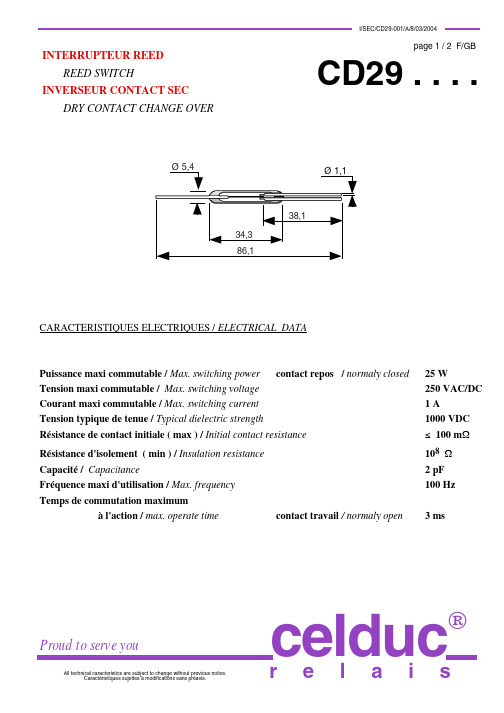
Référence ( Plage standard d'Ampères Tours de fermeture ) / Reference ( standard pull-in value )
CD295090 ( de 50 à 90 ATf / from 50 up to 90 AT )
Pour des applications particulières ( autres sensibilités, plage réduite, coupe, cambrage ), prière de nous consulter. For special applications ( others pull-in-range, reduced range, cutting out, bending ), please contact us.
Rhodium - 10 à +125°C - 40 à +125°C 50 g CEI 68-2-20
Bobine de test / Test coil : Ø ext. = 14,6 mm ; Ø int. = 5,7 mm ; Long. = 52,6 mm Fil utilisé / Electric wire: Ø = 0,09 mm ; Nombre de spires / Turns : 10 000 Resistance / Resistance : 800 Ω
Ø 5,4
38,1 34,3 86,1
CARACTERISTIQUES ELECTRIQUES / ELECTRICAL DATA
Puissance maxi commutable / Max. switching power contact repos / normaly closed Tension maxi commutable / Max. switching voltage Courant maxi commutable / Max. switching current Tension typique de tenue / Typical dielectric strength Résistance de contact initiale ( max ) / Initial contact resistance Résistance d'isolement ( min ) / Insulation resistance Capacité / Capacitance Fréquence maxi d'utilisation / Max. frequency Temps de commutation maximum à l'action / max. operate time
CD4013BMT,CD4013BMT,CD4013BNSR,CD4013BE,CD4013BM,CD4013BM96E4, 规格书,Datasheet 材料

Data sheet acquired from Harris Semiconductor SCHS023D − Revised April 2005The CD4013B types are supplied in 14-lead hermetic dual-in-line ceramic packa es (F3A suffix), 14-lead dual-in-line plastic packag es (E suffix), 14-lead small-outline packag es (M, MT, M96, and NSR suffixes), and 14-lead thin shrink small-outline packages (PW and PWR suffixes).*15105Copyright © 2005, Texas Instruments IncorporatedAddendum-Page 1PACKAGING INFORMATIONOrderable Device Status(1)Package Type PackageDrawingPins Package QtyEco Plan(2)Lead/Ball Finish MSL Peak Temp (3)Samples (Requires Login)89267AKB3T OBSOLETE CFP WR 14TBDCall TICall TICD4013BE ACTIVE PDIP N 1425Pb-Free (RoHS)CU NIPDAU N / A for Pkg Type CD4013BEE4ACTIVE PDIP N 1425Pb-Free (RoHS)CU NIPDAU N / A for Pkg TypeCD4013BF ACTIVE CDIP J 141TBD A42N / A for Pkg Type CD4013BF3A ACTIVE CDIP J 141TBD A42N / A for Pkg Type CD4013BF3AS2534OBSOLETE CDIP J 14TBD Call TI Call TI CD4013BK3OBSOLETE CFP WR 14TBDCall TICall TICD4013BM ACTIVE SOIC D 1450Green (RoHS & no Sb/Br)CU NIPDAU Level-1-260C-UNLIM CD4013BM96ACTIVE SOIC D 142500Green (RoHS & no Sb/Br)CU NIPDAU Level-1-260C-UNLIM CD4013BM96E4ACTIVE SOIC D 142500Green (RoHS & no Sb/Br)CU NIPDAU Level-1-260C-UNLIM CD4013BM96G4ACTIVE SOIC D 142500Green (RoHS & no Sb/Br)CU NIPDAU Level-1-260C-UNLIM CD4013BME4ACTIVE SOIC D 1450Green (RoHS & no Sb/Br)CU NIPDAU Level-1-260C-UNLIM CD4013BMG4ACTIVE SOIC D 1450Green (RoHS & no Sb/Br)CU NIPDAU Level-1-260C-UNLIM CD4013BMT ACTIVE SOIC D 14250Green (RoHS & no Sb/Br)CU NIPDAU Level-1-260C-UNLIM CD4013BMTE4ACTIVE SOIC D 14250Green (RoHS & no Sb/Br)CU NIPDAU Level-1-260C-UNLIM CD4013BMTG4ACTIVE SOIC D 14250Green (RoHS & no Sb/Br)CU NIPDAU Level-1-260C-UNLIM CD4013BNSR ACTIVE SO NS 142000Green (RoHS & no Sb/Br)CU NIPDAU Level-1-260C-UNLIM CD4013BNSRE4ACTIVE SO NS 142000Green (RoHS & no Sb/Br)CU NIPDAU Level-1-260C-UNLIM CD4013BNSRG4ACTIVE SO NS 142000Green (RoHS & no Sb/Br)CU NIPDAU Level-1-260C-UNLIM CD4013BPWACTIVETSSOPPW1490Green (RoHS & no Sb/Br)CU NIPDAU Level-1-260C-UNLIM芯天下--/Addendum-Page 2Orderable Device Status(1)Package Type PackageDrawingPins Package QtyEco Plan(2)Lead/Ball FinishMSL Peak Temp(3)Samples (Requires Login)CD4013BPWE4ACTIVE TSSOP PW 1490Green (RoHS & no Sb/Br)CU NIPDAU Level-1-260C-UNLIM CD4013BPWG4ACTIVE TSSOP PW 1490Green (RoHS & no Sb/Br)CU NIPDAU Level-1-260C-UNLIM CD4013BPWR ACTIVE TSSOP PW 142000Green (RoHS & no Sb/Br)CU NIPDAU Level-1-260C-UNLIM CD4013BPWRE4ACTIVE TSSOP PW 142000Green (RoHS & no Sb/Br)CU NIPDAU Level-1-260C-UNLIM CD4013BPWRG4ACTIVE TSSOP PW 142000Green (RoHS & no Sb/Br)CU NIPDAU Level-1-260C-UNLIMJM38510/05151BCA ACTIVE CDIP J 141TBD A42N / A for Pkg Type M38510/05151BCAACTIVECDIPJ141TBDA42N / A for Pkg Type(1)The marketing status values are defined as follows:ACTIVE: Product device recommended for new designs.LIFEBUY: TI has announced that the device will be discontinued, and a lifetime-buy period is in effect.NRND: Not recommended for new designs. Device is in production to support existing customers, but TI does not recommend using this part in a new design.PREVIEW: Device has been announced but is not in production. Samples may or may not be available.OBSOLETE: TI has discontinued the production of the device.(2)Eco Plan - The planned eco-friendly classification: Pb-Free (RoHS), Pb-Free (RoHS Exempt), or Green (RoHS & no Sb/Br) - please check /productcontent for the latest availability information and additional product content details.TBD: The Pb-Free/Green conversion plan has not been defined.Pb-Free (RoHS): TI's terms "Lead-Free" or "Pb-Free" mean semiconductor products that are compatible with the current RoHS requirements for all 6 substances, including the requirement that lead not exceed 0.1% by weight in homogeneous materials. Where designed to be soldered at high temperatures, TI Pb-Free products are suitable for use in specified lead-free processes.Pb-Free (RoHS Exempt): This component has a RoHS exemption for either 1) lead-based flip-chip solder bumps used between the die and package, or 2) lead-based die adhesive used between the die and leadframe. The component is otherwise considered Pb-Free (RoHS compatible) as defined above.Green (RoHS & no Sb/Br): TI defines "Green" to mean Pb-Free (RoHS compatible), and free of Bromine (Br) and Antimony (Sb) based flame retardants (Br or Sb do not exceed 0.1% by weight in homogeneous material)(3)MSL, Peak Temp. -- The Moisture Sensitivity Level rating according to the JEDEC industry standard classifications, and peak solder temperature.Important Information and Disclaimer:The information provided on this page represents TI's knowledge and belief as of the date that it is provided. TI bases its knowledge and belief on information provided by third parties, and makes no representation or warranty as to the accuracy of such information. Efforts are underway to better integrate information from third parties. TI has taken and continues to take reasonable steps to provide representative and accurate information but may not have conducted destructive testing or chemical analysis on incoming materials and chemicals.TI and TI suppliers consider certain information to be proprietary, and thus CAS numbers and other limited information may not be available for release.In no event shall TI's liability arising out of such information exceed the total purchase price of the TI part(s) at issue in this document sold by TI to Customer on an annual basis.芯天下--/OTHER QUALIFIED VERSIONS OF CD4013B, CD4013B-MIL :•Catalog: CD4013B•Military: CD4013B-MILNOTE: Qualified Version Definitions:•Catalog - TI's standard catalog product•Military - QML certified for Military and Defense ApplicationsAddendum-Page 3芯天下--/TAPE AND REEL INFORMATION*All dimensions are nominalDevicePackage Type Package Drawing Pins SPQReel Diameter (mm)Reel Width W1(mm)A0(mm)B0(mm)K0(mm)P1(mm)W (mm)Pin1Quadrant CD4013BM96SOIC D 142500330.016.4 6.59.0 2.18.016.0Q1CD4013BM96G4SOIC D 142500330.016.4 6.59.0 2.18.016.0Q1CD4013BMT SOIC D 14250330.016.4 6.59.0 2.18.016.0Q1CD4013BNSR SO NS 142000330.016.48.210.5 2.512.016.0Q1CD4013BPWRTSSOPPW142000330.012.46.95.61.68.012.0Q1*All dimensions are nominalDevice Package Type Package Drawing Pins SPQ Length(mm)Width(mm)Height(mm) CD4013BM96SOIC D142500367.0367.038.0 CD4013BM96G4SOIC D142500367.0367.038.0 CD4013BMT SOIC D1*******.0367.038.0 CD4013BNSR SO NS142000367.0367.038.0CD4013BPWR TSSOP PW142000367.0367.035.0IMPORTANT NOTICETexas Instruments Incorporated and its subsidiaries(TI)reserve the right to make corrections,enhancements,improvements and other changes to its semiconductor products and services per JESD46C and to discontinue any product or service per JESD48B.Buyers should obtain the latest relevant information before placing orders and should verify that such information is current and complete.All semiconductor products(also referred to herein as“components”)are sold subject to TI’s terms and conditions of sale supplied at the time of order acknowledgment.TI warrants performance of its components to the specifications applicable at the time of sale,in accordance with the warranty in TI’s terms and conditions of sale of semiconductor products.Testing and other quality control techniques are used to the extent TI deems necessary to support this warranty.Except where mandated by applicable law,testing of all parameters of each component is not necessarily performed.TI assumes no liability for applications assistance or the design of Buyers’products.Buyers are responsible for their products and applications using TI components.To minimize the risks associated with Buyers’products and applications,Buyers should provide adequate design and operating safeguards.TI does not warrant or represent that any license,either express or implied,is granted under any patent right,copyright,mask work right,or other intellectual property right relating to any combination,machine,or process in which TI components or services are rmation published by TI regarding third-party products or services does not constitute a license to use such products or services or a warranty or endorsement e of such information may require a license from a third party under the patents or other intellectual property of the third party,or a license from TI under the patents or other intellectual property of TI.Reproduction of significant portions of TI information in TI data books or data sheets is permissible only if reproduction is without alteration and is accompanied by all associated warranties,conditions,limitations,and notices.TI is not responsible or liable for such altered rmation of third parties may be subject to additional restrictions.Resale of TI components or services with statements different from or beyond the parameters stated by TI for that component or service voids all express and any implied warranties for the associated TI component or service and is an unfair and deceptive business practice. TI is not responsible or liable for any such statements.Buyer acknowledges and agrees that it is solely responsible for compliance with all legal,regulatory and safety-related requirements concerning its products,and any use of TI components in its applications,notwithstanding any applications-related information or support that may be provided by TI.Buyer represents and agrees that it has all the necessary expertise to create and implement safeguards which anticipate dangerous consequences of failures,monitor failures and their consequences,lessen the likelihood of failures that might cause harm and take appropriate remedial actions.Buyer will fully indemnify TI and its representatives against any damages arising out of the use of any TI components in safety-critical applications.In some cases,TI components may be promoted specifically to facilitate safety-related applications.With such components,TI’s goal is to help enable customers to design and create their own end-product solutions that meet applicable functional safety standards and requirements.Nonetheless,such components are subject to these terms.No TI components are authorized for use in FDA Class III(or similar life-critical medical equipment)unless authorized officers of the parties have executed a special agreement specifically governing such use.Only those TI components which TI has specifically designated as military grade or“enhanced plastic”are designed and intended for use in military/aerospace applications or environments.Buyer acknowledges and agrees that any military or aerospace use of TI components which have not been so designated is solely at the Buyer's risk,and that Buyer is solely responsible for compliance with all legal and regulatory requirements in connection with such use.TI has specifically designated certain components which meet ISO/TS16949requirements,mainly for automotive ponents which have not been so designated are neither designed nor intended for automotive use;and TI will not be responsible for any failure of such components to meet such requirements.Products ApplicationsAudio /audio Automotive and Transportation /automotiveAmplifiers Communications and Telecom /communicationsData Converters Computers and Peripherals /computersDLP®Products Consumer Electronics /consumer-appsDSP Energy and Lighting /energyClocks and Timers /clocks Industrial /industrialInterface Medical /medicalLogic Security /securityPower Mgmt Space,Avionics and Defense /space-avionics-defense Microcontrollers Video and Imaging /videoRFID OMAP Mobile Processors /omap TI E2E Community Wireless Connectivity /wirelessconnectivityMailing Address:Texas Instruments,Post Office Box655303,Dallas,Texas75265Copyright©2012,Texas Instruments Incorporated。
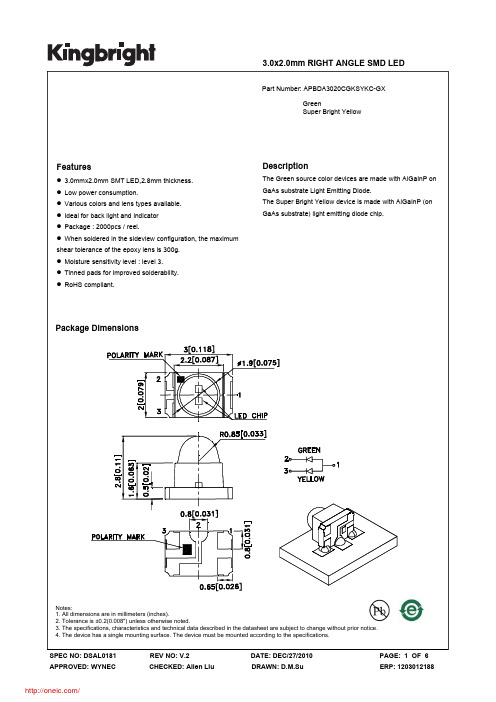
APBDA3020CGKSYKC-GX;中文规格书,Datasheet资料
DATE: DEC/27/2010 DRAWN: D.M.Su
PAGE: 5 OF 6 ERP: 1203012188
/
PACKING & LABEL SPECIFICATIONS
APBDA3020CGKSYKC-GX
SPEC NO: DSAL0181 APPROVED: WYNEC
3.0x2.0mm RIGHT ANGLE SMD LED
Part Number: APBDA3020CGKSYKC-GX Green Super Bright Yellow
Features
z 3.0mmx2.0mm SMT LED,2.8mm thickness. z Low power consumption. z Various colors and lens types available. z Ideal for back light and indicator z Package : 2000pcs / reel. z When soldered in the sideview configuration, the maximum shear tolerance of the epoxy lens is 300g. z Moisture sensitivity level : level 3. z Tinned pads for improved solderability. z RoHS compliant.
Notes: 1.Wavelength: +/-1nm. 2. Forward Voltage: +/-0.1V.
Absolute Maximum Ratings at TA=25°C
Parameter Power dissipation DC Forward Current Peak Forward Current [1] Reverse Voltage Operating Temperature Storage Temperature
CD-10 – CD-20 – CD-30 操作手册说明书
OPERATING MANUAL CD-10 – CD-20 – CD-30* non contractual picturesDear Customer,Thank you for purchasing one of the 3 Micromega CD players: CD-10, CD-20, CD-30. These players are mainly different by their audio characteristics. This manual is then common for the 3 models.This unit provides ease of use and sonics of the highest quality. Please pay close attention to this instruction manual, and read it fully before attempting to operate. It is designed to ensure you maximise your pleasure of CD player and familiarise you with its many unique functions .CHECKINGCheck that the carton has no damage. Should you have any doubt about its condition,The standby LED lightens up indicating that the unit is in standby mode.Press once the CD key of the remote control or the STANDBY key of the unit.If there is a disc, reading starts and its content is displayed. Otherwise it indicates:DISPLAY OFFYou can choose to minimize the display by pressing the key Display ▼ of the remote or by a long pressure on the DISC key of the unit.To come back to normal mode, press again on the MODE key. The display shows:In stop mode, after reading the content of the disc, the unit will display the name of the artist and the title of the albumBecause the display has 10 characters only, if the content is larger than this number, the display will scroll the text.DIGITAL OUPUTYou can activate the Digital output by executing a long pressure on the MODE key at any moment. This is necessary if you wish to use a separate Digital to Analog converter or if you wish to make a Digital recording. When activated, the display indicates:An optional DB9 female connector could be installed on the rear panel of CD player allows controlling it via RS232 interface. It accepts the following format:Baud Rate : 19200 Bauds Data bits : 8 Parity bit : None Stop bits : 1 Flow control : NoneYou will find complete instructions concerning this interface in the separate RS232 CD manual.AUDIS sarl. 13-15, rue du 8 mai 1945, ZA de la Haie Griselle, 94470 Boissy Saint Léger FRANCE TEL: +33 (0)1 4382 8860 - FAX: +33 (0)1 4382 6129 - INTERNET: TECHNICAL CHARACTERISTICS CD-XXDiscs supported ……………………………………………………………………………………..…… CD, CD-R, CD-RWAudio characteristicsBandwidth ( - 0.5dB )…………………………………………………………………………………….………… DC – 20Khz Linearity at –90dB………………………………………………………………………………………….……………. < 0.5dB Signal/Noise + THD…………………………………………………………………………………………….. < -96dB à1kHz Crosstalk………………………………………………………………………………..…………………….… >100dB at 1kHz D/A conversion type………………………………………………………………………………………………..………….. ∑∆ Oversampling (CD-10, CD-20)…………………………………………………………………………………..………… none Oversampling (CD-30)…………………………………………………………………………………….…………. 132.3 kHz Output impedance ……………………………………………………………………………………..………………….. 600 Ω Output level ………………………………………………………………………………………………………… 2Vrms / 0dBPowerPower consumption (Max) CD-10………………………………………………………………………………………... 20 W Power consumption (Max) CD-20, CD-30……………………………………………………………………………….. 40 WDimensions : ( L x P x H mm)………………………………………………………………………………... 430 x 250 x 70Weight CD-10……………………………………………………………………………………………….…….……….. 4.6 kg CD-20, CD-30…………………………………………………………………………………………….…….…. 5.6 kgWARRANTYThis warranty will start from the date of purchase of the Micromega product.Statutory warranty regulations apply in the country where the Micromega product was purchased. In case of complaints please contact the dealer who supplied your Micromega product.WARNING: Warranty will be nulled if the unit is not shipped back in its original packing or if the serial number has been modified or erased.Warranty Certificate Dealer's StampDate of PurchaseSerial Number。
PDC401NRV0R规格书(南京丙鼎)-12页word资料
技术文件技术文件名称:PDC401NRV0R技术文件编号:JS00429A版本:A/0共 13 页(包括封面)拟制审核标准化批准南京丙鼎电子有限公司1.显示指标22.极限参数23.直流特性24.光电特性35.管脚连接36.编码表37.外观要求38.质量保证99.LCD模块使用注意事项111.显示指标显示像素:4个七段8字+4个圆点+1个冒号可视区域:36.8(W)×16.3(H)毫米外型尺寸:最大60(W)×35.5(H)×10(T)毫米LCD类型:TN显示模式:反射式、正显示视角:6:00点钟控制/驱动芯片:KS0065温度范围:工作-30℃~+70℃存储- 40℃~+75℃模块工作电压:5V.背光源工作电压:5V2.极限参数2.1电压及温度极限参数注意(1)T a= 0°C :最大50Hr(2)T a≤40°C :最大90%RHT a≥40°C :绝对湿度必须低于40°C、90%RH下的湿度。
3.直流特性4.光电特性4.1 TN屏体光电特性5.管脚连接6.编码表7.外观要求7.1检查项目7.2 判定标准8.质量保证8.1 测试条件8.1.1 温度和湿度(环境温度)温度:20±5℃湿度:65±5%RH8.1.2 测试频率单循环注意1:常温下恢复4小时注意2:观察时无露水凝结注意3:各项试验后,在规定测试条件下模块能正常工作。
8.1.4 试验条件低温运行:-30℃持续时间:4h高温运行:+70℃持续时间:4h高温存贮:+75℃持续时间:4h恢复时间:2h低温存贮:-40℃持续时间:4h恢复时间:2h恒定湿热:+35℃湿度:93%+2%/-3%持续时间48h高低温冲击:跌落:整机做跌落试验,按照整机跌落试验的条件进行。
8.2 试验内容LCD测试:测试时,笔划有无多缺、颜色是否均匀、对比度是否良好。
环境测试:如果测试条件不允许,可以考虑将以下所有“箱内在线测试”改为“取出后立即测试”。
CD4013中文资料及应用
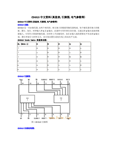
CD4013中文资料(真值表,引脚图,电气参数等)CD4013中文资料(真值表,引脚图,电气参数等)CD4013功能:CD4013是一双D触发器,由两个相同的、相互独立的数据型触发器构成。
每个触发器有独立的数据、置位、复位、时钟输入和Q及Q输出,此器件可用作移位寄存器,且通过将Q输出连接到数据输入,可用作计算器和触发器。
在时钟上升沿触发时,加在D输入端的逻辑电平传送到Q输出端。
置位和复位与时钟无关,而分别由置位或复位线上的高电平完成。
CD4013 Truth Table 真值表功能:CL (Note 1) D R S Q Q↑0 0 0 0 1↑ 1 0 0 1 0↓x 0 0 Q Qx x 1 0 0 1x x 0 1 1 0x x 1 1 1 1CD4013引脚图:图1CD4013引脚图CD4013内部结构图:图2CD4013内部电路图图3 CD4013逻辑图CD4013电气参数:Absolute Maximum Ratings 绝对最大额定值:DC Supply Voltage 直流供电电压 (VDD) -0.5 VDC to +18 VDC Input Voltage输入电压 (VIN) -0.5 VDC to VDD +0.5 VDC Storage Temperature Range储存温度范围 (TS) -65℃ to +150℃Recommended Operating Conditions 建议操作条件:DC Electrical Characteristics 直流电气特性:AC Electrical Characteristics 交流电气特性:图4 切换时间波形CD4013应用电路:图5(左)和图(右)中的CD4013是CMOS双D触发器,这类电路置位和复位信号是高电平有效,由于开关闭合时电容可视为短路而产生高电平,使RD=1,Q=0;若将此信号加到SD,则SD=1,Q=1;置位、复位过后,电容充电而使RD(SD)变为0,电路可进入计数状态。
CD0中文手册
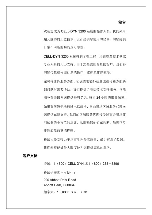
激光器标签,后面板
序列号标签,后面板 CE 标签,后面板
警告:为120伏电压进行的设
置
如需使用其他线路电压进行操作时,请参阅操作手册中的详细说明。
PN 9230003
电压标签,后面板
小心:除非采取了相应的保护措施,否则不要处理溶液容器。
有关安装程序请参阅操作人员手册。
PN 9230334
溶液容器标签,后面板
注意:在本手册中这些标签多用图形形式表示。
如何使用本手册
概述
本操作手册对使用与维护CELL-DYN 3200系统进行了完整的说明。
本手册的目的是为了满足下列需要:从对操作过程进行逐一说明,到辅件编号的列表。
在您学习使用本系统时,本手册会为您提供很大的帮助,在以后的使用过程中也会为您提供实质性的参考。
1级激光器产品
PN 9230702。
G3TB I O Solid State Relay商品说明书

G 3T BI/O SSR Used as Interface between Logic Circuitry and Load•A variety of AC/DC input and output modules are classified by color.•Operation can be monitored easily by LED indicator.•Dielectric strength of 4,000 V between input and output terminals.•Lineup includes models with UL and CSA certification (model numbers ending in “-US”).■List of Models•Input Modules•Output Modules■Ratings•Input Module Input•Output Module InputOutputRoHS CompliantIsolation Indicator Logic level Supply voltage Logic level Supply currentRated input voltage Model Minimun packing unit PhotocouplerY es4 to 32 VDC25 mA100 to 240 VACG3TB-IAZR02P 20 pcs5 to 24 VDCG3TB-IDZR02PIsolationZero cross functionIndicator Rated output voltageRated input voltageModel Minimun packing unitPhotocouplerY es Y es 3 A at 100 to 240 VAC5 to 24 VDC G3TB-OA203PZ 20 pcsNo 4 to 24 VDC G3TB-OA203PZM NoY es 5 to 24 VDC G3TB-OA203PL No 4 to 24 VDC G3TB-OA203PLM −Y es 3 A at 5 to 48 VDC 5 to 24 VDC G3TB-ODX03P No 4 to 24 VDC G3TB-ODX03PM Y es 1.5 A at 48 to 200 VDC5 to 24 VDC G3TB-OD201P No4 to 24 VDCG3TB-OD201PMItemRated voltageOperating voltage Input current Voltage levelModelMust operate voltage Must release voltage G3TB-IAZR02P 100 to 240 VAC 80 to 264 VAC 5 mA max.80 VAC max.10 VAC min.G3TB-IDZR02P5 to 24 VDC4 to 32 VDC5 mA max.4 VDC max. 1 VDC min.ItemModelRated voltage Operating voltage Input currentVoltage levelMust operate voltage Must release voltage G3TB-OA203PZ 5 to 24 VDC 4 to 32 VDC 5 mA max.4 VDC max. 1 VDC min.G3TB-OA203PZM 4 to 24 VDC 3 to 32 VDC 3 VDC max.G3TB-OA203PL 5 to 24 VDC 4 to 32 VDC 4 VDC max.G3TB-OA203PLM 4 to 24 VDC 3 to 32 VDC 3 VDC max.G3TB-ODX03P 5 to 24 VDC 4 to 32 VDC 4 VDC max.G3TB-ODX03PM 4 to 24 VDC 3 to 32 VDC 3 VDC max.G3TB-OD201P 5 to 24 VDC 4 to 32 VDC 4 VDC max.G3TB-OD201PM4 to 24 VDC3 to 32 VDC3 VDC max.ItemApplicable loadModelRated load voltage Load voltage range Load current Inrush current G3TB-OA203PZ 100 to 240 VAC75 to 264 VAC0.05 to 3 A*1, 245 A(60 Hz, 1 cycle)*1.The minimum current value is measured at 10°C min.*2.The applicable output load current variesdepending on the ambient temperature.Refer to reference data the "Load Current vs. Ambient Temperature" rating characteristic for details.G3TB-OA203PZM G3TB-OA203PL G3TB-OA203PLM G3TB-ODX03P 5 to 48 VDC 4 to 60 VDC 0.01 to 3 A *1, 218 A (10 ms)G3TB-ODX03PM G3TB-OD201P 48 to 200 VDC40 to 200 VDC0.01 to 1.5 A *1, 29 A (10 ms)G3TB-OD201PMRefer to "Solid State Relays Common Precautions".OutputItemModel Logic levelsupply voltageOutputbreakdownvoltage Output current G3TB-IAZR02P4 to 32 VDC32 VDC max.25 mA max.G3TB-IDZR02P 4 to 32 VDCG3TB I/O Solid State RelayG 3 T B ■Characteristics•Input Module■Engineering Data•Load Current vs. Ambient Temperature Characteristics•One Cycle Surge Current: Non-repetitive Non-repetitive (Keep the inrush current to half the rated value if it occurs repetitively.) ModelItemG3TB-IAZR02P G3TB-IDZR02POperate time20 ms max. 1 ms max.Release time20 ms max. 1 ms max.Output ONvoltage drop0.4 V max.Leakage current100 μA max.Insulationresistance100 MΩ min. (at 500 VDC)Dielectricstrength4,000 VAC, 50/60 Hz for 1 min betweeninput and outputVibrationresistance10 to 55 to 10 Hz,0.75-mm single amplitude(1.5mm double amplitude)Shock resistance1,000 m/s2Storagetemperature–30°C to 100°C(with no icing or condensation)Ambientoperatingtemperature–30°C to 80°C(with no icing or condensation)Ambientoperatinghumidity45% to 85%RHWeight Approx. 22 gG3TB-OA203PZ G3TB-OA203PLMG3TB-OA203PZMG3TB-OA203PLG3TB-ODX03PG3TB-ODX03PMG3TB-OD201PG3TB-OD201PMG3TB-OA203PZ G3TB-OA203PLG3TB-OA203PZM G3TB-OA203PLMG3TB-ODX03PG3TB-ODX03PMG3TB-OD201PG3TB-OD201PM•Output ModuleModelItemG3TB-OA203PZG3TB-OA203PZMG3TB-OA203PLG3TB-OA203PLMG3TB -ODX03PG3TB-ODX03PMG3TB -OD201PG3TB-OD201PMOperate time1/2 of load power sourcecycle + 1 ms max.1 ms max.0.5 ms max.Release time1/2 of load power source cycle + 1 ms max. 2 ms max.Output ONvoltage drop1.6 V (RMS) max. 1.6 V max.2.5 V max.Leakage current 5 mA max. (at 200 VAC) 1 mA max.Insulationresistance100 MΩ min. (at 500 VDC)Dielectricstrength4,000 VAC, 50/60 Hz for 1 min between input and outputVibrationresistance10 to 55 to 10 Hz, 0.75-mm single amplitude (1.5mm double amplitude)Shock resistance1,000 m/s2Storagetemperature–30°C to 100°C (with no icing or condensation)Ambientoperatingtemperature–30°C to 80°C (with no icing or condensation)Minimum load current: 10 to 80°CRefer to the Load Current - Ambient Temperature Rating for the minimum load current.Ambientoperatinghumidity45% to 85%RHWeightApprox. 32 g-Am b ient temper a t u re (°C)Loadcurrent(A)-Am b ient temper a t u re (°C)Loadcurrent(A)-Am b ient temper a t u re (°C)Loadcurrent(A)504030201010 30 50 100 200 500 1,000 5,000Energized time (m s)Inrushcurrent(A.Peak)3028262422201816141210864210 30 50 100 300 500 1,000 3,000Energized time (m s)Inrushcurrent(A.Peak)15141312111098765432110 30 50 100 300 500 1,000 3,000Energized time (m s)Inrushcurrent(A.Peak)G3TBI/O Solid State RelayG 3T B■Circuit Configuration•Example of Logic Output Circuit ■Dimensions(Unit: mm)T ypeModelCase colorIndicatorCircuitAC input G3TB-IAZR02P Y ellow Y esDC input G3TB-IDZR02P White Y esAC outputG3TB-OA203PZ G3TB-OA203PLBlackY esG3TB-OA203PZM G3TB-OA203PLM NoDC outputG3TB-ODX03P G3TB-OD201PRedY esG3TB-ODX03PM G3TB-OD201PMNoExample 1. G3TB-IExample 2. G3TB-IR e c t i f i c a t i o n c i r c u i tA m p l i f i c a t i o n c i r c u i tC o n s t a n t -c u r r e n t c i r c u i tA m p l i f i c a t i o n c i r c u i t C o n s t a n t -c u r r e n t c i r c u i tC o n s t a n t -c u r r e n t c i r c u i tD r i v e c i r c u i tZ e r o -c r o s s c i r c u i t R e c t i f i c a t i o n c i r c u i t C o n s t a n t -c u r r e n t c i r c u i tA m p l i f i c a t i o n c i r c u i tS e q u e n t i a l c i r c u i t o r C P ULogic circu itryNote: AC- a nd DC-inp u t ver s ion s a re a v a il able.S W 4 to 32 VDC+34−53.3K(+)(−)Ex a mple: Rel a y with bu ilt-in inr us h abs orption diodeNote: AC- a nd DC-inp u t ver s ion s a re a va il ab le.S W 4 to 32 VDC+34−53.3K(+)(−)L o a dsExtern a l inp u tO u tp u t L o a dL o g i c c i r c u i t1+3+45−2−VccExtern a l inp u t O u tp u tL o a dL o g i c c i r c u i t1~3+45−2~VccInput SSR G3TB-IPCB Dimensions (Bottom View)Terminal Arrangement (Bottom View)G3TB I/O Solid State RelayG 3 T B ■Safety Precautions●Please refer to “Solid State Relays Common Precautions” for correct use.sExtern a l AC o u tp u t Logic inp u tLoad1~Z2Z13+4−2~Extern a l DC o u tp u t Logic inp u tLoad1+3+4−2−Output SSRG3TB-IPCB Dimensions (Bottom View)Terminal Arrangement (Bottom View)Note.Connect the varistor tothe Z1 or Z2.Note.Connect the diode inparallel with the load.PLC or logiccirc u itry AC eq u ipment100 to 240 VACG3TB-IAZR02P Y ellowAC inp u t mod u le5 to 24 VDCDC eq u ipment 5 to 24 VDCG3TB-IDZR02P WhiteDC inp u t mod u le5 to 24 VDCAC eq u ipmentDC eq u ipment100 to 240 VAC 3 AG3TB-OA203PZG3TB-OA203PZMG3TB-OA203PLG3TB-OA203PLMBl a ckAC o u tp u t mod u le5 to 24 VDC (4 to 24 VDC)4 to 60 VDC/40 to 200 VDC 3 A* With 1.5-A o u tp u t.G3TB-ODX03PG3TB-ODX03PM*G3TB-OD201P*G3TB-OD201PMRedDC o u tp u t mod u le5 to 24 VDC (4 to 24 VDC)•SSR for I/O classification by the color is as follows:Precautions for Correct Use5 mm min.O u tp u t mod u le•When mounting more than one outputmodule, make a distance of 5 mmminimum between adjacent SSRs. Upto 16-point, 3-A load switching ispossible.G3TBI/O Solid State RelayG 3T BCat. No. K077-E1-051014(0207)(O)OMRON CorporationElectronic and Mechanical Components CompanyContact: /ecbNote: Do not use this document to operate the Unit.• Application examples provided in this document are for reference only. In actual applications, confirm equipment functions and safety before using the product.• Consult your OMRON representative before using the product under conditions which are not described in the manual or applying the product to nuclear control systems, railroad systems, aviation systems, vehicles, combustion systems, medical equipment, amusement machines, safety equipment, and other systems or equipment that may have a serious infl uence on l ives and property if used improperl y. Make sure that the ratings and performance characteristics of the product provide a margin of safety for the system or equipment, and be sure to provide the system or equipment with double safety mechanisms.。
cd4069中文资料_数据手册_参数

NS 14 2000 Green (RoHS & no Sb/Br)
CU NIPDAU
Level-1-260C-UNLIM -55 to 125
NS 14 2000 Green (RoHS & no Sb/Br)
CU NIPDAU
Level-1-260C-UNLIM -55 to 125
PW
14
90 Green (RoHS
(5) Multiple Device Markings will be inside parentheses. Only one Device Marking contained in parentheses and separated by a "~" will appear on a device. If a line is indented then it is a continuation of the previous line and the two combined represent the entire Device Marking for that device.
ACTIVE TSSOP
ACTIVE
CDIP
D
14
50 Green (RoHS
& no Sb/Br)
CU NIPDAU
Level-1-260C-UNLIM -55 to 125
D
14 2500 Green (RoHS CU NIPDAU | CU SN Level-1-260C-UNLIM -55 to 125
Copyright 2003, Texas Instruments Incorporated
PACKAGE OPTION ADDENDUM
D300RW中文资料
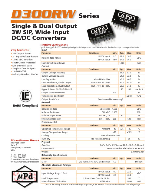
Key Features:• 3W Output Power• 2:1 Input Voltage Range • 1,500 VDC Isolation • Short Circuit Protected • Miniature SIP Case • Single & Dual Outputs • 1.0 MH MTBF• Industry Standard Pin-OutD300RWSingle & Dual Output 3W SIP , Wide Input DC/DC Con v ert e rsSeriesInputParameterConditionsMin.Typ.Max.Units Input Voltage Range 12 VDC Input 9.012.018.0VDC 24 VDC Input18.024.036.0Short Circuit Input Power1,500mW OutputParameterConditionsMin.Typ.Max.Units Output Voltage Accuracy ±1.0±3.0%Output Voltage Balance ±1.0±2.0%Line RegulationVin = Min to Max ±0.2±0.5%Load Regulation , Single Output Iout = 10% to 100%±0.5±0.75%Load Regulation , Dual Output Iout = 10% to 100%±0.5±1.0%Ripple & Noise (20 MHz) (Note 1)50100mV P - P Output Power Protection 120%Temperature Coeffi cient ±0.03%/°COutput Short CircuitContinuous (Autorecovery)GeneralParameter ConditionsMin.Typ.Max.Units Isolation Voltage 60 Seconds 1,500VDC Isolation Resistance 500 VDC 1,000M ΩIsolation Capacitance 100 kHz, 1V 80pF Switching FrequencyIout = 100%200500kHz EnvironmentalParameterConditionsMin.Typ.Max.Units Operating Temperature Range Ambient-40+25+85°C Storage Temperature Range -50+125°CCooling Free Air ConvectionHumidityRH, Non-condensing95%PhysicalCase Size 0.87 x 0.47 x 0.37 Inches (22.0 x 12.0 x 9.50 mm)Case Material Non-Conductive Black Plastic (UL94-V0)Weight0.20 Oz (6.0g)Reliability Specifi cationsParameter ConditionsMin.Typ.Max.Units MTBFMIL HDBK 217F , 25°C, Gnd Benign1.0MHours Absolute Maximum RatingsParameterConditionsMin.Typ.Max.Units Input Voltage Surge (1 Sec)12 VDC Input -0.722.0VDC 24 VDC Input-0.740.0Lead Temperature 1.5 mm From Case For 10 Sec300°C Internal Power DissipationAll Models1,800mWCaution: Exceeding Absolute Maximum Ratings may damage the module. These are not continuous operating ratings.Electrical Specifi cationsSpecifi cations typical @ +25°C, nominal input voltage & rated output current, unless otherwise noted. Specifi cations subject to change without notice.MicroPower Direct292 Page StreetSuite DStoughton, MA 02072USAT: (781) 344-8226F: (781) 344-8481E: sales@ W: RoHS CompliantModel Selection GuideMechanical DimensionsModel Number InputOutputEffi ciency(%, Typ)Fuse RatingSlow-Blow (mA)Voltage (VDC)Current (mA)Voltage (VDC)Current (mA, Max)Current(mA, Min)Nominal Range Full-Load No-Load D301RW 129.0 - 18.032022 5.0600.060.078700D302RW 129.0 - 18.0316229.0333.033.079700D303RW 129.0 - 18.03122212.0250.025.080700D304RW 129.0 - 18.03122215.0200.020.080700D305RW 129.0 - 18.032022±5.0±300.0±30.078700D306RW 129.0 - 18.031622±9.0±167.0±17.079700D307RW 129.0 - 18.031222±12.0±125.0±13.080700D308RW 129.0 - 18.031222±15.0±100.0±10.080700D311RW 2418.0 - 36.016010 5.0600.060.078350D312RW 2418.0 - 36.0158109.0333.033.079350D313RW 2418.0 - 36.01561012.0250.025.080350D314RW 2418.0 - 36.01541015.0200.020.081350D315RW 2418.0 - 36.016010±5.0±300.0±30.078350D316RW 2418.0 - 36.015810±9.0±167.0±17.079350D317RW 2418.0 - 36.01568±12.0±125.0±13.080350D318RW2418.0 - 36.01548±15.0±100.0±10.081350Pin Single Dual 1-Vin -Vin 2+Vin +Vin 3Remote ON/OFF 5NF NF 6+Vout +Vout 7-Vout Common 8CS -Vout NF = No FunctionPin ConnectionsNotes:1. When measuring output ripple, it is recommended that an external ceramic capaci-tor (approx. 1 µF to 10 µF) be placed from the +Vout pin to the -Vout pin for single output units and from each output to common for dual output units.2. T hese units should not be operated with a load under 10% of full load. Operation at no-load may cause damage to the unit.3. These converters are specifi ed for operation without external components. However, in some applications the addition of input/output capacitors will enhance stability and reduce output ripple.Recommended capaci-tor values are given in the table at right. Usingsimple LC fi lter networkson the input/output will provide further improve-ment. This only requires the addition of smallinductors to the input/output fi lter circuits. Recommended values are 4.7 µH to 120 µH for an input inductor and 2.2 µH to 10 µH for an output inductor. Output ripple on single output units maybe further enhanced by using the CS termi-nal (single output units operated at 50% load or below should use this function). A low ESR capacitor is connected betweenthe CS pin and the -Vout pin (the anode of the capacitor is connected to the -Vout pin). Recommended capacitor values are given in the table above. If not used, the CS pin should be left open.4. D ual output units may be connected to provide a 10V, 18V, 24V or 30 VDC output. To do this, connect the load across the +Vout and -Vout outputs and fl oat the output common.5. The remote on/off control pin is referencedto the -Vin pin (pin 1). Input current to thepin should be between 5 - 10 mA with a maximum of 20 mA.6. It is recommended that a fuse be used on the input of a power supply for protec-tion. See the Model Selection table above for the correct rating.Vin InputCapacitorVout Output Capacitor0 - 70ºC (Electrolitic)-40 - 85ºC (Tantalum)12 VDC 100 µF 5 VDC 100 µF 47 µF 24 VDC 10 - 47 µF 9 VDC100 µF 47 µF 12 VDC 100 µF 47 µF15 VDC 100 µF 47 µF Output Voltage 5V 9V 12V 15VCS 47 µF - 100 µF 22 µF - 47 µF Min Max On <0.6 VDC to Open Circuit Off 2.7 VDC 15.0 VDC Mechanical Notes:• All dimensions are typical in inch e s (mm)• Tolerance x.xx = ±0.01 (±0.25)MicroPower Direct292 Page Street Ste D Stoughton, MA 02072 • TEL: (781) 344-8226 • FAX: (781) 344-8481 • E-Mail: sales@Output Max Cap Load 5.0 VDC 2,200 µF 9.0 VDC 1,000 µF 12.0 VDC 820 µF 15.0 VDC 680 µF ±5.0 VDC ±560 µF ±9.0 VDC ±470 µF ±12.0 VDC ±330 µF ±15.0 VDC±220 µFCapacitive LoadDerating Curve。
CDSOD323-T03中文资料

ID
5
5
5
5
2
2
1
1
µA
CJ
3
pF
Notes: 1. Part numbers with suffix “C” indicate bidirectional device, i.e. CDSOD323-T05C. 2. For bidirectional devices only, the electrical specifications apply in both directions.
VF
24.0
24.0
29.0
29.0
43.0
43.0
V
VC
31.8 V 31.8 V 45.0 V 45.0 V 56.0 V 56.0 V
V
@ 10 A @ 10 A @ 8 A @ 8 A @ 6 A @ 6 A
ID
1
µA
CJ
3
pF
Notes: 1. Part numbers with suffix “C” indicate bidirectional device, i.e. CDSOD323-T05C. 2. For bidirectional devices only, the electrical specifications apply in both directions.
元器件交易网
CDSOD323-TxxC – TVS Diode Array Series
Electrical & Thermal Characteristics (@ TA = 25 °C Unless Otherwise Noted)
Parameter
Symbol
NJW0302G;NJW0281G;中文规格书,Datasheet资料

NJW0281G (NPN)NJW0302G (PNP)Preferred Devices Complementary NPN-PNP Power Bipolar TransistorsThese complementary devices are lower power versions of the popular NJW3281G and NJW1302G audio output transistors. With superior gain linearity and safe operating area performance, these transistors are ideal for high fidelity audio amplifier output stages and other linear applications.Features•ăExceptional Safe Operating Area•ăNPN/PNP Gain Matching within 10% from 50 mA to 3 A•ăExcellent Gain Linearity•ăHigh BVCEO•ăHigh Frequency•ăThese are Pb-Free DevicesBenefits•ăReliable Performance at Higher Powers•ăSymmetrical Characteristics in Complementary Configurations •ăAccurate Reproduction of Input Signal•ăGreater Dynamic Range•ăHigh Amplifier BandwithApplications•ăHigh-End Consumer Audio Products♦ăHome Amplifiers♦ăHome Receivers•ăProfessional Audio Amplifiers♦ăTheater and Stadium Sound Systems♦ăPublic Address Systems (PAs)MAXIMUM RATINGSRating Symbol Value UnitCollector-Emitter Voltage V CEO250Vdc Collector-Base Voltage V CBO250Vdc Emitter-Base Voltage V EBO 5.0Vdc Collector-Emitter Voltage - 1.5 V V CEX250VdcCollector Current - Continuous-Peak (Note 1)I C1530AdcBase Current - Continuous I B1.5AdcTotal Power Dissipation @ T C = 25°C P D150WattsOperating and Storage Junction Temperature Range T J, T stg-65 to+150°CStresses exceeding Maximum Ratings may damage the device. Maximum Ratings are stress ratings only. Functional operation above the Recommended Operating Conditions is not implied. Extended exposure to stresses above the Recommended Operating Conditions may affect device reliability.1.Pulse Test: Pulse Width = 5.0 ms, Duty Cycle < 10%.15 AMPERES COMPLEMENTARY SILICON POWER TRANSISTORS250 VOLTS, 150 WATTSDevice Package ShippingORDERING INFORMATIONTO-3PCASE 340ABMARKINGDIAGRAMPreferred devices are recommended choices for future use and best overall value.NJW0302G TO-3P(Pb-Free)30 Units/Rail NJW0281G TO-3P(Pb-Free)30 Units/Railxxxx= 0281 or 0302G= Pb-Free PackageA= Assembly LocationY= YearWW= Work WeekNJWxxxGAYWWTHERMAL CHARACTERISTICSCharacteristicSymbol Value Unit Thermal Resistance, Junction-to-CaseR θJC0.83°C/WELECTRICAL CHARACTERISTICS (T C = 25°C unless otherwise noted)CharacteristicSymbolMinMaxUnitOFF CHARACTERISTICSCollector-Emitter Sustaining Voltage (I C = 30 mA, I B = 0)V CEO(sus)250-V Collector Cutoff Current (V CB = 250 V, I E = 0)I CBO -10m A Emitter Cutoff Current (V EB = 5.0 V, I C = 0)I EBO- 5.0m AON CHARACTERISTICS DC Current Gain(I C = 0.5 A, V CE = 5.0 V)(I C = 1.0 A, V CE = 5.0 V)(I C = 3.0 A, V CE = 5.0 V)h FE757575150150150-Collector-Emitter Saturation Voltage (I C = 5.0 A, I B = 0.5 A)V CE(sat)- 1.0V Base-Emitter On Voltage (I C = 5.0 A, V CE = 5.0 V)V BE(on)- 1.2V DYNAMIC CHARACTERISTICSCurrent-Gain - Bandwidth Product(I C = 1.0 A, V CE = 5.0 V, f test = 1.0 MHz)f T 30-MHz Output Capacitance(V CB = 10 V, I E = 0, f test = 1.0 MHz)C ob-400pF160T C , CASE TEMPERATURE (°C)40601001201608014020Figure 1. Power Derating 020406080100140120P D , P O W E R D I S S I P A T I O N (W)0.010.11101001101001000V CE , COLLECTOR-EMITTER VOLTAGE (V)I C , C O L L E C T O R C U R R E N T (A )Figure 2. Safe Operating Area00.20.40.60.811.21.40.010.1110100I C , COLLECTOR CURRENT (A)Figure 3. NJW0281G DC Current GainFigure 4. NJW0302G DC Current Gainh F E , D C C U R R E N T G A I NI C , COLLECTOR CURRENT (A)Figure 5. NJW0281G Base-Emitter Voltage I C , COLLECTOR CURRENT (A)0.010.1110100Figure 6. NJW0302G Base-Emitter VoltageV B E (o n ), B A S E -E M I T T E R V O L T A G E (V )I C , COLLECTOR CURRENT (A)V B E (o n ), B A S E -E M I T T E R V O L T A G E (V )h F E , D C C U R R E N T G A I N0.050.111050-0.10.40.91.41.92.40.050.111050Figure 7. NJW0281G Saturation Voltage 0.010.11100.010.1110100I C , COLLECTOR CURRENT (A)V C E (s a t ), C O L L E C T O R -E M I T T E R S A T U R A T I O N V O L T A G E (V)0.010.11100.010.1110100Figure 8. NJW0302G Saturation VoltageI C , COLLECTOR CURRENT (A)V C E (s a t ), C O L L E C T O R -E M I T T E R S A T U R A T I O N V O L T A G E (V )0102030405060700.010.1110Figure 9. NJW0281G Current Gain BandwidthProduct I C , COLLECTOR CURRENT (A)f T , C U R R E N T G A I N B A N D W I D T H P R O D U C T (M H z )Figure 10. NJW0302G Current Gain BandwidthProductI C , COLLECTOR CURRENT (A)f T , C U R R E N T G A I N B A N D W I D T H P R O D U C T (M H z )01020304050600.010.1110PACKAGE DIMENSIONSTO-3P-3LD CASE 340AB-01ISSUE ADIM A MIN NOM MAX MILLIMETERS 19.7019.9020.10B 15.4015.6015.80C 4.60 4.80 5.00D 0.80 1.00 1.20E 1.45 1.50 1.65G 5.45 BSC H 1.20 1.40 1.60J 0.550.600.75K 19.8020.0020.20L 18.5018.7018.90U 5.00 REF P 3.30 3.50 3.70Q 3.10 3.20 3.50W2.803.00 3.20NOTES:1.DIMENSIONING AND TOLERANCING PER ASME Y14.5M, 1994.2.CONTROLLING DIMENSION: MILLIMETERS3.DIMENSION b APPLIES TO PLATED TERMINAL AND IS MEASURED BETWEEN 0.15 AND 0.30mm FROM THE TERMINAL TIP.4.DIMENSION A AND B DO NOT INCLUDE MOLD FLASH, PROTRUSIONS, OR GATE BURRS.F 1.80 2.00 2.20SEATING PLANEFUON Semiconductor and are registered trademarks of Semiconductor Components Industries, LLC (SCILLC). SCILLC reserves the right to make changes without further notice to any products herein. SCILLC makes no warranty, representation or guarantee regarding the suitability of its products for any particular purpose, nor does SCILLC assume any liability arising out of the application or use of any product or circuit, and specifically disclaims any and all liability, including without limitation special, consequential or incidental damages.“Typical” parameters which may be provided in SCILLC data sheets and/or specifications can and do vary in different applications and actual performance may vary over time. All operating parameters, including “Typicals” must be validated for each customer application by customer's technical experts. SCILLC does not convey any license under its patent rights nor the rights of others. SCILLC products are not designed, intended, or authorized for use as components in systems intended for surgical implant into the body, or other applications intended to support or sustain life, or for any other application in which the failure of the SCILLC product could create a situation where personal injury or death may occur. Should Buyer purchase or use SCILLC products for any such unintended or unauthorized application, Buyer shall indemnify and hold SCILLC and its officers, employees, subsidiaries, affiliates,and distributors harmless against all claims, costs, damages, and expenses, and reasonable attorney fees arising out of, directly or indirectly, any claim of personal injury or death associated with such unintended or unauthorized use, even if such claim alleges that SCILLC was negligent regarding the design or manufacture of the part. SCILLC is an Equal Opportunity/Affirmative Action Employer. This literature is subject to all applicable copyright laws and is not for resale in any manner.PUBLICATION ORDERING INFORMATION分销商库存信息:ONSEMINJW0302G NJW0281G。
德力西电气 CDBA产品样本 产品说明书

CDBA系列物联网小型断路器CDBALE系列物联网小型漏电断路器CDGA-4G物联网网关物联网云平台作为中国改革开放第一代优秀民营企业,德力西集团历经近四十载的不懈奋斗,在广大客户和合作伙伴的长期信赖与支持下,于2007年与全球500强施耐德电气强强携手,合资成立德力西电气有限公司(简称“德力西电气”)。
德力西电气业务覆盖配电电气、工业控制自动化、家居电气三大领域,致力于以高性价比、高效率和高质量的产品与服务,为全球新兴市场客户创造舒适、美观、安全、智能的居家用电环境和专业、安全、可靠、高效的工业自动化用电环境,探索中国低压电气行业企业发展新模式。
我们以客户和合作伙伴的利益为出发点,坚持以技术创新、质量保障、五星服务、品牌驱动为经营理念,打造电气全产业链新生态。
我们拥有700多家一级代理商、60000多家线下门店、多个线上销售平台和合作伙伴、5个研发中心、3个国家级实验室、3大自动化工业生产基地、五星级客户支持服务团队、17个国内物流中心以及数十个运输合作伙伴、1个国际物流中心和在发展中国家的4大业务合作伙伴,以及持续一致的全方位品牌建设及宣传,致力在全球范围内创造最佳客户体验闭环。
我们秉承“客户第一、合作、敏捷、创新、超越”的价值观,全心全意服务于我们的客户,同时携手合作伙伴建立具有统一价值观的社会责任生态圈,通过“德基金”全情回馈社会,用实际行动践行企业社会责任,持续打造具有德力西电气特色的“一老一小传统文化”的企业公益品牌,构建一个有温度的国际化低压电气领军企业 。
19技术参数主要特性执行标准GB 4943.1-2011额定电压AC230V通信方式上行:4G网络下行:RS-485安装方式TH35-7.5导轨工作环境温度-35℃~+70℃储存环境温度-40℃~+85℃技术参数主要特性执行标准GB/T10963.1;NB/T42149额定频率50/60Hz 极数1P 、2P 、3P 、4P 额定电压AC230V (1P/2P ),AC400V (3P/4P )额定电流6,10,16,20,25,32,40,50,63A 瞬时脱扣特性C,D 分断能力6kA 机械寿命10000次电气寿命4000次安装方式TH35-7.5导轨接线能力25mm ²最大接线扭矩2.5N·m 电流测量精度0.5级电压测量精度0.5级功率测量精度0.5级过电压动作整定值默认275±10V 延时3s 脱扣,可远程整定参数过电压动作恢复值默认1.1Ue ,延时30±5s ,可远程整定参数欠电压保护整定值默认160±10V 延时3s 脱扣,可远程整定参数欠电压动作恢复值默认0.85Ue ,延时30±5s ,可远程整定参数分合闸方式手动远程遥控操作检修模式时不能合闸工作环境温度-35℃~+70℃储存环境温度-40℃~+85℃认证CCC,CE,RoHSCDBA10技术参数主要特性执行标准GB/T16917.1;GB/T16917.22;NB/T42149额定频率50/60Hz 极数2P,4P 额定电压AC230V (2P ),AC400V (4P )瞬时脱扣特性C,D 额定电流6,10,16,20,25,32,40,50,63A 额定剩余动作电流30,100,300mA 额定剩余动作类型A 型,AC 型分断能力6kA 机械寿命10000次电气寿命4000次安装方式TH35-7.5导轨接线能力25mm²最大接线扭矩2.5N·m 电流测量精度0.5级电压测量精度0.5级功率测量精度0.5级温度测量-过电压动作整定值默认275±10V延时3s 脱扣,可远程整定参数过电压动作恢复值默认1.1Ue ,延时30±5s ,可远程整定参数欠电压保护整定值默认160±10V 延时3s 脱扣,可远程整定参数欠电压动作恢复值默认0.85Ue ,延时30±5s ,可远程整定参数分合闸方式手动远程遥控操作检修模式时不能合闸工作环境温度-35℃~+70℃储存环境温度-40℃~+85℃符合认证CCC,CE,RoHS产品功能与选型CDBA系列物联网小型断路器产品选型111213产品概述CDBA(Z)-63B系列特殊应用物联网小型断路器具有过载和短路保护功能外,还有远程控制、定时控制、电参数计量、过欠压自恢复、故障预警、RS485通讯等功能;适用于交流50Hz,额定工作电压AC230V或DC80V及以下,额定工作电流至63A的线路中。
CDBU0130L;中文规格书,Datasheet资料
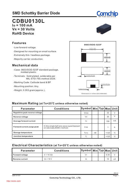
21 20
Forward voltage (mV)
QW-A1107
/
Comchip Technology CO., LTD.
REV:A Page 2
SMD Schottky Barrier Diode
Reel Taping Specification
P0
d
T
P1
E
Index hole
TSTG
-40
Tj
+125
O
C
+125
O
C
Electrical
Characteristics
(at
O
TA=25 C
unless
otherwise
noted)
Parameter
Forward voltage Reverse current
Conditions
IF = 10 mA VR = 10 V
Symbol Min Typ Max Unit
1mΒιβλιοθήκη 100uO75 C
10u
O
25 C
1u
100n
10n 0
O
-25 C
5
10 15 20 25 30
Reverse voltage (V)
Capacitance between terminals (PF)
Fig.3 - Capacitance between terminals characteristics
REV:A Page 4
分销商库存信息:
COMCHIP CDBU0130L
Mechanical data
-Case: 0603/SOD-523F standard package, molded plastic.
数字电源STNRG011规格书(中文版)
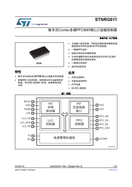
的增强型轻负载突发模式 • 一整套半桥保护 • 采用SO20封装
应用
• 开架式SMPS • 平板电视SMPS • ATX电源 • AC-DC 适配器
图1. 框图
BOOT HVG
FGND LVG
LLC_CS LLC_AUX
9.4.9 PFC状态机事件驱动(SMED) . . . . . . . . . . . . . . . . . . . . . . . . . . . . . . . . . 22
PFC算法 . . . . . . . . . . . . . . . . . . . . . . . . . . . . . . . . . . . . . . . . . . . . . . . . . . 22
9.2.4 Vline浪涌停止 . . . . . . . . . . . . . . . . . . . . . . . . . . . . . . . . . . . . . . . . . . . . 20
9.2.5 用于PFC控制的线路监控器 . . . . . . . . . . . . . . . . . . . . . . . . . . . . . . . . . . 20
9.4 PFC控制和故障管理 . . . . . . . . . . . . . . . . . . . . . . . . . . . . . . . . . . . . . . . . . 21
9.4.1 PFC资源 . . . . . . . . . . . . . . . . . . . . . . . . . . . . . . . . . . . . . . . . . . . . . . . . 21
- 1、下载文档前请自行甄别文档内容的完整性,平台不提供额外的编辑、内容补充、找答案等附加服务。
- 2、"仅部分预览"的文档,不可在线预览部分如存在完整性等问题,可反馈申请退款(可完整预览的文档不适用该条件!)。
- 3、如文档侵犯您的权益,请联系客服反馈,我们会尽快为您处理(人工客服工作时间:9:00-18:30)。
P0 P1 d Index hole E T
F B
Polarity
W C
P
A
12 0
o
D2
D1 D
W1
Trailer ....... .......
10 pitches (min)
Device ....... ....... ....... .......
Capacitance between terminals ( P F)
100
Fig.4 - Current derating curve
Average forward current(%)
f = 1 MHz Ta = 25 C
100
80
10
60
40
20
1 0 5 10 15 20 25 30
0 0 25 50 75 100
REV:A
QW-A1108
Page 4
Comchip Technology CO., LTD. /
分销商库存信息:
COMCHIP CDBU0130R
A
O
C C
O
Electrical Characteristics (at T A =25 C unless otherwise noted)
O
Parameter
Forward voltage Reverse current I F = 10 mA V R = 10 V
Conditions
Symbol Min Typ Max Unit
O
125
Reverse voltage (V)
Ambient temperature ( C)
Fig. 5 - VF Dispersion map
360
O
Fig. 6 - IR Dispersion map
1000 900
O
Fig. 7 - CT Dispersion map
50
O
Ta=25 C IF=10mA n=30pcs
Dimensions in inches and (millimeter)
0.028(0.70) Typ. 0.012 (0.30) Typ.
Maximum Rating (at T A =25 C unless otherwise noted)
O
Parameter
Repetitive peak reverse voltage Reverse voltage Average forward current Forward current,surge peak Storage temperature Junction temperature
P
4.00 ± 0.10
0.157 ± 0.004
P0
4.00 ± 0.10
0.157 ± 0.004
P1
2.00 ± 0.05
0.079 ± 0.004
T
0.23 ± 0.05
0.009 ± 0.002
W
8.00 ± 0.20
0.315 ± 0.008
W1
13.5 MAX.
0.531 MAX.
0603
Fig. 1 - Forward characteristics
1000 1m
125 C
O
Fig. 2 - Reverse characteristics
Forward current (mA )
100
Reverse current ( A )
100u
10u
75 C
O
10
C
O
1u
25 C
O
5
12
C
100n
Conditions
Symbol Min Typ Max Unit
V RRM VR IO 35 30 100 V V mA
8.3ms single half sine-wave superimposed on rate load(JEDEC method)
I FSM T STG Tj -40
1 +125 +125
(SOD-523F)
(mm) (inch)
REV:A
QW-A1108
Page 3
Comchip Technology CO., LTD. /
SMD Schottky Barrier Diode
Marking Code
Part Number CDBU0130R Marking Code
Ta=25 C VR=10V n=30pcs
45
Capacitance between terminals(pF)
Forward voltage (mV)
Reverse current (nA)
350
800 700 600 500 400 300 200 100
AVG:111nA
40 35 30 25 20 15 10 5 0
0.061 ± 0.002
D
178 ± 1
7.008 ± 0.04
D1
60.0 MIN.
2.362 MIN.
D2
13.0 ± 0.20
0.512 ± 0.008
0603
(SOD-523F)
(mm) (inch)
SYMBOL
E
1.75 ± 0.10
0.069 ± 0.004
F
3.50 ± 0.05
0.138 ± 0.002
-25 C
O
O
75
25
O
C0.1 0.2 0.3 0.4 0.5 0.6 0.7 0.8
-25
10n 1n 0 5 10
15
20
25
30
Forward voltage (V)
Reverse voltage (V)
Fig. 3 - Capacitance between terminals characteristics
Leader ....... .......
10 pitches (min)
End
Start
Direction of Feed
SYMBOL
A
1.00 ± 0.10
0.039 ± 0.004
B
1.85 ± 0.10
0.073 ± 0.004
C
1.00 ± 0.10
0.039 ± 0.004
d
1.55 ± 0.05
SMD Schottky Barrier Diode
CDBU0130R
I o = 100 mA V R = 30 Volts RoHS Device
Features
- Low reverse current. -Designed for mounting on small surface. -Extremely thin / leadless package. -Majority carrier conduction.
AVG:18.8pF
Ta=25 C F=1MHz VR=0V n=10pcs
340
330
AVG:335mV
320
310
0
REV:A
QW-A1108
Page 2
Comchip Technology CO., LTD. /
SMD Schottky Barrier Diode
-Terminals: Gold plated, solderable per MIL-STD-750,method 2026. -Marking Code: Cathode band & BQ -Mounting position: Any. -Weight: 0.003 gram(approx.).
VF IR 0.45 0.5 V uA
REV:A
QW-A1108
Page 1
Comchip Technology CO., LTD. /
SMD Schottky Barrier Diode
RATING AND CHARACTERISTIC CURVES (CDBU0130R)
BQ
BQ
Suggested PAD Layout
0603/SOD-523F SIZE (mm) A B C D E 1.70 0.60 0.80 2.30 1.10 (inch) 0.067 0.024 0.031
C D A E
0.091
B
0.043
Standard Package
Qty per Reel Case Type (Pcs) 0603/SOD-523F 4000 Reel Size (inch) 7
0.039(1.00) 0.031(0.80)
0603/SOD-523F
0.071(1.80) 0.063(1.60)
Mechanical data
-Case: 0603/SOD-523F standard package, molded plastic.
0.014(0.35) Typ. 0.033(0.85) 0.027(0.70)
