创锋线性模组CF116规格尺寸
W4施耐德Twido技术应用

施耐德Twido技术应用1.请问在TwidoSoft中如何使用超高速计数器的反射输出?为了使能已配置的反射输出工作,对于每个超高速计数器,有2个位必须置位为1,%VFCi.R对应反射输出0,%VFCi.S对应反射输出1。
2.Twido PLC 是否支持双字和浮点运算?Twido PLC 对双字和浮点运算的支持是根据型号的不同而不同,除一体型的 TWDLCAA10DRF不支持双字运算外,其它均支持双字运算,而对浮点运算而言,只有以下几种支持浮点运算:TWDLCAA40DRF,TWDLMDA40DUK,TWDLMDA40DTK,TWDLMDA20DRT。
3.在Twidosoft中,如何正确实现%MF2:= %IW1.0/ 2000的功能?正确的操作块示例如下:%MW0 := %IW1.0%MF0 := INT_TO_REAL( %MW0 )%MF2 := %MF0 / 2000.04.请问为什么启动TwidoSoft时,会出现以下错误信息:“Internal Error #2504 ...”?当使用NTFS分区(Windows XP或2000)时,可能是由于对TwidoSoft安装目录没有足够的访问权,例如。
用户必须具有对该目录的写权限,以允许TwidoSoft创建临时文件。
5.我有一台 Twido 的 PLC,在每次重新起动后 PLC 总是进入 STOP 状态,这是为什么? 如何让PLC 在每次重新起动后自动进入 RUN 状态?如果用户在编程软件中配置了运行/停止输入位,则当该输入位为0 时,重新起动后PLC总是进入 STOP 状态,而当该输入位为1或有上升沿时,重新起动后PLC将进入运行状态如果用户在编程软件中没有配置运行/停止输入位,则当“Auto Start in Run”复选框选中时重新起动后PLC将进入运行状态,如果当“Auto Start in Run”复选框不选中时,重新起动后PLC将进入停止状态,具体的操作为:(1).进入 Twidosoft 软件;(2).点击“program”→“scan mode edit”→“operating mode”;(3).在 operating mode 下将“Auto Start in Run”复选框选中后,可在编程软件没有配置运行/停止输入位时,重新起动后PLC自动进入运行状态。
SIMATIC NET 工业以太网交换机 SCALANCE XC-100 操作说明说明书

3.3
LED 指示灯 ..................................................................................................................... 19
3.4
SET 按钮 ........................................................................................................................ 20
5.3
电源 ................................................................................................................................ 33
5.4
信号触点 ......................................................................................................................... 35
危险 表示如果不采取相应的小心措施,将会导致死亡或者严重的人身伤害。
警告 表示如果不采取相应的小心措施,可能导致死亡或者严重的人身伤害。
小心 表示如果不采取相应的小心措施,可能导致轻微的人身伤害。
注意 表示如果不采取相应的小心措施,可能导致财产损失。
当出现多个危险等级的情况下,每次总是使用最高等级的警告提示。如果在某个警告提示中带有警告可能导致人身伤 害的警告三角,则可能在该警告提示中另外还附带有可能导致财产损失的警告。
CREATOR快捷CRWM-16墙上面板与中控配合使用编码说明

ole l l cton
一:
产品撷拾
CRE T A OR I 黼
1 产 品 功 能
CR M一 上面 板 与 中控 配 合 W 1 6墙 使 用 编码 说 明
l 国…
CE TR RAO 快捷CW 一6 R M 1是针对PMI 控 G I等中
主机 外 部 输 入 而 设 计 的 产 品 ,它 设 计 有 1 6个 输 入 按 键 ,配 合 C nrlS s m B i e o t yt ul r软 件 进 行 编 程 设 置 ; o e d
( ) 打开 C WM一 6网 络模 块 , 已经编 好 的程 序 2 R 1 把 变 量 中需 要 墙 上 面 板 控 制 的 指 令 变 量 拉 到 模 块 中 去 。 墙 上 面板 要 控 制 投 影幕 和 投 影架 的升 降 和停 止 ,就 把 控 制 指令 变量 拉到 模块 上 去就 可 以了 。其他 原理 一样 。
描 述 :pes ” “ rs1 ” 出数 字 脉 冲 。 下 C WM一 “ rs1 到 pes 6 输 按 R
WO V C S中找到 C WM一 6 将 模块 拉 过去 。 RK DE I E R 1,
1 6面板 上 的第 1 按 键 , 块 中 “rs1端将 输 出 1 个 模 pes ” 个
厘 蠹
l gb 。i
一 :
到
CM R1 W
2
面板上为 l 6个 输 入 按 键 , 键 、 示 灯 一 体 化设 按 指 计 。 系 统 安 装 完 毕 之 后 , 可 通 过 C nrl ytm o t S s o e Bie ul r软件 编程 定 义 按 键 指 令 代 码 , 行 各 种 逻 辑 指 d 执 令。 编程 完毕 之 后 , 接 通过 按 键 可 控 制 连 接至 中控 主 直
飞龙 wi
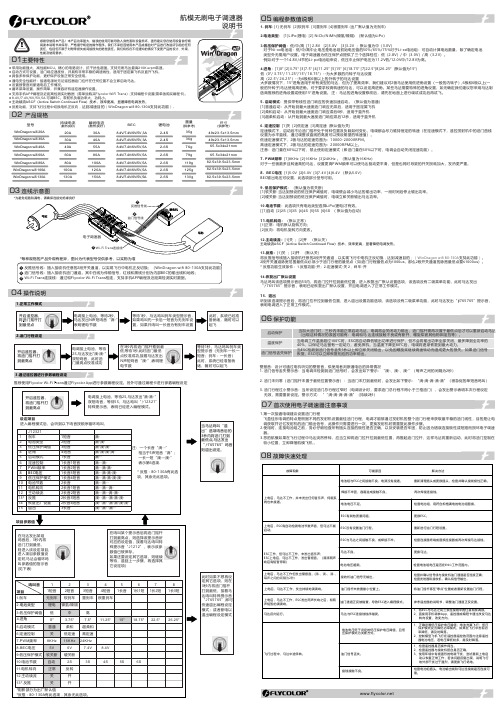
持续电流(散热良好)瞬间电流(散热良好)BEC尺寸(供参考)重量(供参考)20A 30A 40A 60A 30A 40A 55A 80A 锂电池型号79g 35g 36g 76g 49x23.5x13.5mm 65.5x34x21mm● 反推功能,支持飞行过程中切换电机正反向,达到减速目的(WinDragon wifi 80-130A 支持此功能)。
2-4S 2-4S 2-6S 2-6S 8.4V/7.4V/6V/5V ,5A 80A 100A 119g 2-6S 100A 120A 125g 2-6S 130A150A130g82.5x39.5x23.5mm2-6S航模无刷电子调速器WinDragon wifi 130AWinDragon wifi 100A WinDragon wifi 80A WinDragon wifi 60A WinDragon wifi 30A WinDragon wifi 40A WinDragon wifi 20A 8.4V/7.4V/6V/5V ,5A 8.4V/7.4V/6V/5V ,5A 8.4V/7.4V/6V/5V,5A8.4V/7.4V/6V/5V ,5A 82.5x39.5x23.5mm 82.5x39.5x23.5mm 65.5x34x21mm 49x23.5x13.5mm 02 产品规格04 操作说明1.正常工作模式2.油门行程设定3.通过遥控器进行参数编程设定推荐使用Flycolor Wi-Fi Trans 通过Flycolor App 进行参数编程设定。
另外可通过编程卡进行参数编程设定1. 刹车: [1] 无刹车 [2]软刹车 [3]重刹车 [4]很重刹车 (出厂默认值为无刹车)2.电池类型: [1]LiPo(锂电) [2] NiCb/NiMh(镍氢/镍隔) (默认值为Li Po )3.低压保护阈值:低/中/高 [1] 2.8V [2]3.0V [3]3.2V ;默认值为中(3.0V)对于Ni-xx电池组:低/中/高中止电压是电池组初始电压值的50%/65%/75%对于Li-xx电池组:可自动计算电池数量,除了确定电池 类型外无需用户设置。
格伦风暴线性格栅说明书 GL15

anddto introduced newer, better and efficient systems that addressed these needs. With an uncompromising approach towards quality and unflinching commitment to perfection, the company successfully established it’s a brand GLENSTORMS, in the segment.Application & Design:Duly powder coated extruded aluminium linear horizontal fixed bar grills, with 15 deg. deflection blade having pitch of 13 mm.Rating:Pressure Drop (∆Pg)-Velocity- 3 m/s10 mm of w.g.200 C7.3 mTemperature-Throw-Standard Construction:Dimension:1.Frame-Powder Coated Extruded Aluminium Section.Powder Coated Extruded Aluminium Section. 2.Louver-Height10051509200132501630020350234002745030No. OfBlades Frame:Louver:Size Limitations:Minimum Size- 4" (100 mm) ⬜70.9"(1800 mm) ⬜Maximum Size-All Dimensions are in mm.Model : GL 15Blade Deflection:0Model : GL 15(Noise rating)Model : GL 15Optional Features:-Available with Aluminium/steel Construction opposed blade Collar Damper with a screw driver operation system through the face of the grille.Available in black or white vertical spacers.Available louver thickness 0.6 mm, 0.8 mm, 1.0 mm & 2.0 mm from back.Model : G-HV Application & Design:All Dimensions are in mm..These grills are duly powder coated extruded aluminium double adjustable louver grills, with fronthorizontal and rear vertical.This grille controls the airstream in both the horizontal and vertical planes.It is Available in powder coated/anodised finish.Optional Features:-Model : G-HV(Noise rating)Model : G-CNV-OSF, G-CNV-BSFApplication & Design:These grills are powder coated extruded aluminium constructionwith horizontal fixed vanes normally used as a door grille.These grilles are carefully designed to suit the needs of air transferin those areas where privacy is not intended to be compromised.The construction is 100% non -vision ensures that no visibility ispossible in any condition.Model : G-CNV-OSF, G-CNV-BSF(Noise rating)Application & Design:All Dimensions are in mmThese Diffusers are duly powder coated extruded Aluminium ceiling mounted multi-slot Diffuser 2.Blade : 20 Ga, Aluminium Extrusion Section.Model : G-DSModel : G-DSNo. of Slots Air Flow (CFM)Velocity (FPM)Throw(m)Pressure Drop (in mm w.g)Noise (db)Performance TablePerformance Notes:1291201.9 5.1---59239 3.114-----88359 4.73215591202.23.51182394.414118159 3.6 6.3176359 6.632171762395.4122353197.225142352396.2142942997.822112942397.4243533599.5322535328710.7332041233512.642242345Pressure: All pressure are in mm of water.Maximum throw to a terminal velocity of 70 fpm.Throw data is based on supply air & room air being at isothermal conditions.The noise values are based on a room absoption of 10 db.Application & Design:These diffusers are powder coated extruded/stamped aluminium muti-cone ceiling diffuser withStandard Construction:1.Flange-Powder Coated Extruded Aluminium Section.Powder Coated Stamped Sheet.2.Ring-Model : G-RDC-FAvailable in powder coated-white finish.Other colour shades available on request.Optional Features:-Quick Selection:Model : G-RDC-F(Noise rating)Application & Design:Standard Construction:1.Flange-Powder Coated Extruded Aluminium Section.Model : G-RDC-GPowder Coated Stamped Sheet.2.Ring-All Dimensions are in mm.These diffusers are duly powder coated stamped aluminium multi-cone grid type ceiling diffuser with removable centre core helps to facilitate cleaning and damper adjustment.Out to out size: 595 X 595 mm neck size 450 x 450 mm.Model : G-RDC-GQuick Selection:Available in powder coated-white finish.Other colour shades available on request.Optional Features:-(Noise rating)Application & Design:Size Limitations:Minimum Size-11.81 in.(300 mm) x 11.81 in.(300 mm) 23.62 in.(600 mm) x23.62 in.( 600 mm)Maximum Size-Model : G-RDC-PNeck sizeNeck Velocity,fpm Velocity pressure,mm of wg. Total pressure, mm of wg.Total pressure, mm of wg.Total pressure, mm of wg.Flow Rate, CFMFlow Rate, CFMFlow Rate, CFMNCNCNCThrow (ft.)Throw (ft.)Throw (ft.)Performance TablePerformance Notes:200 x 2000.450.73 1.06 1.44 1.87 2.36 2.924000.255000.406007000.558000.789001.0110001.26 1.57145180205240274306340----2124292-53-64-74-85-96-96-100.75 1.14 1.65 2.23 2.92 3.70 4.57---192427322152703243804314865403-64-85-96-106-117-128-121.04 1.652.363.224.215.336.57310390465560624702780--15212431344-85-106-117-128-139-1410-15 250 x 250300 x 300Pressure: All pressure are mm of water gauge.The NC values, sound pressure level, are based on a room absorption of 10 DB & one diffuser. Blanks(-) indicates an NC level below 15Throw of air is given in feet (each side) with terminal velocities of 100 fpm & 50 fpm (maximum). Air flows is in cubic feet per minute, cfm.Model : G-SWD-F Application & Design:Fixed blade swirl diffusers presents an attractive and aerodynamically efficient alternative to conventional square ceiling terminals. These diffusers are design to produce a horizontal, radial air pattern with a turbulent, high induction jet characteristics and are ideally suited for applications with high heating or cooling differentials.It is manufactured from aluminium with press formed blades, the units can be supplied complete with a duct mounting collar for easy assembly. The steel duct mounting collar can be used as a means of fixing and supporting the diffuser from rigid duct work, or alternatively ceiling support brackets (supplied as standard) can be fitted for use with flexible ducting.Model : G-SWD-F Selection CriteriaJet throw data is expressed in meters and is based on a terminal velocity of 0.5 m/s and a 10 C cooling differential.NR levels are based on sound pressure levels with an assumed 8 dB room absorption factor. pressure loss data is shown in terms of static pressure loss (Pa) based on a diffuser fitted with aDM collar, or for a diffuser installed in a WTP plenumPerformance TableG-CDStandard Construction:1.Flange-Powder Coated Extruded Aluminium Section.Powder Coated Stamped Sheet.2.Ring-Application & Design:All Dimensions are in mm.Model : G-CD-SFModel : G-CD-SF(Noise rating)Model : G-JND Application & Design:These diffusers are powder coated aluminium rotatable jet nozzle and diffuser which allows bothAll Dimensions are in mm.Model : G-JNDPerformance Notes:(Noise rating)Application & Design:These diffusers are duly powder coated aluminium double skin eye-ball type rotable jet nozzle .This type of supply nozzles are capable of delivering air to spaces where long distance penetration and low noise levels are required. Suitable for cold and warm air supply applications, these versatile adjustable units are ideal for providing focussed ventilation or where precision is required. Where grouped penetration can be considerably enhanced.Inner Cowl-Outer Cowl-High grade Aluminum spinning High grade Aluminum spinning Standard(a) Epoxy polyester powder coated of white/pure white.(b) Natural Anodized.Finish-Standard Construction:Model : G-JNSize Limitations:Minimum Size- 4 in.(100 mm) dia. 16 in.(400 mm) dia.Maximum Size-Flow G-JNRate ThrowPressureNoiseLossSize cfm m Pa dBA100271035<20 55207527 803015042125361012<20 421123<20 72205020 105301503716048108<20 301320<20 6320 5224 148301003220063105<20 1051718<20 70203321 14830802525080107<20 1611814<20 224203021 31730702331510110<5<20 2072010<20 31730282040013510<5<202731208<203172415<204133030<20Model : G-JNModel : G-SD Application & Design:ODOGModel : G-SD******************* +91 9911214199, 8585919596。
MB16AWP 无线便携式显示器用户指南说明书
MB16AWP无线便携式显示器用户指南第一版2022 年 1 月版权所有 © 2022 ASUSTeK COMPUTER INC. 保留所有权利。
未经 ASUSTeK COMPUTER INC. ("ASUS") 明确书面同意,不得以任何形式或通过任何方式复制、传播、转录本手册的任何部分,包括其中介绍的产品和软件,也不得存储到检索系统中或翻译成任何语言,购买者出于备份目的而保留的文档除外。
在下列情况下,不能享受产品保修或维修服务:(1) 产品被修理、修改或改动,除非此类修理、修改或改动得到 ASUS 的书面授权;(2) 产品序列号损毁或缺失。
ASUS“按原样”提供本手册,不提供任何明示或隐含的担保,包括但不限于对于适销性或针对特定目的的适用性的隐含担保或条件。
无论在任何情况下,ASUS 及其董事成员、高级职员、员工或代理不对由于本手册或产品中存在任何缺陷或错误而导致的任何间接、特殊、偶然或必然损失(包括收益损失、业务损失、不能使用或数据丢失、业务中断等)承担任何责任,即使 ASUS 已被告知此类损失的可能性。
本手册中包含的规格和信息仅供一般性参考,可能会随时变更而无需另行通知,因此不应构成 ASUS 的承诺。
ASUS 对本手册(包括其中介绍的产品和软件)中可能存在的任何错误不承担任何责任。
本手册中出现的产品名称和公司名称可能分别是或不是相应公司的注册商标或版权,仅用于标示或解释目的,无意侵犯其所有者的权益。
ii目录 (iii)声明 (iv)安全信息 (xi)保养和清洁 (xii)中国产品回收服务 (xiii)北美可充电电池回收服务 (xiii)产品欧盟能源标识信息 (xiii)第 1 章:产品介绍1.1 欢迎使用! .....................................................................................1-11.2 物品清单.........................................................................................1-11.3 显示器简介 .....................................................................................1-21.3.1 前部概览/侧面概览 ........................................................1-2第 2 章:设置2.1 显示器竖立位置 ..............................................................................2-12.2 调整显示器 .....................................................................................2-12.3 连接线缆.........................................................................................2-22.4 打开显示器电源 ..............................................................................2-22.5 执行无线投影..................................................................................2-32.6 将显示器连接到 Internet ................................................................2-42.7 更新无线投影固件 ..........................................................................2-52.8 通知 ................................................................................................2-6第 3 章:一般说明3.1 OSD(屏幕显示)菜单...................................................................3-13.1.1 如何重新配置 ..................................................................3-13.1.2 OSD功能介绍.................................................................3-23.2 规格摘要.........................................................................................3-93.3 外形尺寸.......................................................................................3-113.4 故障排除(常见问题) .................................................................3-123.5 支持的运行模式 ............................................................................3-13iii联邦通信委员会声明本设备符合 FCC 规则第 15 部分的要求。
电源保护系列C F-Frame和PD Frame ELC电流限制器安装说明说明书
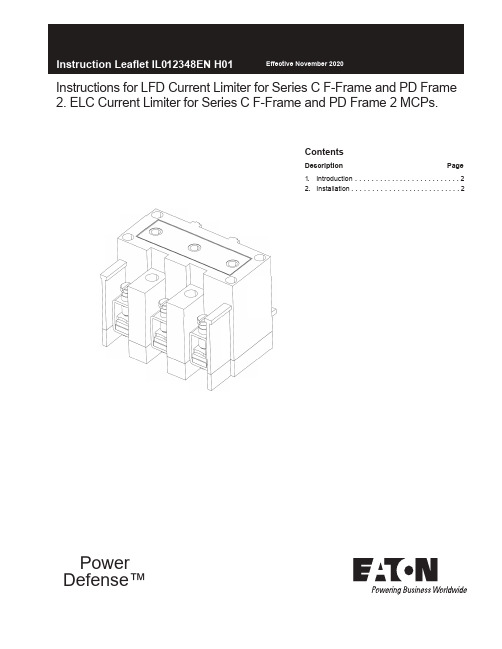
Contents Description Page 1.Introduction . . . . . . ... ..... . . . . ... ... ...22.Installation . . . . . . . . . . . . ....... ... .... . 2Instructions for LFD Current Limiter for Series C F-Frame and PD Frame 2. ELC Current Limiter for Series C F-Frame and PD Frame 2 MCPs. PowerDefense™2Instruction Leaflet IL012348EN H01Effective November 2020 Instructions for LFD Current Limiter for Series C F-Frame and PD Frame 2. ELC Current Limiter for Series C F-Frame and PD Frame 2 MCPs.EATON EQUIPMENT WHILE IT IS ENERGIZED. DEATH, SEVERE PERSONAL INJURY, OR SUBSTANTIAL PROPERTY DAMAGE CAN RESULT FROMCONTACT WITH ENERGIZED EQUIPMENT. ALWAYS VERIFY THAT NO VOLTAGE IS PRESENT BEFORE PROCEEDING WITH THE TASK AND ALWAYS FOLLOW GENERALLY ACCEPTED SAFETY PROCEDURES. EATON IS NOT LIABLE FOR THE MISAPPLICATION OR MISINSTALLATION OF ITS PRODUCTS. 2 . INSTALLATION IF REMOVING A CIRCUIT BREAKER INSTALLED IN AN ELECTRICAL SYSTEM, MAKE SURE THERCIRCUIT BREAKERS IS SWITCHED TO THE OFF POSITION AND THERE IS NO VOLTAGE PRESENT WHERE WORK IS TO BE PREFORMED. SPECIAL ATTENTION SHOULD BE PAID TO REVERSE FEED APPLICATIONS. THE VOLTAGES IN ENERGIZED EQUIPMENT CAN CAUSE DEATH OR SEVERS PERSONAL INJURY.Type ELCCurrent LimiterMax.Amps.Terminal wire connectors areUL listed for standard wire sizes as UL 486A or 486B Optional on special order for copper cable onlyStandard Aluminum Terminals Nonstandard Terminals (Steel)Wire RangeAWG(mm²)50100150#14-2#1-410#1-410(2.5-35)(50-95)(50-95)#14-2 ²(2.5-35)Wire Range AWG (mm²)The User is cautioned to observe all recommendations,warnings, and cautions relating to the safety of personnel and equipment as well as all general and local health and safety laws, codes, and procedures.The recommendations and information contained herein are based on Eaton experience and judgment, but should not be considered to be all-inclusive or covering every application or circumstance which may arise. If any questions arise, contact Eaton for further information or instructions.1. INTRODUCTION Current limter circuit breaker or current limiter/MCP combinations are designed for maximum protection and coordination, and should be applied in accordance with the current limiter nameplate. For example, the LFD3150R current limiter is for use with thermal-magnetic or electronic F-Frame or PD2, whereas the ELC3030R current limiter is only to be used with the 30A MCP.This noninterchangeability feature is made possible by combinations of molded projections and grooves and by several sizes of pierced and threaded terminals. Standard terminals are provided with the current limiter and are suitable for either copper or aluminum wire as shown in Table 1-1.For this publication, the term circuit breaker shall also include motor circuit protector.Table 1-1 Current Limiter Terminals Wire SizesNote : Before attempting to Install the current limiter, check that the catalog number is correct and that the rating of the accessory satisfies job requirements.A circuit breaker that is mounted in an electrical system must be removed to install the current limiter.2-1. Remove terminals from load end of circuit breaker.Note: During next step, molded projections of current limiter should fit inside the molded grooves in the circuit breaker.2-2. Position threaded terminals of current limiter under circuit breaker terminals.2-3. Secure current limiter to circuit breaker using the threee short screws and lockwashers (Table 2-1) provided in the packing envelope. Torque load screws (Table 2-1).2-4. Secure current limiter to mounting panel using long #8-32 screws provided in the packaging envelope.2-5. Connect cables to current limiter. Table 1-1 shows available connector types.Current LimiterAmperes Clamping Screw Torque value lb-in (N•m)25-70100-150 (also LFD3150R)#12-241/4-204060 to 80 4.52(6.78 to 9.4)˜²Eaton assumes no responsiblity for malfunctioning accessoriesinstalled by the customer.A circuit breaker that is mounted in an electrical system must be removedto install the current limiter.Table 2-1 Clamping Screw Torque Values and Usage.Instruction Leaflet IL012348EN H01 Instructions for LFD Current Limiter for Series C F-Frame and PD Frame 2.ELC Current Limiter for Series C F-Frame and PD Frame 2 MCPs.EatonElectrical Sector1000 Eaton BoulevardCleveland, OH 44122United States877-ETN-CARE(877-386-2273) © 2014 EatonAll Rights Reserved Printed in USA Publication No. IL012348EN Part No. IL012348ENH01Eaton is a registered trademark.All other trademarks are property of their respective owners.The instructions for installation, testing, maintenance, or repairherein are provided for the use of the product in general commercialapplications and may not be appropriate for use in nuclear applica-tions. Additional instructions may be available upon specific requestto replace, amend, or supplement these instructions to qualify themfor use with the product in safety-related applications in a nuclearfacility.This Instruction Booklet is published solely for information purposesand should not be considered all-inclusive. If further information isrequired, you should consult an authorized Eaton sales representa-tive.The sale of the product shown in this literature is subject to theterms and conditions outlined in appropriate Eaton selling policiesor other contractual agreement between the parties. This literatureis not intended to and does not enlarge or add to any such contract.The sole source governing the rights and remedies of any purchaserof this equipment is the contract between the purchaser and Eaton.NO WARRANTIES, EXPRESSED OR IMPLIED, INCLUDINGWARRANTIES OF FITNESS FOR A PARTICULAR PURPOSE ORMERCHANTABILITY, OR WARRANTIES ARISING FROM COURSEOF DEALING OR USAGE OF TRADE, ARE MADE REGARDINGTHE INFORMATION, RECOMMENDATIONS, AND DESCRIPTIONSCONTAINED HEREIN.In no event will Eaton be responsible to the purchaser or user incontract, in tort (including negligence), strict liability or otherwisefor any special, indirect, incidental or consequential damage or losswhatsoever, including but not limited to damage or loss of use ofequipment, plant or power system, cost of capital, loss of power,additional expenses in the use of existing power facilities, or claimsagainst the purchaser or user by its customers resulting from theuse of the information, recommendations and description containedherein.Effective November 2020。
CF611

大冰晶盒成品
后壳/10108
CFH11 ABS707
PVC 2C*1.0MM2*2.0M 两平插黑
电源线
遥控器组件 股线组1 环保 股线组2 环保 股线组3 环保 兰色单股线 环保
CF611 遥控器组件
CF611 CF611 CF611 L=600mm L=280mm L=600mm 棕色单股线 棕色单股线 兰色单股线
CF611RI WAI-A077/A 220-240V成品委外生产
主机PC电源板
中机座 翘板开关 檔風板/Q-15509 前门/10107 水箱/10117
CFH11 ABS707
SC787 16(4)A 250VAC T85 CF609 ABS707 B黑環保
防水板
蜂窝支架/10120
PP纸
压片 转动座 弹簧 水泵挂架 水泵 水泵转座 水位开关组件电源插头蓝来自微动开关橙蓝 橙
翘板开关
电流保险丝
黑 灰
主电路板
马达
红
蓝 白 紫
起动电容
同步马达
负离子
水泵
整机电路图
三、产品爆炸图:
备注
遥控器 机体 冰晶盒
曲柄 IC板
微动开关
水泵、左右侧板、水箱、波纹管
后壳
防倒开关 马达轴 马达
水位开关
电流保险丝
主电路板 热敏电阻
按键PCB
显示PCB
整机电路图
3.5*10 割尾
C D E F G
螺 丝 螺 丝 螺 丝 梅花头螺丝 螺 丝 螺 丝 圆头螺丝
3*16 割尾 白锌 4*10 割尾 不锈钢螺丝 3.5*8 割尾 镀黑 3.5×11割尾 白锌
3.5*30 尖尾 白锌
ITX-M19 VER 1.6主板说明书

订购产品前,请向经销商详细了解产品性能是否符合您的需求。本手册所涉及到 的其他商标,其所有权为相应的产品厂家所拥有。
本手册内容受版权保护,版权所有。未经许可,不得以机械的、电子的或其它任 何方式进行复制。 欲知更多信息,请访问:
研域工控网站: 研域工控技术支持邮箱:sh.fawang@ 研域工控技术支持QQ:2850579877
12产品规格产品规格处理器板载intel?celeron1037u18ghz双核处理器可兼容intel?sandyivybridgeceleroni3i5i7bga1023低功耗处理器芯片组采用intel?nm70或hm65高速芯片组内存支持单通道ddr316001333内存最大支持8gb显示功能集成intel?hdgraphics核心显卡提供vgalvdshdmi显示输出支持单独显示双显模式扩展模式lvds支持双通道24bititxm19于基于intel?celeron1037u处理器的miniitx工业主板网络功能集成1个realtekrtl8111e千兆网卡可选做2个千兆网卡支持网络唤醒pxe功能音频功能集成alc6626声道高保真音频控制器支持miclineout功放支持25w双声道扩展总线提供1个minipcie插槽支持wifi3g模块1个msata插槽支持usbwifi或ssd固态硬盘ssd传输速度可达6gbps存储功能提供2个sata硬盘接口提供1个25寸sata笔记本硬盘位背板io接口4usb20接口usb2与lan2二选一1hdmi显示接口1vga显示接口1rj45网络接口可选做2个千兆网卡1lineout接口绿色1mic接口红色112vdc电源输入接口内置接口1ps2键盘鼠标接口16pin1jvga1接口25pin与db15同信号1jhdm1接口28pin与背板io接口的hdmi1可以同时使用1lvds接口215pin支持双通道24bit双81lvds背光接口16pinitxm19于基于intel?celeron1037u处理器的miniitx工业主板1前置音频接口25pin1前置功放接口14pin1前面板功能按钮和指示灯接口25pin2rs232串口且com12第9pin支持带电功能4usb20接口25pin14pinatx12v输入输出电源接口12p蓝色电源座子1lpt打印接口1sim卡座gpio功能支持4路输入输出gpio功能散热系统14pincpu风扇13pin系统风扇bios32mbflashromwatchdog功能支持硬件复位功能256级0255秒电源特性采用dc12v电源供电尺寸环境主板尺寸
Belden 10 AWG RG-8型高频线缆说明书

-40°C To +75°C 80°C 114.591 Kg/Km 667.230 N 101.600 mm
Applicable Specifications and Agency Compliance (Overall)
Applicable Standards & Environmental Programs
METRIC MEASUREMENT VERSION
7810A Coax - RG-8 Type
Freq. (MHz) Attenuation (dB/100m)
30
2.2967
50
3.05133
150
5.18398
220
6.36514
450
9.28523
900
13.3209
1500
17.4549
1800
Physical Characteristics (Overall)
Conductor AWG:
# Coax AWG Stranding Conductor Material
Dia. (mm)
1
10 Solid
BCCA - Bare Copper Covered Aluminum 2.7432
Insulation Insulation Material:
817
900
575
1500
437
1800
399
2000
375
2500
334
3000
305
3500
282
4500
247
5800
217
6000
213
Max. Operating Voltage - Non-UL: Voltage 300 V RMS
AlcatelOptinex1660SM(中)

4 概述
1660SM 是一个传输和交叉连接各种 PDH 和 SDH 信号的 STM-1/4/16 网 元。它可以配置成一个多终端或插分复用器。另外系统还可配置成一个 小型交叉连接,矩阵容量在高阶 VC 级可达 96x96 等效 STM-1,在低阶 VC 级可达 64x64 等效 STM-1。 图 1 所示为 1660SM 采用的复用结构
6 机械结构
18
6.1 主子框机械结构
18
6.2 下子框机械结构
21
7 技术参数前言
Alcatel OPTINEX™ 1660SM 同步分插复用器是 OPTINEX™传输产品系列 之一,符合 ITU-T 有关同步数字系列(SDH)的 G.707 和 G.709 建议。
1660 SM 是速率为 155 (STM-1),622 (STM-4)Mbit/s 和 2048(STM-16)Mbit/s 的传输设备,与已有的准同步系统兼容。在线 型链路、环网和网状网络应用中, 1660SM 可配置为多线路终端复用器, 分插复用器或一个小型的交叉连接。在各种应用中,1660SM 都可提供 多种网络保护方案。
多种不同的支路信号可以复用或插分进 STM-1/4/16 群路。1660SM 提 供对称的结构模式,所有业务端口(PDH 和 SDH)都具有同样的功能及 运行模式,并且支路及群路间没有特别的分别。这样在同一个节点,可
终接多个重叠或对等的环。业务口可以是 1.5Mb/s,2Mb/s, 34Mb/s, 45Mb/s,140Mb/s,STM-1 电,STM-1/STM-4/STM-16 光。无阻塞矩阵 功能可以在低阶 VC 级等效 64xSTM-1 全接入。
1660SM 通过本端接口与一本地个人计算机或通过 Q 接口与网络管理系 统相连,便可获得告警、性能监视、配置及所有与设备状态有关的信 息。与本地终端及与网元管理器相连的接口都是基于 QB3 CMIP 协议栈 及管理信息标准的。在所有配置中,链路维护均由一个公务通道来完 成。根据 ITU-T 建议,辅助信道通过开销字节传输。
PCS-9616D_X_说明书_国内中文_国内标准版_X_R1.30
外部回路 当把装置输出的接点连接到外部回路时,须仔细检查所用的外部电源电压,以防止所连接的回
路过热。 连接电缆
仔细处理连接的电缆避免施加过大的外力。
版权声明 © 2015 NR. 南京南瑞继保电气有限公司版权所有
警告!
为增强或修改现有功能,装置的软硬件均可能升级,请确认此版本使用手册和您购买的产品相 兼容。
警告!
电气设备在运行时,这些装置的某些部件可能带有高压。不正确的操作可能导致严重的人身伤 害或设备损坏。
只有具备资质的合格专业工作人员才允许对装置或在装置临近工作。工作人员需熟知本手册中 所提到的注意事项和工作流程,以及安全规定。
1.1 应用范围 ............................................................................................................................. 1 1.2 功能配置 ............................................................................................................................. 1 1.3 性能特征 ............................................................................................................................. 2 1.4 订货须知 ............................................................................................................................. 3 1.5 产品执行标准...................................................................................................................... 3 第 2 章 技术参数 .............................................................................................................................. 5 2.1 电气参数 ............................................................................................................................. 5 2.2 机械结构 ............................................................................................................................. 6 2.3 环境条件参数...................................................................................................................... 7 2.4 通信端口 ............................................................................................................................. 7 2.5 型式试验 ............................................................................................................................. 8 2.6 认证 .................................................................................................................................... 8 2.7 保护功能 ............................................................................................................................. 9 2.8 管理功能 ............................................................................................................................. 9 第 3 章 工作原理 .............................................................................................................................11 3.1 概述 ...................................................................................................................................11 3.2 装置启动元件.....................................................................................................................11 3.3 (短充)过流保护和零序保护 .......................................................................................... 12 3.4 (长充)过流保护和零序保护 .......................................................................................... 13 3.5 同期功能(可选) ............................................................................................................ 14 3.6 异常告警 ........................................................................................................................... 15 3.7 采样数据异常的处理......................................................................................................... 16 3.8 遥控、遥测、遥信功能 ..................................................................................................... 16 3.9 时间管理 ........................................................................................................................... 16 第 4 章 硬件描述 ............................................................................................................................ 19
Fractal Design Terra 机箱 产品简介说明书

Index347TerraCrafted to elevateTerra是一款旨在小型PC游戏机箱,重塑玩家耳目一新的游戏体验。
在外形设计上,Terra的灵感来自现代游戏玩家的居家环境感受,机身厚实的阳极化铝板切割而成、再由CNC数控机床打磨工艺与FSC认证实心胡桃木共同实现精致细节的设计。
配备了PCIe 4.0 Riser线缆和一个可移动调节的中央隔板,实现组装灵活性与兼容性的完美结合,可容纳长达322mm的高性能显卡安装空间。
这些无不彰显Terra的尽善尽美。
主要特点• 10.4 L的体积,不但节省空间,更可安装长达322mm的高性能显卡• 经过FSC认证的实心胡桃木前面板,给Terra增添了一丝自然元素• 享受优美且高级的阳极化铝制外观,以及正面8mm厚铝制面板• 可平滑移动的中央隔板能提供30mm调整空间,让使用者随心发挥硬件搭配,实现组装理想架构• 前置I/O接口,包含一个铝制电源开关按键和两个USD端口,其中包含一个20Gbps USB Type C • 配备PCIe 4.0 Riser线缆,方便使用• 2.5”硬盘专用支架,最多可容纳两个SSD• 侧板底部简单开启方式与顶盖后部皮革质感的拉环,使整个机箱打开方式变得轻松且别具一格• 全身通风设计,最大程度保证自然气流进出,以获得足够的散热需求• 两侧与上方面板采用可锁定设计,可安全运输整机至目的地一般规格规格3.5"/2.5"硬盘支架2.5"专用硬盘支架5.25”硬盘支架扩展槽主板兼容性电源类型前置接口总风扇支持前置风扇顶部风扇后部风扇底部风扇防尘网前置散热器顶置散热器后置散热器侧面散热器底部散热器PSU限长主板支架显卡最大尺寸配置• 包含0个,共0个位置• 2个(内附)• 0• 3• mITX• SFX-L/ SFX• 1x USB Type-C 20Gbps(USB 3.2 Gen 2x2),• 1x USB Type-A 5Gbps(USB 3.0),电源按钮• 1x 120 mm• 0• 0• 0• 1x 120 mm• 0• 0• 0• 0• 1x 120mm(如果安装200 mm GPU且无SSD,则121 mm宽)• 0• 130 mm• 可调节29.4 mm显卡最大尺寸配置• 0• 2一般规格规格GPU限长GPU限宽1*如果GPU高度低于131 mm GPU限宽 2*如果GPU高度为131-145mm GPU限高*CPU散热器限高*额外备注免工具一键式锁扣设计显卡最大尺寸配置• 322 mm• 72 mm• 62 mm• 145 mm• 48 mm• 主板主支架可调节,它影响最小/最大显卡宽度及CPU冷却器高度。
R816P 无线布撤防模块说明书
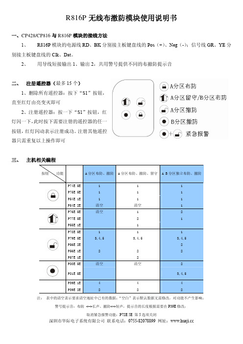
R816P无线布撤防模块使用说明书
一、CP428/CP816与R816P模块的接线方法
1、R816P模块的电源线RD、BK分别接主板键盘线的Pos(+)、Neg(-);信号线GR、YE分别接主板键盘线的Clk、Dat。
2、用导线短接输出1、输出2,共用警号提供不同的布撤防提示音
1、删除所有遥控器:按下“S1”按钮,
直至红灯由亮变灭即可
2、注册遥控器:按一下“S1”按钮,红
灯闪一下,此时按下需要注册的遥控器的任一
按钮,红灯闪动表示注册成功。
注册其他遥控
器只需重复以上操作即可
三、 主机相关编程
注:表中的清空表示要求清空地址中已有的数据;“空白”表示默认数据无需修改,对功能不产生影响;
警号提示音:布防<–>长声、撤防<->短声,提示音的长度根据需要在P39E修改;
取消紧急报警功能:P72E 5E 第5选项关闭
深圳市华际电子系统有限公司联系电话:*************网址:。
艾特顿电源防御模具外围路由器断路器PDG12F0015TFFJ的产品说明说明书

Eaton PDG12F0015TFFJEaton Power Defense molded case circuit breaker, Globally Rated, Frame 1, Two Pole, 15A, 25kA/480V, T-M (Fxd-Fxd) TU, Standard Line and Load (PDG1X2T125)Eaton Power Defense molded case circuit breakerPDG12F0015TFFJ 78667925591976 mm 139.7 mm 50.8 mm 0.907 kg Eaton Selling Policy 25-000, one (1) year from the date of installation of theProduct or eighteen (18) months from thedate of shipment of the Product,whichever occurs first.RoHS Compliant CCC MarkedUL 489CSAIEC 60947-2Product NameCatalog Number UPCProduct Length/Depth Product Height Product Width Product Weight WarrantyCompliancesCertifications15 AComplete breaker 1Two-polePD1 Global Class A T-M (Fxd-Fxd) TU600 Vac600 VStandard Line and Load25 kAIC at 480 Vac 25 kAIC Icu/ 25 kAIC Ics/ 53 kAIC Icm @380-415V (IEC) 35 kAIC @240V (UL) 14 kAIC @600V (UL/CSA) 25 kAIC @480V (UL) 22 kAIC Icu @125 Vdc 22 kAIC Icu @250 Vdc35 kAIC Icu/ 35 kAIC Ics/ 73.5 kAIC Icm @240V (IEC)Eaton Power Defense MCCB PDG12F0015TFFJ 3D drawing Consulting application guide - molded case circuit breakers Power Defense brochurePower Defense molded case circuit breaker selection poster Power Defense technical selling bookletPower Defense molded case circuit breakers - Frame 1 product aidAmperage Rating Circuit breaker frame type Frame Number of poles Circuit breaker type Class Trip Type Voltage rating Voltage rating - max TerminalsInterrupt rating Interrupt rating range3D CAD drawing packageApplication notesBrochuresCatalogsMolded case circuit breakers catalogCertification reportsPDG1 CSA certificationPDG1 UL authorizationEU Declaration of Conformity - Power Defense molded case circuit breakersPower Defense Declaration concerning California’s Proposition 65PDG1 CCC certificationInstallation instructionsPower Defense Frame 1-2-3-4 IP door barrier assembly instructions -IL012278ENPower Defense Frame 1 UL global box terminal (steel) 125A 2P -IL012165EN H02Power Defense Frame 1 UL global screw terminal end cap kit metric 125A 2P - IL012170ENPower Defense padlockable handle lock hasp top off only installation instructions - IL012226ENPower Defense Frame 1 UL global DIN rail adapter 2, 3, 4-pole -IL012185ENPower Defense Frame 1 UL global handle block non padlockable -IL012177ENPower Defense Frame 1 UL global screw terminal end cap kit 125A 2P - IL012162ENPower Defense Frame 1 UL Global variable depth rotary handle mech installation instructions - IL012308ENPower Defense Frame 1 UL global handle block padlockable -IL012178ENPower Defense Frame 1 Instructions - IL012152ENPower Defense Frame 1 UL global tunnel terminal (aluminum) 125A 2P - IL012166EN H02Power Defense Frame 1 UL global Padlockable Handle Lock Hasp -IL012225ENPower Defense Frame 1 UL global interphase barrier instructions -IL012313ENPower Defense Frame 1 UL global interphase barrier - IL012176EN Power Defense Frame 1 UL global handle block padlockable off only - IL012179ENPower Defense Frame 1 UL global lock padlockable handle haspIL012180ENInstallation videosEaton Corporation plc Eaton House30 Pembroke Road Dublin 4, Ireland © 2023 Eaton. All Rights Reserved. Eaton is a registered trademark.All other trademarks areproperty of their respectiveowners./socialmediaPower Defense Frame 1 UL Global Aux, Alarm, ST and UVR Animated Instructions.rh Power Defense Frame 3 Variable Depth Rotary Handle Mechanism Installation How-To VideoPower Defense Frame 6 Trip Unit How-To Video Power Defense Frame 5 Trip Unit How-To VideoPower Defense Frame 2 Variable Depth Rotary Handle Mechanism Installation How-To VideoPower Defense molded case circuit breakers Power Defense BreakersEaton Power Defense for superior arc flash safety Eaton Specification Sheet - PDG12F0015TFFJ Power Defense time current curve Frame 1 - PDG1Single and double break MCCB performance revisited Molded case and low-voltage breaker health Safer by design: arc energy reduction techniquesMultimediaSpecifications and datasheetsTime/current curvesWhite papers。
CREATRUE CF100倒车影像摄像头 规格书

◆ 产品介绍:
CF100是一款高清防水倒车影像摄像头,采用美国Omnivision的高品质二合一芯片,具有以下优点。
1.采用CMOS A 级图像传感器,清晰度和最低照明度比好,成像清楚。
2.具有障碍物位置参考线,便于车后障碍物距离确定。
3.带红外灯补光,夜晚夜视效果非常好。
4. 锌合金外壳,独特的防水处理,牢固安全防水。
5. 出厂经过高压浸水测试和产品老化测试,产品性能更稳定。
图1-CF100外观图科锐奇-专业智能工控产品供应商CF100倒车影像摄像头规格书
CF100科 锐 奇-专 业 智 能 工 控 产 品 供 应 商CF100倒车影像摄像头规格书。
VIAVI 16-lane CEM 插接器数据表说明书

Data SheetVIAVIXgig 16-lane CEM Interposer© 2023 VIAVI Solutions Inc.Product specifications and descriptions in this document are subject to change without notice.Patented as described at /patentsxgig-16-lane-cem-interposer-ds-snt-nse-ae 30193520 901 0123Contact Us+1 844 GO VIAVI (+1 844 468 4284)To reach the VIAVI office nearest you, visit /contactVIAVI SolutionsKit ContentsApplicationsWorking together with the VIAVI PCIe 5.0, Analyzer/Exerciser/Jammer platform, this Interposer enables debug and verification of new ICs, new system hardware designs, FPGA firmware, validation of system BIOS and software, and supports manufacturing test.The Xgig 16-lane, CEM slot Interposer is inserted into a 16-lane PCIe slot in the host system, and an endpoint card is installed into the top 16-lane slot connector creating the test data path. Cables connect the Interposer to the VIAVI protocol Analyzer/Exerciser/Jammer platform chassis.The photo to the right shows the Interposer connections to the Analyzer chassis, while the diagram indicates the signal path with DUT devices attached. Note that this Interposer requires an open DUT system chassis while in use.When operating in Analyzer mode, the DUT data is captured (tapped) from both the upstream and downstream signal paths as inputs to the Analyzer. When operating in Jammer mode, or Analyzer/Jammer mode, the Interposer data path is switched to route data into and out of the Xgig analysis system.VIAVI offers a variety of other Interposer types for connecting into many popular PCIe system applications, including other CEM, U.2, M.2, EDSFF , Flying-Lead and others.Ordering Information*CEM: Card Electro-Mechanical Specification (a PCIe spec)analysis toolsVIAVI PCle5Analysis SystemVIAVI Xgig 16-lane, CEM slot InterposerVIAVI Xgig5P-PCIe5-X16-CIC Interposer。
it6616fn规格书

it6616fn规格书
IT6616FN规格书是一份详细说明IT6616FN芯片特性和性能的文档,旨在帮助
用户了解该芯片的功能和技术参数。
IT6616FN是一款高性能的数字视频接口转换
器芯片,具有多种功能和特性,适用于各种视频信号转换和处理的应用场景。
首先,IT6616FN芯片支持多种输入和输出视频信号格式,包括HDMI、DVI、DisplayPort等,可以实现不同信号格式之间的转换和处理。
同时,IT6616FN还支
持高达4K分辨率的视频信号传输,能够满足高清视频播放和显示的需求。
其次,IT6616FN芯片内置了丰富的音频处理功能,支持多种音频格式的传输
和解码,可以实现高保真音频输出。
此外,IT6616FN还具有强大的音频处理能力,能够实现音频和视频信号的同步传输和处理,提供更加流畅和清晰的音视频体验。
除此之外,IT6616FN还具有丰富的接口和控制功能,可以与各种外部设备和
系统进行连接和通信。
IT6616FN支持多种控制接口,包括I2C、SPI等,便于用户
对芯片进行配置和控制。
同时,IT6616FN还提供了多种保护和诊断功能,能够及
时检测和处理异常情况,保障系统的稳定和安全运行。
总的来说,IT6616FN是一款功能强大、性能优越的数字视频接口转换器芯片,适用于各种高清视频和音频信号处理的应用场景。
通过详细的规格书,用户可以全面了解IT6616FN的特性和性能,更好地利用和应用这款芯片,实现更加优秀和高
效的音视频处理和显示效果。
IT6616FN规格书的详细内容将帮助用户更深入地了
解和掌握这款芯片的特性,为产品设计和应用提供更多的参考和指导。
