Juniper 端口镜像
端口镜像配置

控和故障排除。
图1-1 端口镜像示意图1.1.1 端口镜像的分类端口镜像分为本地端口镜像和远程端口镜像两种镜像方式:l本地端口镜像是指将设备的一个或多个端口(源端口)的报文复制到本设备的一个监视端口(目的端口),用于报文的监视和分析。
其中,源端口和目的端口必须在同一台设备上。
远程端口镜像的应用如图1-2所示。
图1-2 远程端口镜像应用示意图图中各设备的作用如下:l源设备:源端口所在的设备,用户需要在源设备上创建远程源镜像组。
本设备负责将源端口的报文复制一份,然后通过出端口将报文在远程镜像l建议目的端口不用做其他用途,仅用于端口镜像。
l源端口和目的端口不能是现有镜像组的成员端口。
l指定的镜像组必须预先创建,一个镜像组只能配置一个目的端口。
1.3 配置远程端口镜像配置远程端口镜像时,用户需要在两台设备上分别配置远程源镜像组和远程目的镜像组。
1.3.1 配置远程源镜像组远程源镜像组需要配置源端口、出端口以及远程镜像VLAN。
表1-2 配置远程源镜像组操作命令说明进入系统视图system-view-创建远程源镜像组mirroring-group group-id remote-source必选为镜像组配置源端口在系统视图下配置源端口mirroring-group group-id mirroring-port mirroring-port-list { both |inbound | outbound }二者必选其一用户可以在系统视图下同时配置多个源端口,也可以在具体的端口视图下配置源端口,两种视图下的配置效果相同在端口视图下配置源端口interface interface-type interface-number[ mirroring-group group-id ] mirroring-port { both | inbound | outbound }quit为镜像组配置出端口在系统视图下配置出端口mirroring-group group-id monitor-egress monitor-egress-port-id二者必选其一两种视图下的配置效果相同在端口视图下配置出端口interface interface-type interface-numbermirroring-group group-id monitor-egressquit为镜像组配置远程镜像VLAN mirroring-group group-id remote-probe vlan rprobe-vlan-id必选& 说明:l远程源镜像组的所有端口都属于同一台设备,一个远程源镜像组只能配置一个出端口。
华为交换机如何配置端口镜像

华为交换机如何配置端口镜像
摘要:
配置任何一种镜像功能,都需要先将物理端口配置成观察端口。
配置观察端口分单个配置和批量配置两种方式。
批量配置的观察端口相当于加入了一个观察端口组,在配置镜像端口时,镜像端口会绑定整个观察端口组。
因此批量配置一般在1:N镜像时使用,主要是为了配置方便。
配置单个观察端口
1、本地观察端口,即观察端口与监控设备直连
2、二层远程观察端口,即观察端口通过二层网络向监控设备转发镜像报文
3、三层远程观察端口,即观察端口通过三层网络向监控设备转发镜像报文(仅S7700/S9700/S12700支持)
4、配置批量观察端口(V200R005及后续版本支持)
4.1本地观察端口,即观察端口与监控设备直连
4.2二层远程观察端口,即观察端口通过二层网络向监控设备转发镜像报文
4.3三层远程观察端口不支持批量配置。
Juniper简单入门介绍-端口,静态路由,策略

Juniper简单入门介绍(配置端口,静态路由,配置防火墙策略)登陆Juniper设备后,需输入edit或者configuration 命令进入系统配置模式Juniper 系统自带命令和变量可按“空格”键补齐Juniper 系统“用户自定义”变量可按TAB键补齐一、配置端口Juniper配置端口是基于物理端口下的逻辑端口进行配置,例如set interfaces ge-0/0/5 unit 0 family inet address 192.168.1.1以上命令为ge-0/0/5口添加一个ip地址为192.168.1.1,其中unit为逻辑端口单元,范围0~16385,若再执行命令set interfaces ge-0/0/5 unit 1 family inet address 192.168.2.1则ge-0/0/5现在有两个ip分别为192.168.1.1和192.168.2.1以上命令也可以写成set interfaces ge-0/0/5.0 family inet address 192.168.1.1其中.0代表unit 0二、配置静态路由举例:现有网段125.39.91.240/28Juniper ge-0/0/0.0 设置ip为192.168.88.1set routing-options static route 0.0.0.0/0 next-hop 192.168.88.1其中0.0.0.0/0 表示任意目标地址,192.168.88.1为路由器直连网关。
再举例:让所有访问192.168.77.X的路由走192.168.99.1set routing-options static route 192.168.77.0/24 next-hop 192.168.99.1以上192.168.77段,掩码为24,而192.168.99.1为路由器直连网关。
三、配置zoneJunos基于zone开放防火墙策略,zone可以自己建立,建立之后再将需要的端口划到zone里。
juniper交换机命令juniper交换机配置命令整理
juniper交换机命令juniper 交换机配置命令整理导读:就爱阅读网友为您分享以下“juniper 交换机配置命令整理”的资讯,希望对您有所帮助,感谢您对 的支持!设置交换机名字set system host-name BaoGaoTing端口镜像set ethernet-switching-options analyzer debug input ingress interface ge-0/0/0.0set ethernet-switching-options analyzer debug input egress interface ge-0/0/0.0set ethernet-switching-options analyzer debug output interface ge-0/0/4.0Dual-partition的主要目的:解决异常断电设备无法启动的问题request system snapshot media internal slice alternate request system snapshot slice alternate //主备之间备份request system reboot slice alternate media internal // 指定从另外一个分区启动,下一次启动就会默认从上次启动的分区启动junos os,记忆功能QinQ 配置基本的set ethernet-switching-options dot1q-tunneling ether-type 0x8100 封装协议set vlans qinqvlan vlan-id 2821set vlans qinqvlan dot1q-tunnelingset interfaces ge-0/0/28 unit 0 family ethernet-switching vlan members 2821 上行端口set ethernet-switching-options dot1q-tunneling ether-type 0x8100set vlans cust1 vlan-id 100set vlans cust1 interface ge-0/0/1.0set vlans cust1 interface ge-0/0/2.0灵活的set ethernet-switching-options dot1q-tunneling ether-type 0x8100 ##set interfaces ge-0/0/27 unit 0 family ethernet-switching port-mode access ##下行端口set interfaces ge-0/0/27 unit 0 family ethernet-switching vlan members qinq ##用户Vlan为qinq 管理Vlan为Vlan600是透传上去的set interfaces ge-0/0/27 unit 0 family ethernet-switching vlan members vlan600 ** 注意点:一般情况下是不可以同时两个access的,--那样就做成trunk模式** 除非有一个vlan是dot1q-tunnel,而且需要tunnel vlan必须得有customer-vlan的,没有customer-vlan是无法提交成功的set vlans qinq vlan-id 4000 ##//灵活qinq,对于内层标签2-150的tag加上外层4000set vlans qinq interface ge-0/0/27.0set vlans qinq dot1q-tunneling customer-vlans 2-150接入交换机配置setinterfaces ge-0/1/1 unit 0 family ethernet-switching port-mode trunkset interfaces ge-0/1/1 unit 0 family ethernet-switching vlan members 2set interfaces ge-0/1/1 unit 0 family ethernet-switching native-vlan-id 600 **由于上联汇聚交换机的端口为Access口所以要透传的Vlan为native-Vlan##root用户名密码set system root-authentication encrypted-password "$1$z2Z28Ixe$AScMP7uMvMHY3fy8dgtm11" ##用户idset system login user juniper uid 2100 ##设置root用户为超级用户set system login user juniper class super-user##远程用户名和密码set system login user juniper authentication encrypted-password "$1$qUdu0s0Z$vGS88V0jrjhsPnQOTF9oy/" ##启用telnet set system services telnet connection-limit 10 set system services telnet rate-limit 10##端口模式为accesset interfaces ge-0/0/0 unit 0 family ethernet-switching port-mode access ##端口加入Vlan为600 set interfaces ge-0/0/0 unit 0 family ethernet-switching vlan members 600 ##端口为trunkset interfaces ge-0/1/0 unit 0 family ethernet-switching port-mode trunk ##允许通过Vlan为600 set interfaces ge-0/1/0 unit 0 family ethernet-switching vlan members 600 ##设置Vlan600的ip地址set interfaces vlan unit 600 family inet address 172.30.0.16/24 ##设置默认网关set routing-options static route 0.0.0.0/0 next-hop 172.30.0.1 ##开启Vlan的三层接口set vlans default l3-interface vlan.0 ##创建Vlan 名字为mgt id 为600 set vlans mgt vlan-id 600 ##开启Vlans mgt的三层接口set vlans mgt l3-interface vlan.600 ##开启Vlans mgt的三层接口set poe interface all X配置VLAN的L3接口地址set vlans name l3-interface vlan.xxset interface vlan xx unit xx family inet address x.x.x.x/24将某个交换端口添加到创建好的VLAN中set interface ge-0/0/x unit 0 family ethernet-switching port-mode access vlan members name 配置TRUNK端口set interface ge-0/0/23 unit 0 family ethernet-switching port-mode trunk native-vlan-id 1 vlan member xx预提交commit check清除LED灯报警clear alarm trafficclear alarm eventEX2200 ALARM告警灯亮红灯:show chassis alarmshow system alarmrequest system configuration rescue save/delete set chassis alarmmanagement-ethernet link-down ignore 管理口状态警告信息灯关闭set chassis alarm ethernet link-down ignore 交换机端口状态警告信息灯关闭igmp 开启set protocols igmp-snooping vlan alldeactivate protocols igmp-snooping开启生成树Set protocol stp恢复出厂设置load factory defaultDual-partition的主要目的:解决异常断电设备无法启动的问题request system snapshot media internal slice alternate //主备之间备份request system reboot slice alternate media internal // 指定从另外一个分区启动,下一次启动就会默认从上次启动的分区启动junos os,记忆功能dhcp 配置set system services dhcp pool 100.1.1.0/24 address-range low 100.1.1.10set system services dhcp pool 100.1.1.0/24 address-range high 100.1.1.200set system services dhcp pool 100.1.1.0/24 default-lease-time 7200set system services dhcp pool 100.1.1.0/24 router 100.1.1.254将端口设置为三层模式。
华为交换机中常见镜像操作
常见镜像操作为了方便对一个或多个网络接口的流量进行分析(如IDS产品、网络分析仪等),可以通过配置交换机或路由器来把一个或多个端口(VLAN)的数据转发到某一个端口,即端口镜像,来实现对网络的监听。
端口镜像功能是对网络流量监控的一个有效的安全手段,对监控流量的分析可以进行安全性的检查,同时也能及时地在网络发生故障时进行准确的定位。
一、配置观察端口配置任何一种镜像功能,都需要先配置观察端口,可单一配置,可批量配置。
配置单个观察端口:本地观察端口,及观察端口与监控设备直连<HUAWEI>system-view[HUAWEI]observer-port 1 interface gigabitethernet 1/0/1二层远程观察端口,即通过二层设备转发镜像报文<HUAWEI>system-view[HUAWEI]observer-port 1 interface gigabitethernet 1/0/1 vlan 10批量配置观察端口本地观察端口,及观察端口与监控设备直连<HUAWEI>system-viewgigabitethernet 1/0/3二层远程观察端口,即通过二层设备转发镜像报文<HUAWEI>system-view[HUAWEI]observer-port 1 interface-range gigabitethernet 1/0/1 to gigabitethernet 1/0/3 vlan 10二、配置镜像端口1、1端口镜像将一个镜像端口的报文复制到一个观察端口上。
例如:将镜像端口g2/0/1入方向的报文复制到观察端口g1/0/1上,g1/0/1与监控设备直连。
<HUAWEI>system-view[HUAWEI]observer-port 1 interface gigabitethernet 1/0/1 [HUAWEI]interface gigabitethernet 2/0/1[HUAWEI-GigabitEthernet2/0/1]port-mirroring to observer-port 1 inbound2、N端口镜像将一个镜像端口的报文复制到N个不同的观察端口上。
Juniper端口映射

Juniper 防火墙VIP的配置
MIP是一个公网IP地址对应一个私有IP地址,是一对一的映射关系;而VIP是一个公网IP地址的不同端口(协议端口如:23、80、110等)与内部多个私有IP地址的不同服务端口的映射关系。
通常应用在只有很少的公网IP地址,却拥有多个私有IP地址的服务器,并且,这些服务器是需要对外提供各种服务的。
在Network=>Interface 界面下选择Untrust接口,点击edit,进入编辑界面后上方点击VIP
Same as the interface IP address 如果你只有一个外网IP地址,那就只能选这个了。
需要注意的是该ip的80、23、443端口默认情况是给防火墙占用了,如果要将这几个端口映射给内网服务器则需要修改防火墙的管理端口,将这些端口让出了。
另外再一些旧款的防火墙如,netscreen ns-204以上的型号是没有这个选项的。
Virtual IP Address 如果你公司比较有钱,有多的ip,那就可以在这里填一个ip了。
点击“new VIP services”建立一条VIP映射
Virtual Port 是外网访问的端口,这里可以随便填,没冲突就行了
Map to Service 是对于内网服务的端口号,可以自定义的
Server Auto Detection 建议不要打钩,不然比较容易出错。
最后建立一条策略允许外网对VIP对应的服务器进行访问
Untrust端的源地址为any
trust的目的地址为新建的VIP地址
action为允许
这样一个简单的VIP就建立好了,通过访问VIP的外网IP+端口号防火墙就会自动映射到VIP 指定内网IP的服务器上了。
华为交换机-端口镜像命令
华为交换机-端口镜像命令(20)2009-02-08 01:10:48| 分类:路由相关|字号订阅Quidway S3500-EA系列以太网交换机命令手册端口镜像目录目录第1章端口镜像配置命令.......................................................................................................1-1 1.1 端口镜像配置命令.............................................................................................................. 1-1 1.1.1 display mirroring-group ........................................................................................... 1-11.1.2 mirroring-group........................................................................................................ 1-21.1.3 mirroring-group mirroring-port ................................................................................. 1-31.1.4 mirroring-group monitor-port ................................................................................... 1-41.1.5 mirroring-group reflector-port .................................................................................. 1-51.1.6 mirroring-group remote-probe vlan ......................................................................... 1-61.1.7 mirroring-port........................................................................................................... 1-71.1.8 monitor-port ............................................................................................................. 1-8Quidway S3500-EA系列以太网交换机命令手册端口镜像第1章端口镜像配置命令第1章端口镜像配置命令1.1 端口镜像配置命令1.1.1 display mirroring-group【命令】display mirroring-group { group-id | local | remote-source |remote-destination | all }【视图】任意视图【参数】group-id:端口镜像组的组号,取值范围为1~2。
Juniper防火墙端口映射操作步骤
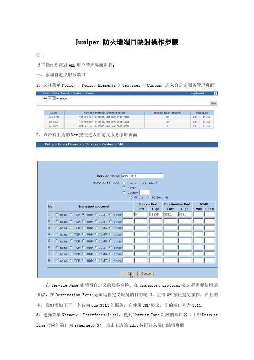
Juniper 防火墙端口映射操作步骤注:以下操作均通过WEB用户管理界面进行:一、添加自定义服务端口1、选择菜单Policy > Policy Elements > Services > Custom,进入自定义服务管理页面2、点击右上角的New按钮进入自定义服务添加页面在Service Name处填写自定义的服务名称,在Transport protocol处选择需要使用的协议,在Destination Port 处填写自定义服务的目的端口,点击OK按钮提交操作。
在上图中,我们添加了了一个名为udp-3311的服务,它使用UDP协议,目的端口号为3311。
3、选择菜单Network > Interfaces(List),找到Untrust Zone对应的端口名(图中Untrust Zone对应的端口为ethernet0/0),点击右边的Edit按钮进入端口编辑页面4、点击Properties中的VIP按钮,切换到VIP管理页面初次添加VIP设置时,如果你有多个外网IP地址,你可以选择填入你的Virtual IP Address,如果ISP只提供给你一个外网IP地址或者你通过PPPOE方式获得外网IP,你可以选择Same as the untrusted interface IP address,点击Add按钮提交。
5、点击New VIP Service按钮,进入VIP服务添加页面6、添加VIP Service相关信息A、在Map to Service 下拉列表中选择现有服务类型或者自定义的服务,图中我们选择了之前添加的udp-3311服务B、在Map to IP中填写提供服务的主机IP,Virtual Port与自定义服务的端口一致,不要勾选Server Auto Detection后Enable选项,点击OK按钮提交7、选择菜单Policy > Policies,进入策略管理页面8、左上角的From选择Untrust Zone,To选择Trust Zone,点击NEW进入From Untrust To Trust策略新增页面Source Address(源地址)从Address Book Entry中选择Any,Destination Address (目的地址)从Address Book Entry中选择相关的VIP服务,Service选择自定义的服务。
常见的几种交换机端口镜像配置详解

常见的几种交换机端口镜像配置详解端口镜像配置之DELL在交换机管理界面左边的树形菜单中,选中“Switch”(交换机)>>>“Ports”(端口)>>>“PortMirroring”(端口镜像),右边将打开“PortMirroring”(端口镜像)页面。
该页面中的参数解释如下:Add(添加):添加端口镜像操作DestinationPort(目的地端口):定义端口通信要镜像到的端口号;SourcePort(源端口):定义被镜像端口的端口号。
最多可以将8个被镜像端口镜像到一个镜像端口;Type(类型):指定要镜像的端口通信类型。
可能的字段值包括:“RX”-表示镜像进入网络的数据;“TX”-表示镜像流出网络的数据;Both()-表示镜像所有数据。
Status(状态):表示端口的状态。
可能的字段值包括:“Active”-表示端口被启用;“NotActive”-表示端口被禁用。
Remove(删除):删除端口镜像会话。
可能的字段值包括:“已选取”-删除端口镜像会话;“未选取”-保留端口镜像会话。
具体端口镜像配置:1.在PortMirroring对话框中的DestinationPort中选中目的端口(端口镜像),再单击Add按钮;2.在系统将打开“AddSourcePort”(添加源端口)页面中,定义“SourcePort”(源端口)和“Type”(类型)字段,并单击“ApplyChanges”(应用更改),使系统接收更改。
(注:如果需要从端口镜像会话删除副本端口,请打开“PortMirroring”(端口镜像)页面,选取“Remove”(删除)复选框,再单击“ApplyChanges”(应用更改)。
系统将删除端口镜像会话,并更新设备。
)以下是CLI命令实例:Console(config)#interfaceethernet1/e1Console(config-if)#portmonitor1/e8Console#showportsmonitorSourceportDestinationPortTypeStatus---------------------------------------1/e11/e8RX,TXActive下面我们来看看具体的几种类型的交换机是如何进行端口镜像配置的:Juniper交换机的端口镜像配置方法JuniperM系列和T系列交换机端口镜像配置方法usen@router#showforwarding-optionsport-mirroring{input{familyinet;rate;run-leng th;}outputinterface{next-hop;}no-filter-check;}}选择将抽样的流量发送到哪个目的端口user@router#showfirewallfiltermirror-samplefrom{…}then{sample;accept;}定义抽样过滤器,选择感兴趣的流量user@router#showinterfaceunit0familyinetfilter{inputmirror-sample;}选择将抽样的过滤器应用到某个端口Nortel8000交换机的端口镜像配置方法Software3.2.0.0以前的版本,支持一组端口镜像,10个source,一个destinationSoftware3.2.0.0后的版本,支持2组镜像,(说明:通常8个ethernet口为一个电路集成板,destination不可以在同一个板子上,即1-8口上只允许有一个destination),支持25个source。
华为镜像配置说明及配置实例

华为镜像说明端口镜像详解什么是端口镜像?把交换机一个或多个端口(VLAN)的数据镜像到一个或多个端口的方法。
为什么需要端口镜像 ?通常为了部署 IDS 产品需要监听网络流量(网络分析仪同样也需要),但是在目前广泛采用的交换网络中监听所有流量有相当大的困难,因此需要通过配置交换机来把一个或多个端口(VLAN)的数据转发到某一个端口来实现对网络的监听。
端口镜像的别名支持端口镜像的交换机大多数中档以上的交换机都支持端口镜像功能,但支持程度不同。
端口镜像配置方法下面是几种交换机的端口镜像配置方法,主要来自于 Talisker Security Wizardry (/) 的 Switch Port Mirroring (/switch.htm)Cisco 交换机特点:Cisco 2900 和 Cisco 3500XL 系列交换机Cisco 2950、Cisco 3550 和 Cisco 3750 系列交换机Cisco catylist 2550 Cisco catylist 3550 支持2组monitor session en password config term Switch(config)#monitor session 1 destination interface fast0/4(1为session id,id范围为1-2) Switch(config)#monitor session 1 source interface fast0/1 , fast0/2 , fast0/3 (空格,逗号,空格) Switch(config)#exit Switch#copy running-conf startup-conf Switch#show port-monitorCisco 5000 系列交换机使用 CatOS 的 Cisco 4000 和 Cisco 6000 系列交换机使用 IOS 的 Cisco 4000 和 Cisco 6000 系列交换机Extreme 交换机特点:●只能创建多对一或者一对一的镜像端口●可以监听 VLAN 的流量●Extreme 会镜像 IN 和 OUT 的流量。
最全的交换机端口镜像整理文档
交换机端口镜像资料收集整理1 端口镜像简介1.1 端口镜像简介镜像一般是将符合指定规则的报文复制到镜像目的端口。
一般镜像目的端口会接入数据检测设备,用户利用这些设备对镜像过来的报文进行分析,进行网络监控和故障排除等。
图1-1 镜像示意图1.1.1 端口镜像的定义端口镜像,即把交换机一个或多个端口(VLAN)的数据镜像到一个或多个端口的方法。
1.1.2 端口镜像的目的通常为了部署 IDS 产品需要监听网络流量(网络分析仪同样也需要),但是在目前广泛采用的交换网络中监听所有流量有相当大的困难,因此需要通过配置交换机来把一个或多个端口(VLAN)的数据转发到某一个端口来实现对网络的监听。
1.1.3 端口镜像的别名端口镜像通常有以下几种别名:Port Mirroring :λ通常指允许把一个端口的流量复制到另外一个端口,同时这个端口不能再传输数据。
Monitoring Port :λ监控端口Spanning Port :λ通常指允许把所有端口的流量复制到另外一个端口,同时这个端口不能再传输数据。
SPAN port :λ在 Cisco 产品中,SPAN 通常指 Switch Port ANalyzer。
某些交换机的SPAN 端口不支持传输数据。
Linkλ Mode port :1.1.4 支持端口镜像的交换机大多数中档以上的交换机都支持端口镜像功能,但支持程度不同。
1.2 端口镜像的类型1.2.1 远程端口镜像远程端口镜像,突破了镜像源端口和镜像目的端口必须在同一台交换机上的限制,使镜像源端口和镜像目的端口可以在不同的网络设备上,从而方便网管人员对远程交换机设备进行管理。
远程端口镜像的应用示意图如下所示。
图1-2 远程端口镜像应用示意图实现了远程端口镜像功能的交换机分为三种:λ源交换机:被监测的端口所在的交换机,负责将镜像流量复制到Remote-probe VLAN中,然后二层转发给中间交换机或目的交换机。
常见的几种交换机端口镜像配置详解(学习资料)
常见的几种交换机端口镜像配置详解端口镜像配置之DELL在交换机管理界面左边的树形菜单中,选中“Switch”(交换机)>>>“Ports”(端口)>>>“PortMirroring”(端口镜像),右边将打开“PortMirroring”(端口镜像)页面。
该页面中的参数解释如下:Add(添加):添加端口镜像操作DestinationPort(目的地端口):定义端口通信要镜像到的端口号;SourcePort(源端口):定义被镜像端口的端口号。
最多可以将8个被镜像端口镜像到一个镜像端口;Type(类型):指定要镜像的端口通信类型。
可能的字段值包括:“RX”-表示镜像进入网络的数据;“TX”-表示镜像流出网络的数据;Both()-表示镜像所有数据。
Status(状态):表示端口的状态。
可能的字段值包括:“Active”-表示端口被启用;“NotActive”-表示端口被禁用。
Remove(删除):删除端口镜像会话。
可能的字段值包括:“已选取”-删除端口镜像会话;“未选取”-保留端口镜像会话。
具体端口镜像配置:1.在PortMirroring对话框中的DestinationPort中选中目的端口(端口镜像),再单击Add按钮;2.在系统将打开“AddSourcePort”(添加源端口)页面中,定义“SourcePort”(源端口)和“Type”(类型)字段,并单击“ApplyChanges”(应用更改),使系统接收更改。
(注:如果需要从端口镜像会话删除副本端口,请打开“PortMirroring”(端口镜像)页面,选取“Remove”(删除)复选框,再单击“ApplyChanges”(应用更改)。
系统将删除端口镜像会话,并更新设备。
)以下是CLI命令实例:1.Console(config)#interfaceethernet1/e12.3.Console(config-if)#portmonitor1/e84.5.Console#showportsmonitor6.7.SourceportDestinationPortTypeStatus8.9.---------------------------------------10.11.1/e11/e8RX,TXActive下面我们来看看具体的几种类型的交换机是如何进行端口镜像配置的:Juniper交换机的端口镜像配置方法JuniperM系列和T系列交换机端口镜像配置方法usen@router#showforwarding-optionsport-mirroring{input{familyinet;rate;run-length;}outputint erface{next-hop;}no-filter-check;}}选择将抽样的流量发送到哪个目的端口user@router#showfirewallfiltermirror-samplefrom{...}then{sample;accept;}定义抽样过滤器,选择感兴趣的流量user@router#showinterfaceunit0familyinetfilter{inputmirror-sample;}选择将抽样的过滤器应用到某个端口Nortel8000交换机的端口镜像配置方法Software3.2.0.0以前的版本,支持一组端口镜像,10个source,一个destinationSoftware3.2.0.0后的版本,支持2组镜像,(说明:通常8个ethernet口为一个电路集成板,destination 不可以在同一个板子上,即1-8口上只允许有一个destination),支持25个source。
华为端口镜像配置

session 1 概述端口镜像原理,将镜像端口的流量复制一份发送到观察端口供观察端口下连的流量分析设备(软件)对复制来的镜像端口的流量进行分析,在华为的SPAN 端口镜像中观察端口仍然可以发送和接受数据(思科中观察端口就会停止正常的数据收发,只能观察从镜像端口复制来的流量)。
一、镜像的分类1、端口镜像端口镜像是基于端口的镜像,分为本地端口镜像、二层远程端口镜像、三层远程端口镜像,镜像的流量可以是入向或者出向。
2、流镜像流镜像是基于流的镜像,是根据用户配置的刘策略traffic-class匹配的流量进行镜像,只支持(镜像端口的)入方向,不支持出方向。
流镜像分为本地流镜像、二层远程流镜像、三层远程流镜像。
3、vlan镜像vlan镜像是基于vlan的镜像,是将制定的vlan内的所有活动接口的入方向的流量复制到观察端口,不支持出方向。
vlan镜像分为本地vlan镜像、二层远程vlan 镜像。
4、mac地址镜像基于mac地址的镜像,将匹配源或目的的mac地址的入方向的流量复制到观察关口,不支持出方向。
mac地址镜像支持本地mac地址镜像、二层远程mac地址镜像。
session 2 镜像的配置一、端口镜像配置1、本地端口镜像配置[Huawei]observe-port 1 interface g0/0/1 配置一个序列号为1的观察端口g0/0/1[Huawei]interface g0/0/2 配置镜像端口[Huawei-GigabitEthernet0/0/2]port-mirroring to observe-port 1 both 配置一个镜像端口,将双向流量复制到序列号为1的观察端口[Huawei-GigabitEthernet0/0/2]quit查看端口配置状态[Huawei]display observe-port----------------------------------------------------------------------Index : 1Interface: GigabitEthernet0/0/1Used : 2----------------------------------------------------------------------[Huawei][Huawei]display port-mirroringPort-mirror:----------------------------------------------------------------------Mirror-port Direction Observe-port----------------------------------------------------------------------GigabitEthernet0/0/2 Both GigabitEthernet0/0/1----------------------------------------------------------------------[Huawei]2、二层远程端口镜像端口的二层远程镜像的原理是通过创建一个vlan,将镜像端口的流量复制到观察端口中,观察端口在该vlan中进行广播,通过vlan的广播将复制的流量发送到监控设备连接的端口上,进行监控。
神州数码交换机端口镜像设置命令
神州数码交换机端口镜像设置神码3526S/3926S指定镜像源端口:Switch(Config)#monitor session 1 source interface e 1,2-4 0/0/2-4txSwitch(Config)#monitor session<session> source interface e 端口列表{tx,rx,both}rx为镜像源端口接收的流量;tx为镜像从源端口发出的流量;both为源端口入和出的流量。
指定镜像目的端口;Switch(Config)# monitor session 1 destination interface eth 250/0/25为3926端口Switch(Config)#monitor session <session> destination interface <interface-number>其他配置型号端口镜像命令:[no] mirror-port ethernet <portnum>功能:激活镜像端口命令模式:特权配置模式参数:<portnum>为镜像端口的端口号命令:[no] monitor ethernet <portnum> [ethernet <portnum>...] both | in | out功能:激活被镜像的端口的镜像功能命令模式:端口配置模式参数:<portnum>为镜像端口端口号;both | in | out分别代表双向流量,输入流量,输出流量举例一:DCRS-7500(config)# mirror-port ethernet 4/1DCRS-7500(config)# interface ethernet 4/3DCRS-7500(config-if-4/3)# monitor ethernet 4/1 both上述命令将端口4/3上的双向流量镜像到端口4/1,用户可以在端口4/1外接协议分析仪来查看端口4/3的流量信息。
Juniper交换机中文操作手册(完整版)V1.0

Juniper EX 系列以太网交换机操作手册Version 1.0Copyright © 2008 Juniper Networks, Inc.Juniper EX系列以太网交换机操作手册Juniper EX系列以太网交换机操作手册Juniper EX系列以太网交换机操作手册Juniper EX系列以太网交换机操作手册Juniper EX系列以太网交换机操作手册Juniper EX系列以太网交换机操作手册Juniper EX系列以太网交换机操作手册Juniper EX系列以太网交换机操作手册Juniper EX系列以太网交换机操作手册Juniper EX系列以太网交换机操作手册Juniper EX系列以太网交换机操作手册Juniper EX系列以太网交换机操作手册Juniper EX系列以太网交换机操作手册Juniper EX系列以太网交换机操作手册Juniper EX系列以太网交换机操作手册Juniper EX系列以太网交换机操作手册Juniper EX系列以太网交换机操作手册Juniper EX系列以太网交换机操作手册Juniper EX系列以太网交换机操作手册Juniper EX系列以太网交换机操作手册Juniper EX系列以太网交换机操作手册Juniper EX系列以太网交换机操作手册Juniper EX系列以太网交换机操作手册Juniper EX系列以太网交换机操作手册Juniper EX系列以太网交换机操作手册Juniper EX系列以太网交换机操作手册Juniper EX系列以太网交换机操作手册Juniper EX系列以太网交换机操作手册Juniper EX系列以太网交换机操作手册Juniper EX系列以太网交换机操作手册Juniper EX系列以太网交换机操作手册Juniper EX系列以太网交换机操作手册Juniper EX系列以太网交换机操作手册Juniper EX系列以太网交换机操作手册Juniper EX系列以太网交换机操作手册Juniper EX系列以太网交换机操作手册Juniper EX系列以太网交换机操作手册Juniper EX系列以太网交换机操作手册Juniper EX系列以太网交换机操作手册Juniper EX系列以太网交换机操作手册Juniper EX系列以太网交换机操作手册Juniper EX系列以太网交换机操作手册Juniper EX系列以太网交换机操作手册Juniper EX系列以太网交换机操作手册Juniper EX系列以太网交换机操作手册Juniper EX系列以太网交换机操作手册Juniper EX系列以太网交换机操作手册Juniper EX系列以太网交换机操作手册Juniper EX系列以太网交换机操作手册。
端口镜像如何配置(H3C部分)---华为产品与技术

S3100系列交换机system-view[H3C] mirroring-group 1 local[H3C] mirroring-group 1 monitor-port Ethernet 1/0/4[H3C] mirroring-group 1 mirroring-port Ethernet 1/0/1 bothS3600系列交换机在端口视图下配置1:system-view[H3C] mirroring-group 1 local[H3C] interface gigabitEthernet 1/1/4[H3C-GigabitEthernet1/1/4] monitor-port[H3C-GigabitEthernet1/1/4] quit[H3C] interface gigabitEthernet 1/1/1[H3C-GigabitEthernet1/1/1] mirroring-port both在端口视图下配置2:创建端口镜像组system-view[H3C] mirroring-group 1 local[H3C] interface GigabitEthernet 1/1/4[H3C-GigabitEthernet1/1/4] mirroring-group 1 monitor-port[H3C-GigabitEthernet1/1/4] quit[H3C] interface GigabitEthernet 1/1/1[H3C-GigabitEthernet1/1/1] mirroring-group 1 mirroring-port both在系统视图下配置1、创建端口镜像组<H3C>system-view[H3C] mirroring-group 1 local2、配置镜像目的端口。
[H3C] mirroring-group 1 monitor-port GigabitEthernet 1/1/43、配置镜像源端口,同时指定被镜像报文的方向。
Juniper EX交换机端口镜像配置

Example: Configuring Port Mirroring for Local Monitoring of Employee Resource Use on EX Series SwitchesEX Series switches allow you to configure port mirroring to send copies of packets to either a local interface for local monitoring or to a VLAN for remote monitoring. You can use port mirroring to copy these packets:•Packets entering or exiting a port•Packets entering a VLAN on EX2200, EX3200, EX4200, or EX4500 switches•Packets exiting a VLAN on EX8200 switchesYou can analyze the mirrored traffic using a protocol analyzer application installed ona system connected to the local destination interface (or a running on a remotemonitoring station if you are sending mirrored traffic to an analyzer VLAN).This example describes how to configure an EX Series switch to mirror trafficentering interfaces connected to employee computers to an analyzer output interface on the same switch.This example describes how to configure local port mirroring:RequirementsThis example uses the following hardware and software components:•Junos OS Release 9.0 or later for EX Series switches•One EX Series switchBefore you configure port mirroring, be sure you have an understanding of portmirroring concepts.Overview and TopologyThis topic includes two related examples that describe how to mirror traffic entering ports on the switch to a destination interface on the same switch. The first example shows how to mirror all traffic entering the ports connected to employee computers.The second example shows the same scenario, but includes a filter to mirror only the employee traffic going to the Web.In this example, ge-0/0/0 and ge-0/0/1 serve as connections for employeecomputers.In this example, one interface, ge-0/0/10, is reserved for analysis of mirrored traffic. Connect a PC running a protocol analyzer application to the analyzer output interfaceto analyze the mirrored traffic.Note: Multiple ports mirrored to one interface can cause buffer overflow and dropped packets. Figure 1 shows the network topology for this example.Figure 1: Network Topology for Local Port Mirroring ExampleMirroring All Employee Traffic for Local AnalysisTo configure port mirroring for all employee traffic for local analysis, perform these tasks:CLI Quick ConfigurationTo quickly configure local port mirroring for ingress traffic to the two ports connectedto employee computers, copy the following commands and paste them into the switch terminal window:[edit]set interfaces ge-0/0/0 unit 0 family ethernet-switchingset interfaces ge-0/0/1 unit 0 family inet 192.1.1.1/24set interfaces ge-0/0/10 unit 0 family ethernet-switchingset ethernet-switching options analyzer employee–monitor input ingress interface ge-0/0/0.0set ethernet-switching options analyzer employee–monitor input ingress interface ge-0/0/1.0set ethernet-switching options analyzer employee–monitor output interface ge-0/0/10.0Step-by-Step ProcedureTo configure an analyzer called employee-monitor and specify the input (source) interfaces and the analyzer output interface:1.Configure each interface connected to employee computers as an input interface for the port-mirror analyzer thatwe are calling employee-monitor:[edit ethernet-switching-options]user@switch# set analyzer employee-monitor input ingress interface ge–0/0/0.0user@switch# set analyzer employee-monitor input ingress interface ge–0/0/1.02.Configure the output analyzer interface for the employee-monitor analyzer. This will be the destinationinterface for the mirrored packets:[edit ethernet-switching-options]user@switch# set analyzer employee-monitor output interface ge-0/0/10.0ResultsCheck the results of the configuration:[edit]user@switch# show ethernet-switching-options {analyzer employee-monitor {input {ingress {interface ge-0/0/0.0;interface ge-0/0/1.0;}}output {interface {ge-0/0/10.0;}}}}Mirroring Employee-to-Web Traffic for Local AnalysisTo configure port mirroring for employee to web traffic, perform these tasks:CLI Quick ConfigurationTo quickly configure local port mirroring of traffic from the two ports connected to employee computers, filtering so that only traffic to the external Web is mirrored, copy the following commands and paste them into the switch terminal window:[edit]set ethernet-switching-options analyzer employee–web–monitor output interface ge-0/0/10.0set firewall family ethernet-switching filter watch-employee term employee-to-corp fromdestination-address 192.0.2.16/28set firewall family ethernet-switching filter watch-employee term employee-to-corp from source-address 192.0.2.16/28set firewall family ethernet-switching filter watch-employee term employee-to-corp then acceptset firewall family ethernet-switching filter watch-employee term employee-to-web fromdestination-port 80set firewall family ethernet-switching filter watch-employee term employee-to-web then analyzer employee-web-monitorset interfaces ge-0/0/0 unit 0 family ethernet-switching filter input watch-employeeset interfaces ge-0/0/1 unit 0 family ethernet-switching filter input watch-employeeStep-by-Step ProcedureTo configure local port mirroring of employee-to-web traffic from the two portsconnected to employee computers:1.Configure the local analyzer interface:[edit interfaces]user@switch# set ge-0/0/10 unit 0 family ethernet-switching2.Configure the employee-web-monitor analyzer output (the input to the analyzer comes from the action ofthe filter):[edit ethernet-switching-options]user@switch# set analyzer employee-web-monitor output interface ge-0/0/10.03.Configure a firewall filter called watch-employee to send mirrored copies of employee requests to the Webto the employee-web-monitor analyzer. Accept all traffic to and from the corporate subnet (destination or source address of 192.0.2.16/28). Send mirrored copies of all packets destined for the Internet(destination port 80) to the employee-web-monitor analyzer.[edit firewall family ethernet-switching]user@switch# set filter watch-employee term employee-to-corp from destination-address 192.0.2.16/28user@switch# set filter watch-employee term employee-to-corp from source-address192.0.2.16/28user@switch# set filter watch-employee term employee-to-corp then acceptuser@switch# set filter watch-employee term employee-to-web from destination-port 80user@switch# set filter watch-employee term employee-to-web then analyzer employee-web-monitor4.Apply the watch-employee filter to the appropriate ports:[edit interfaces]user@switch# set ge-0/0/0 unit 0 family ethernet-switching filter input watch-employeeuser@switch# set ge-0/0/1 unit 0 family ethernet-switching filter input watch-employeeResultsCheck the results of the configuration:[edit]user@switch# show ethernet-switching-options {analyzer employee-web-monitor {output {interface ge-0/0/10.0;}}}...firewall family ethernet-switching {filter watch-employee {term employee-to-corp {from {destination-address 192.0.2.16/28;source-address192.0.2.16/28;}then accept {}term employee-to-web {from {destination-port 80;}then analyzer employee-web-monitor;}}}...interfaces {ge-0/0/0 {unit 0 {family ethernet-switching {port-mode trunk;vlan members [employee-vlan, voice-vlan];filter {input watch-employee;}}}}ge-0/0/1 {family ethernet-switching {filter {input watch-employee;}}}}VerificationTo confirm that the configuration is correct, perform these tasks:Verifying That the Analyzer Has Been Correctly CreatedPurposeVerify that the analyzer named employee-monitor or employee-web-monitor has been created on the switch with the appropriate input interfaces, and appropriate output interface.ActionYou can verify the port mirror analyzer is configured as expected using the show analyzer command.user@switch> show analyzerAnalyzer name : employee-monitorOutput interface : ge-0/0/10.0Mirror ratio : 1Loss priority : LowIngress monitored interfaces : ge-0/0/0.0Ingress monitored interfaces : ge-0/0/1.0Egress monitored interfaces : NoneMeaningThis output shows that the employee-monitor analyzer has a ratio of 1 (mirroring every packet, the default setting), a loss priority of low (set this option to high only when the analyzer output is to a VLAN), is mirroring the traffic entering the ge-0/0/0 and ge-0/0/1 interfaces, and sending the mirrored traffic to the ge-0/0/10interface.。
端口镜像详解及配置

端口镜像详解及配置什么是端口镜像?把交换机一个或多个端口(VLAN)的数据镜像到一个或多个端口的方法。
为什么需要端口镜像 ?通常为了部署IDS 产品需要监听网络流量(网络分析仪同样也需要),但是在目前广泛采用的交换网络中监听所有流量有相当大的困难,因此需要通过配置交换机来把一个或多个端口(VLAN)的数据转发到某一个端口来实现对网络的监听。
端口镜像的别名端口镜像通常有以下几种别名:●Port Mirroring通常指允许把一个端口的流量复制到另外一个端口,同时这个端口不能再传输数据。
●Monitoring Port监控端口●Spanning Port通常指允许把所有端口的流量复制到另外一个端口,同时这个端口不能再传输数据。
●SPAN port在 Cisco 产品中,SPAN 通常指 Switch Port ANalyzer。
某些交换机的 SPAN 端口不支持传输数据。
●Link Mode port支持端口镜像的交换机和路由大多数中档以上的交换机都支持端口镜像功能,部分路由支持端口镜像但支持程度不同。
端口镜像配置方法下面是几种交换机和海蜘蛛路由端口镜像配置方法,主要来自于Talisker Security Wizardry (/) 的Switch Port Mirroring(/switch.htm)Cisco 交换机特点:●Cisco 2900 和 Cisco 3500XL 系列交换机Cisco 2950、Cisco 3550 和 Cisco 3750 系列交换机Cisco catylist 2550 Cisco catylist 3550 支持2组monitor session en password config termSwitch(config)#monitor session 1 destination interface fast0/4(1为session id,id范围为1-2)Switch(config)#monitor session 1 source interface fast0/1 , fast0/2 , fast0/3 (空格,逗号,空格)Switch(config)#exitSwitch#copy running-conf startup-confSwitch#show port-monitorCisco 5000 系列交换机使用 CatOS 的 Cisco 4000 和 Cisco 6000 系列交换机使用 IOS 的 Cisco 4000 和 Cisco 6000 系列交换机Extreme 交换机特点:●只能创建多对一或者一对一的镜像端口●可以监听 VLAN 的流量●Extreme 会镜像 IN 和 OUT 的流量。
交换机端口镜像配置大全【汇集22个各种品牌交换机】

交换机端⼝镜像配置⼤全【汇集22个各种品牌交换机】1、思科(CISCO)交换机1.1配置镜像(SPAN)端⼝Switch(config)# monitor session 1 source interface fastethernet 4/10Switch(config)# monitor session 1 filter vlan 57Switch(config)# monitor session 1 destination interface fastethernet 4/15如果想释放该SPAN 任务,输⼊如下命令:Switch(config)# no monitor session 1以下语句显⽰如何检验SPAN 任务的配置结果:Switch# show monitor session 2在配置镜像端⼝(SPAN)过程中,还应考虑到数据流量过⼤时,设备的处理速度及端⼝数据缓存的⼤⼩,要尽量减少被监控数据包的丢失。
1.2 Catalyst 2550/2950/3550/3560/3560-E/3570-E旧交换机系统命令:Switch(config)# int fa0/1Switch(config-if)# port monitor fastEthernet0/2新交换机系统命令:Switch> show interfacesSwitch> enablePassword: ciscoSwitch# configure terminalSwitch(config)# monitor session 1 source interface fastethernet 0/17Switch(config)# monitor session 1 destination interface fastethernet 0/2Switch(config)# endSwitch# show monitor session 1 --查看镜像Switch# no monitor session 1 --清空镜像Switch# show running-config --查看运⾏配置Switch# copy running-config startup-config --保存到配置⽂件如果⽤ display mirror 命令看到ingress:disabled,说明划分了VLAN,源数据中包含了⽬的端⼝所在的VLAN。
