给XP系统加油:让运行提速100%
力普LP100说明书PDF

12
FOR REV JOG FRE SP1 SP2 SP3
RST
ST1 ST2 COM OT1 OT2
24V
TC TB TA
第四章 安装规范
正转 反转 点动 保留
端子控制模式下,正转输入指令 端子控制模式下,反转输入指令 点动输入指令,默认正转
多段速 1~3
三个端子组合成 1~7 段速输入指 令
复位
(
率 给 定 电 流 信 号
拟 信 号 地
(
馈 输 入 电 压 信 号
(
馈 输 入 电 流 信 号
率 表 输 出
正 转
反 转
控 制 信 号 地
点 动
保 留
多 段 速
多 段 速
多 段 速
复 位
加 减 速 时 间 选 择
加 减 速 时 间 选 择
行 频 率 水 平 检 测
行 频 率 水 平 检 测
制 辅 助 电 源
设备中断
频率给定
键盘、键盘电位器、端子 VA(0~5V、0~10V)端 子 IA(0~20mA、4~20mA)
反馈输入
端子 VF(0~5V、0~10V)、
运
端子 IF(0~20mA、4~20mA)
行
运行指令信号
正转、反转、点动
输出信号
故障继电器输出 2A/240VAC 辅助控制信号 OT1、OT2(开集电极输出) 频率表输出(0~5V)
LP-100G-7R5(B)
公司缩写 开发序列
注:铭牌在机箱右侧。
系列标示 G:泛用型
内置制动单元 输出容量
2
第二章 标准规范
二、LP-100G 系列额定输出一览表
型号
电压等级(V) 功率(kW)
佳能iP100详细参数

400-622-2666纠错
电话备注
周一至周五:9:00-20:00;周六和周日:9:00-18:00(节假日休息)纠错
详细内容
佳能支持全国联保,可享有三包服务。若按使用说明和操作指南正常使用情况下,本品发生故障,您可查询最近的维修点,由厂商售后解决。也可凭厂商维修中心或特约维修点所提供的质量检测证明,享受7日内退货,15日内换货。超过15日又在质保期内,可享受免费保修等三包服务政策,产品的保修起始日期以购机发票标明的购机日期为准。进入官网>>纠错
最小墨滴
1pl纠错
喷头配置
共1856个喷嘴(青色/品红256×4个,染料黑色/黄色256×2个,颜料黑色320个)纠错
其它参数
产品尺寸
322×185×61.7mm纠错
产品重量
约2kg纠错
系统平台
Windows Vista/ XP/2000
Mac OS X v.10.5/X v.10.4/ X v.10.3.9纠错
T恤转印介质(TR-301):1
信封:European DL and US Com. #10=10纠错
耗材
墨盒类型:一体式墨盒纠错
墨盒数量:五色墨盒纠错
墨盒型号:黑色颜料PGI-35,彩色染料CLI-36纠错
墨水容量:彩色文档(A4):黑色颜料191页,彩色染料249页
照片(4"×6"):黑色颜料2080页,彩色染料112页纠错
介质尺寸
A4,Letter,Legal,A5,B5,Envelopes(DL,COM10),4×6",5×7",8"x10",信用卡,Wide纠错
介质重量
普通纸:64-105g/m²,特殊纸:大约273g/m²纠错
IPS100使用手册

目录目录 (1)第一章前言 (3)第二章关于本产品 (4)关于IPS100 (4)本产品的使用环境 (4)包装内容 (4)各部件的名称和功能 (5)接口 (5)指示灯 (5)复位按键 (6)系统出厂配置 (6)第三章安装方法 (7)准备 (7)连接打印机 (7)连接网络线 (7)通电并检查指示灯 (7)管理员软件安装 (8)普通用户软件安装 (10)软件卸载 (12)第四章在Windows环境下进行网络打印 (13)在Windows 2000/XP 环境下用TCP/IP 协议打印 (13)确认PC的网络设置 (13)设置本产品 (14)搜索 (14)选择 (15)设置IP地址 (15)确认 (16)使用RAW方式进行打印 (17)使用LPR方式进行打印 (24)使用SMB方式进行打印 (28)使用IPP方式进行打印 (31)第五章使用打印服务器管理工具 (33)系统要求 (33)软件安装 (33)软件操作 (33)第六章使用打印机状态监视工具 (43)软件安装 (43)软件操作 (43)第七章使用WWW浏览器 (45)启用WWW浏览器 (45)常规 (46)设置 (48)信息 (52)第八章常见问题及故障维修 (55)第一章 前言感谢您购买本公司的网络打印服务器。
这本使用手册详细地记述了本产品的设置及使用方法。
为了正确使用本产品,请仔细阅读本手册并注意保管。
本产品是10BASE-T/100BASE-T 自适应打印服务器,主要以TCP/IP (WindowsXP,Windows2000)协议为基础,实现多种网络打印服务协议。
本手册将指导使用的顾客如何设置并使用本产品。
【使用本手册的注意事项】未经本公司的许可,本使用手册不得转载或复制。
一经发现,将追究法律责任。
今后本使用手册内容变更时不再预告。
本使用手册本着尽全尽善宗旨编辑。
对于所使用的设置实例结果,本公司不负责任。
有关本产品的问题请与芯彩科技联系,芯彩科技全程服务热线电话:010-8289-6060。
KPX 100可编程密码键盘指南说明书

∙∙∙∙D.A.P. Reset seePage 5∙∙∙∙∙∙∙∙∙????#*This must be done after DAP resetRecord the new code0 0 0 0*Set system into programming mode with factory set master code.8 9 0 0 8 9 0 1 # #Set system to single user mode, clear all previous data & refreshes system Set system to multi user mode, clear all previous data & refreshes system4 0 4 1 4 2 1 to 999# # # Output 1 in momentary mode from 1 to 999 seconds Output 1 in Start / Stop Mode (toggle) Output 1 in Start / Stop Mode (toggle) with accelerated code5 0 5 1 5 21 to 999 # # #Output 2 in momentary mode from 1 to 999 seconds Output 2 in Start / Stop Mode (toggle) Output 2 in Start / Stop Mode (toggle) with accelerated code0 2# # #4 digits, fixed 4 digits, fixed 4 digits, fixedPersonal Master Code & Super User CodeUser Code 1 for output 1 with Duress Code function User code 2 for output 21 Personal Master Code & Super User Code # 100 User codes in Group 1 for output 1 with Duress Code function0 1 2 00 to 99 0 to 94 to 8 digits4 to 8 digits 4 to 8 digits10 User Codes in Group 2 for output 2##i)ii)7 0 7 1 7 27 6 5 to 1000 # # ##After 10 successive false codes, keypad will lock for 30 secondsAfter 10 successive false codes, the Duress output switches to groundSelectable from 5 to 10 successive false codes, the keypad locks for 15 minutes. The keypad can be reset to release lock with the Master Code at any time during the locking period. Removal of all above security settings8 0 8 0 # #1 0Door Forced Open Alarm is Activated Door Forced Open Alarm is Disabled8 11 #1 second notification beep is given to notify the person outside to open the door when output relay is activated with a user code or egressbutton. Good for the locking device that gives no sound when it activates, such as magnetic lock. 8 1 0 #Notification beep disabled and replaced by 2 short successful code entry beeps for valid user codes.8 2 1 #Auto Entry Mode is selected. Key that followsthe user code is not required in code entry. The usercodes must be set in the same digit length as theMaster Code in Auto Entry mode and the code can be 4-8 digits82#Manual Entry Mode is selected. Key that followsthe user code is required in code entry. The user codescan be 4-8 digits and are not required to be the samelength as the Master Code.##8 3 8 3 1 0# #Tones are active on key pressTones are off. Use for silent environment requirements9 9# #No Propped Open AlarmTime from 1 to 999 seconds until door propped open activates alarm0 1 to 999*Keypad exits programming mode and returns to normal operationMASTER CODE*8 9 0 0#MASTER CODE*891#*MASTER CODE*LOCATION 1#OPTIONLOCATION n#OPTION n*0 0 0 0 * ----------- 8 9 0 0 # -----------0 3 2 8 9 1 8 3 2 1 # # --- --- 2 6 8 5 4 # ---4 0 1#Output 1 has been set to momentary mode with 1 second duration5 1 # ------------------- O utput 2 has been set to Start / Stop (toggle) mode7 21 0# ---------* ----------------------------*#8321685 4------------------ Output 1 activates for 1 secondOutput 2 Starts or Stops (toggle mode)#83 2 1 --------- Output 1 activates for 1 second 8 3 2 1--------- Output 2 Starts or Stops (toggle mode)# # 1 2 0 3 2 1--------- Duress output activates (output switches to (-) ground) & Output 1activates for 1 second8 3 #8 3 2 1--------- --------- Output 1 starts Output 1 stops3 2 8 9---------Lockout is reset and keypad resumes normal operation#0 0 0 0 --------- System is set to programming mode using factory set Master User Code * 8 9 0 1 --------- System is set to Multi-User Mode *8 (see note (a) below#0 3 2 8 -------- 3289 has been stored as the new Personal Master Code & Super User Code# 9 1 8 3 2 -------- 8321 has been stored as 1st user code in Group 1 with duresscode function# 1 0 11 3 32 --------33221 has been stored as 3rd user code in Group 1 withduress code function# 2 0 3 1 2 6 8 -------- 6854 has been stored as 1st user code in Group 2# 5 1 4 2 5 4 3 -------- 54321 has been stored as 2nduser code in Group 2#2 2 1 4 ---------------------------- Output 1 is set to Momentary Mode with 1 second duration#0 1 5 --------------------------------- Output 2 is set to Toggle Mode#1 7 ------------------------- Keypad is set to lock for 15 minutes after 10 successive falsecodes# 21 0* -----------------------------------##8 3 2 1 # ----------------------------------- Output 1 activates for 1 second1 12 1 # ------------------------------- Output 1 activates for 1 second3 3 3 2 2 # ------------------------------- Output 1 activates for 1 second1#6 8 5 4 # ----------------------------------- Output 2 Starts or Stops (toggle mode)5 4 3 2 Output 2 Starts or Stops (toggle mode)1#-------------------- 1 1 1 2 --------11223 has been stored as 2nd user code in Group 1 withduress code function# 2 0 2 3#------------------------------- 0 3 2 1 # --- Duress output activates (switches to ground) & Output 1 activates for 1 second3 1 2 2 # ---D uress output activates 9 switches to ground) & Output 1 activates for 1 second 3 5 3 2 2 # ---D uress output activates 9 switches to ground) & Output 1 activates for 1 second 18 3 #8 3 2 1 -------------------- ------------- Output 1 starts Output 1 StartsOutput 1 Stops1 1Output 1 Starts1 12 2---------Output 1 Stops3###3 2 8 9 # ------------------------------- Output 1 activates for 1 second 1 3 2 8 9# ------------------------------- Output 2 Starts or Stops (toggle mode)23 2 8 9 --------- Lockout is reset and keypad resumes normal operation#* *3 2 8 9 --------- Keypad is now in Programming Mode#1 0 5 #2 3 #*∙∙∙∙∙∙∙∙∙∙∙∙(B) DOOR SENSa) Door Auto Relock – the system willimmediately re-lock the door after a validaccess has been gained to prevent “tailgate”entry.b) Door Forced-open alarm – The keypad willgenerate an instant alarm if the door isforced to open. Enable the function withProgram Option 801c) Door Propped Open Alarm – The keypadwill generate an alarm if the door is leftopen longer than the pre-set time. Enablethe function with Program Option 9 withduration of 1 to 999 seconds.With the help of a normally closed door d) Inter-lock Control – When the door is open Position sensor (usually a magnetic door the inter-lock output of the keypad will give switch) o n the door to set up the following a (-) command to de-activate the other functions. keypad in an inter-lock system.∙∙∙∙。
explorer 100 用户指南说明书

Explorer 100 系列用户指南内容盒中物品3耳机概述4配对5设备配对5配对模式5基础知识6应答或结束通话6调整音量6静音6重拨6语音控制6选择语言6配对模式6充电和佩戴调整7充电7调节佩戴方式7耳机功能8音乐及更多内容8指示灯解读8语音提示8DeepSleep 模式8安装应用程序8规格9支持10车载通风口夹*车载电源充电器* 2 合 1 组合电缆*微型 USB 线缆*可选耳套注*配件可能因产品不同而不同。
盒中物品通话按钮充电端口耳机 LED(指示灯)电源按钮调大音量调小音量上一首下一首播放/暂停静音耳机概述第一次开启耳机,耳机就会进入配对模式。
1滑动开启电源开关。
您将听到“pairing ”(正在配对),且指示灯 会呈红灯和蓝灯交替闪烁。
2激活电话上的蓝牙®并将其设置为搜索新设备。
•iPhone 设置 > 蓝牙 > 开启*•Android 设置 > 蓝牙:开启 > 扫描设备*注* 菜单可能因设备不同而不同。
3选择“PLT E100 Series 。
”如有必要,输入密码四个零 (0000) 或接受连接。
配对成功后,您将听到“pairing successful ”(配对成功),且指示灯会停止闪烁。
佩戴耳机,然后打开电源。
按住通话pairing ”(正在配对)。
您的耳机最多可与 2 台设备配对。
配对设备配对配对模式轻触通话轻触音量增加 或音量减小 按钮。
通话期间,同时按住音量增加 和音量减小 按钮 2 秒钟,直至听到“mute on ”(静音开)或“mute off ”(静音关)。
按钮可呼叫您上次拨打的号码。
Siri 、Google Now ™、Cortana按钮 2 秒钟,等待手机提示,以激活语音拨号、搜索和其他智能手机语音控件。
同时按住音量增加 和音量减小 按钮,直至听到“welcome ”(欢迎)。
遵循语音提示来选择耳机语言。
*注*欧洲、俄罗斯和非洲不提供语言选择。
IP-100C
8 P
在监测画面上,在 W2 的时间内显示实际所流通的通电时间。(中途有停止通
电输入时,显示实际的通电时间。)
)&"5 Q
在监测画面上,显示第一段焊接电流的测定值。
ʻ(0ʼʗʻ/(ʼʗʻˎˎʼɿ监测平均值 或者 ʦ(0ʧʗʦ/(ʧʗʦˎˎʧɿ监测峰值(※) (只在监测画面显示)
有水洒出会破坏绝缘,造成漏电和火灾。 请不要覆盖毛毯、布等
使用中请不要覆盖毛毯和布等,可能会因加热而起火。
请不要将此装置用于焊接以外的用途 在指定的使用方法以外的场合使用时,可能会造成触电和起火。
请使用防音保护工具 大噪音会导致听力异常。
请配备灭火器 请在设置本装置的场所内放置灭火器,以防万一。
̍
安全上的注意
ʂ ҙ
使用前,请仔细阅读此ň安全上的注
意ʼnɼҎศਖ਼确༻ຊஔɻ
操作错误时,有可能会导致人受伤以及物品 受损的危险。
˙ 这里所记载的注意事项,都是为了安全
使用本装置,防止对使用者及他人造ة
损 伤 తɻ
这 ࠣੋ༩҆શ༗关 తॏཁ༰ɼҼࠑ请
首先对贵公司购买米亚基公司的逆变式焊接电源IP-100C/200C表示衷心地感谢。
ɾ 此「说明书」记载了IP-100C/200C的操作方法及使用上的注意事项。 ɾ 使用前,请仔细阅读此「使用说明书」以便正确使用。
另外,为了随时可以看,阅读后请妥善保管此说明书。 H06M0665-04
使用注意事项
使用起膊器的人员请不要接近 使用心脏起膊器的人员,除非得到医生的许可,否则请不要接近操作中的焊接机、 焊接作业场所。 焊接机通电中会产生磁场,影响起膊器的正常工作。
HP ProLiant 服务器 ILO 100 配置以及使用
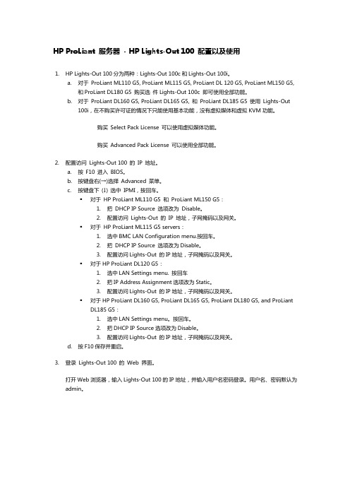
硬件要求:
对于 ProLiant ML110 G5, ProLiant ML115 G5, ProLiant DL 120, ProLiant ML150 G5, ProLiant DL180 G5 购买选件 Lights-Out 100c 可以虚拟 KVM 和虚拟 KVM 功 能。
对于 ProLiant DL160 G5, ProLiant DL165 G5, ProLiant DL185 G5 使用 Lights-Out 100i, 购买 Select Pack License 可以使用虚拟媒体功能。 购买 Advanced Pack License 虚拟媒体和虚拟 KVM 功能。
o
Monitoring Sensors 监控传感器。可以监控服务器温度,风扇和电压。
点击右侧的 PEF 按钮,可以选择需要监控的单元。
o
System Event Log
系统事件日志。记录服务器的事件日志,包括事件的类型,日期,时间,发生源,描述和趋向。
o
Virtual KVM/Media 虚拟 KVM/媒体
o
Network Settings 网络设置。设置访问 LO100 的 IP 地址。
o
IMPI PET Configuration IPMI 事件触发陷阱设置。设置事件日志的触发条件和报警规则。
o
Application License Key 应用许可证密钥。许可证的输入界面。
o
Security Settings 安全性设置。设置 LO100 的访问安全性,提供个人证书验证和密码验证两种方式。
对于 HP ProLiant ML115 G5 s DL120 G5: 1. 2. 3.
PhiClock PCIe 9FGV1001、9FGV1002、9FGV1004 芯片评估板用户指南

EVK9FGV1001EVK9FGV1002EVK9FGV1004IntroductionThe evaluation board is designed to help the customer evaluate the 9FGV1001, 9FGV1002, and 9FGV1004 devices. When the board is connected to a PC running IDT Timing Commander ™ software through USB, the device can be configured and programmed to generate different combinations of frequencies.Board OverviewUse Figure 1 and Table 1 to identify: power supply jacks, USB connector, input and output frequency SMA connectors.Figure 1. Evaluation Board Overview10111213101234567899FGV1001, 9FGV1002, and 9FGV1004 PhiClock™ PCIe Evaluation BoardUser Guide9FGV1001, 9FGV1002, and 9FGV1004 PhiClock™ PCIe Evaluation Board User GuideBoard Power SupplyThe evaluation board uses jumpers E1–E6 to set the power supply voltages for various V DD pins. The 4-way jumpers can select 3 different voltages from regulators that use power from the USB port. Selection #2 is the jack for connecting a bench power supply.E1: Power supply for the REF outputs. The E1 voltage also determines the LVCMOS output levels of the REF0 and REF1 outputs.E2: Power supply for the OUT0 output driver.E3: Power supply for the OUT1 output driver.E4: Power supply for the analog (V DDA ) and digital (V DDD ) core V DD pins.E5: Power supply for the OUT2 output driver.E6: Power supply for the OUT3 output driver.See 9FGV100x Evaluation Board Schematics (Figure 5–Figure 8) for detailed information.Table 1. Evaluation Board Pins and FunctionsLabel NumberNameOn-board Connector LabelFunction1I2C Interface ConnectorJ2Alternative I 2C interface connector for Aardvark.IDT Timing Commander can also use Aardvark.2USB Connector J6Connect this USB to your PC to run IDT Timing Commander.The board can be powered from the USB port.3Output Power Supply Jack J3Connect to 1.8V, 2.5V or 3.3V for the output voltage of the device.4Core Power Supply JackJ4Connect to 1.8V, 2.5V or 3.3V for the core voltage of the device.5Ground Jack J5Connect to ground of power supply.6Differential Output 1S7 and S10Can be a differential pair, or two single-ended outputs.Available logic types: LVCMOS, LVDS and LP-HCSL.7Differential Output 2S6 and S9Can be a differential pair, or two single-ended outputs.Available logic types: LVCMOS, LVDS and LP-HCSL.8Differential Output 3S5 and S8Can be a differential pair, or two single-ended outputs.Available logic types: LVCMOS, LVDS and LP-HCSL.9Reference Output 0S1Reference or buffered output from the crystal.10Power Supply VoltageSelector E1, E2, E3, E4, E5, E6VDD_REFP1, VDDO_0, VDDO_1, four-way headers used to select a power supply voltage. Connect the center pin to one of the 4 surrounding pins to select a voltage or a source.11Reference Output 1S2Reference or buffered output from the crystal.12Differential Output 0S3 and S4Can be a differential pair, or two single-ended outputs.Available logic types: LVCMOS, LVDS and LP-HCSL.13DIP SwitchU2Used to control certain pins like OEA, OEB, SEL0, SEL1 and I 2C versus Hardware Select mode.9FGV1001, 9FGV1002, and 9FGV1004 PhiClock™ PCIe Evaluation Board User GuideDIP Switch (U2)Refer to Figure 2 and Table 2 for the DIP switch settings and functions.Figure 2. DIP Switch (U2)Interfacing with a Computer to Run Timing CommanderAs shown in Figure 3, jumpers JP1 and JP2 are installed to use the FTDI chip U6 for connecting to the computer with the USB port J6. The U6 chip translates USB to I 2C.When using Aardvark, remove jumpers JP1 and JP2 and connect the Aardvark to connector J2. Default I 2C device address for the 9FGV100x is 0x68.Miscellaneous interfaces can connect to J2 pin 1 for the Serial Clock and to J2 pin 3 for the Serial Data signal. J2 pin 2 can be used as ground, but any other ground pin will also work.When OTP in the 9FGV100x devices is burned with multiple configurations, JP1 and JP2 can be applied in JP3 position respectively to connect the SEL0 and SEL1 switches in U2. Move switch 8 to “+” and power-up the 9FGV100x in Hardware Select mode. This enables changing between 4 configurations with SEL0/1.Table 2. DIP Switch SettingsSwitch Number Function1 = OEA See datasheet.2 = OEB3 = SEL0Select 1 of4 pre-programmed configurations when in Hardware Select mode. Also see switch 8.4 = SEL15Not used.6Not used.7Not used.8 = ModeSelects operating mode at power-up.“-” or “O” selects I 2C mode.“+” selects Hardware Select mode.9FGV1001, 9FGV1002, and 9FGV1004 PhiClock™ PCIe Evaluation Board User Guide Figure 3. Connecting to a Computer via USB Port J6On-board CrystalA 25MHz crystal is installed on the board and is used as the reference frequency. The board can also be modified to insert an external reference clock into the XIN pin using SMA connector S11. When using an external reference clock, additional components need to be assembled and the crystal needs to be removed.Output TerminationsEach differential output has a pair of SMA connectors to connect to a 50Ω coax. It is recommended to combine the two signals using a balun or splitter/combiner device when measuring jitter or phase noise. The circuit at the SMA connectors is shown in Figure 4.Figure 4. SMA Connectors Circuit9FGV1001, 9FGV1002, and 9FGV1004 PhiClock™ PCIe Evaluation Board User Guide The circuit is designed for maximum flexibility when testing all possible logic types. Default assembly uses a 0.1μF capacitor in place of R14 and R16, and the short across R14 and R16 is cut. No other devices are assembled. This simple AC-coupled configuration allows for testing phase noise and jitter of all possible logic types. The circuit can be modified for custom tests. TP3 is a position to place a differential FET probe.Operating Instructions1.Set all jumpers for power supply choices (E1–E6), interface choices (JP1 and JP2), and set the U2 switches.2.Connect an interface: USB or I2C.3.In the case of an I2C interface, also connect external power supply to jacks J3, J4 and J5.4.Start Timing Commander for either USB or Aardvark.a.Start new configuration or load TCS file for existing configuration.b.Choose PhiClock personality.c.For Aardvark, click to select Aardvark “Connection Interface”.d.For a new configuration, prepare all settings.e.Click to connect to the 9FGV100x device. Top right should turn green.f.Click to write all settings to the 9FGV100x device.g.It should now be possible to measure clocks on outputs.h.While connected, each change to the settings will be written to the 9FGV100x immediately and can be observed at the clock outputs.9FGV1001, 9FGV1002, and 9FGV1004 PhiClock™ PCIe Evaluation Board User Guide Schematics9FGV1001, 9FGV1002, and 9FGV1004 PhiClock™ PCIe Evaluation Board User Guide Figure 6. 9FGV100x Evaluation Board Schematic – page 29FGV1001, 9FGV1002, and 9FGV1004 PhiClock™ PCIe Evaluation Board User Guide Figure 7. 9FGV100x Evaluation Board Schematic – page 39FGV1001, 9FGV1002, and 9FGV1004 PhiClock™ PCIe Evaluation Board User Guide Figure 8. 9FGV100x Evaluation Board Schematic – page 410©2018 Integrated Device Technology, Inc.March 1, 2018DISCLAIMER Integrated Device Technology, Inc. (IDT) and its affiliated companies (herein referred to as “IDT”) reserve the right to modify the products and/or specifications described herein at any time,without notice, at IDT’s sole discretion. Performance specifications and operating parameters of the described products are determined in an independent state and are not guaranteed to perform the same way when installed in customer products. The information contained herein is provided without representation or warranty of any kind, whether express or implied, including, but not limited to, the suitability of IDT's products for any particular purpose, an implied warranty of merchantability, or non-infringement of the intellectual property rights of others. This document is presented only as a guide and does not convey any license under intellectual property rights of IDT or any third parties.IDT's products are not intended for use in applications involving extreme environmental conditions or in life support systems or similar devices where the failure or malfunction of an IDT product can be rea-sonably expected to significantly affect the health or safety of users. Anyone using an IDT product in such a manner does so at their own risk, absent an express, written agreement by IDT.Integrated Device Technology, IDT and the IDT logo are trademarks or registered trademarks of IDT and its subsidiaries in the United States and other countries. Other trademarks used herein are the property of IDT or their respective third party owners. For datasheet type definitions and a glossary of common terms, visit /go/glossary . Integrated Device Technology, Inc.. All rights reserved.Tech Support/go/supportSales 1-800-345-7015 or 408-284-8200 Fax: /go/sales Corporate Headquarters 6024 Silver Creek Valley RoadSan Jose, CA 95138 USA 9FGV1001, 9FGV1002, and 9FGV1004 PhiClock™ PCIe Evaluation Board User GuideOrdering InformationRevision History Orderable Part NumberDescriptionEVK9FGV1001Evaluation board with all differential outputs AC coupled.EVK9FGV1002EVK9FGV1004Revision DateDescription of ChangeMarch 1, 2018Initial release.EVK9FGV1001EVK9FGV1002EVK9FGV1004。
COM100系列产品说明书
COM100D/COM100ETnbsu!Dpnnvojdbujpo!CpyRvjdl!Jotubmmbujpo!HvjefCOM100-QIMUL-V11-Ver10-2019032/!Uzqjdbm!Bqqmjdbujpo!0!Bqqmjdbujpo!uzqf !0!Uzqjtdif!Boxfoevoh !0!Bqmjdb çãp!u“qjdb3/!Nfdibojdbm!Jotubmmbujpo !0!Jotubmmbujpo!n…dbojrvf !0!Nfdibojtdif!Jotubmmbujpo !0Mpdbujpo!Sfrvjsfnfou!0!Fyjhfodf!mj…f!—!m(fnqmbdfnfou !0!Tuboepsubogpsefsvohfo !0!Sfrvjtjupt!ef!mpdbmj{b çãp3/2!Jotubmb çãp!nfd âojdbUsbotgpsnfs HsjeJowfsufs QW!npevmf ST 596Fuifsofu JoufsofuXjGj5H)Pqujpobm*Qpxfs!dbcmfQpmf.Npvoujoh!)Pqujpobm*!0!Jotubmmbujpo!tvs!q ômf!)gbdvmubujg*!0!Nbtunpoubhf!)pqujpobm*!0!3/4!Nfubm!Tvsgbdf !0!Tvsgbdf!fo!n…ubm !0!Nfubmmpcfsgm ädif !0!Tvqfsg“djf!ef!nfubmXbmm.Npvoujoh!0!Jotubmmbujpo!nvsbmf !0!Xboecfgftujhvoh !0!Npoubep!ob!qbsfef!Dpodsfuf!Xbmm!0!Nvs!fo!c…upo!0!Cfupoxboe!0!Qbsfef!ef!dpodsfupNpoubhfn!fn!qptuf!)pqdjpobm*H Xbufsqsppg!boe!evtuqsppg!wfoujmbujpo!wbmwfSftfswfe-!boufoob!xbufsqsppg!ufsnjobmBJ0EJ!xbufsqsppg!ufsnjobmBCDEFGEJ0ESN!xbufsqsppg!ufsnjobmST596!xbufsqsppg!ufsnjobmFuifsofu!xbufsqsppg!ufsnjobmXbufsqsppg!ufsnjobm!gps!211Wbd!up!388Wbd!qpxfs!tvqqmzSGBJ0EJEJ0ESNST596.2-!ST596.3-!ST596.4FUIBD䯒211 388W䯓.Hspvoejoh!Dpoofdujpo!0!Dpoofyjpo!—!mb!ufssf!0!Fsevohtwfscjoevohfo!0!Dpofyãp!ef!bufssbnfoupDpoofdu!up!Efwjdf!xjui!SK56!Qpsu!0!Dpoofyjpo!—!m(bqqbsfjm!bwfd!vo!qpsu!SK56!0!Wfscjoevoh!nju!Hfsäu!《cfs!SK56.Qpsu!0 Dpofyãp!bp!ejtqptjujwp!dpn!b!qpsub!SK56BD!Qpxfs!Tvqqmz!0!Bmjnfoubujpo!…mfdusjrvf!DB!0!BD.Ofu{ufjm!0!Gpsofdjnfoup!ef!fofshjb!DBFyufsobm!Fmfdusjdbm!Frvjqnfou!0!érvjqfnfout!…mfdusjrvft!fyufsoft!0!Fyufsof!Ofu{hfs äuf!0!Frvjqbnfoup!fm…usjdp!fyufsop4/5WbdQ ;21XQnby ;23X V;35Wed5/!Dpnnjttjpojoh!0!Njtf!fo!tfswjdf!0!Jocfusjfcobinf!0!Dpnjttjpobnfoup!Nbjomboe!Dijob Fvspqf PuifstSfhjpo jTpmbsDmpve!pg!Dijob!jTpmbsDmpve!pg!Fvspqf jTpmbsDmpve!pg!!JoufsobujpobmTubujpo57DPN211E!0!DPN211F! Vtfs!NbovbmMphhfs2111B!0!!Mphhfs2111C!Vtfs!Nbovbm6/!Sfmbufe!Epdvnfout!0!Epdvnfout!dpoofyft!0
一、产品用途:1、用于工业机械的电源/电机控制、电路绝缘、电路保护及安全装置等。
2、用于汽车电池配电及备份。
二、特性:1. 可控制大电流高电压环氧树脂封装,触点室内充有惰性气体,结合磁吹灭弧,使产品可携带高达900VDC@100A的负载。
2. 结构紧凑,工作噪声低因采用了不让电弧外泄的无电弧间隙结构,使外形可以做到很小,体积仅为65.5cm3。
由于采用了将触点密封在惰性气体舱中,即使触点间隙很小,也能确保高效安全切断。
工作噪声小,切换大电流时也是如此。
3. 安全性好触点密封在密封舱内,电弧无法外泄,从而保证产品具有良好的安全性。
4. 触点可靠性高触点单元密封在惰性气体中,因此不管环境如何,接触电阻都能保持稳定。
5. 安装方式无特别要求可动部分重量轻,同时反力大,产品受重力影响小,有侧面和底部两种安装方式,对安装位置无特别要求。
6. 用途多样性标准用途包括:电池开关及备用设备、直流电压电源控制、电路安全保护等。
7. 符合欧盟RoHS指令(2002/95/EC)二、产品型号含义命名:代码含义产品型号LEV100A4A N G产品系列号:“LEV100”=LEV100系列触点形式:“A”=1 Form X(SPST-NO-DM)线圈电压:“4”=12VDC;“5”24=24VDC;“6”=48VDC线圈引线长度:“A”=15英寸(0.4m)线圈引出方式:“N”=导线式安装方式:“G”=底部安装;“H”=侧面安装注意: 客户可以根据需要选择不同的线圈引出方式及安装方式。
三、技术参数:主触点数据预期工作寿命触点形式一组常开50A @+400VDC(通/断)50,000次额定负载电压12-900VDC 100A @+400VDC(通/断)6,000次连续过电流100A★1100A @-400VDC(通/断)1,000次短时间过电流200A(3分钟)★2200A @+400VDC(通/断)500次最大短路电流1,250A(1/2次,60Hz)(通过闭合触点)1,000A @+400VDC(只限断开)25次抗电强度★3断开触点间:5,600Vrms/8,000Vdc触点线圈间:2,000 Vrms/4,000Vdc600A(只限接通)25次绝缘电阻端子与端子间/端子与线圈间新产品时:最小100 MΩ@500Vdc寿命终结时:最小50 MΩ@500Vdc机械寿命1,000,000次触点压降(100A时)≤80mV环境参数吸合/ 释放时间冲击,11ms 1/2正弦波(吸合)20G峰值吸合时间(包括触点弹跳)25ms,Max.正弦振动,20G峰值55~2,000Hz触点弹跳时间(只计吸合后)5ms,Max.工作环境温度范围-40~+85℃释放时间10ms,Max. 海拔高度<4000m噪声排放(100mm距离处)70dB(a)重量190g线圈参数额定工作电压12Vdc 24Vdc 48Vdc最大工作电压16Vdc 28Vdc 52Vdc 吸合电压(20℃)8Vdc 16Vdc 33Vdc释放电压(20℃) 1.2Vdc 2.4Vdc 4.8Vdc 线圈电流(20℃,12Vdc下的标称值)461mA 250mA 122mA 线圈功率(20℃,额定电压下的标称值)5.5W6.0W 6.0W最大吸合电压(85℃时)9.6Vdc 19.2Vdc 38.4Vdc 额定线圈电阻±5%(20℃)26Ω96Ω392Ω备注:★1:8.4mm2导线,额定电流取决于导线大小,端子温升在175℃以下。
FP100使用说明书
4.3.5.7 读卡模式................................................................................................................ 22 4.3.6 通讯设置...................................................................................................................23 4.3.6.1 设备号设置.............................................................................................................23 4.3.6.2 设备 IP 设置........................................................................................................... 24 4.3.7 高级设置...................................................................................................................25 4.3.7.1 删除全部注册......................................................................................................... 25 4.3.7.2 删除全部记录......................................................................................................... 26 4.3.7.3 初始化设备(恢复出厂设置)................................................................................. 26 4.3.8 信息查询...................................................................................................................27 4.3.8.1 注册信息查询......................................................................................................... 27 4.3.8.2 记录信息查询......................................................................................................... 27 4.3.8.3 版本信息查询......................................................................................................... 28 3.4 验证模式............................................................................................................................. 28 3.4.1 模式一 单卡验证.......................................................................................................29 3.4.2 模式二 卡+指纹........................................................................................................ 29 3.4.3 模式四 IC+指纹验证................................................................................................30 3.4.4 模式三 本机验证....................................................................................................... 31 3.4.5 模式四 网络验证.......................................................................................................31 3.5 获取指纹模板...................................................................................................................... 32
Abandon100%preventable

Parenting Strategies•Keys to working successfully with children with FASDs:–Structure–Consistency–Variety–Brevity–Persistence and repetition•Families might need education, counseling, and/or parenting classes. For parent with FASD’s must be en vivo, modeling, real life approach to parenting skills.•Birth families might need intervention and encouragement to pursue treatment for their addiction.Disability Services•Individuals with an FASDs might qualify for:–Supported employment/job coach–Transportation–Assisted living–Respite care–Social Security disability benefits–Supplemental Security Income (SSI)Legal System •Adolescents and adults with FASDs can experience issues in the legal system both as victims and perpetrators of a crime.–Individuals with FASDs are at risk for victimization, poor judgment, not understanding cause andeffect.–This is due to the nature of cognitive deficitsassociated with FASDs.•Need mentor or advocate to navigate the legal system.Informed Approaches•Don’t ascribe lack of follow through to a motivational issue•Identifies buddies/natural supports to get them to appointments•Informed mentoring/life coaching•Change reward‐based point/level systems (find ways individual can earn rewards to reinforce expectations, tangible, visual, antecedent strategies) •Re‐assess concepts of “dependency” and “enabling”3 A’s for Care Planning Adapt techniques, strategies, and services.Adopt what works. Abandon what doesn’t work!All FASDs are 100% preventableScreen ALL Women of Childbearing Age•Screening•Brief Intervention,•Dynamic Case Mgt for Women of Childbearing AgeScreening for alcohol use in women of childbearing ageWhat constitutes a standard drink?12 ounces ofbeer5 ounces of wine1.5 ounces of hard alcoholScreening Instrument I t tshouldthe“Brief interventionsare Not designedto treat personspwith alcoholdependence.”(Babor & Higgins-Biddle, 2001)•PictureFeedback and Responsibility。
先锋 I7100

I7100初步启动1.使用变压器将I7100连接到交流电源上。
2.将调音台的左右主输出,或其他音频设备的输出,连接到I7100的模拟输入CH1和CH2通道。
3.将I7100的模拟输出CH1和CH2连接到一对扬声器,或其他的输出设备。
4.打开I7100的电源开关。
控制和连接PHONIC I7100反馈抑制器的控制是非常简单的。
它有LCD显示屏和众多的LED显示灯能够清楚,简单的表现经过处理后的声音,还可以通过滚轮简单的更改主机的各种设置。
前面板1.双LED电平表LED电平表可以读取输出信号的电平值。
当使用BYPASS开关时,显示就会更改为输入和输出的音频信号的声压级。
2.24 LED滤波显示器LED滤波器可以通过显示被监测。
每通道的12个LED显示灯可以实时表现滤波器的情况。
循环闪动的LED表示滤波器正在SINGLE-SHOT模式或自动模式内进行搜索。
3.FQ/模式滚轮该滚轮可以用来选择频率,带宽或增益。
去调节功能的参数或设置,首先按滚轮可以编辑功能的道具,转动滚轮可以改变道具,再按动滚轮就完成了设定。
这个编辑功能只能用来设定滤波器的参数模式。
可是,在自动模式中,这些选项是设定自动和只供参考。
4.滚轮功能使用该滚轮可以选择“KILL”,“PRESET”,“FILTER”,“THRESHOLD”功能。
选中需要改变的功能后按滚轮,再旋转滚轮可以改变该功能的各个参数和设定值,调整完成后再按滚轮就可以完成功能参数的设定。
5.通道1和通道2键通道键用来选择左或右音频通道。
如果想要同时处理左右两通道的信号(立体声模式),同时按下两个通道键即可。
6.滤波器指示灯当滤波器指示灯点亮时,可以选择一个或两个通道中的12个滤波器中的一个。
7.消除模式指示灯当消除模式指示灯点亮时,有下列4种模式可以使用:关闭(OFF),参量均衡器(PA),Single-Shot (SI)和自动模式(AU)。
只有缓慢的转动滚轮,才可以改变消除模式。
pt1000内部工作原理

pt1000内部工作原理宝子们,今天咱们来唠唠PT1000这个超有趣的小玩意儿的内部工作原理哈。
PT1000呢,它可是个温度传感器。
你可以把它想象成一个超级敏感的小探子,专门在温度的世界里摸爬滚打。
它的核心部分是铂丝哦。
这铂丝可不像一般的金属丝那么简单,它就像是一个有着神奇魔力的小丝线。
你看啊,温度这个东西呢,它就像一个调皮的小怪兽,一会儿高一会儿低的。
当周围的温度发生变化的时候,PT1000里的铂丝就开始有反应啦。
温度升高的时候呢,铂丝内部的原子啊,分子啊,就像是被叫醒的小懒虫,开始变得活跃起来。
它们跑来跑去的,这就导致了铂丝的电阻发生变化。
就好比是一群小朋友在一个小房间里玩,温度低的时候呢,他们安安静静的,占的地方小,电阻就小;温度一升高,小朋友们就开始疯跑,到处占地方,这时候电阻就变大啦。
PT1000是怎么测量这个电阻变化的呢?这就涉及到它的电路部分啦。
它的电路就像是一个超级智慧的小管家,时刻关注着铂丝的电阻情况。
电路里有电流在流动哦,就像一条小溪水。
当铂丝的电阻因为温度变化而改变的时候,这个电流也会跟着发生变化。
就像是小溪里突然有了几块大石头(电阻变化就像大石头),水流(电流)就得绕着走,流速啊水量啊都会不一样。
而且呢,PT1000在设计的时候啊,是经过精心计算的。
它知道在不同的温度下,铂丝的电阻应该是多少。
这个就像是它有一本小秘籍一样。
比如说,在0摄氏度的时候,PT1000里的铂丝电阻是一个特定的值,当温度变成100摄氏度的时候,电阻又会变成另外一个值。
这个变化是有规律的,就像我们每天早上起来,太阳从东边升起,然后慢慢升高,这都是有规律的事儿。
再说说PT1000的外壳吧。
这个外壳就像是一个保护小卫士,把里面的铂丝和电路紧紧地保护起来。
它要防止外界的干扰,像那些灰尘啊,水汽啊,都不能让它们靠近里面的宝贝部件。
要是水汽进去了,那就像是给铂丝和电路洗了个冷水澡,可能就会让它们生病(测量不准确)啦。
rival100参数
rival100参数
Rival100是一款令人印象深刻的游戏鼠标,它以其出色的性能和舒适的设计而闻名。
无论您是专业游戏玩家还是休闲玩家,Rival100都能为您带来无与伦比的游戏体验。
Rival100的外观设计非常吸引人。
它采用了简洁而时尚的外观,黑色的主题色调给人一种低调而高贵的感觉。
此外,鼠标的形状设计得非常符合人体工学,使您可以长时间使用而不会感到手部不适或疲劳。
Rival100的性能非常出色。
它配备了高精度的光学传感器,能够实时跟踪和响应您的每一个动作。
无论您是在进行快速射击还是精确瞄准,Rival100都能够满足您的需求。
此外,它还具有可调节的DPI设置,让您根据不同的游戏需求进行自由切换。
除了出色的性能,Rival100还具有便捷的功能。
它配备了可编程的按钮,您可以根据自己的喜好进行自定义设置。
无论是经常使用的技能还是常用的快捷键,您都可以通过Rival100轻松实现。
此外,鼠标还具有耐用的设计,能够经受长时间的使用而不会出现故障或损坏。
总的来说,Rival100是一款令人难以抗拒的游戏鼠标。
它不仅外观时尚,性能出色,而且功能丰富,让您在游戏中尽情发挥。
无论您是专业玩家还是休闲玩家,Rival100都能够满足您的需求,为您带
来极致的游戏体验。
飞利浦x100说明书

的1. 信选息择,L 如家庭菜电单话>、电办话公簿室>电添话加、号邮码箱。地选址择等存。储位置:至
SIM1、至 SIM2 或至手机。
2.
依次输入联系人的姓名和电话号码。
若选择保存至手机 ,要选择联系人所在群组,重复按<或>。
查找联系人
选名择拼电音话的簿首字> 母快。速按查找#。在切搜换索至栏您内所,需输的入输所入需法联。系按人+的或姓-
格式设置:使用导航键 或 选择时间格式 (12 小时或 24
小时 ) 及日期格式。
3.
如需设置不同时区的时钟:
按选导择航L键 <菜或单>进选入择附所件需功的能城>市世。界如时需钟开。启或关闭夏令时,
按 L 选项选择其他城市启动夏令时, 然后按 L 开启 /
关闭。
闹钟
您可以设置 5 个闹钟。
设置闹钟
1. 2. 3.
当前电台即被存入频道列表中的相应位置 (与数字键对
应)。
3. 道如。需按编辑L频道选名项称>,编按辑L 输入频选道项名>称频。道列表选择相应频
收听电台
1. 选择多媒体 > 调频广播。
手机开始播放上次收听的电台。
2. 在收音机播放屏幕,
+ - 按 < > 按
L或
调节音量。 选项 > 设置 >
手机喇叭:按
人拨打电话 / 发送短信。
访问语音信箱 待机屏幕,长按 1。
选择输入法 在编辑状态,重复按 # 选择所需的输入
法。
访问主菜单 <在、待>机选屏择幕功,能菜按单L ,按菜L单。确按定导进航入键选+定、菜-单、
的相关选项。
关于英雄100钢笔

关于英雄100钢笔英雄100作为国笔中最著名的型号,到现在已经有整整50年的历史。
稍微上点年纪的人都知道英雄100,首先因为它是一只金笔,其次因为它是一只著名的金笔。
从08年开始我就不断地收老100,从63年的首批试制品短笔尖到定64年定型后量产至今的各个年代的笔尖都看了不少,从中总结了一些关于不同年代笔尖打磨的规律以及特征。
因为收笔的时候不可能做到每只必拆,所以只有从笔的每个部件的特点来大致判定这支笔的生产年代。
其中,笔尖的打磨往往是最能看出来这只笔的年代的。
前几天看到居然有人说00年之前的100基本没区别,而且还是个老笔友。
有必要发帖说一下今天先说笔尖1,笔尖年份代码众所周知,100笔尖的年份是用十个英文字母来表示的分别是bpmfdtnlgk,分别对应的是1234567890比如说一枚笔尖是79年产的,拿着枚笔尖的年份代码就是ng 82年的就是lp但是在90年,笔尖代码应该是gk,这就出现了年份gk和笔尖另外一边的表示黄金成色14K出现混淆的情况,故而英雄厂就把k 改为了h所以,70年的笔尖代码是nk,80年的笔尖代码是lk,90年的笔尖代码是gh(在论坛曾出现过gk,很稀少了)。
另外一点,也许有人会问,这套笔尖代码是从什么时候开始用的呢?看下图便知。
对,上图3个笔尖分别是64年,65年和66年,在66年以前的英雄100全部使用数字年份+月份来表示。
66年起启用此套代码,直至05年(起码俺是木有见过06年刻ht的),之后停用,改为M2,不同年代的笔尖打磨英雄100的销量早在60年左右,它还是100英雄的时候就已经过几十万了,人工打磨是绝对不现实的,都是机器打磨的。
机器打磨有一致性,也有差异性,同批次的可能一样,不同批次的就不一样。
随着技术人员的新老交替,不同技师对笔尖打磨的理解也不尽相同,当然,目的只有一个,使笔尖书写更顺滑。
dang机器出现咬合松动,零件更换之后等情况就需要校正,这就产生了差异性。
- 1、下载文档前请自行甄别文档内容的完整性,平台不提供额外的编辑、内容补充、找答案等附加服务。
- 2、"仅部分预览"的文档,不可在线预览部分如存在完整性等问题,可反馈申请退款(可完整预览的文档不适用该条件!)。
- 3、如文档侵犯您的权益,请联系客服反馈,我们会尽快为您处理(人工客服工作时间:9:00-18:30)。
给XP系统加油:让运行提速100%
在使用XP的过过程中,系统运行速度会随着时间的推移越来越慢了,有的朋友可能会想到重装系统,但重装后,那么多的应用软件也要重新安装,如何在不安装系统的前提下提升X P的运行速度呢?只要你安照以下九个方面操作,相信你的XP又会重新高速运行。
1、加快开关机速度
在Windows XP中关机时,系统会发送消息到运行程序和远程服务器,告诉它们系统要关闭,并等待接到回应后系统才开始关机。
加快开机速度,可以先设置自动结束任务,首先找到HKEY_CURRENT_USERControl PanelDesktop,把AutoEndTasks的键值设置为1;然后在该分支下有个“HungAppTimeout”,把它的值改为“4000(或更少),默认为50000;最后再找到HKEY_LOCAL_MACHINESystemCurrentControlSetControl,同样把WaitToKil lServiceTimeout设置为“4000”;通过这样设置关机速度明显快了不少。
2、提高宽带速度
专业版的Windows XP默认保留了20%的带宽,其实这对于我们个人用户来说是没有什么作用的。
尤其让它闲着还不如充分地利用起来。
在“开始→运行”中输入gpedit.msc,打开组策略编辑器。
找到“计算机配置→管理模板→网络→QoS数据包调度程序”,选择右边的“限制可保留带宽”,选择“属性”打开限制可保留带宽属性对话框,选择“启用”,并将原来的“20”改为“0”,这样就释放了保留的带宽。
3、优化网上邻居
Windows XP网上邻居在使用时系统会搜索自己的共享目录和可作为网络共享的打印机以及计划任务中和网络相关的计划任务,然后才显示出来,这样速度显然会慢的很多。
这些功能对我们没多大用的话,可以将其删除。
在注册表编辑器中找到HKEY_LOCAL_MACHINE sofewareMicrosoftWindowsCurrent VersionExploreRemoteComputerNameSpace,删除其下的(打印机)和{D6277990-4C6A-11CF8D87- 00AA0060F5BF}(计划任务),重新启动电脑,再次访问网上邻居,你会发现快了很多。
4、加快启动速度
要加快Windows XP的启动速度。
可以通过修改注册表来达到目的,在注册表编辑器,找到HKEY_LOCAL_MACHINESYSTEMCurrentControlSetControlSession ManagerMemory ManagementPrefetchParameters,在右边找到EnablePrefetcher主键,把它的默认值3改为1,这样滚动条滚动的时间就会减少;
5、自动关闭停止响应程序
有些时候,XP会提示你某某程序停止响应,很烦,通过修改注册表我们可以让其自行关闭,在HKEY_CURRENT_USERControl PanelDesktop中将字符健值是AutoEndTasks的数值
数据更改为1,重新注销或启动即可。
6、加快菜单显示速度
为了加快菜单的显示速度,我们可以按照以下方法进行设置:我们可以在HKEY_CURREN T_USERControl PanelDesktop下找到“MenuShowDelay”主键,把它的值改为“0”就可以达到加快菜单显示速度的效果。
7、清除内存中不被使用的DLL文件
在注册表的HKKEY_LOCAL_MACHINESOFTWAREMicrosoftWindowsCurrentVersion,在Explorer增加一个项AlwaysUnloadDLL,默认值设为1。
注:如由默认值设定为0则代表停用此功能。
8、加快预读能力改善开机速度
Windows XP预读设定可提高系统速度,加快开机速度。
按照下面的方法进行修改可进一步善用CPU的效率:HKEY_LOCAL_MACHINESYSTEMCurrentControlSetControlSessi onManagerMemoryManagement],?refetchParameters右边窗口,将EnablePrefetcher
的数值数据如下更改,如使用PIII 800MHz CPU以上的建议将数值数据更改为4或5,否则建议保留数值数据为默认值即3。
9、减少启动时加载项目
许多应用程序在安装时都会自作主张添加至系统启动组,每次启动系统都会自动运行,这不仅延长了启动时间,而且启动完成后系统资源已经被消耗掉!
启动“系统配置实用程序”,在“启动”项中列出了系统启动时加载的项目及来源,仔细查看你是否需要它自动加载,否则清除项目前的复选框,加载的项目愈少,启动的速度自然愈快。
此项需要重新启动方能生效。
