岭芯LC2137最新版
国控精仪PCI PXI PCIe-7265 250kS s数据采集卡用户手册说明书

PCI/PXI/PCIe-7265 250kS/s隔离单端48路/差分24路轮询模拟量输入2路任意波形发生8路可编程数字量IO多功能数据采集卡用户手册版本号:Q7-30-02修订日期:2017-1-12国控精仪(北京)科技有限公司2017年版权所有本软件文档及相关套件均属国控精仪(北京)科技有限公司所有,包含专利信息,其知识产权受国家法律保护,除非本公司书面授权许可,其他公司、组织不得非法使用和拷贝。
为提高产品的性能、可靠性,本文档中的信息如有完善或修改,恕不另行通知,客户可从公司网站下载或致电我们通过电子邮件索取,制造商无需作成承诺和承担责任。
客户使用产品和软件文档进行设备调试和生产时,应进行可靠性、功能性等全面测试,方可进行整体设备的运行或交付。
我们提供7*24电话技术支持服务,及时解答客户问题。
如何从国控精仪获得技术服务我们将为客户提供满意全面的技术服务。
请您通过以下信息联系我们。
国控精仪公司信息网址: 英文中文销售服务: **************电话: 400 9936 400、************传真: ************地址: 北京市海淀区安宁庄东路18号2号办公楼420-423室请将您下列的信息通过邮件或传真发送给我们目录1概述...................................................................................................................................... - 1 -1.1产品特性.................................................................................................................. - 1 -1.2产品应用.................................................................................................................. - 2 -1.3产品详细指标.......................................................................................................... - 2 -1.3.1模拟量输入(AI) ........................................................................................... - 2 -1.3.2通用数字IO................................................................................................. - 4 -1.3.3通用定时计数器.......................................................................................... - 5 -1.3.4模拟量触发(A.Trig) ............................................................................... - 5 -1.3.5数字量触发(D.Trig) ............................................................................... - 6 -1.3.6设备同步接口.............................................................................................. - 6 -1.3.7系统稳定时间.............................................................................................. - 6 -1.3.8物理特征...................................................................................................... - 6 -1.3.9产品功耗(典型值) ..................................................................................... - 7 -1.3.10工作环境...................................................................................................... - 7 -1.3.11存储环境...................................................................................................... - 7 -1.4软件支持.................................................................................................................. - 7 -2设备安装.............................................................................................................................. - 9 -2.1产品开箱.................................................................................................................. - 9 -2.2软件安装.................................................................................................................. - 9 -2.3产品布局图............................................................................................................ - 10 -2.4产品硬件配置........................................................................................................ - 11 -3信号连接说明.................................................................................................................... - 13 -3.1连接器管脚分配.................................................................................................... - 13 -3.2模拟量输入的信号连接方式................................................................................ - 16 -3.2.1信号源类型................................................................................................ - 16 -3.2.2单端连接方式............................................................................................ - 16 -3.2.3差分连接方式............................................................................................ - 17 -4产品功能详细介绍............................................................................................................ - 19 -4.1AI 转换 ................................................................................................................. - 19 -4.1.1AI数据获取模式....................................................................................... - 19 -4.1.2AI数据格式............................................................................................... - 20 -4.1.3时钟源相关................................................................................................ - 21 -4.1.4AI启动方式............................................................................................... - 22 -4.1.5触发功能.................................................................................................... - 22 -4.1.6DMA数据传输功能 ................................................................................. - 27 -4.2数字量输入、输出................................................................................................ - 28 -4.2.1方向控制.................................................................................................... - 28 -4.2.2电气特性.................................................................................................... - 28 -4.3计数器.................................................................................................................... - 28 -4.3.1方式0:计数模式0;.............................................................................. - 29 -4.3.2方式1:计数模式1;.............................................................................. - 29 -4.3.3方式2:频率周期模式0;...................................................................... - 29 -4.3.4方式3:频率周期模式1;...................................................................... - 30 -4.3.5方式4:频率周期模式2;...................................................................... - 30 -4.3.6方式5:脉冲发生模式0;...................................................................... - 31 -4.3.7方式6:脉冲发生模式1;...................................................................... - 31 -4.3.8方式7:脉冲发生模式2;...................................................................... - 32 -5产品校准............................................................................................................................ - 33 -图目录图2-1 PCI-7265产品布局图........................................................................................ - 10 -图2-2 PXI-7265产品布局图........................................................................................ - 11 -图2-3 PCIe-7265产品布局图 ...................................................................................... - 11 -图3-1 端子示意图 ........................................................................................................ - 13 -图 3-2 单端连接方式.................................................................................................... - 17 -图3-3 差分连接方式 .................................................................................................... - 18 -图4-1 AI工作时钟 ....................................................................................................... - 21 -图 4-2 预触发模式........................................................................................................ - 24 -图 4-3 后触发模式........................................................................................................ - 24 -图4-4 延时触发模式 .................................................................................................... - 25 -图 4-5 中间触发模式.................................................................................................... - 25 -图4-6 中间触发触发点分割数据 ................................................................................ - 26 -图4-7 持续触发模式 .................................................................................................... - 26 -图4-8 窗触发 ................................................................................................................ - 27 -图 4-9 重复触发............................................................................................................ - 27 -图4-19 计数模式0 ....................................................................................................... - 29 -图 4-20 计数模式1....................................................................................................... - 29 -图 4-21 频率周期模式0............................................................................................... - 30 -图 4-22 频率周期模式1............................................................................................... - 30 -图 4-23 频率周期模式2............................................................................................... - 31 -图 4-24 脉冲发生模式0............................................................................................... - 31 -图 4-25 脉冲发生模式1............................................................................................... - 32 -图4-26 脉冲发生模式2 ............................................................................................... - 32 -表目录表1-1 -3dB 小信号带宽 ................................................................................................ - 3 -表1-2 Spurious-Free Dynamic Range ............................................................................. - 3 -表1-3 Signal-to-Noise Ratio ........................................................................................... - 3 -表1-4 Total Harmonic Distortion .................................................................................... - 3 -表1-5 Signal-to-(Noise + Distortion) .............................................................................. - 3 -表1-6 Differential Linearity Error ................................................................................... - 3 -表1-7 Integral Linearity Error ......................................................................................... - 4 -表1-8 Gain Error ............................................................................................................. - 4 -表1-9 Offset Error ........................................................................................................... - 4 -表3-1 68-pin scsi接口定义.......................................................................................... - 14 -表3-2 68-pin scsi接口说明.......................................................................................... - 15 -表3-3 20-pin DSI接口定义.......................................................................................... - 15 -表3-4 20-pin DSI接口说明.......................................................................................... - 16 -表4-1 AI双极性量程及码值 ....................................................................................... - 21 -1概述PCI/PXI-7265是基于32位PCI架构的高性能数据采集卡,PCIe-7265是基于PCI Express 1X架构的高性能数据采集卡。
电表

主要技术参数
◆ 准确度等级: 有功 1 级、2 级 无功 2 级、3 级 ◆ 执行标准:GB/T15283-1994、GB/T15282-1994
◆ 参比频率:50Hz
◆ 参比温度: 23℃
◆ 极限工作温度:-20℃~50℃
表1
名称
型号
参比电压(V) 准确度等级
基本电流(额定最大电流)(A)
三相四线有 DT8 62 3×220/380
0.1Ⅰb-Imax 0.1Ib
0.2Ib-Imax
功率因数 cosf
1.0 1.0 0.5(滞后) 0.8(超前) 0.5(滞后) 0.8(超前)
表2
基本误差(%)
1级
2级
±1.5
±2.5
±1.0
±2.0
±1.5
±2.5
±1.5
-
±1.0
±2.0
±1.0
-
Ib 为标定电流,Imax 为额定最大电流 ◆ 起动电流:在额定电压、额定频率、功率因数为本条件下,当负载电流为0.4%Ib时,电表能正常工作。 ◆ 潜动:电表具有防潜动逻辑电路。 ◆ 功率消耗:小于 1W
主要技术参数
◆ 准确度等级:2 级
◆ 执行标准:GB/T15283-1994
◆ 参比温度:23℃
◆ 极限工作温度:-20℃~50℃
参比电压(V)
参比频率(HZ)
220
50
外形及安装尺寸
基本电流(额定最大电流)(A) 1.5(6) 2.5(10) 3(6) 5(20) 10(40) 15(60)
20(80) 30(100)
20(80) 30(100)
外形及安装尺寸
图1 图2 接线图
返回
iSeries 控制器 CNi32 说明书
CNI3252-DC CNI3243CNI3253CNI3233CNI3233-C24-DC CNI32449-segment LEDThe OMEGA TM CNi32 is the iSeries controller in the extremely compact and increasingly popular 1⁄32 DIN size (22.5 x 45 mm cutout). The CNi32 is the most sophisticated and accurate instrument available in the small 1⁄32 DIN package, yet is still easy to configure.The CNi32 handles more thermocouple, RTD, process voltage and current inputs than any other 1⁄32 DIN controller.The CNi32 is the first 1⁄32 DIN controller with built‑in excitation for transmitters or other devices, 24 Vdc @ 25 mA.The CNiS32 has built‑in excitation for bridge transducers, 5 Vdc @ *********************communications options areinstalled, external excitation may be used and ratiometric operation maintained by connecting the external excitation to the sense leads. Both 4‑ or 6‑wire bridge configurations are supported for internal or external excitation.Non‑ratiometric operation is supported for voltage and current transducersand is also valuable in measuring offset and millivolt output of bridge devices during manufacturing and calibration. This model also features 10‑point linearization which allows the user to linearize the signal input from extremely nonlinear transducers of all kinds.The CNi32 introduces a number of unique features not yet found on any other 1⁄32 DIN instrument. The CNi32 is the first 1⁄32 DIN controller with a totally programmable display that can change color between GREEN, AMBER, and RED at any setpoint or alarm point.The unique 9‑segment LED characters greatly improves alphanumeric representations.The CNi32 is the first 1⁄32 DINcontroller offering 2 SPDT Form C relays, instead of the single throw relays on typical 1⁄32 DIN controllers.The CNi32 is the first to offerboth RS232 and RS422/485 serial communications in 1 instrument (C24 option). The ASCII protocol is selectable from the menu.U H igh Accuracy: ±0.03% Reading, 0.5°C (±0.9°F)U T otally Programmable Color Displays U U ser-Friendly,Simple to Configure U F ree Software U F ull AutotunePID ControlU U niversal Inputs: Thermocouple RTD, Process Voltage/ Current, Strain U R S232 and RS485Serial Communications (Optional)U B uilt-in Excitation U T emperature Stability ±0.04°C/°C RTD and ±0.05°C/°C TC @ 25°C (77°F)U N EMA 4 (IP65) Front Bezel U 2 Control or Alarm Outputs Optional: DC Pulse, Solid State Relays, Mechanical Relays, Analog Voltage and Current U F ront Removable and Plug ConnectorsCNi3233, smaller than actual size.CNi32 Series1⁄32 DIN Temperature,Process and Strain PID ControllersOrdering Examples: CNi3222-C24, 1⁄32 DIN PID controller with 2 solid-state relays for PID control and serial communications, both RS232 and RS485.CNiS322-AL, 1⁄32 DIN strain/process controller, limit alarm version with SSR output.DPi32-B-COVER front panel button cover supplied with eachunit, standard.CNi3233, shown smaller than actual size.CNi3244, shown smaller than actual size.2 “-AL ” option not available on models with analog (option 5) output.3 “-SM ” option not available on CNiS strain/process input models.Universal Temperature and Process Input (DPi/CNi Models) Accuracy: ±0.5°C temp; 0.03% rdg Resolution: 1°/0.1°; 10 µV process Temperature Stability:RTD: 0.04°C/°CTC @ 25°C (77°F): 0.05°C/°CCold Junction CompensationProcess: 50 ppm/°CNMRR: 60 dBCMRR: 120 dBA/D Conversion: Dual slope Reading Rate: 3 samples/sDigital Filter: Programmable Display: 4‑digit 9‑segment LED 10.2 mm (0.40"); i32, i16, i16D, i8DV 21 mm (0.83"); i8 10.2 mm (0.40") and 21 mm (0.83"); i8DH RED,GREEN, and AMBER programmable colorsfor process variable, setpoint and temperature unitsInput Types: Thermocouple, RTD, analog voltage, analog current Thermocouple Lead Resistance:100 Ω maxThermocouple Types (ITS 90):J, K, T, E, R, S, B, C, N, L (J DIN)RTD Input (ITS 68): 100/500/1000 ΩPt sensor, 2‑, 3‑ or 4‑wire; 0.00385 or 0.00392 curveVoltage Input: 0 to 100 mV, 0 to 1V, 0 to 10 VdcInput Impedance: 10 MΩ for 100 mV 1 MΩ for 1 or 10 VdcCurrent Input: 0 to 20 mA (5 Ω load) Configuration: Single‑ended Polarity: UnipolarStep Response: 0.7 sec for 99.9% Decimal Selection: Temperature: None, 0.1 Process: None, 0.1, 0.01 or 0.001 Setpoint Adjustment:‑1999 to 9999 countsSpan Adjustment:0.001 to 9999 countsOffset Adjustment: ‑1999 to 9999 Excitation (Not Included with Communication): 24 Vdc @ 25 mA (not available for low‑power option) Universal Strain and Process Input (DPiS/CNiS Models) Accuracy: 0.03% reading Resolution: 10/1µVTemperature Stability: 50 ppm/°C NMRR: 60 dBCMRR: 120 dBA/D Conversion: Dual slope Reading Rate: 3 samples/sDigital Filter: ProgrammableInput Types: Analog voltage and current Voltage Input: 0 to 100 mVdc,‑100 mVdc to 1 Vdc, 0 to 10 Vdc Input Impedance: 10 MΩ for 100 mV;1 MΩ for 1V or 10 VdcCurrent Input: 0 to 20 mA (5 Ω load) Linearization Points: Up to 10 Configuration: Single‑ended Polarity: UnipolarStep Response: 0.7 sec for 99.9% Decimal Selection: None, 0.1, 0.01or 0.001Setpoint Adjustment:‑1999 to 9999 countsSpan Adjustment: 0.001 to 9999 counts Offset Adjustment: ‑1999 to 9999 Excitation (Optional In Place Of Communication): 5 Vdc @ 40 mA;10 Vdc @ 60 mAControlAction: Reverse (heat) or direct (cool) Modes: Time and amplitude proportional control; selectable manual or auto PID, proportional, proportional with integral, proportional with derivative and anti‑reset Windup, and on/offRate: 0 to 399.9 sReset: 0 to 3999 sCycle Time: 1 to 199 s; set to 0 for on/off Gain: 0.5 to 100% of span; setpoints 1 or 2 Damping: 0000 to 0008Soak: 00.00 to 99.59 (HH:MM), or OFF Ramp to Setpoint:00.00 to 99.59 (HH:MM), or OFFAuto Tune: Operator initiated fromfront panelControl Output 1 and 2Relay: 250 Vac or 30 Vdc @ 3 A (resistive load); configurable for on/off, PID and ramp and soakOutput 1: SPDT, can be configured as alarm 1 outputOutput 2: SPDT, can be configured as alarm 2 outputSSR: ******************.5A (resistive load); continuousDC Pulse: Non‑isolated; 10 Vdc @ 20 mA Analog Output (Output 1 Only):Non‑isolated, proportional 0 to 10 Vdc or 0 to 20 mA; 500 Ω maxOutput 3 Retransmission:Isolated Analog Voltage and Current Current: 10 V max @ 20 mA output Voltage: 20 mA max for 0 to 10 V output Network and Communications Ethernet: Standards complianceIEEE 802.3 10 Base‑TSupported Protocols:TCP/IP, ARP, HTTPGETRS232/RS422/RS485: Selectable from menu; both ASCII and MODBUS protocol selectable from menu; programmable 300 to 19.2 Kb; complete programmable setup capability; program to transmit current display, alarm status, min/max, actual measured input value and statusCommon Specifications(All i/8, i/16, i/32 DIN)RS485: Addressable from 0 to 199Connection: Screw terminalsAlarm 1 and 2 (Programmable)Type: Same as output 1 and 2Operation: High/low, above/below,band, latch/unlatch, normally open/normally closed and process/deviation;front panel configurationsAnalog Output (Programmable):Non‑isolated, retransmission 0 to 10 Vdcor 0 to 20 mA, 500 Ω max (output 1 only);accuracy is ± 1% of FS when followingconditions are satisfied: input is not scaledbelow 1% of input FS, analog output is notscaled below 3% of output FSGeneralPower: 90 to 240 Vac ±10%, 50 to 400Hz*, 110 to 300 Vdc, equivalent voltageLow Voltage Power Option: 24 Vac**,12 to 36 Vdc for DPi/CNi/DPiS/CNiS;20 to 36 Vdc for dual display, ethernetand isolated analog output from qualifiedsafety approved sourceIsolationPower to Input/Output: 2300 Vacper 1 minute testFor Low Voltage Power Option:1500 Vac per 1 minute testPower to Relay/SSR Output:2300 Vac per 1 minute testRelay/SSR to Relay/SSR Output:2300 Vac per 1 minute testRS232/485 to Input/Output:500 Vac per 1 minute testEnvironmental Conditions:All Models: 0 to 55°C (32 to 131°F)90% RH non‑condensingDual Display Models:0 to 50°C (32 to 122°F), 90% RHnon‑condensing (for UL only)Protection:D Pi/CNi/DPiS/CNiS32,16,16D, 8C:NEMA 4X/Type 4 (IP65) front bezelDPi/CNi/DPiS/CNiS8, 8DH, 8DV:NEMA 1/Type 1 front bezelApprovals: UL, C‑UL, CE per2014/35/EU, FM (temperatureunits only)Dimensionsi/8 Series: 48 H x 96 W x 127 mm D(1.89 x 3.78 x 5")i/16 Series: 48 H x 48 W x 127 mm D(1.89 x 1.89 x 5")i/32 Series: 25.4 H x 48 W x 127 mm D(1.0 x 1.89 x 5")Panel Cutouti/8 Series: 45 H x 92 mm W(1.772 x 3.622"), 1⁄8 DINi/16 Series: 45 mm (1.772") square,1⁄16 DINi/32 Series: 22.5 H x 45 mm W(0.886 x 1.772"), 1⁄32 DINWeighti/8 Series: 295 g (0.65 lb)i/16 Series: 159 g (0.35 lb)i/32 Series: 127 g (0.28 lb)* No CE compliance above 60 Hz.** Units can be powered safely with 24 Vacpower, but no certification for CE/UL are claimed.CNI3252-DC CNI3243CNI3253CNI3233CNI3233-C24-DC CNI3244。
CL17氯分析仪中文操作手册

1.1 仪器拆箱....................................................................................................................................5 1.2 仪器操作环境............................................................................................................................5 1.3 仪器为壁挂式安装....................................................................................................................5 1.4 管道连接....................................................................................................................................8 1.5 样品管线安装............................................................................................................................9 1.6 样品调节..................................................................................................................................10
BNS 260-02Z-R安全传感器数据表说明书
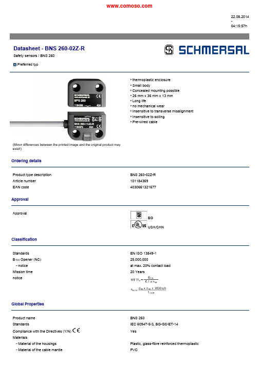
22.08.2014-04:15:57hDatasheet -BNS 260-02Z-RSafety sensors /BNS 260Preferredtyp(Minor differences between the printed image and the original product may exist!)•thermoplastic enclosure •Small body•Concealed mounting possible •26mm x 36mm x 13mm •Long life•no mechanical wear•Insensitive to transverse misalignment •Insensitive to soiling •Pre-wired cableOrdering detailsProduct type description BNS 260-02Z-R Article number 101184369EAN code4030661321677ApprovalApprovalBG USA/CANClassificationStandards EN ISO 13849-1B 10d Opener (NC)25.000.000-notice at max.20%contact load Mission time 20YearsnoticeGlobal PropertiesProduct name BNS 260StandardsIEC 60947-5-3,BG-GS-ET-14Compliance with the Directives(Y/N)YesMaterials-Material of the housings Plastic,glass-fibre reinforced thermoplastic -Material of the cable mantlePVCWeight52gCoding available(Y/N)YesMonitoring function of downstream devices(Y/N)NoPrerequisite evaluation unitRecommended safety-monitoring moduleRecommended actuator BPS260Mechanical dataDesign of electrical connection CableCable length1mConductors4x0,25mm²AWG-Numbermechanical installation conditions quasi-flushActive areaEnsured switch distance ON S ao5mmEnsured switch distance OFF S ar15mmnotice Axial misalignmentThe safety sensor and the actuator tolerate a horizontal and verticalmisalignment to each other.The possible misalignment depends on thedistance of the active surfaces of the sensor and the actuator.The sensoris active in the tolerance range.Type of actuation MagnetDirection of motion head-on with regard to the active surfacerestistance to shock30g/11msResistance to vibration10…55Hz,Amplitude1mmDoor hinge rightAmbient conditionsAmbient temperature-Min.environmental temperature−25°C-Max.environmental temperature+70°CStorage and transport temperature-Min.Storage and transport temperature−25°C-Max.Storage and transport temperature+70°CProtection class IP67Electrical dataIntegrated Safety monitoring module available(Y/N)NoCross circuit/short circuit recognition possible(Y/N)YesVoltage type VDCSwitch frequency max.5HzSwitching voltage max.75VDCSwitching current max.400mASwitching capacity max.10VAOutputsDesign of control outputNumber of shutters0pieceNumber of openers2pieceDesign of output signal switching deviceElectrical data-Safety outputsNumber of secure semi-conductor outputs0pieceNumber of secure outputs with contact2piece Electrical data-Diagnostic outputNumber of semi-conductor outputs with signaling function0pieceNumber of outputs with signaling function that already have a contact0pieceLED switching conditions displayLED switching conditions display(Y/N)NoATEXExplosion protection categories for gases NoneExplosion protected category for dusts None DimensionsDimensions of the sensor-Width of sensor26mm-Height of sensor36mm-Length of sensor13mmnoticeContact symbols shown for the closed condition of the guard device.The contact configuration for versions with or without LED is identical.Contact S21-S22und S11-S12must be integrated in the safety circuitIncluded in deliveryActuators must be ordered separately.Indication legendSwitch on/off diagramThe actuating graph also applies to the BPS260-2,the actuator with90°inverted actuation. DiagramNote Diagrampositive break NC contactactiveno activeNormally-open contactNormally-closed contactOrdering codeBNS260-(1)(2)Z(3)-(4)-(5)(1)111Normally open contact(NO)/1Opener(NC) 022Opener(NC)(2)without without Diagnostic output/011Opener(NC)(3)without without LED switching conditions displayG with LED switching conditions display(4)without Pre-wired cableST with connector(5)L Door hinge on left-hand sideR Door hinge on right-hand sideDocumentsOperating instructions and Declaration of conformity(pt)313kB,29.11.2011Code:mrl_bns260_ptOperating instructions and Declaration of conformity(cs)323kB,04.06.2012Code:mrl_bns260_csOperating instructions and Declaration of conformity(fr)269kB,19.04.2013Code:mrl_bns260_frOperating instructions and Declaration of conformity(de)266kB,17.01.2013Code:mrl_bns260_deOperating instructions and Declaration of conformity(it)264kB,18.03.2013Code:mrl_bns260_itOperating instructions and Declaration of conformity(br)699kB,11.08.2011Code:mrl_bns260_brOperating instructions and Declaration of conformity(nl)269kB,05.04.2013Code:mrl_bns260_nlOperating instructions and Declaration of conformity(pl)323kB,02.04.2012Code:mrl_bns260_plOperating instructions and Declaration of conformity(jp)389kB,24.06.2014Code:mrl_bns260_jpOperating instructions and Declaration of conformity(en)269kB,17.01.2013Code:mrl_bns260_enOperating instructions and Declaration of conformity(es)320kB,13.09.2011 Code:mrl_bns260_esOperating instructions and Declaration of conformity(da)314kB,27.08.2012 Code:mrl_bns260_daImagesDimensional drawing(basic component)Characteristic curveCharacteristic curveClipartSystem componentsActuator101184395-BPS260-1•Actuator and sensor on a mounting level101184396-BPS260-2•Actuator90°attached to the sensorAccessories101184643-SPACER BNS260to mount the magnetic safety sensor and actuator on ferromagneticmaterialK.A.Schmersal GmbH&Co.KG,Möddinghofe30,D-42279WuppertalThe data and values have been checked throroughly.Technical modifications and errors excepted.Generiert am22.08.2014-04:15:58h Kasbase2.2.18.F DBIImage: nImage: cet=sS9T&et。
Liebherr 冰箱产品说明书

4
存放........................................................................ 16
4.1 存放提示......................................................................... 16
3.15 连接设备......................................................................... 15
3.16 开启冰箱(首次调试)................................................. 15
5.2.1
用按键导航.................................................................. 17
5.2.2
设置菜单...................................................................... 17
5.3.11 Alarm Sound.............................................................. 22
5.3.12 Key Sound.................................................................. 22
3.1 安装条件......................................................................... 5
3.2 冰箱尺寸......................................................................... 6
斯耐克森 数字社区可视对讲门口主机 SNX-IPX-D11系列 IPX单摄像头门口主机 使用说明书
数字社区可视对讲门口主机使用说明书V1.3型号:SNX-IPX-D11系列SNX-IPX-D12系列SNX-IPX-D17系列SNX-IPX-D18系列SNX-IPX-D19系列SNX-IPX-D28系列SNX-IPX-D29系列SNX-IPX-D33系列目录产品简介: (2)基本功能介绍: (2)基本功能操作说明: (4)工程设置操作说明: (5)安装注意事项: (7)技术参数: (8)故障排查: (8)安全注意事项: (8)谢谢您使用斯耐克森数字智慧社区楼宇对讲系统的产品,使用前请详细阅读本手册。
请妥善保管本手册,以备日后参考。
由于技术的不断更新,手册中可能会于实际操作有不符之处,其最终解释权归本公司所有。
产品简介:可视对讲门口主机产品采用嵌入式安装设计,可以安装在单元入口作为单元门口主机,也可以安装在小区入口作为围墙门主机使用。
通过使用键盘拨号可以呼叫小区住户可视对讲分机,或者呼叫小区保安分机及管理中心电脑平台。
在核实来访者身份后,业主或者小区管理人员可以远程控制打开连接在门口机上的电控锁或者磁力锁。
除此之外,门口主机还有多种开锁方式,比如:密码开锁,刷卡开锁等等。
这些开门方式的操作说明都显示在门口主机的显示屏上供用户参考。
基本功能介绍:1.访客可视对讲:1.1门口主机可输入业主房号呼叫业主的室内机,进行可视对讲。
2.求助功能:2.1门口机可呼叫保安亭或者物业中心进行求助和咨询。
3.门禁开锁功能:3.1门口机可密码开锁。
3.2IC卡刷卡开锁。
3.3访客呼叫业主室内机,室内可远程开锁,打开本地门禁电控锁。
3.4求助保安亭或者物业中心开锁。
4.视频监控功能:4.1业主可通过室内机来监控单元门的图像,并可拍照保存。
4.2保安亭和物业中心可通过远程监控,来查看当前门口机的监控情况。
5.呼叫电梯功能:5.1门口机开锁的同时,呼叫电梯到1层。
5.2住户用刷卡开锁,密码开锁等开锁方式开锁后,打开住户对应楼层的电梯权限。
iTEMP TMT72温度传感器操作手册说明书
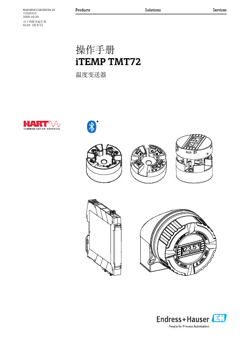
Products Solutions Services操作手册iTEMP TMT72温度变送器BA01854T/28/ZH/04.20715255132020-10-20自下列版本起生效01.01(版本号)iTEMP TMT72目录Endress+Hauser 3目录1文档信息 (4)1.1文档功能 (4)1.2安全指南(XA) (4)1.3信息图标 (4)1.4工具图标 (5)1.5文档资料代号 (6)1.6注册商标 (6)2基本安全指南 (7)2.1人员要求 (7)2.2预定用途 (7)2.3操作安全 (7)3到货验收和产品标识 (8)3.1到货验收 (8)3.2产品标识 (8)3.3供货清单 (9)3.4证书和认证 (10)3.5运输和储存 (10)4安装 (11)4.1安装条件 (11)4.2安装 (11)4.3安装后检查 (16)5电气连接 (17)5.1接线 (17)5.2快速接线指南 (18)5.3连接传感器电缆 (18)5.4连接变送器 (19)5.5特殊接线指南 (20)5.6连接后检查 (21)6操作方式 (22)6.1操作方式概览 (22)6.2操作菜单的结构和功能 (25)6.3通过调试软件访问操作菜单 (27)6.4通过SmartBlue App 访问操作菜单 (29)7系统集成 (31)7.1设备描述文件概述 (31)7.2HART 通信的测量变量 (31)7.3支持的HART ®命令 (31)8调试 (34)8.1安装后检查 (34)8.2打开变送器 (34)8.3设置测量设备 (34)8.4写保护设置,防止未经授权的访问 (36)9诊断和故障排除...................379.1常规故障排除........................379.2现场显示单元上的诊断信息..............399.3通过通信接口查看诊断信息..............399.4诊断信息列表........................399.5事件日志............................409.6诊断事件概览........................409.7固件变更历史........................4110维护..............................4211维修..............................4211.1概述...............................4211.2备件...............................4211.3返厂...............................4211.4废弃...............................4212附件..............................4212.1设备专用附件........................4312.2通信专用附件........................4312.3服务专用附件........................4312.4系统组件............................4413技术参数..........................4513.1输入...............................4513.2输出...............................4613.3电源...............................4713.4性能参数............................4813.5环境条件............................5513.6机械结构............................5613.7证书和认证..........................5913.8补充文档资料........................6114操作菜单和菜单参数说明...........6214.1Diagnostics:诊断菜单.................6614.2Application:应用菜单.................7214.3System:系统菜单....................82索引.. (97)文档信息iTEMP TMT724Endress+Hauser1 文档信息1.1 文档功能文档中包含仪表生命周期各个阶段内所需的所有信息:从产品标识、到货验收和储存,至安装、电气连接、操作和调试,以及故障排除、维护和废弃。
深圳市富满电子集团股份有限公司 TC2120 双节锂电池保护 IC 说明书

TC2120(文件编号:S&CIC0927)双节锂电池保护IC概述TC2120系列IC,内置高精度电压检测电路和延时电路,是用于2节串联锂离子/锂聚合物可再充电电池的保护IC。
此系列IC适合于对2节串联可再充电锂离子/锂聚合物电池的过充电、过放电和过电流进行保护。
特点TC2120全系列IC具备如下特点:(1)高精度电压检测电路过充电检测电压V CUn(n=1,2) 4.10V~4.50V精度±25mV过充电释放电压V CRn(n=1,2) 3.90V~4.30V精度±50mV过放电检测电压V DLn(n=1,2) 2.00V~3.00V精度±80mV过放电释放电压V DRn(n=1,2) 2.30V~3.40V精度±100mV放电过流检测电压(可选择)充电过流检测电压(可选择)精度±30mV负载短路检测电压 1.0V(固定)精度±0.4V(2)各延迟时间由内部电路设置(不需外接电容)过充电检测延迟时间典型值1000ms过放电检测延迟时间典型值110ms放电过流检测延迟时间典型值10ms充电过流检测延迟时间典型值7ms负载短路检测延迟时间典型值250μs(3)低耗电流工作模式典型值5.0μA,最大值9.0μA(VDD=7.8V)休眠模式最大值0.1μA(VDD=4.0V)(4)连接充电器的端子采用高耐压设计(CS端子和OC端子,绝对最大额定值是33V)(5)允许向0V电池充电功能(6)宽工作温度范围:-40℃~+85℃(7)小型封装:SOT-23-6(8)TC2120系列是无卤素绿色环保产品产品应用2节串联锂离子可再充电电池组。
2节串联锂聚合物可再充电电池组。
产品目录参数型号过充电检测电压过充电释放电压过放电检测电压过放电释放电压放电过流检测电压充电过流检测电压向0V电池充电功能V CUn V CRn V DLn V DRn V DIP V CIP V0CHTC2120-BB 4.35±0.025V 4.15±0.05V 2.30±0.08V 3.00±0.1V200±30mV-210±30mV允许TC2120-CB(A档)4.28±0.025V 4.08±0.05V 2.90±0.08V 3.00±0.1V200±30mV-210±30mV允许TC2120(文件编号:S&CIC0927)双节锂电池保护ICTC2120(文件编号:S&CIC0927)双节锂电池保护IC 绝对最大额定值(VSS=0V,Ta=25°C,除非特别说明)电气特性(VSS=0V,Ta=25°C,除非特别说明)TC2120(文件编号:S&CIC0927)双节锂电池保护ICTC2120(文件编号:S&CIC0927)双节锂电池保护IC *3、C1和C2有稳定VDD电压的作用,请不要连接0.01μF以下的电容。
三相电源监控三极监测器 CM-MPN.x2说明书
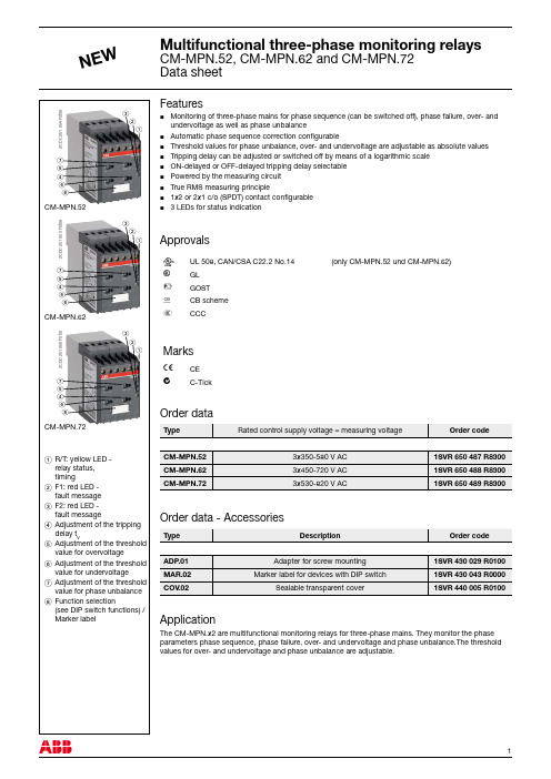
7 Adjustment of the threshold value for phase unbalance
8 Function selection (see DIP switch functions) / Marker label
Operating principle 2x1 c/o (SPDT) contact is mandatory if automatic phase sequence correction is activated.
DIP switch 4 = Automatic phase sequence correction
J Phase unbalance, phase sequence, phase failure, interrupted neutral: both output relays R1 (15-16/18) and R2 (25-26/28) react synchronously
Auto. phase sequence correction activated m:
In case of a fault, the output relays de-energize
instantaneously and a fault message is displayed
and stored for the length of the adjusted tripping
delay tV. Thereby, also momentary undervoltage conditions are recognized.
CM-MPN.52 CM-MPN.62 CM-MPN.72
Quectel_EC20_R2.0_硬件设计手册_V1.2
e 3.5.2. 飞行模式 ......................................................................................................................... 29 fid 3.6. 电源设计 ................................................................................................................................ 29
10. 图 31 增加备注 3。
11. 增加射频信号线 Layout 参考指导(5.1.4 章节)。
12. 更新模块耗流数据(表 33)。
13. 增加 GNSS 耗流数据(表 34)。
14. 更新 7.3 章节中模块俯视图。
上海移远通信技术股份ຫໍສະໝຸດ 限公司2 / 83EC20 R2.0 硬件设计手册
目录
3.6.1. 管脚介绍 ......................................................................................................................... 29 3.6.2. 减少电压跌落.................................................................................................................. 30
能源控制器Ⅰ型使用说明书

能源控制器Ⅰ型使用说明书青岛东软载波科技股份有限公司能源控制器类型标识代码分类说明NC X X X X-XXXX 能源控制器场景远程通信本地通信总线通信产品代号NC-能源控制器1-公变2-专变1-4G2-5G0-无1-HPLC2-微功率无线3-双模1-RS-4852-M-bus3-CAN由不大于8位的英文字母和数字组成。
英文字母可由生产企业名称拼音简称表示,数字代表产品设计序号能源控制器的功能模块类型标识代码分类见下表。
功能模块类型标识代码分类说明G X X X X-XXXX功能模块功能模块类型功能模块类型属性接口数量温度级别产品代号G-功能模块K-控制模块X-遥信模块B-本地通信模块Y-远程通信模块M-模拟量采集模块T-其他功能模块类型无补充属性,则为X;本地通信模块:Z-窄带电力线载波H-HPLCJ-微功率无线S-双模通信模块(载波&无线)M-MBUS通信模块R-RS485通信模块C-CAN通信模块T-其它信道远程通信模块:2-无线公网2G3-无线公网3G4-无线公网4G5-无线公网5GA-230MHz专网L-以太网有线网络N-公共交换电话网F-光纤有线网络T-其他信道多功能组合模块类型属性定义为:Z。
对外物理接口数量:1~9-1~9路物理接口1-C12-C23-C34-Cx由不大于8位的英文字母和数字组成,必须包含版本信息。
英文字母可由生产企业名称拼音简称表示,数字代表产品设计序号尊敬的用户:首先衷心感谢您选择青岛东软载波科技股份有限公司的产品。
青岛东软载波科技股份有限公司成立于1993年6月,2011年2月在创业板上市,现已形成以智能制造为基础,芯片设计为源头,能源互联网与智能化应用两翼齐飞的产业布局。
公司发展战略是以集成电路设计为基础,开展以融合通信为平台的技术研发;布局“芯片、软件(模组)、终端、系统、信息服务”产业链,聚焦能源互联网、智能化应用这两个战略新兴领域,打造国际一流企业。
GW2ANR系列FPGA产品数据手册DS961-1.3说明书
GW2ANR系列FPGA产品数据手册DS961-1.3, 2023-02-27版权所有© 2023广东高云半导体科技股份有限公司、Gowin、晨熙、高云均为广东高云半导体科技股份有限公司注册商标, 本手册中提到的其他任何商标,其所有权利属其拥有者所有。
未经本公司书面许可,任何单位和个人都不得擅自摘抄、复制、翻译本文档内容的部分或全部,并不得以任何形式传播。
免责声明本文档并未授予任何知识产权的许可,并未以明示或暗示,或以禁止发言或其它方式授予任何知识产权许可。
除高云半导体在其产品的销售条款和条件中声明的责任之外,高云半导体概不承担任何法律或非法律责任。
高云半导体对高云半导体产品的销售和/或使用不作任何明示或暗示的担保,包括对产品的特定用途适用性、适销性或对任何专利权、版权或其它知识产权的侵权责任等,均不作担保。
高云半导体对文档中包含的文字、图片及其它内容的准确性和完整性不承担任何法律或非法律责任,高云半导体保留修改文档中任何内容的权利,恕不另行通知。
高云半导体不承诺对这些文档进行适时的更新。
目录目录 (i)图目录 (iv)表目录 (vi)1 关于本手册 (1)1.1 手册内容 (1)1.2 相关文档 (1)1.3 术语、缩略语 (2)1.4 技术支持与反馈 (3)2 产品概述 (4)2.1 特性概述 (4)2.2 产品信息列表 (6)3 结构介绍 (7)3.1 结构框图 (7)3.2 Memory (8)3.2.1 SDR SDRAM (8)3.2.2 NOR FLASH (9)3.3 可配置功能单元 (10)3.4 输入输出模块 (11)3.4.1 简介 (11)3.4.2 I/O电平标准 (12)3.4.3 I/O逻辑 (14)3.4.4 I/O逻辑工作模式 (16)3.5 块状静态随机存储器模块 (22)3.5.1 简介 (22)3.5.2 存储器配置模式 (23)3.5.3 存储器混合数据宽度配置 (24)3.5.4 校验位功能配置 (25)3.5.5 同步操作 (25)3.5.7 BSRAM操作模式 (25)3.5.8 时钟模式 (27)3.6 数字信号处理模块 (28)3.6.1 简介 (28)3.6.2 数据A、数据B和进位C的加法/减法运算DSP操作模式配置 (31)3.7 时钟 (32)3.7.1 简介 (32)3.7.2 全局时钟网络 (32)3.7.3 锁相环 (35)3.7.4 高速时钟 (37)3.7.5 DDR存储器接口时钟管理DQS (37)3.8 长线 (38)3.9 全局复置位 (38)3.10 编程配置 (38)3.11 片内晶振 (39)4 电气特性 (40)4.1 工作条件 (40)4.1.1 绝对最大范围 (40)4.1.2 推荐工作范围 (41)4.1.3 电源上升斜率 (41)4.1.4 热插拔特性 (42)4.1.5 POR特性 (42)4.2 ESD性能 (42)4.3 DC电气特性 (42)4.3.1 推荐工作范围DC电气特性 (42)4.3.2 静态电流 (44)4.3.3 I/O推荐工作条件 (44)4.3.4 单端I/O DC电气特性 (45)4.3.5 差分I/O DC电气特性 (46)4.4 AC开关特性 (47)4.4.1 CFU开关特性 (47)4.4.2 BSRAM开关特性 (47)4.4.3 DSP开关特性 (47)4.4.4 Gearbox开关特性 (47)4.4.5 时钟和I/O开关特性 (47)4.4.7 锁相环开关特性 (48)4.5 编程接口时序标准 (48)5 器件订货信息 (49)5.1 器件命名 (49)5.2 器件封装标识示例 (50)图目录图3-1结构概念示意图 (7)图3-2 CFU结构示意图 (10)图3-3 IOB结构示意图 (11)图3-4 GW2ANR系列FPGA产品I/O Bank分布示意图 (12)图3-5 I/O逻辑输出示意图 (14)图3-6 I/O逻辑输入示意图 (14)图3-7 IODELAY示意图 (15)图3-8 GW2ANR的I/O寄存器示意图 (15)图3-9 GW2ANR的IEM示意图 (16)图3-10普通模式下的I/O逻辑结构示意图 (16)图3-11 SDR模式下的I/O逻辑结构示意图 (17)图3-12 I/O逻辑的DDR输入示意图 (17)图3-13 I/O逻辑的DDR输出示意图 (17)图3-14 I/O逻辑的IDES4输入示意图 (18)图3-15 I/O逻辑的OSER4输出示意图 (18)图3-16 I/O逻辑的IVideo输入示意图 (18)图3-17 I/O逻辑的OVideo输出示意图 (19)图3-18 I/O逻辑的IDES8输入示意图 (19)图3-19 I/O逻辑的OSER8输出示意图 (19)图3-20 I/O逻辑的IDES10输入示意图 (19)图3-21 I/O逻辑的OSER10输出示意图 (20)图3-22 IO逻辑的IDDR_MEM输入示意图 (20)图3-23 IO逻辑的ODDR_MEM输出示意图 (20)图3-24 IO逻辑的IDES4_MEM输入示意图 (21)图3-25 IO逻辑的OSER4_MEM输出示意图 (21)图3-26 IO逻辑的IDES8_MEM输入示意图 (21)图3-27 IO逻辑的OSER8_MEM输出示意图 (22)图3-28单端口、伪双端口及双端口模式下的流水线模式 (26)图3-29独立时钟模式 (27)图3-30读写时钟模式 (27)图3-31单端口时钟模式 (28)图3-32 DSP宏单元 (29)图3-33 GW2ANR时钟资源 (32)图3-34 GCLK象限分布示意图 (33)图3-35 DQCE结构示意图 (34)图3-36 DCS接口示意图 (34)图3-37 DCS Rising Edge模式下的时序示意图 (34)图3-38 DCS Falling Edge模式下的时序示意图 (35)图3-39 PLL示意图 (35)图3-40 GW2ANR HCLK示意图 (37)图3-41 DQS示意图 (38)图5-1器件命名方法–ES (49)图5-2器件命名方法–Production (49)图5-3器件封装标识示例 (50)表目录表1-1术语、缩略语 (2)表2-1产品信息列表 (6)表2-2 GW2ANR-18列表 (6)表3-1 GW2ANR系列FPGA产品支持的输出I/O类型及部分可选配置 (13)表3-2 端口介绍 (14)表3-3 BSRAM信号功能 (23)表3-4存储器配置列表 (23)表3-5双端口混合读写数据宽度配置列表 (24)表3-6伪双端口混合读写数据宽度配置列表 (25)表3-7时钟模式配置列表 (27)表3-8 DSP端口描述 (29)表3-9内部寄存器描述 (30)表3-10 PLL端口定义 (36)表3-11片内晶振的输出频率选项 (39)表4-1绝对最大范围 (40)表4-2推荐工作范围 (41)表4-3电源上升斜率 (41)表4-4热插拔特性 (42)表4-5 POR电压标准 (42)表4-6 GW2ANR ESD - HBM (42)表4-7 GW2ANR ESD - CDM (42)表4-8推荐工作范围内DC电气特性 (42)表4-9静态电流 (44)表4-10 I/O推荐工作条件 (44)表4-11单端I/O DC电气特性 (45)表4-12差分I/O DC电气特性 (46)表4-13 CFU时序参数 (47)表4-14 BSRAM时序参数 (47)表4-15 DSP时序参数 (47)表4-16 Gearbox时序参数 (47)表4-17外部开关特性 (47)表4-18片内晶振特性参数 (48)表4-19 PLL特性参数 (48)1关于本手册 1.1手册内容1关于本手册1.1手册内容GW2ANR系列FPGA产品数据手册主要包括高云半导体GW2ANR系列FPGA产品特性概述、产品资源信息、内部结构介绍、电气特性、编程接口时序以及器件订货信息,帮助用户快速了解高云半导体GW2ANR系列FPGA产品以及特性,有助于器件选型及使用。
展讯平台NPI工具介绍

2011-5-16
保密信息
. 10
展讯平台NPI工具介绍 工具介绍 展讯平台
WriteIMEI工具操作和设置界面 工具操作和设置界面
2011-5-16
保密信息
. 11
展讯平台NPI工具介绍 工具介绍 展讯平台
MobileTVtester: :
主要用于CMMB电视测试。支持 电视测试。支持USB/UART双模式操作。现阶段仅支持手机 双模式操作。 主要用于 电视测试 双模式操作 Cal Mode测试。 测试。 测试 ※测试内容: 测试内容: 信号接收灵敏度测试。 *RSSI test : CMMB信号接收灵敏度测试。 信号接收灵敏度测试 信号接受误块率测试 *BLER test:CMMB信号接受误块率测试。 : 信号接受误块率测试。
2011-5-16
保密信息
.8
展讯平台NPI工具介绍 工具介绍 展讯平台
WriteSN程序界面和主要设置框 程序界面和主要设置框
信息显示区域
SN输入区域 输入区域
设置窗口
2011-5-16
保密信息
.9
展讯平台NPI工具介绍 工具介绍 展讯平台
WriteIMEI
主要用于产线IMEI号码和蓝牙地址的写入。支持USB/UART双模式操作。 号码和蓝牙地址的写入。支持 双模式操作。 主要用于产线 号码和蓝牙地址的写入 双模式操作 支持串号自动生成。 支持串号自动生成。 ※主要功能: 主要功能: 串号的自动生成和写入, * IMEI串号的自动生成和写入,支持手动输入。 串号的自动生成和写入 支持手动输入。 的自动生成和写入, * BT Mac address的自动生成和写入,支持手动输入。 的自动生成和写入 支持手动输入。 对已经写入机内的IMEI串号读取。 串号读取。 * 对已经写入机内的 串号读取
数据采集软硬件解决方案
DAQ 事业部将精心为您提供:
● 专业的售前咨询服务: DAQ 事业部工程师将根据您的测试要求以及预算为您度身 定制软硬件测试解决方案。 ● 完善的售后支持服务: DAQ 事业部将为您提供专家级的售后技术支持以及产品售 后质量保证服务。 ● NI 数据采集卡批量折扣支持 为 OEM 用户提供购买 NI 数据采集卡批量折扣优惠。 ● NI 数据采集卡租借服务 为 OEM 用户提供 NI 数据采集卡租借服务,降低 OEM 用户 前期研发成本。 ● 产品增值服务 为OEM用户提供产品增值服务,协助OEM更快推出新产品。 ● 培训课程服务 DAQ 事业部为使用 Visual Basic,Visual C++,Visual 的工程师提供 NI Measurement Studio 软件收 费培训课程服务,并为学员授予 DAQ 事业部与 NI 联合认 证的专业培训证书。
2006 年 5 月 8 日 DAQ 事业部推出全新 EaziDAQ 数据记 录软件,该软件是专为使用 NI 数据采集卡的用户提供的功 能强大、方便易用的数据记录软件。使用 EaziDAQ 数据记 录软件不仅可以获得实时的波形显示,更可以方便地进行数 据记录以及历史数据的动态回放等操作。
EaziDAQ 数据记录软件能够为您提供:
测量与自动化软件 DAQ 事业部软件产品(EaziDAQ 数据记录软件)............ 33
PCI 总线 PCI 总线(M 系列多功能数据采集产品)........................ 10 PCI 总线(S 系列同步多功能数据采集产品).................. 18 PCI 总线(数字 I/O 产品)................................................ 19 PCI 总线(计时器 / 定时器产品)..................................... 24 PCI 总线(模拟输出产品)............................................... 26
SIMATIC IPC547J SIMATIC 工业 PC SIMATIC IPC547J 操作说明
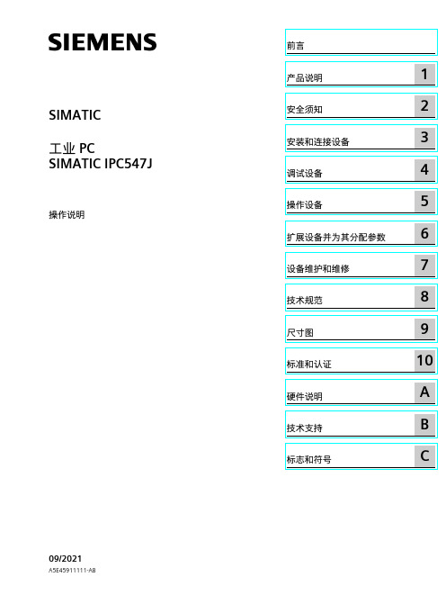
C
法律资讯
警告提示系统
为了您的人身安全以及避免财产损失,必须注意本手册中的提示。人身安全的提示用一个警告三角表示,仅 与财产损失有关的提示不带警告三角。警告提示根据危险等级由高到低如下表示。
危险 表示如果不采取相应的小心措施,将会导致死亡或者严重的人身伤害。
警告 表示如果不采取相应的小心措施,可能导致死亡或者严重的人身伤害。
Siemens AG Digital Industries Postfach 48 48 90026 NÜRNBERG 德国
A5E45911111-AB Ⓟ 09/2021 本公司保留更改的权利
Copyright © Siemens AG 2021. 保留所有权利
前言
本操作说明的用途 本操作说明包含 SIMATIC IPC547J 安装、电气连接、调试和扩展以及维护和维修设备所需 的全部信息。本操作说明是专为以下具有资质的专业人员编写的: • 装配工 • 调试工程师 • IT 管理员 • 维修与维护人员
SIMATIC IPC547J
SIMATIC 工业 PC SIMATIC IPC547J
操作说明
09/2021
A5E45911111-AB
前言
产品说明
1
安全须知
2
安装和连接设备
3
调试设备
4
操作设备
5
扩展设备并为其分配参数
6
设备维护和维修
7
技术规范
8
尺寸图
9
标准和认证
10
硬件说明
A
技术支持
B
标志和符号
小心 表示如果不采取相应的小心措施,可能导致轻微的人身伤害。
பைடு நூலகம்注意
- 1、下载文档前请自行甄别文档内容的完整性,平台不提供额外的编辑、内容补充、找答案等附加服务。
- 2、"仅部分预览"的文档,不可在线预览部分如存在完整性等问题,可反馈申请退款(可完整预览的文档不适用该条件!)。
- 3、如文档侵犯您的权益,请联系客服反馈,我们会尽快为您处理(人工客服工作时间:9:00-18:30)。
Date: Version Total Page
2015-07-09 SF 7
DC/DC
Specification
公 司 名 称 CUSTOMER 产 品 名 称 TYPE 型 号 PART NO.
DC/DC
LC2137
贵公司部品号 CUSTOMER’S PART NO.
0.5
Note: *When Dutycycle >80%, Inoload will increase. e.g. Vin=3.6V/Vout=3.3V, Inoload=1mA.
2
Your final power solution
LC2137
PIN DESCRIPTION
Value
8V 125C -40C – 85C 400mW -40C - 150C 260C, 10S >2000V
Note: Exceed these limits to damage to the device. Exposure to absolute maximum rating conditions may affect device reliability.
TYPICAL APPLICATION
PIN OUT & MARKING
GP: Product Code YW: Date code (Year & Week)
1
Your final power solution
LC2137
ORDERING INFORMATION
PART No.
Efficiency vs. Output Current
(Vout=1.8V)
Vin=3.6V Vin=4.0V Vin=5.0V Vin=6.0V 0.1 Iout (A) 1 10
Efficiency vs. Output Current
(Vout=3.3V)
100% 90% 80% Efficiency 70% 60% 50% 40% 30% 20% 10% 0% 0.01 0.1 Iout (A) 1 Vin=3.6V Vin=4.0V Vin=5.0V Vin=6.0V 10
LC2137
1.2A 1.5MHz 7V Synchronous Buck Converter
DESCRIPTION
The LC2137 is a high-efficiency, DC-to-DC stepdown switching regulators, capable of delivering up to 1.2A of output current. The device operates from an input voltage range of 2.6V to 7V and provides an output voltage from 0.6V to VIN, making the LC2137 ideal for low voltage power conversions. Running at a fixed frequency of 1.5MHz allows the use of small external components, such as ceramic input and output caps, as well as small inductors, while still providing low output ripples. This low noise output along with its excellent efficiency achieved by the internal synchronous rectifier, making LC2137 an ideal green replacement for large power consuming linear regulators. Internal softstart control circuitry reduces inrush current. Shortcircuit and thermal-overload protection improves design reliability. LC2137 is housed in a SOT23-5 Package.
PIN #
1 2 3 4 5
NAME
EN GND SW VIN FB
DESCRIPTION
Enable pin for the IC. Drive the pin to high to enable the part, and low to disable Ground Inductor connection. Connect an inductor between SW and the regulator output. Supply voltage. Feedback input. Connect an external resistor divider from the output to FB and GND to set the output to a voltage between 0.6V and Vin
0.1 0.1 1.5 250 150 1.2 1.5 75
0.2 0.2 350 250 2 1 1
Vin=5V, Vout=3.3V, Iout=0 SW Leakage Current EN Leakage Current EN Input High Voltage EN Input Low Voltage 1 Vout=6V, VSW=0 or 6V, EN=0V
Symbol
Vin Vref Ifb Iq LnReg LdReg Fsoc RdsonP RdsonN Ilimit Inoload* Iswlk Ienlk Vh_en Vl_en
Parameter
Input Voltage Range Feedback Voltage Feedback Leakage current Quiescent Current Line Regulation Load Regulation Switching Frequency PMOS Rdson NMOS Rdson Peak Current Limit Vin=5V
RECOMMENDED WORK CONDITIONS
Parameter
Input Voltage Range Operating Junction Temperature(Tj)
Value
7V -20C –125C
ELECTRICAL CHARACTERISTICS
(Vin=5V, TA=25C)
APPLICATIONS
Cellular phones Digital Cameras MP3 and MP4 players Set top boxes Wireless and DSL Modems USB supplied Devices in Notebooks Portable Devices
BLOCK DIAGRAM
DETAILED DESCRIPTION
The LC2137 high-efficiency switching regulator is a small, simple, DC-to-DC step-down converter capable of delivering up to 1A of output current. The device operates in pulse-width modulation (PWM) at 1.5MHz from a 2.6V to 7V input voltage and provides an output voltage from 0.6V to VIN, making the LC2137 ideal for on-board postregulation applications. An internal synchronous rectifier improves efficiency and eliminates the typical Schottky free-wheeling diode. Using the on resistance of the internal high-side MOSFET to sense switching currents eliminates current-sense resistors, further improving efficiency and cost. on until the PWM comparator terminates the on cycle. During this on-time, current ramps up through the inductor, sourcing current to the output and storing energy in the inductor. The current mode feedback system regulates the peak inductor current as a function of the output voltage error signal. During the off cycle, the internal highside P-channel MOSFET turns off, and the internal low-side N-channel MOSFET turns on. The inductor releases the stored energy as its current ramps down while still providing current to the output.
