CTDO3340PF-683中文资料
富满电子集团TC6833E非隔离降压型LED恒流控制器说明书

TC6833E(文件编号:S&CIC1439)非隔离降压型LED恒流控制器概述TC6833E是一款高精度降压型LED恒流驱动芯片。
芯片工作在电感电流临界连续模式。
TC6833E芯片内部集成500V功率开关,采用专利的驱动和电流检测方式,芯片的工作电流极低,无需辅助绕组检测和供电,只需要很少的外围元件,即可实现优异的恒流特性,极大的节约了系统成本和体积。
TC6833ES芯片内带有高精度的电流采样电路,同时采用了专利的恒流控制技术,实现高精度的LED恒流输出和优异的线电压调整率。
芯片工作在电感电流临界模式,输出电流不随电感量和LED工作电压的变化而变化,实现优异的负载调整率。
TC6833ES具有多重保护功能,包括LED开路/短路保护,欠压保护,芯片温度过热调节等。
两种封装形式:SOP-8(TC6833ES)、DIP-8(TC6833ED)。
特点电感电流临界连续模式内部集成500V功率管无需辅助绕组检测和供电芯片超低工作电流宽输入电压±5%LED输出电流精度LED开路保护LED短路保护芯片供电欠压保护过热调节功能应用LED蜡烛灯LED球泡灯其它LED照明引脚示意图及说明TC6833E(文件编号:典型应用2D1-D4TC6833E(文件编号:S&CIC1439)非隔离降压型LED恒流控制器极限参数并不完全保证满足个别性能指标。
电气参数定义了器件在工作范围内并且在保证特定性能指标的测试条件下的直流和交流电参数规范。
对于未给定上下限值的参数,该规范不予保证其精度,但其典型值合理反映了器件性能。
注2:温度升高最大功耗一定会减小,这也是由T JMAX,θJA,和环境温度T A所决定的。
最大允许功耗为P DMAX=(T JMAX-T A)/θJA或是极限范围给出的数字中比较低的那个值。
注3:人体模型,100pF电容通过1.5KΩ电阻放电。
推荐工作范围TC6833E(文件编号:S&CIC1439)非隔离降压型LED恒流控制器电气参数(无特别说明情况下,V CC=15V,T A=25℃)注5:规格书的最小、最大规范范围由测试保证,典型值由设计、测试或统计分析保证。
34063使用方法

34063 34063A的使用34063的应用34063由于价格便宜,开关峰值电流达1.5A,电路简单且效率满足一般要求,所以得到广泛使用。
在ADSL应用中,34063的开关频率对传输速率有很大影响,在器件选择及PCB设计时需要仔细考虑。
线性稳压电源效率低,所以通常不适合于大电流或输入、输出电压相差大的情况。
开关电源的效率相对较高,而且效率不随输入电压的升高而降低,电源通常不需要大散热器,体积较小,因此在很多应用场合成为必然之选。
开关电源按转换方式可分为斩波型、变换器型和电荷泵式,按开关方式可分为软开关和硬开关。
斩波型开关电源斩波型开关电源按其拓扑结构通常可以分为3种:降压型(Buck)、升压型(Boost)、升降压型(Buck-boost)。
降压型开关电源电路通常如图1所示。
图1中,T为开关管,L1为储能电感,C1为滤波电容,D1为续流二极管。
当开关管导通时,电感被充磁,电感中的电流线性增加,电能转换为磁能存储在电感中。
设电感的初始电流为iL0,则流过电感的电流与时间t的关系为:iLt= iL1+(Vi-Vo-Vs)t/L,Vs为T的导通电压。
当T关断时,L1通过D1续流,从而电感的电流线性减小,设电感的初始电流为iL1,则则流过电感的电流与时间t的关系:iLt="iL1-"(Vo+Vf)t/L,Vf为D1的正向饱和电压。
图1降压型开关电源基本电路34063的特殊应用● 扩展输出电流的应用DC/DC转换器34063开关管允许的峰值电流为1.5A,超过这个值可能会造成34063永久损坏。
由于通过开关管的电流为梯形波,所以输出的平均电流和峰值电流间存在一个差值。
如果使用较大的电感,这个差值就会比较小,这样输出的平均电流就可以做得比较大。
例如,输入电压为9V,输出电压为3.3V,采用220μH 的电感,输出平均电流达到900mA,峰值电流为1200mA。
单纯依赖34063内部的开关管实现比900mA更高的输出电流不是不可以做到,但可靠性会受影响。
MC34063芯片原理与应用技巧(车充)

MC34063芯片原理与应用技巧(车充)1. MC34063 DC/DC变换器控制电路简介:MC34063是一单片双极型线性集成电路,专用于直流-直流变换器。
它能使用很少的外接元件构成开关式升压变换器、降压变换器和电源反向器。
特点:价格便宜0.2元,电路简单,且效率满足一般要求*能在3-40V的输入电压下工作; *低静态电流;*电流限制;*输出电压可调*输出开关电流峰值可达1.5A(平均0.8A)(无外接三极管时)*工作振荡频率从100HZ到100KHZ2.MC34063引脚图及原理框图MC34063 电路原理振荡器通过恒流源对外接在CT 管脚(3 脚)上的定时电容不断地充电和放电以产生振荡。
充电和放电电流都是恒定的,振荡频率仅取决于③脚外接的定时电容。
与门的C 输入端在定时电容充电时为高电平,D 输入端在比较器的输入电平低于阈值电平时为高电平。
当C 和D输入端都变成高电平时触发器被置为高电平,输出开关管导通;反之当振荡器定时电容(③脚上)在放电期间,C 输入端为低电平,触发器被复位,使得输出开关管处于关闭状态。
电流限制通过检测连接在VCC(即6脚)和7 脚之间安全电阻(Rsc)上的压降来实现,当检测到电阻上的电压降接近超过0.3V 时,电流限制电路开始工作,这时通过CT 管脚(3 脚) 对定时电容进行快速充电以减少充电时间和输出开关管的导通时间,结果是使得输出开关管的关闭时间延长。
如⑧②两脚直接连到电源的正负极上,那么, T2上将承受很高的压降:为防T2因承压→发热过大,应在⑧或②外接电阻|电感等负载★。
线性稳压电源效率低,通常不适合于大电流或输入、输出压差大的情况。
开关电源的效率相对较高,按转换方式可分为斩波型、变换器型和电荷泵式,按开关方式可分为软开关和硬开关。
MC34063属于低成本斩波型硬开关。
有一个车用手机充电器(车充),芯片是MC34063,MicroUSB接口。
MC340631. MC34063实现的低端车充方案优点::低成本,接驳灵活缺点:(1) 可靠性差,功能单一;没有过温度保护,短路保护等安全性措施;(2) 输出虽然是直流电压,但控制输出恒流充电电流的方式为电流峰值限制,精度不够高;(3) 由于34063开关电流PWM+PFM模式(PWM是利用波脉冲宽度控制输出,PFM是利用脉冲的有无控制输出),其车充方案输出电压纹波较大,不够纯净;输出电流能力也非常有限;(常见于300ma~600ma之间的低端车充方案中)2. MC34063应用电路图:2.1 MC34063基本降压变换器电路(图中安全电阻Rsc=0.3Ω故电流峰值被限在0.3V/0.3Ω=1A,设50%占空比,则平均0.5A★)。
高频开关电源模块

高频开关电源模块技术手册石家庄福润新技术有限公司版权所有目录第一章概述 (3)一、简述 (3)二、模块主要特点 (3)三、型号命名 (4)四、技术指标 (4)第二章使用环境 (5)第三章模块构成 (5)一、模块的工作原理 (5)二、模块外观及外形尺寸 (6)三、模块安装 (7)四、操作说明 (11)第一章概述一、简述●我公司自主研发的FRDZ系列智能型高频开关电源,是专为电力系统设计,具有“四遥”功能的高频开关电源,模块采用世界领先的“谐振电压型双环控制的谐振开关电源技术”,具有体积小、重量轻、效率高、可靠性高等优点。
产品包括220V多个型号,配有标准RS-485接口,易于与自动化系统对接,适用于各类变电站、发电厂及水电站。
●我公司第三代(-3型)产品采用了LED数码管显示,进一步提高了产品的可靠性和美观性。
我公司-3型产品主要有以下型号:模块型号额定电压(V)额定电流(A)冷却方式外形尺寸(深×高×宽mm)FRDZ220D05Z-3 220 5 自然冷却260×179×109FRDZ220D07Z-3 220 7 自然冷却325×230×130FRDZ220D10Z-3 220 10 自然冷却325×230×130FRDZ220D20Z-3 220 20 自然冷却400×323×146二、模块主要特点●效率高,模块效率可达到95%~96%。
●重量轻,体积小。
●采用“三相无源功率因数校正电路”,输入无中线,功率因数可达0.94。
●采用隔离自主均流,并机不均流度<±3%,可保证二十台以上模块良好并机。
●模块内置直流输出隔离二极管,用户无需外设。
●模块具有RS-485接口,方便接入自动化系统进行通信。
●模块为LED数码管显示,分别设置显示切换按钮、手动调压按钮、拨码开关,操作简单。
●输出过压保护:内置过压保护电路,出现过压后模块自动锁死,模块故障指示灯亮,故障模块自动退出工作,不影响整个系统正常运行;过压保护点:220V模块为320V±5%,110V模块为160V±5%。
3300系列耐用封闭型磁电流表关闭阀门闸控制、警报和限位用途说明书
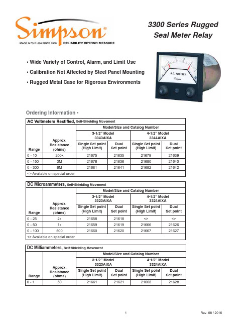
3300 Series RuggedSeal Meter Relay• Wide Variety of Control, Alarm, and Limit Use• Calibration Not Affected by Steel Panel Mounting• Rugged Metal Case for Rigorous EnvironmentsOrdering Information-DC Microammeters, Self-Shielding MovementRangeApprox.Resistance(ohms)Model/Size and Catalog Number3-1/2” Model3323AIXA4-1/2” Model3324AIXASingle Set point(High Limit)DualSet pointSingle Set point(High Limit)DualSet point0 - 252k2165821618<><> 0 - 501k21659216192166621626 0 - 10050021660216202166721627<> Available on special orderDC Milliammeters, Self-Shielding MovementRangeApprox.Resistance(ohms)Model/Size and Catalog Number3-1/2” Model3323AIXA4-1/2” Model3324AIXASingle Set point(High Limit)DualSet pointSingle Set point(High Limit)DualSet point0 - 150216612162121668216283300 Series RuggedSeal Meter Relay Ordering Information -DC Millivoltmeters, Self-Shielding MovementRangeApprox.Resistance(ohms)Model/Size and Catalog Number3-1/2” Model3323AIXA4-1/2” Model3324AIXASingle Set point(High Limit)DualSet pointSingle Set point(High Limit)DualSet point0 - 501k21663216232167021630 DC Voltmeters, Self-Shielding MovementRangeApprox.Resistance(ohms)Model/Size and Catalog Number3-1/2” Model3323AIXA4-1/2” Model3324AIXASingle Set point(High Limit)DualSet pointSingle Set point(High Limit)DualSet point0 - 120k21664216242167121631 0 - 501M21665216252167221632DC Ammeters, Self-Shielding MovementRangeApprox.Impedance(ohms)Model/Size and Catalog Number3-1/2” Model3323AIXA4-1/2” Model3324AIXASingle Set point(High Limit)DualSet pointSingle Set point(High Limit)DualSet point0 - 5.0121662216222166921629 Percent Motor Load, Self-Shielding MovementScale Range F.S.Catalog NumberSingle Set point(High Limit)Catalog NumberDouble Set point Model0-150 *10 VAC21684 * 21644 *3344 AIXA 4-1/2”0-150 ** 5 amp AC21683 **21643 **3344 AIXA 4-1/2”0-150 ** 5 amp AC35096 **35097 **3343 AIXA 3-1/2”* Use with Model 186 current transformers** Use with current transformers3300 Series Rugged Seal Meter Relay3300 Series RuggedSeal Meter RelayTemperature MetersOrdering Information -Temperature Range ThermocoupleTypeCatalog NumberModel# 3324 AIXA 4-1/2”SSP DSP0 to 300°F (0°C to +149°C)Type J 21651216110 to 500°F (0°C to +260°C)2165221612 0 to 750°F (0°C to +399°C)2165321613 0 to 1000°F (0°C to +538°C2165421614 0 to 1500°F (0°C to +815°C)Type K2165521615 0 to 2500°F (0°C to +1371°C)2165721617 Thermocouples are not supplied. Available separately from Accessory Section3300 Series RuggedSeal Meter Relay Dimensions4 - 1/2” - Model 3344AIXA & 3324AIXA3 - 1/2”- Model 3343AIXA & 3323AIXASimpson Electric Co.520 Simpson Ave.Lac du Flambeau, Wi 54538Ph: (715) 588-3311。
EATON 电路保护器型号C的更新内容说明书

EATON Content Details:This document describes brief details about EATON content update released for customer use. Each category describes type & series that got updated with the patch.CB (Circuit Breakers):Following series contents are added/updated.MOLDED CASE CIRCUIT BREAKERS - UPDATED•Type EHD Series C (F-FRAME MOLDED CASE CIRCUIT BREAKERS)•Type FD Series C (F-FRAME MOLDED CASE CIRCUIT BREAKERS)•Type FDB Series C (F-FRAME MOLDED CASE CIRCUIT BREAKERS)•Type FDC Series C (F-FRAME MOLDED CASE CIRCUIT BREAKERS)•Type HFD Series C (F-FRAME MOLDED CASE CIRCUIT BREAKERS)MOLDED CASE CIRCUIT BREAKERS - ADDED•Type ED Series C (F-FRAME MOLDED CASE CIRCUIT BREAKERS)•Type EDS Series C (F-FRAME MOLDED CASE CIRCUIT BREAKERS)•Type EDB Series C (F-FRAME MOLDED CASE CIRCUIT BREAKERS)•Type EDC Series C (F-FRAME MOLDED CASE CIRCUIT BREAKERS)•Type EDH Series C (F-FRAME MOLDED CASE CIRCUIT BREAKERS)•Type HJD Series C (J-FRAME MOLDED CASE CIRCUIT BREAKERS)•Type JD Series C (J-FRAME MOLDED CASE CIRCUIT BREAKERS)•Type JDB Series C (J-FRAME MOLDED CASE CIRCUIT BREAKERS)•Type JDC Series C (J-FRAME MOLDED CASE CIRCUIT BREAKERS)•Type HKD Series C (K-FRAME MOLDED CASE CIRCUIT BREAKERS)•Type KD Series C (K-FRAME MOLDED CASE CIRCUIT BREAKERS)•Type KDC Series C (K-FRAME MOLDED CASE CIRCUIT BREAKERS)•Rotary Handle Mechanisms, Shafts & Guide (FOR SERIES C MOLDED CASE CIRCUIT BREAKERS) These series also include accessories.CR (Control Relays)Following series contents are added.PLUG-IN CONTROL RELAYS - COMPACT•D1 Series (COMPACT 1P MULTI-FEATURE PLUG-IN CONTROL RELAYS)•D2 Series (COMPACT 2P & 4P MULTI-FEATURE PLUG-IN CONTROL RELAYS)•D3 Series (COMPACT 2P & 3P MULTI-FEATURE PLUG-IN CONTROL RELAYS)•D4 Series (COMPACT 1P & 2P SLIM-FIT MULTI-FEATURE PLUG-IN CONTROL RELAYS)•D5 Series (COMPACT 2P & 3P MULTI-FEATURE PLUG-IN CONTROL RELAYS)•D7 Series (COMPACT 1P, 2P, 3P & 4P MULTI-FEATURE PLUG-IN CONTROL RELAYS)These series also include base sockets for panel/din rail mounting.DR (Drives)Following series contents are added.OEM DRIVES•DE1 Series (PowerXL OEM VF DRIVES)•DXG Series (PowerXL AF DRIVES BEZEL KIT)•SVX9000 Series (SENSORLESS VECTOR AF DRIVES FLANGE KITS)GENERAL PURPOSE HVAC DRIVES•HMAX Series (Bezel)DS (Disconnect Switches)Following series contents are added.ROTARY DISCONNECTS, FUSIBLE AND NON-FUSIBLE•R4 Series (UL-98 COMPACT FUSIBLE 30A)•R5 Series (UL-508 NON-FUSIBLE 16-80A)•R9 Series (UL-98 NON-FUSIBLE 30-100A COMPACT)•R9 Series (UL-98 NON-FUSIBLE 100-1200A)•R9 Series (UL-98 FUSIBLE 30-800A)•R5 & R9 Series (HANDLES, SHAFTS, LUGS, TERMINAL SHROUDS)These series also include accessories.LT (Pilot Lights)Following series contents are added.•C22 Series (INDICATING LIGHTS, FLUSH)•M22 Series (INDICATING LIGHTS, FLUSH AND CONICAL LENS)MS (Motor Starters/Contactors)Following series contents are added/Updated.DEFINITE PURPOSE CONTACTORS•C25 Series (2P & 3P DP CONTACTORS 15-50A FRAME D)•C25 Series (2P & 3P DP CONTACTORS 25-40A FRAME E)DEFINITE PURPOSE STARTERS•A25 Series (THREE PHASE DP STARTERS 25-60A, COMMON & SEPARATE CONTROL) •B25 Series (SINGLE PHASE DP STARTERS 25-40A, COMMON & SEPARATE CONTROL) IEC POWER CONTROL•XTCE Series (FRAMES F&G CONTACTORS - UPDATED)•XTCE Series (FRAMES B THRU G CONTACTORS WITH CAGE TERMINALS)•XTSC Series (MANUAL MOTOR CONTROLLERS FVNR)•XTSR Series (MANUAL MOTOR CONTROLLERS FVR)•XTFC Series (COMBINATION MOTOR CONTROLLERS FVNR)•XTFR Series (COMBINATION MOTOR CONTROLLERS FVR)•XTAE Series (FRAME B STARTERS 7A-15.5A, XTOB BIMETALLIC OVERLOAD)•XTAE Series (FRAME C STARTERS 18A-32A, XTOB BIMETALLIC OVERLOAD)•XTAE Series (FRAME D STARTERS 40A-65A, XTOB BIMETALLIC OVERLOAD)•XTAE Series (FRAME F STARTERS 80A-95A, XTOB BIMETALLIC OVERLOAD)•XTAE Series (FRAME G STARTERS 115A-150A, XTOB BIMETALLIC OVERLOAD)•XTAE Series (FRAME B STARTERS 7A-15.5A, XTOE ELECTRONIC OVERLOAD)•XTAE Series (FRAME C STARTERS 18A-32A, XTOE ELECTRONIC OVERLOAD)•XTAE Series (FRAME D STARTERS 40A-65A, XTOE ELECTRONIC OVERLOAD)•XTAE Series (FRAME F STARTERS 80A-95A, XTOE ELECTRONIC OVERLOAD)•XTAE Series (FRAME G STARTERS 115A-150A, XTOE ELECTRONIC OVERLOAD)These series also include accessories.NEMA STARTERS•AN16 Series (NEMA STARTERS, SIZES 00-8)•AN56 Series (NEMA REVERSING STARTERS, SIZES 00-0)•AN19 Series (NEMA STARTERS, SIZES 00-2)SOFT STARTERS (REDUCED VOLTAGE MOTOR STARTERS)•S611 Series (ADVANCED FEATURE SET, USER-FRIENDLY UI SOFT STARTERS)•S801+ Series (COMPACT MULTI-FUNCTION SOFT STARTERS)•S811+ Series (COMPACT & COMMUNICATING MULTI-FUNCTION SOFT STARTERS)OL (Overload Relays)Following series contents are added.•C440 Series (SEPARATE MOUNT THERMAL OVERLOAD RELAYS)•XTOE Series (SEPARATE MOUNT ELECTRONIC OVERLOAD RELAYS)•C440 Series (COMMUNICATION ADAPTER)•C440 Series (REMOTE RESET MODULE)•ZEB Series (REMOTE RESET MODULES)PB (Pushbuttons)Following series contents are added.•C22 Series (NON-ILLUMINATED E-STOPS, TWIST RELEASE & KEY RELEASE)•C22 Series (NON-ILLUMINATED FLUSH PUSHBUTTONS MOMENTARY)•C22 Series (NON-ILLUMINATED FLUSH PUSHBUTTONS MAINTAINED)•C22 Series (NON-ILLUMINATED EXTENDED PUSHBUTTONS MOMENTARY)•C22 Series (NON-ILLUMINATED EXTENDED PUSHBUTTONS MAINTAINED)•C22 Series (ILLUMINATED FLUSH PUSHBUTTONS MOMENTARY)•C22 Series (ILLUMINATED FLUSH PUSHBUTTONS MAINTAINED)•C22 Series (ILLUMINATED EXTENDED PUSHBUTTONS MOMENTARY)•C22 Series (ILLUMINATED EXTENDED PUSHBUTTONS MAINTAINED)•M22 Series (NON-ILLUMINATED E-STOPS, PUSH-PULL, TWIST RELEASE & KEY RELEASE) •M22 Series (ILLUMINATED E-STOPS, PUSH-PULL, TWIST RELEASE & KEY RELEASE) •M22 Series (NON-ILLUMINATED FLUSH PUSHBUTTONS MOMENTARY)•M22 Series (NON-ILLUMINATED FLUSH PUSHBUTTONS MAINTAINED)•M22 Series (NON-ILLUMINATED EXTENDED PUSHBUTTONS MOMENTARY)•M22 Series (NON-ILLUMINATED EXTENDED PUSHBUTTONS MAINTAINED)•M22 Series (ILLUMINATED FLUSH PUSHBUTTONS MOMENTARY)•M22 Series (ILLUMINATED FLUSH PUSHBUTTONS MAINTAINED)•M22 Series (ILLUMINATED EXTENDED PUSHBUTTONS MOMENTARY)•M22 Series (ILLUMINATED EXTENDED PUSHBUTTONS MAINTAINED)•M22 Series (CONTACT BLOCKS, FRONT MOUNT)•M22 Series (POTENTIOMETERS)TRMS (Terminal Blocks)Following series contents are added.•XB Series (SINGLE-LEVEL THROUGH-FEED 20A/600V, 5.2mm)•XB Series (SINGLE-LEVEL THROUGH-FEED 30A/600V, 6.2mm)•XB Series (SINGLE-LEVEL THROUGH-FEED 50A/600V, 8.2mm)•XB Series (SINGLE-LEVEL THROUGH-FEED 65A/600V, 10.2mm)•XB Series (SINGLE-LEVEL THROUGH-FEED 85A/600V, 12mm)•XB Series (SINGLE-LEVEL THROUGH-FEED 150A/600V, 16mm)These series also include end-stop and partition accessories.SS (Selector Switches)Following series contents are added.•C22 Series (NON-ILLUMINATED SELECTOR SWITCHES, KNOB TYPE)•C22 Series (NON-ILLUMINATED SELECTOR SWITCHES, KEY OPERATED)•M22 Series (NON-ILLUMINATED SELECTOR SWITCHES, KNOB TYPE)These series also include accessories.XF (Transformers)Following series contents are added.•MTE-E5E Series (MTE INDUSTRIAL CONTROL TRANSFORMERS)•MTE-E5EFB Series (MTE INDUSTRIAL CONTROL TRANSFORMERS WITH FUSE BLOCKS)。
西门子CC工控

通讯产品 ................................................................................................................................. 3/229
AS-interface ................................................................................................................................. 3/229 ET200 电机起动器 ........................................................................................................................ 3/235 SIMOCODE.................................................................................................................................. 3/237
SIRIUS 继电器产品.......................................................................................................... 3/223
热敏电阻电机保护继电器 3RN ....................................................................... 3/223
可调开关直流电源资料

电子工艺实习项目三可调开关直流电源的安装与测试本可调开关直流电源输入固定的12V直流电压源,输出可调的正负双电压源。
通过调节端状态的调节,而改变输出电压的大小。
输出正电压范围为3-10V。
输出负电压的范围为-(3-12)V。
电路基本工作原理构成开关电源的核心器件:DC--DC变换器MC34063简介振荡器:通过3脚外接电容,产生脉冲波信号。
外接电容容量越大,振荡频率越低;外接电容容量越小,振荡频率越高。
振荡频率与3脚外接电容Ct的关系为Ct = 0.000004 / fo其中fo为振荡频率。
例当设计开关电源振荡频率为10KHz时,需要取电容Ct=400pF,可取电容391。
当设计开关电源振荡频率为1KHz时,需要取电容Ct=4000pF,可取电容392。
本电路中负电源振荡器中取电容Ct=1000pF(即102电容),则振荡器的工作频率为4KHz。
本电路中正电源振荡器中取电容Ct=33000pF(即333电容),则振荡器的工作频率为130Hz。
关于振荡频率可取的高低究竟多少合适?不是绝对的,如正负电源可能就不相同,可通过实验调试决定。
同时振荡器还具有脉宽可调的功能。
7脚是检测电源电流大小信号端,当电流超过设计电流时(7脚电位越低,开关电源输出电流就越大,反之,7脚电位越高,开关电源输出电流就越小),振荡器输出脉冲信号脉宽就快速减少,使输出电压明显降低,甚至停振,开关电源停止工作,不向外输出电流,从而保护电源。
在6脚(电源输入端)和7脚之间接取样电阻Rsc,取样电阻的大小由电源输出额定电流大小决定,取的电阻值越大,额定输出电流就越小,取的电阻值越小,额定输出电流就越大。
Rsc=0.33 / IpkIpk=2*Iomax*T/ToffIomax 输出最大电流。
T 脉冲信号周期。
Toff 脉冲信号低电平时间。
如输出最大电流为0.3A,脉冲信号占空比为50%,则取取样电阻为0.33/1.2=0.275Ω。
艾顿C440电子过载保护器说明书

Reliable and accurate intelligenceEaton’s line of C440 electronic overload relaysMotor failure has the potential to cause productiondowntime, costly repair bills and numerous safety concerns for plant personnel. For these reasons, motor protection should be a key element in protecting your organization’s most valuable assets. Selecting accurate and reliable motor overload protection is the best way to manage your costs and maintain system integrity. Eaton C440 and XT electronic overload relays provide reliable, accurate and value-driven protection—including communications capabilities in a single compact device.Increased flexibility, enhanced protectionEnhanced protection and monitoringElectronic design provides improved capabilities versus thermal overload relays.Flexible designSimplified selection,installation and maintenance.Predictive indicationStatus LED provides visualnotification of impending trip.The electronic design of Eaton’s C440 electronic overload relay delivers enhanced motor protection based on the ability to directly monitor motor current in each phase. Thermal modeling is performed electronically with precision solid-state components. The electronics accurately identify excessive current or phase loss and react to the condition with greater speed, reliability and repeatability than a traditional electromechanical device.Flexible designAdjustable trip classes (IEC Class 10A; NEMA T Class 10, 20 and 30).NEMA Class 10 and 20.Selectable (ON/OFF) phase and ground fault protection.Can be fitted withelectronic remote reset/communication modules for easy competitive retrofit.How do you know your overload is working?Just two frame sizes cover applications up to 100 A.2•Flexible DIN andpanel mounting•4IN/2OUT I/O Monitoring and control The superiority of electronic overload relays versus traditional thermal overload relays• Faster response time under phase loss and phaseunbalance conditions• Increased motor life due to thermal modeling design• Common design for single-phase and three-phase applicationsIntegral ground fault protection• The C440 has built-in ground fault protection capabilities,eliminating the need to purchase and install separate CTsand ground fault modules• True simultaneous ground fault protection and communications capabilities—unique in the industry• Integral design reduces inventory, speeds up installation time and delivers physical space savingsEnhanced protectionand monitoring: Temperature Limit of the Insulation G Reduction in Average Life of a Motor, E , When the WIs Continuously Overheated+9°F +18°F Temperature Rise +27°F: Temperature Limit of the Insulation 2Phase loss trip times under full load current conditionsMonitoring onlyparameters • Motor status (running, stopped, tripped, resetting)• Individual rms phase currents (A,B,C)• Average of three-phase rms current • Percent thermal capacity and phase unbalance • Ground fault current and percent• Network “Reset” capabilityprotocols supported• DeviceNet E• PROFIBUS T• Modbus T• Modbus TCP• EtherNet/IP • 4IN/2OUT I/O with each protocol for control capabilityCommunicationsVersatile design for global applications3EATON Eaton C440 relayFor more information, visit/c440Programmable reset/backspin timers ———Yes Programmable reset attempts ———Yes Programmable trip delays— ——YesProgrammable alarming contact ———Yes (optional)Programmable start time ———YesCommunications with I/O——Yes (Modbus, DeviceNet, PROFIBUS, Modbus TCP, EtherNet/IP)Yes (Modbus, DeviceNet, PROFIBUS, Modbus TCP, EtherNet/IP)Remote display———Yes (NEMA 1, 12 and 3R)Lockable user interface or tamper proof ——Yes YesAlarm-no-trip mode ———Yes, for GF and line faults Diagnostics——YesYes, 10 fault queueEaton’s motor protection offeringEaton is a registered trademark. All other trademarks are property of their respective owners.Eaton1000 Eaton Boulevard Cleveland, OH 44122United States © 2020 EatonAll Rights Reserved Printed in USAPublication No. BR04210001E / Z24025April 2020。
瓷套避雷器使用说明书

1 of 13 E-8 7 0 0 0 0 6
瓷外套
金属氧化物避雷器 使用说明书
· 请在使用该设备之前阅读本说明书。 · 阅读后请将本说明书妥善保管。
电科院东芝避雷器有限公司
2 of 13
ETA
E-8 7 0 0 0 0 6
ETA
电科院东芝避雷器有限公司
河北省廊坊市经济技术开发区汇全兴路 电话 0316-607-1801 传真 0316-607-1226
4 of 13
ETA
E-8 7 0 0 0 0 6
1. 前言
本说明书是为保证安全操作金属氧化物型避雷器而编写的。在进行维护前,请务必阅读本 说明书,以便正确使用该设备。应将本说明书放在该设备附近,以便随时参阅。
2. 安全注意事项
本说明书中和该设备上的标记和说明在管理、操作、维护和检查时是十分重要的。在避免可能 受到的损伤和损坏的同时,保证正确操作该设备。在阅读本说明书之前,应完全理解下列标记 和简短的说明,并建议您阅读有关装置和部件的使用说明书。
ETA
5 of 13 E-8 7 0 0 0 0 6
3. 概要
3.1 概要
避雷器有作用是当因雷或回路开关所引起的过电压波峰值超标时,限制其过电压,保护电气设施的绝缘, 使系统正常状态不受干扰,可自动进行恢复。
3.2 优点
廊坊电科院东芝避雷器有限公司所生产的金属氧化物避雷器是使用了以氧化锌为主要原料与其他金属氧 化物混合烧成后的高性能非线性电阻片的无间隙式避雷器。
停止 停止 运转
重要说明
阅读本说明书,并遵照其操作。“危险”、“警告”等字样以及两种字样的“注意”和“备注”之 后标有重要的安全信息,必须详细阅读。
! 危险 ! 警告 ! 注意
P340技术说明书
上海 AREVA 电力自动化有限公司 MiCOM P34x 系列
第 8 页 共 10 页 技术说明书
2.1.4 2.1.5
频率
标准频率是 50 – 60 赫兹的二相额定值,频率的操作范围为 5 赫兹– 70 赫兹。 逻辑输入
所有的逻辑输入是独立和电隔离的. 额定
范围
逻辑 “off” 逻辑“on” 逻辑“on” 逻辑“on”
选型及设计
选型指南 设计指南 安装尺寸 典型设计参考
硬件结构
原理及应用
保护原理
第2页共4页 技术说明书
10 11 11 11 12 12 12 13 13 13 13 13 14 14 14 14 14 14 14 14
15
15 16 16 16
18 20
20
上海 AREVA 电力自动化有限公司 MiCOM P34x 系列
6.
就地和远程通讯
6.1 6.2 6.2.1 6.2.2 6.2.3 6.2.4
就地通讯 远程通讯 Courier/K 总线 Modbus IEC 60870-5-103 DNP 3.0
7.
定值及整定说明
第- 3 -页/共 5 页 技术说明书
20 22 22 22 23 23 24 24 24 25 25 25 26 27 27 27 27 27 27 28 28 29 29
2.2.4
每一个额外的光电输入 每一个额外的输出继电器 光隔离输入信号
<0.15 VA <0.2VA
<0.06VA 有效值 在 110V 时 <0.06VA 有效值 在 440V 时
最小* 11W 或 24 VA 11W 或 24 VA
0.26W 或 0.35VA 0.55W 或 0.70VA
西门子3-杆电源保护电路断路器说明书
100 kA
● at 500 V / rated value
100 kA
● at 690 V / rated value
85 kA
Connections
arrangement of electrical connectors / for main current circuit
Main connection top front/bottom double hole
Image database (product images, 2D dimension drawings, 3D models, device circuit diagrams, ...) /bilddb/cax_en.aspx?mlfb=3WL1225-4CB34-4AN2-Z A05+C11+C22+F31+K07+S07+T40
3WL12254CB344AN2-Z Page 3/4
A05+C11+C22+F31+K07+S07+T44.020.2021
Subject to change without notice © Copyright Siemens
last modified:
3/26/2020
3WL12254CB344AN2-Z Page 4/4
● at 55 °C / rated value
2 500 A
● at 60 °C / rated value
2 500 A
● at 65 °C / rated value
2 500 A
● at 70 °C / rated value
2 280 A
(萨奥丹佛斯)40系列轴向柱塞马达产品样本
40系列轴向柱塞马达 产品样本 修订说明
40系列轴向柱塞马达
修订表
修订日期 2009年12月 页码 29,31 修订内容 改变了平键输出轴的长度尺寸,修正了15齿,19齿花键 的最大输出扭矩 版本号 FB
9-2
ቤተ መጻሕፍቲ ባይዱ0系列轴向柱塞马达 产品样本 目录
概况 基本设计........................................................................................................................................................ 9-5 关键特性........................................................................................................................................................ 9-6 剖视图............................................................................................................................................................. 9-7 系统回路图.........................................................................................................................................
PMC-6830备用电源自动投入装置说明书V13

PMC-6830备用电源自动投入装置操作使用说明书(V1.3版)深圳市中电电力技术有限公司警告使用或维护装置前请认真阅读本说明书,对于因不遵守说明书技术条件所引起的故障,厂家将不承担质量保证责任。
本说明书版权属深圳市中电电力技术有限公司所有,未经书面许可,不得复制,传播或使用本文件及其内容。
深圳市中电电力技术有限公司保留所有版权,包括专利许可权,实用模型的注册权或设计权。
我们已经检查了本手册关于描述硬件和软件保持一致的内容。
由于不可能完全消除差错,所以我们不能保证完全的一致。
本手册中的数据将定期审核,并在下一版的文件中做必要的修改,欢迎提出修改建议。
以后版本中的变动不再另行通知。
目录1 装置简介 (1)1.1 概述 (1)1.2 产品特点 (1)1.3 基本功能 (1)1.4 产品使用 (2)2 技术指标 (2)2.1 工作环境条件 (2)2.2 额定参数 (2)2.3 精度及误差 (3)2.4 遥信分辨率 (3)2.5 过载能力 (3)2.6 继电器输出 (3)2.7 开关量输入 (4)2.8 电气绝缘性能 (4)2.9 机械性能 (4)2.10 电磁兼容性能 (4)3 功能说明 (5)3.1 备自投及运行监视 (5)3.1.1 运行监视 (5)3.1.2 备自投说明 (6)3.1.3 分段自投逻辑 (9)3.1.4 2#进线自投逻辑 (11)3.1.5 1#进线自投逻辑 (13)3.2 测量与监视 (15)3.2.1 模拟量测量 (15)3.2.2 遥信功能 (16)3.3 通讯功能 (16)3.4 事件记录 (16)3.5 故障录波 (17)4 操作使用说明 (17)4.1 按键操作 (17)4.2 信号指示灯 (18)4.3 默认显示页面 (18)4.4 显示结构 (20)4.5 画面详细说明 (21)4.5.1 数据查询 (21)4.5.2 定值查询 (22)4.5.3 事件记录 (23)4.5.4 参数设置 (25)4.5.5 装置维护 (27)4.5.6 装置信息 (29)4.6定值清单 (29)5 安装调试说明 (31)5.1 安装 (31)5.1.1 装置安装图 (31)5.1.2 背板端子布置 (32)5.1.3 端子排总体布置: (33)5.1.4 模拟量输入、电源输入端子 (33)5.1.5 工作电源 (33)5.1.6 接地线的连接 (33)5.1.7 通信接线 (33)5.2 输出开关量 (34)5.3 输入开关量 (34)5.4 通电试验 (34)5.5 模拟试验 (34)5.6 装置故障分析 (35)6 接线原理图 (36)7 售后服务承诺 (37)7.1 质量保证 (37)7.2 装置升级 (37)7.3 质保范围 (37)附录1:手册变更信息 (38)1 装置简介1.1 概述PMC-6830备用电源自动投入装置(以下简称PMC-6830装置)是在消化吸收国内外先进技术的基础上设计开发的用于110kV及以下电压等级的备用电源自动投入装置。
334089型号电源驱动器电机说明书

† UL File XAPX.E108966Fire & Smoke, 180 in-lb @ 350°F for 30 min., 25 s drive, 15 s spring ApplicationThe FSAF_A-S Auxiliary Switch actuators provide true spring-return operation for reliable fail-safe application and positive close-off on UL555S dampers. The spring-return system provides constant torque to the damper with and without power applied to the actuator. The FSAF_A series provides 95° of rotation and is provided with a graduated position indicator showing 0...95°. Two SPST auxiliary switches provide means of closed and open damper position indication.OperationThe FSAF_A series actuators are mounted to the damper axle shaft or jackshaft (1/2” to 1.05”) via a cold-weld clamp. Teeth in the clamp and V-bolt dig into the metal of both solid and hollow shafts maintaining a perfect connection. The specially designed clamp will not crush hollow shafts. The bottom end of the actuator is held by an anti-rotation strap or by a stud provided by the damper manufacturer. The actuator is mounted in its fail safe position with the damper blade(s) closed. Upon applying power, the actuator drives the damper to the open position. The internal spring is tensioned at the same time. If the power supply is interrupted, the spring moves the damper back to its fail-safe position.Note on linkage kits.The correct leg kit for the FSAF_A series is the older ZG-AF US as the actuator has a classic AF frame. However, the spline is the new generation type and the crank arm required is the KH-AFB.Safety Notes* Neither UL nor Belimo require local over-current protection. The FSAF_A actuators draw higher peak current when driving against any type of stop. After 10 seconds current drops to the lower holding level. If used, thisrequires the value of a local fuse or breaker to be increased to avoid nuisance opening or tripping. A 2 A slow blow should be used for AC 24 V. A 0.5 A slow blow should be used for AC 120 V. A 0.25 A slow blow should be used for AC 230 V and a 0.3 A slow blow for AC 208 V.FSAF120A-S.1 technical Data SheetOn/Off, Spring Return, AC 120 V, Auxiliary SwitchD a t e c r e a t e d , 06/10/2020 - S u b j e c t t o c h a n g e . © B e l i m o A i r c o n t r o l s (U S A ), I n c .Typical SpecificationAll smoke and combination fire and smoke dampers shall be provided with Belimo FSTF, FSLF, FSNF, or FSAF actuators. All substitutions must be approved before submission of bid. Damper and actuator shall have UL 555S Listing for 250°F and/or 350°F. Actuator shall have been tested to UL 2043 per requirements of IMC 602.2 and NEC 300.22 (c). Where position indication is required -S models with auxiliary switches or damper blade switches will be provided per code requirements.Wiring DiagramsProvide overload protection and disconnect as required.45Actuators may be powered in parallel. Power consumption must be observed.72S4 makes to S6 when actuator is powered open.73Auxiliary switches are for end position indication or interlock control.74Double insulated.75Ground present on some models.FSAF120A-S.1 technical Data SheetOn/Off, Spring Return, AC 120 V, Auxiliary SwitchD a t e c r e a t e d , 06/10/2020 - S u b j e c t t o c h a n g e . © B e l i m o A i r c o n t r o l s (U S A ), I n c .。
美国Eaton公司PDG33K0400P3DJ电容保护电源电路保护器说明说明书

Eaton PDG33K0400P3DJPower Defense Globally Rated, Frame 3, Three Pole, 400A,50kA/480V, PXR25 LSIG w/ Modbus RTU, CAM Link and Relays, Std Line Load Term (PDG3X3TA400)Eaton Power Defense molded case circuit breakerPDG33K0400P3DJ 786679528624109.1 mm 257.1 mm 138.9 mm 5.92 kg Eaton Selling Policy 25-000, one (1) year from the date of installation of theProduct or eighteen (18) months from thedate of shipment of the Product,whichever occurs first.RoHS Compliant UL 489CCC MarkedCSAIEC 60947-2Product NameCatalog Number UPCProduct Length/Depth Product Height Product Width Product Weight WarrantyCompliancesCertifications400 AComplete breaker 3Three-polePD3 Global Class A PXR 25 LSIGModbus RTU and CAM Link600 Vac600 VStandard Line and Load50 kAIC at 480 Vac 10 kAIC Icu @250 Vdc 85 kAIC @240V (UL)Eaton Power Defense MCCB PDG33K0400P3DJ 3D drawing Consulting application guide - molded case circuit breakers Power Xpert Protection Manager x64Power Xpert Protection Manager x32StrandAble terminals product aid Power Defense brochurePower Defense molded case circuit breaker selection posterAmperage Rating Circuit breaker frame type Frame Number of poles Circuit breaker type Class Trip Type CommunicationVoltage rating Voltage rating - max TerminalsInterrupt rating Interrupt rating range 3D CAD drawing packageApplication notesBrochuresPower Defense technical selling bookletCatalogsMolded case circuit breakers catalogPower Xpert Release trip units for Power Defense molded case circuit breakersCertification reportsPDG3 UL authorization 250-600a TMTUPDG3B 450A-600A CB reportPDG3 CSA certification 100-400aPDG3 45-400A CB reportPDG3 CSA certification 250-600aPDG3 UL authorization 100-400aEU Declaration of Conformity - Power Defense molded case circuit breakersInstallation instructionsPower Defense Frame 1-2-3-4 IP door barrier assembly instructions -IL012278ENPower Defense Frame 3 interphase barrier - IL012229EN H03Power Defense Frame 3 locking devices and handle block instructions - IL012150ENPower Defense Frame 3 handle mech direct rotary handle instructions - IL012111ENPower Defense Frame 3 adapter kit installation instructions LZM3 to PD3 - IL012227ENPower Defense Frame 3 extendable shaft rotary handle mech -IL012112ENPower Defense Frame 3 shunt trip UVR instructions - IL012140EN Power Defense Frame 3 Aux, Alarm, ST and UVR Animated Instructions.rh Power Defense Frame 3 Direct Rotary Handle Assy With Interlock Version Instructions (IL012139EN).pdfPower Defense Frame 4 shunt trip UVR instructions - IL012129EN Power Defense Frame 3 reverse feed connector kit Cat NumPDG3X3(2)(4)TA400HRF instructions - IL012252ENPower Defense Frame 3 reverse feed connector kit Cat NumPDG3X3(2)(4)TA630RF instructions - IL012253ENPower Defense Frame 3 box terminal installation instructions -IL012299ENPower Defense Frame 3 multi wire connector kit -PDG3X3(2)(4)TA4006W and PDG3X3(2)(4)TA4003W instructions-IL012247EN H01Power Defense Frame 3 interphase barriers 3-pole - IL012229EN H01Power Defense Frame 4 reverse feed connector kit instructions for PDG4X3(2)(4)TA800RF instructions - IL012254ENPower Defense Frame 3 plug-in adapter installation instructions -IL012311ENPower Defense Frame 4 locking devices and handle block instructions - IL012151ENPower Defense Frame 3 screw terminal end cap kit 600A, 3 pole -IL012264ENPower Defense Frame 3 screw terminal_end cap kit, 400A, 3 pole –IL012262ENPower Defense Frame 3 rear connection installation instructions -IL012300ENPower Defense Frame 3 terminal spreader assembly instructions -IL012301ENPower Defense Frame 2/3/4/5/6 voltage neutral sensor module wiring instructions – IL012316ENPower Defense Frame 3 Breaker Instructions (IL012107EN).pdfPower Defense Frame 3 finger protection assembly installation instructions - IL012279ENPower Defense Frame 3 terminal cover assembly instructions -IL012281ENPower Defense Frame 3 trip unit replacement instructions - IL012157EN Power Defense Frame 3 terminal kit Cat Num PDG3X3(2)(4)TA400RF instructions - IL012251ENPower Defense Frame 3 multi-tap terminal kit Cat NumPDG3X3(2)(4)TA6006W Instructions - IL012248ENPower Defense Frame 3 multi-tap terminal kit Cat NumPDG3X3(2)(4)TA6006WSW instructions - IL012250ENInstallation videosPower Defense Frame 3 Handle Mech Variable Depth Rotary Handle Animated Instructions.rhPower Defense Frame 3 Shunt Trip_UVR Animated Instructions.pdf.rh Power Defense Frame 3 Locking Devices and Handle Block Animated Instructions.pdf.rhPower Defense Frame 3 trip unit replacement animated instructions.rh Power Defense Frame 3 Handle Mech Direct Rotary Handle Animated Instructions.rhMultimediaPower Defense Frame 3 Aux, Alarm, Shunt Trip, and UVR How-To Video Power Defense Frame 3 Trip Unit Installation How-To VideoPower Defense Frame 3 Direct Rotary Handle Mechanism Installation How-To VideoEaton Corporation plc Eaton House30 Pembroke Road Dublin 4, Ireland © 2023 Eaton. All Rights Reserved. Eaton is a registered trademark.All other trademarks areproperty of their respectiveowners./socialmediaPower Defense Frame 2 Variable Depth Rotary Handle Mechanism Installation How-To VideoPower Defense molded case circuit breakers Power Defense Frame 6 Trip Unit How-To VideoPower Defense Frame 3 Variable Depth Rotary Handle Mechanism Installation How-To VideoPower Defense Frame 5 Trip Unit How-To Video Power Defense BreakersEaton Power Defense for superior arc flash safety Eaton Specification Sheet - PDG33K0400P3DJ Power Defense time current curve Frame 3 - PD3Implementation of arc flash mitigating solutions at industrial manufacturing facilitiesIntelligent circuit protection yields space savings Single and double break MCCB performance revisited Molded case and low-voltage power circuit breaker health Making a better machineIntelligent power starts with accurate, actionable data Safer by design: arc energy reduction techniques Molded case and low-voltage breaker healthSpecifications and datasheetsTime/current curvesWhite papers。
PMC-6830备自投装置调试指导文档
PMC-6830备用电源自动投入装置试验指导说明:本文档主要是针对试验的方法和要点,和一些重要参数的设置原则等。
1、应用和主要功能1.1、用于110kV及以下电压等级的备用电源自动投入装置。
1.2、能适应多种接线形式,完成进线1自投、进线2自投和分段自投。
1.3、回路既可用于二次值为100V的场合,也可直接用于低压380V系统;装置额定相电流5A、1A可选。
2、开关量输入激励电源:根据选型而定,外部直流220V/110V(标准配置),内部直流24V(可选)2.1、当装置DI为外激励时,COM端接外部直流电源的负极,外接接点为有源接点。
2.2、当装置DI为内激励时,COM端为内部电源的负极,外接接点为无源接点。
3、定值整定及注意的问题说明:3.1、系统参数整定:一次额定值为PT、CT的一次值,二次额定值为PT、CT的二次值。
如CT=500/5,那么一次额定电流为500,二次额定电流为5。
如果PT=10000/100,那么一次额定电压为10000,二次额定电压为100。
3.2、接线方式:除接线方式1参与进线自投充电逻辑判断外,其余情况逻辑,包括分段自投充电逻辑不考虑接线方式。
当接线方式为1时,分段断路器状态必须为合位,才能满足进线自投充电条件。
3.3、开关量闭锁自投整定:IN5~IN10开关量输入,经过整定可设置外部闭锁信号是否闭锁备自投。
外部闭锁信号如:保护动作、手跳操作闭锁可接入IN5~IN10实现对备自投的闭锁。
开关量闭锁自投整定定值有以下几项:接点闭锁方式、闭锁分段自投、闭锁进线1自投、闭锁进线2自投,定值范围均是000000~111111。
最左侧的二进制数对应IN5的设置,最右侧的二进制数对应IN10的设置。
接点闭锁方式:0表示接点状态打开时闭锁备自投,1表示接点状态闭合时闭锁备自投。
闭锁分段自投:0表示不闭锁分段自投,1表示闭锁分段自投。
闭锁进线1自投:0表示不闭锁进线1自投,1表示闭锁进线1自投。
SD6834说明书_0.3

IPKMAX
=
0.9 RCS
4. 峰值电流补偿和初始化
在不同交流电压输入时极限峰值电流变化很大,本电路通过峰值电流补偿可以使不同交流电压输入时极
杭州士兰微电子股份有限公司
版本号:0.3 2011.06.30 共8页 第5页
SD6834 说明书
限峰值电流一致。输入的交流电压越高,峰值电流补偿越大;轻负载时,峰值电流补偿消失。打嗝模式没有 峰值电流补偿。
开放式
14W
19W
SD6834 说明书
适配器 12W
85~265V
开放式 15W
极限参数
参
数
漏栅电压(RGS=1MΩ) 栅源(地)电压
漏端电流脉冲注1
漏端连续电流(Tamb=25°C) 信号脉冲雪崩能量注2
供电电压
反馈输入端电压
峰值电流采样端电压
总功耗
工作结温 工作温度范围 贮存温度范围 注:1. 脉冲宽度由最大结温决定;
1. 欠压锁定和自启动电路 开始时,电路由高压 AC 通过启动电阻对 VCC 脚的电容充电。当 VCC 充到 15.5V,电路开始工作。电路
杭州士兰微电子股份有限公司
版本号:0.3 2011.06.30 共8页 第4页
SD6834 说明书
正常工作以后,如果电路发生保护,输出关断,FB 源电流也关断,由于电路此时供电由辅助绕组提供,VCC 开始降低,当 VCC 低于 8.3V,控制电路整体关断,电路消耗的电流变小,又开始对 VCC 脚的电容充电,启动 电路重新工作。
到电路发生上电重启。
杭州士兰微电子股份有限公司
版本号:0.3 2011.06.30 共8页 第6页Fra bibliotekD6834 说明书
DMP3300系列电动机说明书

I2为负序电流、I2set4为负序电流定值,Tset4为时间定值。
3.
正常的启动完成后电机的运行电流将在额定值的附近,而启动时间过长(一般因机械原因),则在启动时间之后电动机的运行电流仍保持较大的值,当整定的启动时间到达后,电动机的电流仍大于整定值时本保护动作。启动时间过长保护逻辑框图如图11。
3.
本保护反应两相或三相(根据用户CT决定)电流的最大值,该保护为定时限过流保护,在电动机启动完毕后自动投入。过流保护逻辑框图如图5。
图5过流保护逻辑框图
Ia、Ib、Ic为相电流,Iset为电流定值,Tset为时间定值。
3.
反时限过电流保护的动作时限与被保护线路故障电流的大小有关,故障电流越大,动作时限越短,反之,故障电流越小,动作时限越长。该保护在电动机启动完毕后自动投入。根据国际电工委员会(IEC255)和英国标准规范(BS142)的规定,本装置采用下列三个标准特性方程,供用户选择使用。动作逻辑框图如图6所示。
2)遥信:事故总信号、检修状态
3)积分电度:无
4)遥控:遥跳、遥合
1)自带操作回路
2)故障录波
3)GPS对时
4)控母断线检测
5)弹簧未储能检测
DMP3373
(适用于10kV及以下三相异步电动机成套保护)
1)差动速断保护
2)比率差动保护
3)差流告警
4)电流速断保护(区分启动前,启动后)
5)过流保护
6)反时限过流保护
本装置借助正序、负序电流的比较,正确区分出两相短路故障在内部还是在外部。当电动机的负序电流大于正序电流(I2>1.5 I1)时,判定为外部两相短路;当负序电流小于正序电流时,判定为内部发生两相短路。
