嵌入式DC-DC转换器设计参考an1021
嵌入式POL DC/DC转换器设计

12V 或 5V 降压 , 以获 得 所 需 的 电 I/O 端 口损坏 。为 了确 保 在 内核 电压 不 良的 后果 常 常 是使 器 件 产 生 不 可
压 和 电 流 值 。
ห้องสมุดไป่ตู้
恰 当偏 置 之 前 不 驱 动 I/O 负 载 ,必 修 复 的损 坏 。FPGA、PLD、ASIC、
在 这 类 系统 中 ,空 间较 小 ,难 须 跟 踪 内核 和 I/O 电源 电压 。
功 能 丰富 的 芯 片
流 范 围为几 十 mA至几 十 A。因此 , 致 微 处 理器 I/O 端 口损 坏 或存 储 器 、
可实 现 更 高 的 灵 活性
需 要 负 载 点(POL)DC/DC转 换 器对 PLD、FPGA、数据 转 换 器 等 器件 的
在 嵌入 式 系统 中 ,跟 踪 或排 序
以 向 系 统 内 的 电路 板供 电 。然 而 , 和 时序 , 以满 足 制造 商 的要 求 。如 决 方 案 和 FPGA 解决 方 案。
在 这 些 电路 板 上 ,大 多数 电路 都要 果 电源 排 序 不恰 当 ,就 可 能 出 现 闭
求 供 电 电压 范 围在 0.8V~3.3V,电 锁 或过 大 的 电流 消耗 ,这 有 可 能导
维普资讯
● 凌 力 尔特 公 司 电源产 品部 Tony Armstrong
嵌 入 式 POL DC/DC 转 换 器 设 计
。
≯
大 多 数 嵌 入 式 系 统 都 是 通 过 电源 ,这 两 种 电源在 启 动 时 必 须排 括 :采 用 可通 过 可 编 程接 口配 置 或
电压 排 序 、跟踪 和 裕 度控 制 已
嵌入式系统-第4章 嵌入式程序设计基础

4.1.1 通用伪指令
表达式可以为程序中的标号或数学表达式,基址寄存器为可 选项,当基址寄存器选项不存在时,表达式的值即为内存 表的首地址,当该选项存在时,内存表的首地址为表达式 的值与基址寄存器的和。 注意MAP和FIELD伪指令仅用于定义数据结构,并不实际 分配存储单元。
26
4.1.1 通用伪指令 指令示例: MAP 0x10,R1 ;定义内存表首地址的值为[R1]+0x10。 DATA1 FIELD 4 ;为数据DATA1定义4字节长度 DATA2 FIELD 16 ;为数据DATA2定义16字节长度
17
4.1.1 通用伪指令
(2)DCW(或DCWU) DCW= Data Define of Word 语法格式:
标号 DCW(或DCWU)表达式 DCW(或DCWU)伪指令是为分配半字内存单元, 其中,表达式可以为程序标号或数字表达式。 伪指令DCW用于为半字分配一段半字对准的内存单元, 并用指定的数据初始化;伪指令DCWU用于为半字分配一 段可以非半字对准的内存单元,并用指定的数据初始化。
变量名 SETA(SETL或SETS)表达式 SETA、SETL、SETS是变量赋值伪指令,用于给一个已经定义的全 局变量或局部变量赋值。 其中: SETA用于给一个数字变量赋值; SETL用于给一个逻辑变量赋值; SETS用于给一个字符串变量赋值;
12
4.1.1 通用伪指令
指令示例:
GBLA EXAMP1 ;先声明一个全局数字变量EXAMP1
4
4.1 伪指令
在ARM的汇编程序中,我们把伪指令分为三部分介绍: 通用伪指令 与ARM指令相关的伪指令 与Thumb指令相关的伪指令
5
4.1.1 通用伪指令
基于嵌入式系统的智能电网终端设计
基于嵌入式系统的智能电网终端设计第一章绪论1.1 研究背景和意义近年来,智能电网的快速发展对电网设备和技术提出了新的要求。
由于智能电网技术的发展,电网通过对电力设备的智能化改造与信息化推进,提高了电网的运行效率和安全性,建设了可持续、安全、智能、高效的电网系统,以满足日益增长的电力需求和环境保护的要求。
在智能电网中,智能电网终端是连接用户与电网之间的重要桥梁。
针对传统电能表的使用难度大、功能单一等缺点,基于嵌入式系统的智能电网终端应运而生。
该终端除了采集电能数据外,还可以实现远程监测、远程控制、远程升级等多种功能。
通过嵌入式系统的设计实现智能控制,将带动智能电网的发展,推动电能管理及电力市场化改革。
1.2 国内外研究现状国外对于基于嵌入式系统的智能电网终端设计研究已经相对成熟,主要集中在用于智能电网数据采集、通信和控制的硬件电路设计和软件算法优化方面。
国内研究也在逐渐成熟,但与国外相比,仍有部分差距。
第二章基于嵌入式系统的智能电网终端设计2.1 系统架构设计智能电网终端主要由单片机、电源模块、通讯模块、存储器、显示和按键模块等部分组成。
其中,单片机是实现基本控制的核心,使用ARM芯片作为主控芯片,采用RTOS实现系统多任务处理。
2.2 硬件设计2.2.1 供电系统智能电网终端面对偏远山区等一些场所时,供电不足的情况,因此需要设计一种电源适应性强的终端。
终端电源采用AC-DC转换器,通过变压器调整输入电压,同时增加DC-DC升压电路,提高电源效率,保证稳定输出。
2.2.2 通信模块智能电网终端通信模块采用GPRS模块,并采用TCP/IP协议实现远程通讯。
通过模块与主控芯片串口通信实现数据传输。
2.2.3 存储系统存储系统采用高速NOR闪存,可以快速存取和更新内部软件,并通过标准SPI接口与主控芯片相连。
2.2.4 显示模块采用带有硬件加速器的LCD显示屏,支持背景灯控制、触摸屏操作、显示图片等多种特性。
《嵌入式电子系统设计》课程实验指导书实验1:最小系统实验,(2014.7.11)

实验一最小系统实验一、实验目的熟悉最小系统的硬件构成,掌握复位电路、晶振电路、电源电路(尤其是滤波电容的应用),编写一个例程,并在最小系统上运行;了解嵌入式开发的基本思想和过程。
掌握最小系统的构成,在将来的项目运用中能根据不同的场合选择相应的复位电路。
二、实验原理本实验通过一个简短的 Boot 引导程序介绍 ARM 开发平台的启动过程,同时该引导程序也可其他章节程序引导的示例程序。
本程序主要为了让读者能够清晰理解启动程序的基本架构组成部分以及掌握ARM 引导程序的编写方法。
三、主要实验设备1.硬件:宿主机、ARM教学试验箱;2.软件:Windows操作系统、ADS1.2集成开发环境。
四、实验内容构建最小系统,用示波器观察一下晶振电路的波形,测一下晶振正常工作时的电压。
编写一个例程,编译并运行。
设置ARM仿真器的开发环境。
程序架构如下:1.程序头IMPORT MDCNFG ;声明 MDCNFG(读写寄存器)物理地址0x48000000IMPORT MDREFR ;声明 MDREFR(刷新寄存器)0x48000004IMPORT MDMRS ;声明 MDMRS(模式/设置寄存器 0x48000040IMPORT init_MDCNFG ; 声明 init_MDCNFG 0x02000ac9IMPORT init_MDREFR ; 声明 init_MDREFR 0x0011e018IMPORT init_MDMRS ; 声明 init_MDMRS 0x320032IMPORT StackSvc ; 声明 StackSvc 0xa0600000IMPORT StackIrq ; 声明 StackIrq 0xa0605000IMPORT StackFiq ; 声明 StackFiq 0xa060a000IMPORT StackAbt ; 声明 StackAbt 0xa060e000IMPORT StackUnd ; 声明 StackUnd 0xa0714000IMPORT StackUsr ; 声明 StackUsr 0xa0720000IMPORT mainIMPORT宏通知编译器本源码文件需要引用在其他文件中定义的变量或函数。
基于嵌入式实时系统的磁光开关驱动电路设计_刘秀红

文献标识码:B
文章编号:1001-3830(2011)03-0048-05
纯电动汽车充电器设计【毕业作品】

BI YE SHE JI(20 届)纯电动汽车充电器设计所在学院专业班级自动化学生姓名学号指导教师职称完成日期年月III摘要随着世界上能源问题与环境问题越来越突出,电动汽车有着零排放和高效的特点,因此受到越来越高的重视,但是纯电动汽车的充电问题依然是制约电动汽车快速发展的瓶颈。
本文是在对大量的资料分析,电池特性及其发展现状的研究基础上,设计了可供纯电动汽车锂电池组充电使用的快速智能充电器。
文中对锂电池的充电是采用先横流后恒压最后再浮充的三段式的充电方法。
本文首先介绍了课题的背影及意义和电池的充电方法。
之后设计了主电路的拓扑,主电路部分主要包括功率因数校正电路及DC-DC变换电路,并对主电路的参数与器件进行了选择与设计。
而后对控制电路进行了设计,控制电路主要是基于DSP来实现对充电器的控制,DSP依据估算的电池SOC值划分三阶段充电,而恒流恒压主要通过PID调节实现。
同时本文还设计了电压,电流,温度等的检测电路,为防止过流过压及温度过高还设计了保护电路。
最后设计了充电器的软件部分,着重介绍了SOC算法及基于SOC的三阶段充电控制流程。
关键字:纯电动汽车,DSP,PFC,充电器IIIAbstractWith the world's energy problems and environmental issues become more and more prominent, electric vehicles have zero emissions and efficient features and therefore subject to more and more attention, but the pure electric vehicle charging problem still is the bottleneck in the fast development of electric vehicles. This paper designs available pure electric vehicle lithium batteries used in the rapid smart charger on the basis of a lot of data analysis, present situation and characteristics of the battery. In the paper, charging of lithium battery is using the first cross-flow, constant pressure last float three-stage charging method.This paper first Introduction back and significance of the subject and battery charging methods, After design the topological of the main circuity, the main part of the main circuit, including power factor correction circuit and DC-DC converter circuit, and the selection and design for the parameters and devices of the main circuits. Then the paper design the control circuit, the control circuit to implement the feedback control of the charger is based on DSP, the DSP based on the estimated SOC of battery is divided into three stages charging, and the realization of constant current constant voltage base on PID regulator. The article also designed the detection circuit of the voltage, current, temperature, etc., in order to prevent overcurrent, overvoltage and temperature the paper has also designed a protection circuit. Last design the software portion of the charger, highlighting the SOC algorithm and the SOC-based three-stage charge control process。
嵌入式硬件设计03-用电源树搞定电流分配
嵌入式硬件设计03-用电源树搞定电流分配
您有没有试过电路板空载时上电一切正常,但带上负载后就“动力不足”呢?不是因为外设“索要”的太多,而是您的电源“给予”的不合理!我们来看一
则案例:一位硬件工程师在设计以太网PHY电路时,使用了一个外部LDO芯片产生1.2V以供给PHY芯片的数字和模拟电源。
在低速传输数据时网络通信一路通顺,然而使用1000M全双工通信模式时,出现通信不稳定的囧况!久经
排查,才得知PHY芯片在千兆通信模式下1.2V电源的电流大小达到500mA
以上,如表1电源电流计算表
在对各个功能模块进行电流的估算时,若器件数据手册没给出其最大值,则一般取额定值的1.5~2倍;而特殊模块,如AW28A核心板,其电源消耗较为复杂,最大值以典型值的5倍计算。
电源芯片的参考转换效率为80%。
工程师可根据电源电流计算表的典型值进行电源系统的设计,并以最大值来进行校验。
再者,在设计电源系统时还得考虑模块的同步系数,即在同一时间内,参与消耗电流的器件的比例,一般为0.5~0.7,选取值根据实际的系统来决定。
为保证电源系统的稳定性,我们可选取同步系数0.5,即同一时间内,系统中
半数耗电模块的电流值取最大值,其它的取额定值来计算器功耗。
2.绘制电源树上述电源树中,12V转5V的DC-DC为电源系统的第一个转换关卡,需要给予足够的余量,可使用MPS公司的MP1652/MP1653,其分别适用于12V,2A/3A的电源系统。
而具备超低静态功耗的MP2162则能为需要精细化电流的后级系统模块提供更好的解决方案。
3.电源IC的选型基本原则
遵循不要“大牛拉小车”或“小牛拉大车”的基本原则。
选用电源芯片时为。
AD CO Series 内部杆转换锁体设计说明书

Inside lever conversion Lock Chassis ASpecify design:All AD/CO Series modelsAll cylindrical and mortise03-230ATH, RHO, SPA, TLR, 8AT, 8RO, 8SP, 8TROutside lever conversion Lock Cylinder BSpecify design:All AD/CO Series modelsPD, LD 03-231ATH, RHO, SPA, TLR, 8AT, 8RO, 8SP, 8TRJD, RD 03-232BD, GD03-200LD SAR 03-244JD SAR 03-277JD CO603-266JD YA603-255LD FA703-280RHO, SPA, 8RO, 8SPJD CO703-235RHO, SPA, TLR, 8RO, 8SP, 8TR JD MED 03-237RHO, SPA, 8RO, 8SPJD YA703-236ATH/8AT=Athens, RHO/8RO=Rhodes, SPA/8SP=Sparta, TLR/8TR=TubularTo upgrade an existing AD or CO Series lock: Choose A+B+C +D+E+F (as appropriate).Old steelAD and CO Series performance improvementsStronger and more durable than ever.New zinc5 additional points of engagement© 2018 Allegion 012207, Rev. 05//usCylinder tailpiece conversionCylinder# PinsCKey-in-Lever (KIL)PD Schlage 647258186LD Falcon647258186LD FA7 Falcon747258182LD SAR Sargent 10L and 11L647258179Full Size Interchangeable Core (FSIC)JD, RD Schlage 623446339JD CO6 Corbin 8000647258180JD CO7 Corbin 8000-7747258180JD MED Medeco 32*0201647258183JD SAR Sargent 6300647258180JD YA7 Yale 1220747258184Small Format Interchangeable Core (SFIC)BD, GD Schlage747258187JD YA6 Yale 1210 or Medeco 31*0100647258181Cylindrical and mortise conversion service kitsLockmodel Reader ChassisCylinderOutside Spring Cage(includes screws)InsideSpring Cage(includes screws)Outside Escutcheon(includes O-ring and screws)DEFSpecify finish:All AD Series modelsAll reader typesCYL JD MED, JD YA6, JD YA7472585444692900646928743626(standard unless otherwise specified)605, 606, 612, 619, 625, 643e, 626AMAll others 4725854346929006-MORGD, BD4725854346929006-JD MED, JD YA6, JD YA7472585444692900646928743All others47258543CO-100Keypad CYL JD MED, JD YA6, JD YA7472585442359921047260707All others4725854323599210-MOR GD, BD4725854323599210-JD MED, JD YA6, JD YA7472585442359921047260707All others47258543CO-200Keypad CYL JD MED, JD YA6, JD YA7472585442359921047260709All others4725854323599210-MORGD, BD4725854323599210-JD MED, JD YA6, JD YA7472585442359921047260709All others47258543PR, PRK, MS, MSKCYL JD MED, JD YA6, JD YA7472585442359921047260705All others4725854323599210-MOR GD, BD4725854323599210-JD MED, JD YA6, JD YA7472585442359921047260705All others47258543Exit trim conversion service kitsLockmodel Reader ChassisCylinderOutside Assembly(includes base plate, escutcheon, spring cage and reader)Base Plate Kit(includes base plate, spring cage, screws and lever rotation stop)OutsideEscutcheon(includes O-ring and 6 screws)DEFSpecify finish:All AD Series models All readertypes EXITAll cylinders -46928545Specify cylinder type and handing47258398626(standard unless otherwise specified)605, 606, 612, 619, 625, 643e, 626AMCO-100Keypad EXIT All cylinders EXT-CO-100-KP Specify cylinder type and handing (70 function supplied unless otherwise specified)CO-200Keypad EXIT All cylinders EXT-CO-200-KP PR EXIT All cylinders EXT-CO-200-PR PRKEXIT All cylinders EXT-CO-200-PRK MS EXIT All cylinders EXT-CO-200-MS MSKEXITAll cylindersEXT-CO-200-MSKNote: F or exit trims, the driver bar length may need to be cut. Refer to install guide for specified length.AD MOR with JD MED 03-230-SPA 03-237-SPA 47258183472585444692900646928743605CO-200 EXIT with GD-03-200-ATH47258187EXT-CO-200-MS-GD-LHR--626New insideOld insideNew exteriorOld steel lever exteriorOld zinc lever exterior。
DCDC直流转换电源

理论与实践总是相得益彰才完美,当然嵌入式程序设计与实际电源系统设计也要统一才能做出高效优质的DCDC直流转换电源。
有时候搞嵌入式的工程师们往往把单片机、ARM、DSP、FPGA搞的得心应手,而一旦进行系统设计,到了给电源系统供电,虽然也能让其精心设计的程序运行起来,但对于新手来说,有时可能效率低下,往往还有供电电流不足或过大引起这样那样的问题,本文十一大金律轻松搞定DCDC电源转换电路设计。
第一条、搞懂DC/DC电源怎么回事?DC/DC电源电路又称为DC/DC转换电路,其主要功能就是进行输入输出电压转换。
一般我们把输入电源电压在72V以内的电压变换过程称为DC/DC转换。
常见的电源主要分为车载与通讯系列和通用工业与消费系列,前者的使用的电压一般为48V、36V、24V 等,后者使用的电源电压一般在24V以下。
不同应用领域规律不同,如PC中常用的是12V、5V、3.3V,模拟电路电源常用5V 15V,数字电路常用3.3V等,现在的FPGA、DSP还用2V以下的电压,诸如1.8V、1.5V、1.2V等。
在通信系统中也称二次电源,它是由一次电源或直流电池组提供一个直流输入电压,经DC/DC变换以后在输出端获一个或几个直流电压。
第二条、需要知道的DC/DC转换电路分类DC/DC转换电路主要分为以下三大类:①稳压管稳压电路。
②线性(模拟)稳压电路。
③开关型稳压电路第三条、最简单的稳压管电路设计方案稳压管稳压电路电路结构简单,但是带负载能力差,输出功率小,一般只为芯片提供基准电压,不做电源使用。
比较常用的是并联型稳压电路。
选择稳压管时一般可按下述式子估算:(1)Uz=Vout;(2)Izmax=(1.5-3)ILmax;(3)Vin=(2-3)Vout这种电路结构简单,可以抑制输入电压的扰动,但由于受到稳压管最大工作电流限制,同时输出电压又不能任意调节,因此该电路适应于输出电压不需调节,负载电流小,要求不高的场合,该电路常用作对供电电压要求不高的芯片供电。
8课程设计任务书DC-AC-DC电源设计
课程设计任务书
学生姓名:专业班级:
指导教师:许湘莲工作单位:武汉理工大学
题目: 具有中间变换环节的DC/DC(48V,1000W)变换器设计初始条件:
具体参数如下:直流电压输入200-300V,直流电压输出48V,功率1000W。
(根据具体仿真或设计可修改红色参数)
要求完成的主要任务:
(1)主电路设计;
(2)控制方案设计;
(3)给出具体参数的设计步骤;
(4)在MATLAB/Simulink搭建闭环系统仿真模型,进行系统仿真;
(5)分析仿真结果,验证设计方案的可行性。
时间安排:
2015年4月10日至2015年5月22日,共8学时,具体进度安排见下表
指导教师签名:年月日
系主任(或责任教师)签名:年月日。
嵌入式技术及其应用

电源管理子系统是为了实现嵌入式 系统低功耗而产生的用于控制电源动作 的控制管理单元。 通过电源控制子系统,可以以编程 或随机的方式控制电源的各种行为,如 (1)上电;(2)空闲;(3)断电; (4)睡眠;(5)频率与电压缩放。
电源稳定子系统 --线性稳压电源
三端集成稳压器
电源调整管工作在线性范围,且输出电 流要流过调整管的集电极和发射极,因 而输入电压至少要高于调整管的Uces, 也就是调整管的饱和结压降。当输出电 流较大时,带来的损耗较大 。
嵌入式系统的低功耗设计是通过电源管理技 术实现的,而电源管理技术则是以硬件支持 为基础的,没有硬件系统的支持,电源管理 便无从谈起。硬件芯片自身具有低功耗特性 时,系统设计可以简化。 软件低功耗设计逐渐得到了发展,包含操作 系统特性在内的低功耗算法已经开始逐渐应 用到嵌入式系统当中了。事实表明,软件低 功耗策略可以在很大程度上降低嵌入式系统 的功耗。
开关稳压电源的优点和缺点
功耗小,效率高 ; 体积小,重量轻 ; 滤波效率高 ;
存在较为严重的开关干扰
DC/DC变换器
(1)本振-用于产生矩形波。 (2)PWM控制-用于调整矩形波的占空比。 ( 3 )分压电路-用于对输出电压进行采样。 ( 4 )误差放大器-用于对实际输出电压与 理想输出电压之间的误差进行放大。 (5)参考电压-提供误差比较基准。
嵌入式系统的电源系统之组成
具有独立结构和功能的嵌入式系 , 其电源 系统通常包含以下4个子系统: (1)电源稳定子系统; (2)电源管理子系统; (3)充电管理子系统; (4)电源保护子系统。
电源稳定子系统的作用是保证在负载变化和电 源电压波动时,为系统提供稳定的供电电压和 电流输出,是嵌入式系统电源中最重要的一个 子系统。根据不同的工作原理,电源稳定子系 统可以大致分为3种类型: (1)线性稳压电源; (2)开关稳压电源; (3)电荷泵电源;
高精度数字电压表设计
摘要:随着电子科学技术的发展,电子测量成为广大电子工作者必须掌握的手段,对测量的精度和功能的要求也越来越高,而电压的测量甚为突出,因为电压的测量最为普遍。
同时随着微电子技术的迅速发展和超大规模集成电路的出现,特别是单片机的出现,正在引起测量控制仪表领域的新的技术革命。
数字电压表的核心器件是A/D转换器,A/D转换器一般有积分式、比较式和复合式三种类型。
目前应用比较广泛的是积分式数字电压表,它具有抗干扰能力强、价格低廉、测量精度较高等优点。
V/F型A/D转换器是积分型的一种,被测电压Ux通过积分以后输出一线性变化的电压,控制一个振荡器,产生与被测电压成正比的频率值;再用数字频率计测量出电路的频率值,从而表示被测电压的大小。
这种转换器具有良好的精度、线性和积分输入特性,抗干扰能力强,而且信号便于远传等特点。
此外,它的应用电路简单,外围元件性能要求不高,对环境的适应能力强,与单片机的接口简单。
本设计在参阅了大量前人设计的数字电压表的基础上,利用单片机技术结合V/F 转换芯片LM331 以及采用模拟开关CD4051 构建了一个测量范围达0-750V 且具有自动量程切换功能和过压保护的直流数字电压表。
本文首先简要介绍了积分式数字电压表的主要组成部分及原理,然后详细介绍了硬件系统和软件系统的设计,并给出了硬件电路的各部分电路的设计及原理以及软件算法。
关键词电压测量;自动切换;LM331;模拟开关;单片机。
目录第一章绪论 (3)第二章数字电压表两种设计方案简介 (5)2.1 采用ADC0809的A/D转换电路 (5)2.2 采用LM331V/F转换电路 (5)第三章切换开关的论证与比较 (6)3.1 采用继电器 (6)3.2 多路模拟开关CD4051 (7)第四章系统总体设计 (7)4.1 系统组成原理 (7)4.2 硬件系统流程概述 (8)第五章各种显示器件简介 (8)5.1 常用显示器件简介 (8)5.2 1602液晶的参数资料 (9)第六章硬件电路系统模块的设计 (11)6.1 过保护电路 (11)6.2 电压信号采样 (12)6.3 自动量程切换借口电路 (13)6.4 A/D转换电路 (18)6.5 单片机系统 (25)6.6 输入电路 (26)6.7 A/D转换芯片与单片机的链接 (27)6.8 1602液晶与单片机的链接 (28)6.9 键盘与单片机的链接 (29)第七章系统软件设计 (29)7.1 汇编语言与C语言的特点及选择 (29)7.2 积分式数字电压表系统软件流程 (29)7.3 定时器T0、T1中断服务程序 (30)7.4 电压值计算子程序 (30)7.5 显示程序 (31)第八章单片机抗干扰 (32)8.1 硬件抗干扰 (32)8.2 主程序设计 (33)第九章系统的调试与误差分析 (34)9.1硬件调试 (34)9.2软件调试 (34)9.3误差的主要来源及影响 (35)9.4 减少及消除误差的措施 (35)第十章总结与展望 (36)附录一主程序 (37)附录二参考文献 (44)第一章绪论说字电压表(Digital Voltmeter)简称DVM,作为智能仪表的一种,它是采用数字化测量技术,把连续的模拟量(直流输入电压)转化成不连续、离散的数字形式并加以显示的仪表。
DS1021
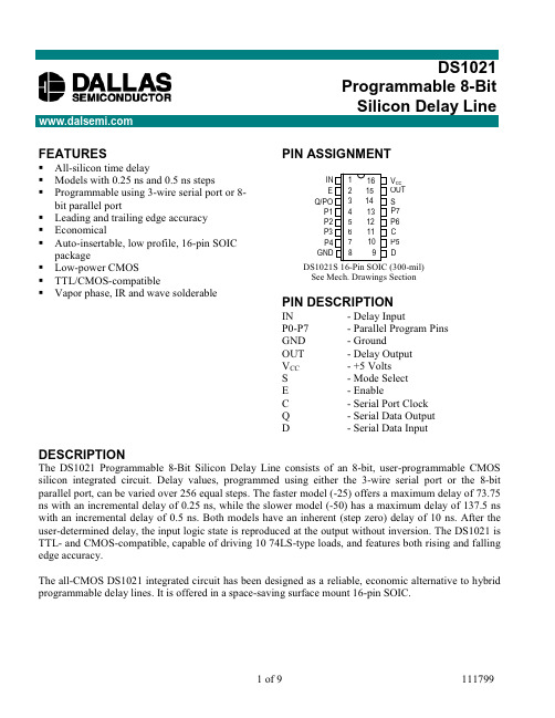
FEATURESAll-silicon time delayModels with 0.25 ns and 0.5 ns stepsProgrammable using 3-wire serial port or 8-bit parallel portLeading and trailing edge accuracy EconomicalAuto-insertable, low profile, 16-pin SOIC packageLow-power CMOS TTL/CMOS-compatibleVapor phase, IR and wave solderablePIN ASSIGNMENTPIN DESCRIPTIONIN - Delay Input P0-P7- Parallel Program Pins GND - Ground OUT - Delay Output V CC - +5 Volts S - Mode Select E - Enable C - Serial Port Clock Q - Serial Data Output D - Serial Data InputDESCRIPTIONThe DS1021 Programmable 8-Bit Silicon Delay Line consists of an 8-bit, user-programmable CMOSsilicon integrated circuit. Delay values, programmed using either the 3-wire serial port or the 8-bit parallel port, can be varied over 256 equal steps. The faster model (-25) offers a maximum delay of 73.75ns with an incremental delay of 0.25 ns, while the slower model (-50) has a maximum delay of 137.5 ns with an incremental delay of 0.5 ns. Both models have an inherent (step zero) delay of 10 ns. After the user-determined delay, the input logic state is reproduced at the output without inversion. The DS1021 is TTL- and CMOS-compatible, capable of driving 10 74LS-type loads, and features both rising and falling edge accuracy.The all-CMOS DS1021 integrated circuit has been designed as a reliable, economic alternative to hybrid programmable delay lines. It is offered in a space-saving surface mount 16-pin SOIC.Programmable 8-BitSee Mech. Drawings SectionIN E Q/PO P1P3P2GNDOUT P6P5DC P7V CC P4SPARALLEL MODE (S = 1)In the PARALLEL programming mode, the output of the DS1021 will reproduce the logic state of the input after a delay determined by the state of the 8 program input pins P0 - P7. The parallel inputs can be programmed using DC levels or computer-generated data. For infrequent modification of the delay value, jumpers may be used to connect the input pins to V CC and ground. For applications requiring frequent timing adjustment, DIP switches should be used. The enable pin (E) must be at a logic 1 in hardwired implementations.Maximum flexibility is obtained when the 8 parallel programming bits are set using computer-generated data. When the data setup (t DSE) and data hold (t DHE) requirements are observed, the enable pin can be used to latch data supplied on an 8-bit bus. Enable must be held at a logic 1 if it is not used to latch the data. After each change in delay value, a settling time (t EDV or t PDV) is required before input logic levels are accurately delayed.Since the DS1021 is a CMOS design, unused input pins (D and C) must be connected to well-defined logic levels; they must not be allowed to float.SERIAL MODE (S = 0)In the SERIAL programming mode, the output of the DS1021 will reproduce the logic state of the input after a delay time determined by an 8-bit value clocked into serial port D. While observing data setup (t DSC) and data hold (t DHC) requirements, timing data is loaded in MSB-to-LSB order by the rising edge of the serial clock (C). The enable pin (E) must be at a logic 1 to load or read the internal 8-bit input register, during which time the delay is determined by the last value activated. Data transfer ends and the new delay value is activated when enable (E) returns to a logic 0. After each change, a settling time (t EDV) is required before the delay is accurate.As timing values are shifted into the serial data input (D), the previous contents of the 8-bit input register are shifted out of the serial output pin (Q) in MSB-to-LSB order. By connecting the serial output of one DS1021 to the serial input of a second DS1021, multiple devices can be daisy-chained (cascaded) for programming purposes (Figure 3). The total number of serial bits must be eight times the number of units daisy-chained and each group of 8 bits must be sent in MSB-to-LSB order.Applications can read the setting of the DS1021 delay line by connecting the serial output pin (Q) to the serial input (D) through a resistor with a value of 1K to 10K ohms (Figure 2). Since the read process is destructive, the resistor restores the value read and provides isolation when writing to the device. The resistor must connect the serial output (Q) of the last device to the serial input (D) of the first device of a daisy-chain (Figure 3). For serial readout with automatic restoration through a resistor, the device used to write serial data must go to a high impedance state.To initiate a serial read, enable (E) is taken to a logic 1 while serial clock (C) is at a logic 0. After a waiting time (t EQV), bit 7 (MSB) appears on the serial output (Q). On the first rising (0 ĺ 1) transition of the serial clock (C), bit 7 (MSB) is rewritten and bit 6 appears on the output after a time t CQV. To restore the input register to its original state, this clocking process must be repeated eight times. In the case of a daisy-chain, the process must be repeated eight times per package. If the value read is restored before enable (E) is returned to logic 0, no settling time (t EDV) is required and the programmed delay remains unchanged.Since the DS1021 is a CMOS design, unused input pins (P1 - P7) must be connected to well-defined logic levels; they must not be allowed to float. Serial output Q/P0 should be allowed to float if unused.FUNCTION BLOCK DIAGRAM Figure 1SERIAL READOUT Figure 2DS1021CASCADING MULTIPLE DEVICES (DAISY CHAIN) Figure 3PART NUMBER TABLE Table 1DELAYS AND TOLERANCES (IN ns)PART NUMBERSTEP ZERO DELAY TIMEMAX DELAY TIME (NOM)DELAY CHANGE PER STEP (NOM)MAX DEVIATION FROM PROGRAMMED DELAYDS1020-2510 ± 273.750.25±6DS1020-5010 ± 2137.50.5±8DELAY VS. PROGRAMMED VALUE Table 2M I N D E L A Y (S T E P Z E R O )M A X D E L A YP A R A L L E L P O R TS E R I A L P O R T000000111P7MSB000000111P6BINARYPROGRAMMED VALUE000000111P5000000111P4000000111P3000011111P2001100011P1PART NUMBER010101101P0LSBDS1021-2510.0010.2510.5010.7511.0011.2573.2573.5073.75DS1021-5010.010.511.011.512.012.5136.5137.0137.5All delays in nanoseconds, referenced to input pin.ӣDS1021DS1021DS1021ӣDALLAS SEMICONDUCTOR TEST CIRCUIT Figure 4DS1021TEST SETUP DESCRIPTIONFigure 4 illustrates the hardware configuration used for measuring the timing parameters of the DS1021. The input waveform is produced by a precision pulse generator under software control. Time delays are measured by a time interval counter (20 ps resolution) connected to the output. The DS1021 serial and parallel ports are controlled by interfaces to a central computer. All measurements are fully automated with each instrument controlled by the computer over an IEEE 488 bus.TEST CONDITIONSINPUT:Ambient Temperature:25°C ± 3°CSupply Voltage (V CC): 5.0V ± 0.1VInput Pulse:High = 3.0V ± 0.1VLow = 0.0V ± 0.1VSource Impedance:50 ohms max.Rise and Fall Time: 3.0 ns max.(measured between 0.6V and 2.4V)Pulse Width:500 ns (DS1021–25)2 µs (DS1021–50)Period: 1 µs (DS1021–25)4 µs (DS1021–50)NOTE: Above conditions are for test only and do not restrict the operation of the device under other data sheet conditions.OUTPUT:Output is loaded with a 74F04. Delay is measured between the 1.5V level of the rising edge of the input signal and the 1.5V level of the corresponding edge of the output.ABSOLUTE MAXIMUM RATINGS*Voltage on Any Pin Relative to Ground-1.0V to +7.0VOperating Temperature0°C to 70°CStorage Temperature-55°C to +125°CSoldering Temperature260°C for 10 secondsShort Circuit Output Current50 mA for 1 second* This is a stress rating only and functional operation of the device at these or any other conditions above those indicated in the operation sections of this specification is not implied. Exposure to absolute maximum rating conditions for extended periods of time may affect reliability.DC ELECTRICAL CHARACTERISTICS(0°C to 70°C; V CC = 5.0V ± 5%) PARAMETER SYM TESTCONDITIONMIN TYP MAX UNITS NOTES Supply Voltage V CC 4.75 5.00 5.25V1 High Level InputVoltageV IH 2.2V CC + 0.5V1Low Level InputVoltageV IL-0.50.8V1Input LeakageCurrentI10.0V≤ V I≤ V CC-1.0 1.0µAActive Current I CC V CC=MAX;Period=1 µs30.0mA3High Level Output Current I OH V CC=MIN.V OH=2.7V-1.0mALow Level Output Current I OL V CC=MIN.V OL=0.5V8mA4AC ELECTRICAL CHARACTERISTICS(0°C to 70°C; V CC = 5V ± 5%) PARAMETER SYMBOL MIN TYP MAX UNITS NOTES Clock Frequency f C10MHzEnable Width t EW50ns Fig. 7, 8 Clock Width t CW50ns Fig. 8 Data Setup to Clock t DSC30ns Fig. 8 Data Hold from Clock t DHC10ns Fig. 8 Data Setup to Enable t DSE30ns Fig. 7 Data Hold from Enable t DHE20ns Fig. 7 Enable to SerialOutput Validt EQV50ns Fig. 8Enable to SerialOutput High Zt EQZ050ns Fig. 8Clock to SerialOutput Validt CQV50ns Fig. 8Clock to SerialOutput Invalidt CQX10ns Fig. 8 Enable Setup to Clock t ES50ns Fig. 8 Enable Hold from Clock t EH50ns Fig. 8 Parallel Input Validto Delay Validt PDV50µs Fig. 6(cont’d)PARAMETER SYMBOL MIN TYP MAX UNITS NOTESt PDX0nsParallel Input Changeto Delay InvalidEnable to Delay Valid t EDV50µsEnable to Delay Invalid t EDX0nsV CC Valid to Devicet PU100msFunctionalV CC Rise Time t VR20msInput Pulse Width t WI100% of OutputnsDelayInput to Output Delay t PLH, t PHL Table 2ns2 Input Period Period 2 (t WI)ns CAPACITANCE(T A = 25°C) PARAMETER SYMBOL MIN TYP MAX UNITS NOTES Input Capacitance C IN10pFTIMING DIAGRAM: SILICON DELAY LINE Figure 5TERMINOLOGYPeriod: The time elapsed between the leading edge of the first pulse and the leading edge of the following pulse.t WI (Pulse Width): The elapsed time on the pulse between the 1.5V point on the leading edge and the 1.5V point on the trailing edge, or the 1.5V point on the trailing edge and the 1.5V point on the leading edge.t RISE (Input Rise Time): The elapsed time between the 20% and the 80% point on the leading edge of the input pulse.t FALL (Input Fall Time): The elapsed time between the 80% and the 20% point on the trailing edge of the input pulse.t PLH (Time Delay, Rising): The elapsed time between the 1.5V point on the leading edge of the input pulse and the 1.5V point on the leading edge of the corresponding output pulse.t PHL (Time Delay, Falling): The elapsed time between the 1.5V point on the trailing edge of the input pulse and the 1.5V point on the trailing edge of the output pulse.TIMING DIAGRAM: NON-LATCHED PARALLEL MODE (S = 1, E = 1) Figure 6TIMING DIAGRAM: LATCHED PARALLEL MODE (S=1) Figure 7TIMING DIAGRAM: SERIAL MODE (S = 0) Figure 8TIMING DIAGRAM: POWER-UP Figure 9NOTES:1.All voltages are referenced to ground.2.@ V CC = 5V and 25°C. Delay accurate on both rising and falling edges within tolerances given inTable 1.3.Measured with output open.4.The “Q” output will only source 4 mA. This pin is only intended to drive other DS1021s.。
毕业设计 用于电动汽车的双向DC-DC变换器研究与仿真
毕业设计(论文)题目用于电动汽车的双向DC-D C交换器研究与仿真专业学生姓名班级学号指导教师指导单位日期: 年月日至年月日毕业设计(论文)原创性声明本人郑重声明:所提交的毕业设计(论文),是本人在导师指导下,独立进行研究工作所取得的成果。
除文中己注明引用的内容外,本毕业设计(论文)不包含任何其他个人或集体已经发表或撰写过的作品成果。
对本研究做出过重要贡献的个人和集体,均己在文中以明确方式标明并表示了谢意。
论文作者签名:日期:年月日摘要随着能源、环保等问题的日益突出,电动汽车成为近年来发展迅速的一种新型汽车,是21 世纪最具有发展前途的绿色清洁汽车。
电动汽车是用电池替代传统的汽油作为车载能源的,然而在现有的技术条件下,动力电池的性能是电动汽车发展的主要瓶颈。
双向DC-DC 变换器可以优化电动机控制、提高电动汽车整体的效率和性能。
针对双向DC-DC 变换器存在的开关损耗高等问题,本文研究了一种隔离型双向软开关DC-DC 变换器。
在介绍变换器工作原理的基础上,本文着重分析了电压、电流的变化规律,特别是推导出各开关元件实现软开关的条件及其数学表达式,并得到了实现软开关的通用条件。
最后通过Sab e r 软件对电路在两种模式下的稳态工况和软开关特性进行仿真研究,仿真结果证明根据该通用条件设计的变换器能够在大负载范围内实现软开关。
关键词: 双向DC-DC 变换器;PWM 控制:移相控制:软开关ABSTRACTEl ec tric Vehicl e(E V) b ec ome s a kind of n ew,fast-developing vehicle in th e last years,which ha s th e b est futureωa green vehicle,as 由e problems of energy and environment are b ecoming more and mor e se riou s in th e 21st centur予The energy in EV i s provid e d by storage batt eries instead of traditional gasoline and the d eve lopm en t of EV 町e limit e d by th e capacity of it s s tora ge batt eries with current t ec hnologi es. It can improv e 由e p er formance of th e s torage batteri es and th e working effi ci e ncy of driving sys t e m s by u s in g bidir ec tional DCIDC converter in El ec tric Vehicl e a t pr ese nt.A s oft sw itchin g bi-dir ec tional DCIDC converter was dev e loped to reduc esw itching lo sses. Op e ration principl e of the proposed converter i s introduced. Th e s oft sw itching principle i s also introduced briefly. On th e ba s i s of the operational analy s i s,th e characteristic of the voltage and current i s illu s trat e d and the ZVS conditions of th e diff e r e nt s witch es ar e al so given in d e tail. Wh at i s more,th e formula of th e univer s al ZVS condition for all th e sw itch es i s speci ally d e duced to s扫nplify th e four ZVS conditions into one formula for the convenience of th e de s ign. An d the s t ea dy s tate conditions and s oft sw itchin g characteristic of the circuit in tho se two op e rating mode,are d em on s trated by the Sab e r,expe rimental results obtain e d from th e converter ares hown to veri句r the validity of th e univ e r s al ZVS condition.Key words: Bi-Dir ec tional DCIDC converter; PWM control; Pha se-s hlft control;Soft sw itching目录第一章绪论...................................................."11.1课题背景和意义.................................................11.2双向DC-DC变换器概述..........................................21.2.1双向DC-DC变换器的原理 (2)1.2.2双向DC-DC变换器的拓扑结构 (3)1.2.3双向DC-DC变换器的控制方式 (5)1.3双向DC-DC变换器在电动汽车上的应用 (6)1.4 论文的主要研究内容和结构.......................................9第二章双半桥双向DC-DC 变换器工作原理与结构分析 (11)2.1电动汽车双向DC-DC变换器.....................................112.1.1燃料电池电动汽车能量管理系统..............................112.1.2蓄电池燃料电池电动汽车动力系统工作模式分析 (12)2.2双半桥双向DC-DC拓扑结构的选择与分析 (12)主功率拓扑的选择 (12)2.2.2控制方案选择 (13)2.2.3拓扑电路的分析 (13)2.3变换器等效电路 (14)2.4变换器换流分析 (16)正向工作模式 (16)2.4.2反向工作模式 (18)正向/反向模式下的软开关条件 (19)2.6本章小结 (19)第三章双半桥双向DC-DC 变换器稳态特性分析与设计 (20)3.1双向变换器输出特性分析 (20)3.2变换器设计....................................................22变压器漏感选择 (22)3.2.2开关管应力分析 (23)3.2.3输入电感设计 (24)3.3本章小结 (24)第四章仿真验证 (25)结束语 (28)致谢 (29)参考文献 (30)第一章绪论1.1课题背景和意义当今世界,环境和能源问题成为世界各国关心的热点问题。
LM27402:DC/DC转换器

MA 8 5 X 9 2的输入 电源可 低至 25 . V,有效 延长器 件工作 时 度 范围。内置偏压 电源副稳压器 ,内置 的高电流 MOS E FT
间 ,支持 较宽 范围 的电池类 型 。通过 I I E实现 动态 电 栅极驱 动器配备 自适应 死区时间控制功能 ,提供 3 A的负 C接 l 0 还可 支持可编程软启动 、 跟踪及预偏压启动等功能 。 压 调节 ,可将 输 出 电压设 置在 7 0 7 mV- .0 14 V之 间 ,步长 载 电流 ,
决方案 。H级版本经过测 试 ,保证至 1 O 5 ℃的最高结温 。
Li ar ww w.i arc ne 1ne , om n c
可与多种基于 S 的主机 器件 直接连接 。 PI 该 系列器 件的 引脚兼容特性使 设计人 员在更改 分辨率
时无需重新设计 电路板或控制软 件。工作在 0 - 1 5c ℃ + 2 o
M X 1O A 112系 列 A C 具 有 7 . BS R和 7 d D 05 N d 0B
3 mm D N一0封装和高开关频率允许使用小型的外 SIAD( mm X3 F 1 N 最差工作条件下 ) ,在省 电的 同时不会降低器件性
部 电感器和 电容 器 ,可提供 占板面积 紧凑和热效率 高的解 能 。数 字接 口工 作在 15  ̄ .V电压 ,无 需 电平转换器 即 .V 36
为 1 mY。可 以工 作 在 固定频 率 (.5 z WM模 式 或 0 32 MH )P M2 4 2芯片有两种 封装 可供选择 ,包括 1 70 6引脚更强
省 电模式 , 也可将器件同步至外部系统 时钟 , 以降低 E 。 MI
散 热能 力 的 T S S OP封 装和 4 mm × mm 的 L P封 装。美 4 L
应用在嵌入式计算机中的DC/DC转换器——可以在高达85℃温度下满载荷输出
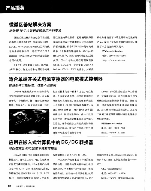
应用在嵌入式计算机中的 D / e转换器 eD
NG 系 列 DC/ A DC转 换 器 采 用 同 步 负载调整率分 别为 0 2 .%和 1 5 .%。 整 流 技 术 , 率 高 达 9 %, 以 在 高 达 8 效 5 可 5 封 装 的 尺 寸 是 2 .9 m 0 9 rm , 14 r X2 .6 a a 高
整 器 , 省 0 5 l 无 负 载 功 耗 ,芯 片 节 .~ W
一
个芯片上 , 采用BC 双极 晶体管 一场 能 、提 高 抗 噪性 能的 电流 感应 前 缘 消 D(
效应 MOS晶体 管 一双扩 散 O S晶体 管) 隐 、过 压禁 用 闭 锁 或 过 热 关 机 ,以 及 当
离 线技术 , 压高达 70 耐 0 V,由一 个 低 压 二次 侧二极管故障短路 时输 出电流保护
适合单端开关式电源变换器的电流模式控制器
符合多 种节能标 准 ,性能不受 影响
L6 6 6 8电 流 模 式 PW M 控 制 器 与 的高 压技术 结合一种 多片方法 ,可以集 L6 6 的 功 能 还 包 括 三 种 工 作 模 68
P FC控制 器的接 口是 智能化的 ,当负载 成 一 个 高 压 启 动 系统 ,与 经 过 整流 的 主 式 、可编程软 启动 、在 占空 比高于 5 % 0 低于某一 个闽值时 ,接 口自动关 断预调 电流 电压直接 相连 。高 压发生 器单 独在 时 确 保稳 定 操 作 的斜 率 补 偿 、禁 用 功
8 2
今Hale Waihona Puke 电子 ・2 0 年 1 06 月S TMi r e e t 0 i s c 0 lc r n c
电 话 :0 0 8 9 3 8 l—8 0 -7 9
- 1、下载文档前请自行甄别文档内容的完整性,平台不提供额外的编辑、内容补充、找答案等附加服务。
- 2、"仅部分预览"的文档,不可在线预览部分如存在完整性等问题,可反馈申请退款(可完整预览的文档不适用该条件!)。
- 3、如文档侵犯您的权益,请联系客服反馈,我们会尽快为您处理(人工客服工作时间:9:00-18:30)。
Shutdown
As discussed in the previous section, if the OCSET/SD pin or ENABLE pin is pulled down and held below 0.8V, the regulator will be turned off. The MOSFET gates are immediately pulled low. Figure 3 shows the shutdown profile of the regulator under full load.
1
CAUTION: These devices are sensitive to electrostatic discharge; follow proper IC Handling Procedures. 1-888-INTERSIL or 321-724-7143 | Intersil (and design) is a registered trademark of Intersil Americas Inc. Copyright © Intersil Americas Inc. 2002. All Rights Reserved
All evaluation boards have the same output filter, compensation components and MOSFETs. They are configured for an output of 2.5V with a maximum load of 5A. The ISL6526 evaluation boards have a fixed output while the ISL6527 evaluation boards allow the use of a potentiometer to adjust the output voltage from 0.75V to 3.0V. Unless otherwise noted, this application note assumes that the output of the ISL6527 evaluation board is 2.5V.
ISL6527EVAL2
16 ld MLFP
Connect the positive lead of the adjustable bench power supply to the 3.3V post (J1). Connect the ground lead of the supply to GND post (J2). OUTPUT LOADING - SOURCING CURRENT Connect the positive terminal of the load to the VOUT post (J3). Connect the return terminal of the same load to the GND post (J4). OUTPUT LOADING - SINKING CURRENT CAUTION: The return terminal of the load must float for this to work properly.
Power and Load Connections
16 ld MLFP 14 ld SOIC
ISL6526EVAL2 ISL6527EVAL1
There are 2 sets of terminals that are used to supply the input voltage and load the output. INPUT VOLTAGE
ISL6526/27 Reference Designs
The ISL6526/27 evaluation board highlights the operation of the ISL6526 and ISL6527 ICs in an embedded application. There are five evaluation boards from which to choose.
Recommended Test Equipment
To test the functionality of the ISL6526 or ISL6527, the following equipment is recommended: - An adjustable 0 - 5V, 5A capable bench power supply - An electronic load - Four channel oscilloscope with probes - Precision digital multimeter
The ISL6526EVAL1 board is built with the ISL6526CB and shipped with an ISL6526ACB sample piece. Evaluation of the ISL6526CB can be performed immediately. If evaluation of the ISL6526ACB is desired, then it is a simple matter of replacing the controller. The ISL6527EVAL1 is shipped with the ISL6527CB and shipped with an ISL6527ACB sample piece. As with the ISL6526CB and ISL6526ACB, the parts are interchangeable. The ISL6526EVAL2 and ISL6527EVAL2 are ready for evaluation without any modifications.
AN1021
To observe the output while the regulator sinks current, connect the positive terminal of the load to the 3.3V post (J1). Connect the return terminal of the same load to the VOUT post (J3).
Hale Waihona Puke StartupThere are two distinct start up methods for both the ISL6526 and ISL6527 regulators. The first method is invoked through the application of power to the IC. The soft-start feature allows for a controlled rise of the output once the Power On Reset (POR) threshold of the input voltage has been reached. Figure 1 shows the start up profile of the regulator in relation to the start up of the 3.3V input supply and the bias supply generated by the charge pump. Both the ISL6526 and ISL6527, whether switching at 300 or 600kHz, will have the same start up profile as shown in Figure 1.
®
Embedded DC-DC Converters Using ISL6526 and ISL6527 PWM Controller ICs
Application Note
June 2002 AN1021
PRELIMINARY
Introduction
The ISL6526 and the ISL6527 provide power control and protection for applications requiring low voltage and high power. Both ICs can be biased from voltages between 3.3V and 5V. The ISL6526 and ISL6527 contain a high performance error amplifier, a high accuracy reference, a fixed 300kHz or 600kHz internal oscillator, over-current protection circuitry, and two MOSFET drivers for use in synchronous-rectified buck converters. Both the ISL6526 and the ISL6527 are capable of regulating the output voltage while the DC-DC converter is sinking current. The ISL6527 also allows for an external reference to be used. All these features are packaged in a small 14-lead SOIC or a 16-lead 5x5[mm] MLFP. More complete descriptions of the ISL6526 and the ISL6527 can be found in their respective datasheets [1, 2]. This application note details the ISL6526 and ISL6527 in DC-DC converters for applications requiring a tightly regulated, fixed output voltage. Low-cost applications requiring a DC-DC converter can benefit from one of the designs presented in this application note
