TL99-0050-018中文资料
中药配合放化疗治疗脑转移瘤68例临床分析
作者单位 :30 3 001 太原 , 山西省中西医结合 医院肿瘤科
2 0. 4
( 稿 日期 :0 1 92 ) 收 2 1- .6 0
中药配合放化 疗 治疗脑 转移瘤 6 8例临床 分 析
田 丽 丽
脑转移瘤 系继发于癌症的颅 内最常见 的肿瘤。脑转移瘤 不治疗平均生存期 4周 , 为癌症患者死亡的主要原 因。 由于脑 转移瘤患 者其原发癌症 多为 晚期, 且脑转移瘤 大多 为实质性 ,
・
9 ・ 8
中国药物与 l床 2 1 年 1 临 02 月第 l 卷第 1 C i s R m de &Ci c , n a 1,o 1,o 2 期 h ee e e i n s li J ur2 2 12 . nsa y0 V . N 1
氧而杀灭增生 活跃 的细胞 。导致 H V感染 的组织坏死和凋 P 亡, 起到 良好的治疗效果 , 但对正常组织却损 伤轻微 。王秀丽 和徐世正 [ 1 ] 研究发现 , 该治疗方法不仅可 以治疗临床 肉眼可 见的疣体 , 还可 以治疗 HP V感染的亚临床病灶和潜伏感染 。 这也是其治疗效果较好 的原 因之一 。 常规的治疗可去 除肉眼 可见的疣体 , 达到“ 点清除” 的效果 , A A P T方法在药量 而 L .D
义。
疗 前后行 为状况评 分与西 医组 比较 , 差异有统计 学意义 ( < P 0 5, . ) 中西 医组能够 明显改善患者生存质量 。 0 23 2 . 组治疗 1 以上生存率及平均生存期 的比较 : 年 见表 2 。 中西 医组 治疗前后平 均生存期 与西医组 比较 差异有统计 学 意义( < . ) 中西 医组能够 明显延长患者生存期 。 P0 5, 0
BK60-005
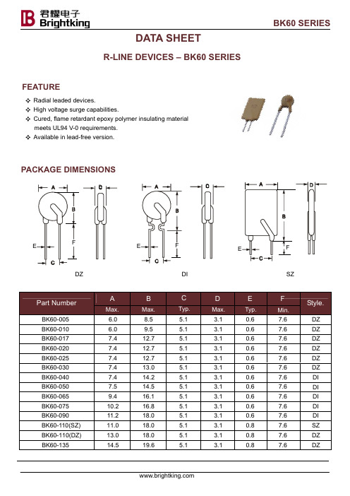
C
Typ. 5.1 5.1 10.5 10.5 10.5
D
Max. 3.1 3.1 3.1 3.1 3.1
BK60 SERIES
E
F
Style.
Typ.
Min.
0.8
7.6
DZ
0.8
7.6
DZ
0.8
7.6
DZ
0.8
7.6
DZ
0.8
7.6
DZ
ELECTRICAL CHARACTERISTICS
Part Number
100.00
BK60-160 BK60-185 BK60-250
2.18
1.90
1.60
1.44
1.30
1.15
1.01
0.86
0.64
2.52
2.20
1.85
1.67
1.50
1.33
1.17
1.00
0.743.ຫໍສະໝຸດ 02.982.50
2.25
2.03
1.80
1.58
1.35
1.00
BK60-300 BK60-375
4.08
3.57
3.00
2.70
2.43
2.18
1.89
1.62
1.20
5.10
4.46
3.75
3.38
3.04
2.70
2.36
2.03
1.50
TEST PROCEDURES AND REQUIREMENT
Test
Resistance Time to Trip Hold Current Trip Cycle Life Trip Endurance
V23079中文资料
P2 RelayThe Best Rela ytion90012 pole telecom relay, polarized,Through Hole Type (THT) orSurface Mount Technology (SMT),Relay types: non-latching with 1 coil latching with 2 coils latching with 1 coilFeatures– Standard telecom relay (ringing and test access)– Slim line 15 x 7.5 mm, 0.590 x 0.295 inch – Switching current 5 A– 2 changeover contacts (2 form C / DPDT)– Bifurcated contacts – Immersion cleanable– High sensitivity results in low nominal power consumption 140 mW for non-latching and latching with 2 coils 70 mW for latching with 1 coil – For single coil version:- Surge voltage resistance between contact and coil for single coil version:- 2.5 kV (2 / 10 µsec) meets the Bellcore Requirement GR-1089 - 1.5 kV (10 / 160 µsec) meets FCC Part 68Typical applications– Communications equipmentlinecard application (ringing and test access) PABXVoice over IP – Office equipment– Measurement and control equipment – Automotive equipmentCAN bus, keyless entry, speaker switch – Medical equipment – Consumer electronics Set Top Boxes, HiFiOptions– 1500 Vrms between open contacts – Temperature range up to 105° CUL 508 File No. E111441UL 60950QC 160504-CH0003CECC 811-54-003Insulation category:Supplementary insulation according IEC / EN 60950Working voltage ³ 300 Vrms Mains supply voltage ³ 250 Vrms Repetitive peak voltage 2500 V Pollution degree: Internal: 1 External: 2Flammability classification: V-0Maximum operating temperature: 85 °CIEC/EN60950 IEC Ref. Cert. No. CH 2171DimensionsTHT THT SMT long terminals SMT long terminals SMT short terminals SMT short terminals V23079-x1xxx-B301 V23079-x2xxx-B301 V23079-x1xxx-B301 V23079-x2xxx-B301V23079-x1xxx-B301 V23079-x2xxx-B301 standard coil overmolded coil standard coil overmolded coil standard coil overmolded coilmm inch mm inch mm inch mm inch mm inch mm inchL 14.5 ± 0.1 0.570 ± 0.004 14.5 ± 0.1 0.570 ± 0.00414.5 ± 0.1 0.570 ± 0.00414.5 ± 0.10.570 ± 0.00414.5 ± 0.1 0.570 ± 0.00414.5 ± 0.10.570 ± 0.004 W 7.2 ± 0.1 0.283 ± 0.004 7.2 ± 0.1 0.283 ± 0.0047.2 -0.15 0.283 ± 0.0047.2 -0.15 0.283 ± 0.0047.2 -0.15 0.283 ± 0.0047.2 -0.15 0.283 ± 0.004 H9.8 ± 0.1 0.385 ± 0.004 9.5 ± 0.1 0.374 ± 0.00410.4 ± 0.15 0.409 ±0.006 9.9 ± 0.1 0.390 ± 0.00410.4 ± 0.150.409 ±0.006 9.9 ± 0.1 0.390 ± 0.004 T 3.25 - 0.25 0.128 -0.010 3.25 - 0.25 0.128 -0.010N/A N/A N/A N/A N/A N/A N/A N/AT1 N/A N/A N/A N/A 5.52 ±0.15 0.217 ±0.006 5.52 0.217 ±0.006 5.52 0.217 ±0.006 5.52 0.217 ±0.006 T2 N/A N/A N/A N/A 9.4 ±0.15 0.370 ±0.006 9.4 ±0.15 0.370 ±0.006 7.4 ±0.15 0.291 ±0.006 7.4 ±0.15 0.291 ±0.006 Tw0.5 ± 0.05 0.020 ±0.002 0.5 ± 0.05 0.020 ±0.0020.5 ± 0.05 0.020 ±0.002 0.5 ± 0.050.020 ±0.002 0.5 ± 0.05 0.020 ±0.002 0.5 ± 0.050.020 ±0.002 S 0.55 - 0.15 0.022 -0.0060.45 0.018 ±0.002N/A N/A N/A N/A N/A N/A N/A N/ATHT VersionNote: Hole for pin 6 and 7only for latching with 2 coilsBasic grid 2.54 mmLong terminalsSMT VersionShort terminalsNote: Solder pad for pin 6 and 7only for latching with 2 coilsNote: Solder pad for pin 6 and 7only for latching with 2 coilsLong terminals Short terminalsTerminal assignmentRelay - top viewLatching type, 2coilsreset condition Mounting hole layoutView onto the component side of the PCBSolder pad layoutView onto the component side of the PCBNon-latching type,not energized conditionLatching type, 1 coilreset conditionnon-latching 1 coilA1xxx/D1xxx/G1xxx A2xxx/D2xxx/G2xxx3 2.25 6.50 0.30 140 64.3 0084 3.00 8.70 0.40 140 114 016 4.5 3.375 9.80 0.45 140 145 011 5 3.75 10.90 0.50 140 178 0016 4.5 13.00 0.60 140 257 002 9 6.75 19.60 0.90 140 578 006 12 9.00 26.15 1.20 140 1029 003 24* 18.00 52.30 2.40 140 4114 005 3 2.25 6.50 2.25 140 64.3 208 4.5 3.375 9.80 3.375 140 145 211 5 3.75 10.90 3.75 140 178 201 6 4.5 13.00 4.50 140 257 202 9 6.75 19.60 6.75 140 578 206 12 9.00 26.15 9.00 140 1029 203 24 18.00 52.30 18.00 140 4114 205latching 2 coilslatching 1 coil3 2.25 9.20 2.25 70 128 108 4.5 3.375 13.85 3.375 70 289 111 5 3.75 15.33 3.75 70 357 101 6 4.5 18.50 4.50 70 514 102 9 6.75 27.75 6.75 70 1157 106 12 9.00 37.00 9.00 70 2057 103 24 18.00 74.00 18.00 70 8228 105* 24 V only in A1xxx/D1xxx/G1xxxFurther coil versions are available on request.Ambient temperature t amb [°C]B1xxx/E1xxx/H1xxxC1xxx/F1xxx/J1xxxU I = Minimum voltage at 23° C after pre-energizing with nominal voltage without contact current U II = Maximum continous voltage at 23°The operating voltage limits U I and U II depend on the temperature according to the formula:U I tamb = K I · U I 23° C and U II tamb = K Il · U Il 23° Ct amb = Ambient temperatureU I tamb = Minimum voltage at ambient temperature, t amb U II tamb = Maximum voltage at ambient temperature, t amb k I , k II = Factors (dependent on temperature), see diagramAll data refers to 23° C unless otherwise specified.Recommended soldering conditionsSoldering conditions according CECC 00802Vapor Phase Soldering: Temperature/Time Profile (Lead Temperature)Infrared Soldering: Temperature/Time Profile (Lead Temperature)Time (s)Time (s)T e m p e r a t u r e °CT e m p e r a t u r e °CTube for THT version - 50 relays per tube, 2000 relays per boxTape and reel for SMT version with long terminals - 400 relays per reel, 2000 relays per boxTape and reel for SMT version with short terminals - 500 relays per reel, 2500 relays per boxReel dimensionDimensions in mmPackingV23079-A1001-B301 0-1393788-3 V23079-A1002-B301 0-1393788-8 V23079-A1003-B301 1-1393788-1 V23079-A1005-B301 1-1393788-6 V23079-A1006-B301 2-1393788-0 V23079-A1008-B301 2-1393788-2 V23079-A1011-B301 2-1393788-4 V23079-A2001-B301 3-1393789-5 V23079-A2002-B301 3-1393789-6 V23079-A2003-B301 3-1393789-7 V23079-A2005-B301 0-1393790-2 V23079-A2006-B301 3-1393789-8 V23079-A2008-B301 6-1419120-6 V23079-A2011-B301 3-1393789-9 V23079-B1201-B3013-1393788-3 V23079-B1202-B3013-1393788-5 V23079-B1203-B3013-1393788-6 V23079-B1205-B3013-1393788-7 V23079-B1206-B3013-1393788-9 V23079-B1208-B3014-1393788-1 V23079-B1211-B3014-1393788-2 V23079-C1101-B301 4-1393788-5 V23079-C1102-B301 4-1393788-7 V23079-C1103-B301 4-1393788-8 V23079-C1105-B301 5-1393788-0 V23079-C1106-B301 5-1393788-1 V23079-C1108-B301 5-1393788-3 V23079-C1111-B301 5-1393788-4 V23079-D1001-B301 5-1393788-5 V23079-D1002-B301 5-1393788-6 V23079-D1003-B301 5-1393788-7 V23079-D1005-B301 5-1393788-8 V23079-D1006-B301 5-1393788-9 V23079-D1008-B301 6-1393788-1 V23079-D1011-B301 6-1393788-2 V23079-D2001-B301 4-1393789-3 V23079-D2002-B301 4-1393789-4 V23079-D2003-B301 4-1393789-5 V23079-D2006-B301 4-1393789-6 V23079-D2008-B301 4-1393789-7 V23079-D2011-B301 4-1393789-8V23079-E1201-B3016-1393788-8 V23079-E1202-B3010-1393789-5 V23079-E1203-B3016-1393788-9 V23079-E1205-B3017-1393788-0 V23079-E1206-B3010-1393789-9 V23079-E1208-B3017-1393788-1 V23079-E1211-B3017-1393788-2 V23079-F1101-B301 7-1393788-3 V23079-F1102-B301 1-1393789-0 V23079-F1103-B301 7-1393788-4 V23079-F1105-B301 1-1393789-1 V23079-F1106-B301 1-1393789-2 V23079-F1108-B301 7-1393788-5 V23079-F1111-B301 1-1393789-4 V23079-G1001-B301 7-1393788-6 V23079-G1002-B301 1-1393789-5 V23079-G1003-B301 7-1393788-7 V23079-G1005-B301 7-1393788-8 V23079-G1006-B301 1-1393789-6 V23079-G1008-B301 8-1393788-0 V23079-G1011-B301 1-1393789-7 V23079-G2001-B301 4-1393789-9 V23079-G2002-B301 5-1393789-0 V23079-G2003-B301 5-1393789-1 V23079-G2006-B301 5-1393789-3 V23079-G2008-B301 5-1393789-4 V23079-G2011-B301 5-1393789-5 V23079-H1201-B301 2-1393789-0 V23079-H1202-B301 2-1393789-1 V23079-H1203-B301 8-1393788-3 V23079-H1205-B301 2-1393789-2 V23079-H1206-B301 2-1393789-3 V23079-H1208-B301 2-1393789-4 V23079-H1211-B301 8-1393788-4 V23079-J1101-B301 2-1393789-5 V23079-J1102-B301 2-1393789-6 V23079-J1103-B301 2-1393789-7 V23079-J1105-B301 2-1393789-8 V23079-J1108-B301 2-1393789-9 V23079-J1111-B301 3-1393789-0Relay Code TycoPart Number Relay Code TycoPart NumberOrdering Information Middle block of relay codeV23079-yyxxx-B301yy : See table belowxxx : See coil table on page 4yy DescriptionA1 THT, non latching, standard coilA2 THT, non latching, overmolded coil B1 THT, latching, 2 standard coilsC1 THT, latching, 1 standard coil D1 SMT, long pins, non latching, standard coil D2 SMT, long pins, non latching, overmolded coilE1 SMT, long pins, latching, 2 standard coils F1 SMT, long pins, latching, 1 standard coilG1 SMT, short pins, non latching, standard coil G2 SMT, short pins, non latching, overmolded coilH1 SMT, short pins, latching, 2 standard coils J1 SMT, short pins, latching, 1 standard coilDimensionsSMT short terminals V23079-G2xxx-X0xx overmolded coilmm inchL 14.5 ± 0.1 0.570 ± 0.004 W 7.2 -0.15 0.283 ± 0.004 H9.9 ± 0.1 0.390 ± 0.004 T N/A N/AT1 5.52 0.217 ±0.006 T2 7.4 ±0.15 0.291 ±0.006 Tw0.5 ± 0.05 0.020 ±0.002 S N/A N/ASMT Versionnon-latching1 coilV23079-5 3.75 10.90 0.50 140178 G2001-X0716 4.50 13.00 0.60 140257 G2002-X0729 6.75 19.60 0.90 140578 G2006-X07312 9.00 26.15 1.20 140 1029 G2003-X074 This supplementary data sheet refers to the basic data sheet of the P2 relay series (V23079) with following additions:-Dielectric strength 1500 Vrmsbetween open contacts - as well as between coil and contacts and between adjacent contact sets-Only non-latching types available-SMT version with short terminals as preferred type-mechanical and electrical endurance typ. 106 operationsOption: high dielectric between open contacts (overmolded coil)V23079-G2001-X071 0-1422006-1V23079-G2002-X072 0-1422006-2V23079-G2006-X073 0-1422006-3V23079-G2003-X074 0-1422006-4Relay Code TycoPart NumberOrdering InformationNote: Solder pad for pin 6 and 7only for latching with 2 coilsSolder pad layoutIM Relays4th generation slim line – low profile polarized 2 c/o telecom relay with bifurcated contacts, available as non latching or latching relay with1 coil. Nominal voltage range from 1.5... 24 V, coil power consumption of 140... 200 mW, latching relays with 1 coil 100 mW. The IM relayis available as through hole and surface mount type (J-Legs and Gull Wings) and capable to switch loads up to 60 W/62,5 VA. Dielectric strength fulfills the Bellcore requirements according GR 1089 (2,5 kV – 2 / 10 µs) and FCC part 68 (1,5 kV – 10 / 160 µs). The IM relay is CECC/IECQ approved and certified in accordance with IEC/EN 60950 and UL1950. Dimensions approx. 10 x 6 mm board space and5.65 mm height.P2 Relays3rd generation polarized 2 c/o telecom relay with bifurcated contacts, available as non latching or latching relay with 1 or 2 coils. Nominal voltage range from 3 ... 24 V, coil power consumption 140 mW, latching relays with 1 coil 70 mW. The P2 Relay is available as through hole or surface mount type and capable to switch currents up to 5A. Dielectric strength fulfills the Bellcore requirements according GR 1089 (2,5 kV – 2 / 10 µs) and FCC part 68 (1,5 kV – 10 / 160 µs). Dimensions approx. 15 x 7,5 mm board space and 10 mm height.FX Relays3rd generation polarized 2 c/o telecom relay with bifurcated contacts, available as non latching or latching relay with 1 coil. Nominal voltage range from 3 ... 48 V, coil power consumption of 80 ... 260 mW for the high sensitive version, 140... 300 mW for the standard version, latching relays with 1 coil 100 mW. The FX2 relay is available as through hole type and capable to switch loads up to 60 W/62,5 VA. Dielectric strength fulfills the Bellcore requirements according GR 1089 (2,5 kV – 2 / 10 µs) and FCC part 68 (1,5 kV – 10 / 160 µs). The FX2 is CECC/ IECQ approved and certified in accordance with IEC/EN 60950 and UL1950. Dimensions approx. 15 x 7,5 mm board space and 10,7 mm height.FT2 / FU2 Relays3rd generation non polarized, non latching 2 c/o telecom relay with bifurcated contacts. Nominal voltage range from 3 ... 48 V, coil power consumption 200 ... 300 mW. Most sensitive 48 V relay. Available as through hole and surface mount type. Dielectric strength fulfills the Bellcore requirements according GR 1089 (2,5 kV – 2 / 10 µs) and FCC part 68 (1,5 kV – 10 / 160 µs). The FT2/FU2 is CECC/IECQ approved and certified in accordance with IEC/EN 60950 and UL1950. Dimensions approx. 15 x 7,5 mm board space and 10 mm height.FP1 Relays3rd generation polarized 2 c/o telecom relay with bifurcated contacts, available as non latching or latching relay with 1 or 2 coils. Nominal voltage range from 3 ... 48 V, coil power consumption of 80 ... 260 mW for the high sensitive version, 140... 300 mW for the standard version, latching relays with 1 coil 100 mW.. The FP1 Relay is available as through hole type and capable to switch loads up to30 W/62,5 VA. Dielectric strength fulfills FCC part 68 (1,5 kV – 10 / 160 µs). The FP2 is CECC/IECQ approved. Dimensions approx.14 x 9 mm board space and 5 mm height.MT2 / MT42nd generation non polarized, non latching 2 c/o and 4 c/o telecom and signal relay with bifurcated contacts. Nominal voltage range from 4.5 ...48 V, coil power consumption 150/200/300/400 and550 mW, and 300 mW (MT4). Dielectric strength fulfills the requirements according FCC part 68 (1,5 kV – 10 / 160 µs) for both and the Bellcore requirements according GR 1089 (2,5 kV – 2 / 10 µs) the MT4 only.Dimensions MT2 approx. 20 x 10 mm board space and 11 mm height, MT4 approx. 20 x15 mm board space and 11 mm height.D2n Relays2nd generation non polarized 2 c/o relay for telecom and various other applications. Nominal voltage range from 3 ... 48 V, coil power consumption from 150 .... 500 mW. The D2n relay is capable to switch currents up to 3 A. Dielectric strength fulfills the requirements according FCC part 68 (1,5 kV – 10 / 160 µs). Dimensions approx.20 x10 mm board space and 11,5 mm height.P1 RelaysExtremely sensitive, polarized 1 c/o relay with bifurcated contacts for a wide range of applications, available as non latching or latching relay with 1 or 2 coils. Nominal voltage range from 3 ... 24 V, coil power consumption 65 mW, latching relays with 1 coil 30 mW. The P1 relay is available as through hole or surface mount type and capable to switch currents up to 1 A. Dielectric strength fulfills the requirements according FCC part 68 (1,5 kV – 10 / 160 µs). Dimensions approx.13 x 7,6 mm board space and 7 mm height for THT or 8 mm height for SMT version.W11 RelaysLow cost, non polarized 1 c/o relay for various applications. Nominal voltage range from 3 ... 24 V, coil power consumption 450 mW, sensitive versions 200 mW. The W11 relay is capable to switch currents up to 3 A. Dielectric strength 1000 Vrms. Dimensions approx. 15,6 x 10,6 mm board space and 11,5 mm height.Reed RelaysHigh sensitive, non polarized relay for telecom and various other applications, available with 1 n/o, 2 n/o or 1c/o contacts. Nominal voltage range from 5 ... 24 V, coil power consumption 50...280 mW for 1 n/o and 125 ... 280 mW for 2 n/o or 1 c/o versions. Reedrelays are available in DIP or SIL housing and capable to switch currents up to 0,5 A. Integrated diode and/or electrostatic shield optional. Dielectric strength 1500 Vdc. Dimensions approx. 19,3 x 7 mm board space and 5 ... 7,5 mm height for DIP or 19,8 x 5 mm board space and 7,8 mm height for SIL version.Cradle RelaysExtremely reliable and mature relay family of 1st generation for various signal switching applications. Available as non polarized, polarized/ latching and relay with AC coil. The benefit is the possibility of combining various contact sets from 1 up to 6 poles, single and bifurcated contacts, different contact materials with a coil voltage range from 1,5 Vdc to 220 Vac. Cradle relays are available as dust protected and hermetically sealed versions, with plug in or solder terminals and are capable to switch currents up to 5 A. Forcibly guided (linked) contact sets optional. Dielectric strength 500 Vrms. Dimensions from approx. 19 x 24 to 19x35 mm board space and30 mm height.Other RelaysWe offer a variety of different relay families for maintenance and replacement purposes. These relays are up to 60 years old now, such as Card Relay SN (V23030 / V23031 series), Small General Purpose Relay (V23006 series), Small Polarized Relay (V23063 (V23067)and V23163 ... V23167 series). Accessories like sockets, hold down springs, etc. optional.HF3 RelayHigh performance low cost RF relay with excellent RF characteristics. Available with an impedance of 50 and 75 Ohm. Suitable for frequen-cies up to 3 GHz. Actually smallest RF relay available combining small size, excellent RF performance and SMD solderability. Available as non latching or latching relay with 1 or 2 coils and a nominal coil voltage range from 3 ... 24 V, coil power consumption 140 mW, latching relays with 1 coil 70 mW. Dimensions 14.6 x 7.3 x 10 mm.Tyco Electronics AXICOM Ltd.Seestrasse 295 - P.O. Box 220CH-8804 Au-Wädenswil / Switzerland Phone +41 1 782 9111Fax +41 1 782 9080E-mail: axicom@ Tyco Electronics Corporation POB 3608,Harrisburg, PA 17105, USA Phone +001 800-522-6752Tyco Electronics EC Trutnov s.r.o.Komenského 821CZ-541 01 Trutnov / Czech Republic E-mail: axicom@ Tyco Electronics AMP GmbHPaulsternstrasse 26D-13629 Berlin / GermanyPhone +49 30 386 38260Fax +49 30 386 38569E-mail: axicom@ F e b r u a r y 2003 R e v . 2.0811元器件交易网。
TLC081中文资料

Copyright 2000−2004 Texas Instruments Incorporated
1
元器件交易网
SLOS254D − JUNE 1999 − REVISED FEBRUARY 2004
TLC080, TLC081, TLC082, TLC083, TLC084, TLC085, TLC08xA FAMILY OF WIDEĆBANDWIDTH HIGHĆOUTPUTĆDRIVE SINGLE SUPPLY OPERATIONAL AMPLIFIERS
−40°C to 125°C
† This package is available taped and reeled. To order this packaging option, add an R suffix to the part number (e.g., TLC084CDR).
2
SLOS254D − JUNE 1999 − REVISED FEBRUARY 2004
D Wide Bandwidth . . . 10 MHz D High Output Drive D D D D D D D
PMC150, PMS150 datasheet V005_CN

PMC150/PMS150 系列
8 位 IO 类型单片机
重要声明
应广科技保留权利在任何时候变更或终止产品,建议客户在使用或下单前与应广科技或代理商 联系以取得最新、最正确的产品信息。
应广科技不担保本产品适用于保障生命安全或紧急安全的应用,应广科技不为此类应用产品承 担任何责任。关键应用产品包括,但不仅限于,可能涉及的潜在风险的死亡,人身伤害,火灾或严 重财产损失。
2. 系统概述和方框图 ................................................................................................................................. 7 3. 引脚功能说明 ........................................................................................................................................ 8
4. 器件电气特性 ...................................................................................................................................... 10 4.1 直流交流电气特性 ........................................................................................................................ 10 4.2 绝对最大值 ................................................................................................................................... 11 4.3 IHRC 频率与 VDD 关系曲线图 .................................................................................................... 12 4.4 ILRC 频率与 VDD 关系曲线图..................................................................................................... 12 4.5 IHRC 频率与温度关系曲线图 ...................................................................................................... 13 4.6 工作电流与 VDD、系统时钟 CLK=IHRC/n 曲线图 ....................................................................... 13 4.7 工作电流与 VDD、系统时钟 CLK=ILRC/n 曲线图........................................................................ 14 4.8 最低工作电流与 VDD、系统时钟 CLK=ILRC/n 曲线图 ................................................................ 15 4.9 引脚拉高电阻曲线图..................................................................................................................... 15 4.10 引脚输出驱电流(Ioh)与灌电流(Iol) 曲线图 ................................................................................. 16 4.11 引脚输出输入高电压与低电压(VIH / VIL) 曲线图 ......................................................................... 16
NH005中文资料

RE80G
RE80N
POWER RATING
P25 °C W
DALE MILITARY
7.5 (5)
5
7.5 (5)
5
12.5 (10)
10
12.5 (10)
10
25
20
25
20
50
30
50
30
100
75
100
75
250
120
250
120
RESISTANCE RANGE MIL. RANGE SHOWN IN BOLD FACE
0.5 - 37.5K -
0.1 - 37.5K 0.05 - 37.5K
-
-
0.05 - 37.5K 1.0 - 14.7K
0.5 - 116K -
0.1 - 116K 0.05 - 116K
-
-
0.05 - 116K 0.10 - 35.7K
0.5 - 48.5K -
0.1 - 48.5K 0.05 - 48.5K
0.05 - 96K -
0.01 - 273K 0 .10 - 39.2K
0.5 - 26K -
0.1 - 36.7K 0.05 - 36.7K
-
-
0.05 - 136K 1.0 - 19.6K
0.5 - 90K -
0.1 - 90K -
0.05 - 90K -
0.05 - 90K 0.05 - 29.4K
0.5 - 25.7K -
0.1 - 32.99K 0.05 - 32.99K
-
-
0.01 - 95.2K 0.10 - 12.1K
FOSAN富信电子 二级管 BAL99-产品规格书

安徽富信半导体科技有限公司ANHUI FOSAN SEMICONDUCTOR TECHNOLOGY CO.,LTD.BAL99SOT-23Switching Diode 开关二极管▉Internal Configuration内部结构▉Features 特点Characteristic 特性参数Symbol 符号Max 最大值Unit 单位Power dissipation 耗散功率P D (Ta=25℃)225mW Forward Current 正向电流I F 200mA Reverse Voltage 反向电压V R 75VJunction and Storage Temperature 结温和储藏温度T J ,T stg-55to+150℃■DeviceMarking 产品打标BAL99=JF■Electrical Characteristics 电特性(TA =25℃unless otherwise noted 如无特殊说明,温度为25℃)Characteristic 特性参数Symbol 符号Min 最小值Max 最大值Unit 单位Reverse Breakdown Voltage 反向击穿电压(I R =100uA)V (BR)75—V Reverse Leakage Current(V R =20V)反向漏电流(V R =75V)I R—252.5nA µA Forward V oltage(I F =1mA)正向电压(I F =10mA)(I F =50mA)(I F =150mA)V F —0.7150.8551.01.25VDiode Capacitance 二极管电容(V R =0V,f=1MHz)C T—2pF Reverse Recovery Time 反向恢复时间T rr—4nSANHUI FOSAN SEMICONDUCTOR TECHNOLOGY CO.,LTD.BAL99■Typical Characteristic Curve典型特性曲线Figure1:Forward Characteristics Figure2:Leakage CurrentFigure3:Capacitance Characteristics Figure4:Power Derating CurveANHUI FOSAN SEMICONDUCTOR TECHNOLOGY CO.,LTD.BAL99■Dimension外形封装尺寸Symbol Dimensions In Millimeters Dimensions In Inches Min Max Min Max A 0.900 1.1500.0350.045A10.0000.1000.0000.004A20.900 1.0500.0350.041b 0.3000.5000.0120.020c 0.0800.1500.0030.006D 2.800 3.0000.1100.118E 1.200 1.4000.0500.055E1 2.2502.5500.0890.100e 0.950TYP0.037TYPe1 1.8002.0000.0710.079L 0.550REF0.022REFL10.3000.5000.0120.020θ0o8o 0o8o。
807-一产品简介

一.産品簡介系統原理SPS/YF-6000N/3600N/3000N系列多功能變頻電源是一台標準交流電源設備。
並且可以類比世界各國標準電源,輸入單一交流電壓和頻率,內部經過交流對直流,直流對交流的變流整流轉換後,自行産生非常穩定純淨的正弦波,具有高啓動電流,可爲符合今日短,小,輕,薄,及綠色電源的時代潮流,本系列產品採用先進的PWM( 脈波寬度調變技術)使本産品具有體積小,重量輕,效率高等優點。
數位信號處理技術提供電壓,頻率,電流,視在功率,功率因素等高精密度及高速度的量測機能。
並且利用高功率IGBT模組設計,降低電路複雜度,使提升産品穩定度,減少電力耗損,並且使單機容量不斷向上提升,再加上多項超隔離變壓器完全隔離市電與負載,以增加整機之功能,用各種優越測試性能,更能確保測試值之準確性。
本系列產品提供電壓0-300V及頻率40-499.9Hz可程式指拔設定機能,適合一般商業電子電器産品的測試應用。
IGBT/PWM式變頻電源方塊圖1産品特色a.0-150V,0-300V輸出電壓高低切換。
b.50Hz,60Hz,或400Hz輸入頻率(選定一種,標準爲50Hz)。
c.40-499.9 Hz輸出頻率指拔設定,d.頻率設定準確度高,穩定性佳,頻率不偏移。
e.電壓(V)、頻率(Hz)、電流(A)、功率(w) 4視窗同時量測,顯示,無須切換。
f.電壓、頻率、電流、功率表採用4位元數位LED顯示,簡單,易讀,高解析度。
g.提供世界各國標準電壓,頻率,可類比測試各種電器産品,h.純淨、穩定的正弦波輸出。
i.體積小,重量輕,效率高,靜音裝置,可靠度優j.無幅射幹擾,含諧波成份小,並經特殊處理,不産生幹擾,k.超載能力強,瞬間電流可承受3倍的額定電流。
l.具過電流,過高溫,短路,瞬間斷電保護及警告裝置。
m.關機時自我偵測n.適合項負載使用,諸如電阻性,電容性,電感性及其他非線性負載使用。
使用場所外銷品測試:A,産品行銷目的地使用電源類比化B.規格之認定統一化C.無幹擾促使産品功能進級化D.研發好幫手,各國電力測試隨心所得電源國際化E.制程上無缺點的産品規格化品質認證:A.産品規格一致化,促進産業升級B.各國標準之認證標準電源C純淨正弦波,電源建立標準之利器D.EMI/EMC/安規測試標準電源E.精密度儀器設備的專用電源F.高精密度之儀器使用電源,能使各種功能完完整整的表現出來。
技能准考证号 - 铜陵市卫生局-wwwtlwsgovcn
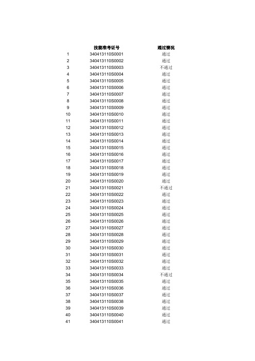
技能准考证号通过情况1 340413110S0001 通过2 340413110S0002 通过3 340413110S0003 不通过4 340413110S0004 通过5 340413110S0005 通过6 340413110S0006 通过7 340413110S0007 通过8 340413110S0008 通过9 340413110S0009 通过10 340413110S0010 通过11 340413110S0011 通过12 340413110S0012 通过13 340413110S0013 通过14 340413110S0014 通过15 340413110S0015 通过16 340413110S0016 通过17 340413110S0017 通过18 340413110S0018 通过19 340413110S0019 通过20 340413110S0020 通过21 340413110S0021 不通过22 340413110S0022 通过23 340413110S0023 通过24 340413110S0024 通过25 340413110S0025 通过26 340413110S0026 通过27 340413110S0027 通过28 340413110S0028 通过29 340413110S0029 通过30 340413110S0030 通过31 340413110S0031 通过32 340413110S0032 通过33 340413110S0033 通过34 340413110S0034 不通过35 340413110S0035 通过36 340413110S0036 通过37 340413110S0037 通过38 340413110S0038 通过39 340413110S0039 通过40 340413110S0040 通过41 340413110S0041 通过43 340413110S0043 通过44 340413110S0044 通过45 340413110S0045 通过46 340413110S0046 通过47 340413110S0047 通过48 340413110S0048 通过49 340413110S0049 通过50 340413110S0050 不通过51 340413110S0051 通过52 340413110S0052 通过53 340413110S0053 通过54 340413110S0054 通过55 340413110S0055 通过56 340413110S0056 通过57 340413110S0057 通过58 340413110S0058 通过59 340413110S0059 通过60 340413110S0060 通过61 340413110S0061 通过62 340413110S0062 通过63 340413110S0063 通过64 340413110S0064 通过65 340413110S0065 通过66 340413110S0066 通过67 340413110S0067 通过68 340413110S0068 通过69 340413110S0069 通过70 340413110S0070 通过71 340413110S0071 通过72 340413110S0072 通过73 340413110S0073 通过74 340413110S0074 通过75 340413110S0075 通过76 340413110S0076 通过77 340413110S0077 通过78 340413110S0078 通过79 340413110S0079 通过80 340413110S0080 通过81 340413110S0081 通过82 340413110S0082 通过83 340413110S0083 通过84 340413110S0084 不通过85 340413110S0085 通过87 340413110S0087 通过88 340413110S0088 通过89 340413110S0089 通过90 340413110S0090 通过91 340413110S0091 通过92 340413110S0092 通过93 340413110S0093 不通过94 340413110S0094 通过95 340413110S0095 通过96 340413110S0096 通过97 340413110S0097 通过98 340413110S0098 通过99 340413110S0099 通过100 340413110S0100 通过101 340413110S0101 通过102 340413110S0102 通过103 340413110S0103 通过104 340413110S0104 通过105 340413110S0105 通过106 340413110S0106 通过107 340413110S0107 通过108 340413110S0108 通过109 340413110S0109 通过110 340413110S0110 通过111 340413110S0111 通过112 340413110S0112 通过113 340413110S0113 通过114 340413110S0114 通过115 340413110S0115 通过116 340413110S0116 通过117 340413110S0117 通过118 340413110S0118 不通过119 340413110S0119 通过120 340413110S0120 通过121 340413110S0121 通过122 340413110S0122 通过123 340413110S0123 通过124 340413110S0124 通过125 340413110S0125 通过126 340413110S0126 通过127 340413110S0127 通过128 340413110S0128 通过129 340413110S0129 不通过131 340413110S0131 通过132 340413110S0132 通过133 340413110S0133 通过134 340413110S0134 通过135 340413110S0135 通过136 340413110S0136 通过137 340413110S0137 通过138 340413110S0138 不通过139 340413110S0139 通过140 340413110S0140 通过141 340413130S0001 通过142 340413130S0002 通过143 340413130S0003 通过144 340413130S0004 通过145 340413130S0005 不通过146 340413130S0006 通过147 340413130S0007 通过148 340413130S0008 通过149 340413130S0009 通过150 340413130S0010 不通过151 340413140S0001 通过152 340413140S0002 通过153 340413140S0003 不通过154 340413140S0004 通过155 340413140S0005 通过156 340413140S0006 通过157 340413140S0007 通过158 340413140S0008 通过159 340413140S0009 通过160 340413140S0010 通过161 340413140S0011 通过162 340413140S0012 不通过163 340413150S0001 通过164 340413150S0002 通过165 340413150S0003 通过166 340413150S0004 通过167 340413150S0005 通过168 340413150S0006 不通过169 340413150S0007 通过170 340413150S0008 通过171 340413150S0009 通过172 340413150S0010 通过173 340413150S0011 通过175 340413150S0013 通过176 340413210S0001 通过177 340413210S0002 通过178 340413210S0003 通过179 340413210S0004 通过180 340413210S0005 通过181 340413210S0006 不通过182 340413210S0007 通过183 340413210S0008 通过184 340413210S0009 通过185 340413210S0010 通过186 340413210S0011 通过187 340413210S0012 通过188 340413210S0013 不通过189 340413210S0014 通过190 340413210S0015 通过191 340413210S0016 通过192 340413210S0017 通过193 340413210S0018 通过194 340413210S0019 不通过195 340413210S0020 通过196 340413210S0021 不通过197 340413210S0022 通过198 340413210S0023 通过199 340413210S0024 不通过200 340413210S0025 通过201 340413210S0026 通过202 340413210S0027 不通过203 340413210S0028 通过204 340413210S0029 不通过205 340413210S0030 不通过206 340413210S0031 不通过207 340413210S0032 通过208 340413210S0033 通过209 340413210S0034 不通过210 340413210S0035 不通过211 340413210S0036 不通过212 340413210S0037 通过213 340413210S0038 通过214 340413210S0039 通过215 340413210S0040 通过216 340413210S0041 通过217 340413210S0042 通过219 340413210S0044 不通过220 340413210S0045 通过221 340413210S0046 通过222 340413210S0047 通过223 340413210S0048 通过224 340413210S0049 不通过225 340413210S0050 不通过226 340413210S0051 不通过227 340413215S0001 不通过228 340413215S0002 不通过229 340413215S0003 不通过230 340413240S0001 通过231 340413240S0002 通过232 340413240S0003 通过233 340413240S0004 通过234 340413240S0005 通过235 340413240S0006 不通过236 340413240S0007 通过237 340413240S0008 通过238 340413240S0009 通过239 340413240S0010 通过240 340413240S0011 通过241 340413240S0012 通过242 340413240S0013 通过243 340413240S0014 不通过244 340413240S0015 不通过245 340413240S0016 通过246 340413240S0017 不通过247 340413250S0001 不通过。
TPL0501 Datasheet SPI接口8位数字电位器
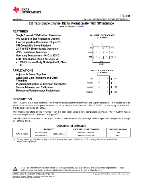
SCLKCSGNDDINHWVDDLWLCSHGNDVDDDINSCLKTPL0501 SLIS136A–SEPTEMBER2011–REVISED SEPTEMBER2011256Taps Single Channel Digital Potentiometer With SPI InterfaceCheck for Samples:TPL0501FEATURESMicroQFN–RSE PACKAGE•Single Channel,256-Position Resolution(TOP VIEW)•100kΩEnd-to-End Resistance Options•Low Temperature Coefficient:35ppm/°C•SPI-Compatible Serial Interface• 2.7V to5.5V Single-Supply Operation•±20%Resistance Tolerance•Operating Temperature–40°C to125°C•ESD Performance Tested per JESD22–2000V Human Body Model(A114-B,ClassII)SOT-23–DCN PACKAGE APPLICATIONS(TOP VIEW)•Adjustable Power Supplies•Adjustable Gain Amplifiers and OffsetTrimming•Precision Calibration of Set Point Thresholds•Sensor Trimming and Calibration•Mechanical Potentiometer ReplacementDESCRIPTIONThe TPL0501is a single channel,linear-taper digital potentiometer with256wiper positions.This device can be used as a three-terminal potentiometer or as a two-terminal rheostat.The TPL0501is currently offered with end-to-end resistance of100kΩ.The internal registers of the TPL0501can be accessed using a SPI-compatible interface.The TPL0501has a nominal temperature coefficient of35ppm/°C.The TPL0501is available in an8-pin SOT-23and8-microQFN package with a specified temperature range of–40°C to85°C.ORDERING INFORMATIONTA PACKAGE(1)ORDERABLE PART NUMBER TOP-SIDE MARKINGmicroQFN-RSE TPL0501-100RSER7M –40°C to125°C Tape and ReelSOT23–DCN TPL0501-100DCNR NF5T(1)Package drawings,standard packing quantities,thermal data,symbolization,and PCB design guidelines are available at/sc/package.Please be aware that an important notice concerning availability,standard warranty,and use in critical applications of TexasInstruments semiconductor products and disclaimers thereto appears at the end of this data sheet.PRODUCTION DATA information is current as of publication date.Copyright©2011,Texas Instruments Incorporated Products conform to specifications per the terms of the TexasWAGNDWWR WL =R TOT x D/256R HW =R TOT x (1–(D/256))VOLTAGE DIVIDER MODERHEOSTAT MODE ARHEOSTAT MODE BWhere D =Decimal Value of Wiper CodeWhere D =Decimal Value of Wiper CodeWhere D =Decimal Value of Wiper CodeWWORORV H V WL = (V H –V L )x D/256V HW = (V H –V L )x (1–(D/256))TPL0501SLIS136A –SEPTEMBER 2011–REVISED SEPTEMBER 2011These devices have limited built-in ESD protection.The leads should be shorted together or the device placed in conductive foam during storage or handling to prevent electrostatic damage to the MOS gates.FUNCTIONAL BLOCK DIAGRAMDIGITAL POTENTIOMETER CONFIGURATIONSFigure 1.DPOT Configurations2Submit Documentation FeedbackCopyright ©2011,Texas Instruments IncorporatedTPL0501 SLIS136A–SEPTEMBER2011–REVISED SEPTEMBER2011PIN FUNCTIONSPINNUMBER TYPE DESCRIPTIONNAMEDCN RSE16W I/O Wiper terminal27V DD Power Positive Supply Voltage34GND Ground Ground45SCLK Input SPI Clock52DIN Input SPI Input63CS Input SPI Chip Select.Active Low78L I/O Low terminal81H I/O High terminalABSOLUTE MAXIMUM RATINGS(1)(2)(3)over operating free-air temperature range(unless otherwise noted)MIN MAX UNIT V DD to GND Supply voltage range–0.37VV H,V L,V W–0.3V DD+0.3VI H Pulse current±20mAI LContinuous current TPL0501-100±5mAI WV I Digital input voltage range–0.37VRSE packagePackage thermalθJA°C/W impedance(4)DCN packageT stg Storage temperature range–65150°C (1)Stresses above these ratings may cause permanent damage.Exposure to absolute maximum conditions for extended periods maydegrade device reliability.These are stress ratings only,and functional operation of the device at these or any other conditions beyond those specified is not implied.(2)The algebraic convention,whereby the most negative value is a minimum and the most positive value is a maximum(3)All voltages are with respect to ground,unless otherwise specified.(4)The package thermal impedance is calculated in accordance with JESD51-7.ANALOG SPECIFICATIONSTypical Values are specified at VDD=5V and operating temperature of25CPARAMETER CONDITIONS MIN TYP MAX UNITEnd-to-end resistance(between HiR TOTAL80100120kΩand Li terminals)V H,V L Terminal voltage range0VDD VR H,R L Terminal resistance50150ΩH terminal floating,V L=GND,R W Wiper resistance25100ΩForce I W=(V DD/2)/R TOTAL,Input code=0x80hC H,C L Terminal capacitance15f=1MHz,measured to GND,Input code=0x80h pFC W Wiper capacitance12V H=GND to V DD,V L=Floating ORI LKG Terminal leakage current0.11uAV L=GND to V DD,V H=FloatingTC R Resistance temperature coefficient35ppm/°C VOLTAGE DIVIDER MODE(V H=V DD,V L=GND,V W=Not Loaded)INL Integral non-linearity–11LSB DNL Differential non-linearity–0.50.5LSB ZS ERROR Zero-scale error00.52LSB FS ERROR Full-scale error–2–0.50LSBCopyright©2011,Texas Instruments Incorporated Submit Documentation Feedback3TPL0501SLIS136A–SEPTEMBER2011–REVISED ANALOG SPECIFICATIONS(continued)Typical Values are specified at VDD=5V and operating temperature of25CPARAMETER CONDITIONS MIN TYP MAX UNITT CV Ratiometric temperature coefficient Wiper set at mid-scale4ppm/°C BW Bandwidth Wiper set at mid-scale,TPL0501-100,C LOAD=10pF265kHzT SW Wiper settling time TPL0501-1003µSV H=1V RMS at1kHz,THD Total harmonic distortion0.005%V L=V DD/2,measurement at WRHEOSTAT MODE(Measurements between Wi and Li with Hi not connected,or between Wi and Hi with Li not connected)RINL Integral non-linearity–11LSB RDNL Differential non-linearity–0.50.5LSBR OFFSET Offset00.52LSBCode=0x00h,L Floating,Input applied to W,10pFRBW Bandwidth60kHzon HOPERATING SPECIFICATIONSTypical Values are specified at VDD=5V and operating temperature of25CPARAMETER CONDITIONS MIN TYP MAX UNITI DD(STBY)V DD Standby current0.38µAI IN-DIG Digital pins leakage current(SCLK,DIN,CS inputs)–11µADigital Input=1.8V,VDD=2.7V5µAI DD(SUPPLV DD Supply CurrentY)Digital Input=1.8V,VDD=5V500µA SERIAL INTERFACE SPECS(SCLK,DIN,CS Inputs)V IH Input high voltage V DD=2.7V to5.5V 1.8 5.5VV IL Input low voltage SCLK,DIN,CS Inputs00.6VC IN Pin capacitance SCLK,DIN,CS Inputs710pF SPI INTERFACE TIMING CHARACTERISTICSf SCLK SCLK Frequency25MHzt SCP SCLK Period40nst SCH SCLK High time20nst SCL SCLK Low time20nst DS DIN to SCLK setup time5nst DH DIN hold after SCLK5nst CSS CS Fall to SCLK rise setup time15nst CSW CS Pulse width high40ns4Submit Documentation Feedback Copyright©2011,Texas Instruments IncorporatedTPL0501SLIS136A –SEPTEMBER 2011–REVISED SEPTEMBER 2011TYPICAL CHARACTERISTICSFigure 2.INL vs TAP POSITION (Potentiometer Mode)Figure 3.DNL vs TAP POSITION (Potentiometer Mode)Figure 4.INL vs TAP POSITION (Rheostat Mode)Figure 5.DNL vs.TAP POSITION (Rheostat Mode)Figure 6.End to End resistance change vs Temperature Figure 7.Zero Scale Error vs TemperatureCopyright ©2011,Texas Instruments Incorporated Submit Documentation Feedback5TPL0501SLIS136A –SEPTEMBER 2011–REVISED SEPTEMBER 2011TYPICAL CHARACTERISTICS (continued)Figure 8.Full scale Error vs TemperatureFigure 9.Temperature Coefficient vs Tap Position(Potentiometer Mode)Figure 10.Temperature Coefficient vs Tap PositionFigure 11.Bandwidth (potentiometer mode)(Rheostat Mode)6Submit Documentation FeedbackCopyright ©2011,Texas Instruments IncorporatedSCLKDIN 12345678 D7D6D5D4D3D2D1D0CS TPL0501 SLIS136A–SEPTEMBER2011–REVISED SEPTEMBER2011APPLICATION INFORMATIONSPI Digital InterfaceThe TPL0501uses a3-wire SPI compatible serial data interface.This write-only interface has three inputs: chip-select(CS),data clock(SCLK),and data input(DIN).Drive CS low to enable the serial interface and clock data synchronously into the shift register on each SCLK rising edge.After loading data into the shift register, drive CS high to latch the data into the appropriate potentiometer control register and disable the serial interface. Keep low during the entire serial data stream to avoid corruption of the data.Register Map:Bit76543210 MSB LSBD7D6D5D4D3D2D1D0SPI WRITE SEQUENCECopyright©2011,Texas Instruments Incorporated Submit Documentation Feedback7WR WL =R TOT x D/256R HW =R TOT x (1–(D/256))Where D =Decimal Value of Wiper CodeTPL0501SLIS136A –SEPTEMBER 2011–REVISED SEPTEMBER 2011IDEAL RESISTANCE VALUESBelow table shows the ideal values for DPOT with end-to End resistance of 10k Ω.The absolute values of resistance can vary significantly but the Ratio (Rhw/Rwl)is extremely accurate.10k ΩStep Binary R HW /R WL R HW (k Ω)R WL (k Ω)000.00100.000.00110.3999.610.002100.7899.220.01311 1.1798.830.014100 1.5698.440.025101 1.9598.050.026110 2.3497.660.027111 2.7397.270.0381000 3.1396.880.0391001 3.5296.480.04101010 3.9196.090.04111011 4.3095.700.04121100 4.6995.310.05131101 5.0894.920.05141110 5.4794.530.06151111 5.8694.140.061610000 6.2593.750.071710001 6.6493.360.0718100107.0392.970.0819100117.4292.580.0820101007.8192.190.0821101018.2091.800.0922101108.5991.410.0923101118.9891.020.1024110009.3890.630.1025110019.7790.230.11261101010.1689.840.11271101110.5589.450.12281110010.9489.060.12291110111.3388.670.133********.7288.280.133********.1187.890.143210000012.5087.500.148Submit Documentation FeedbackCopyright ©2011,Texas Instruments IncorporatedTPL0501 SLIS136A–SEPTEMBER2011–REVISED SEPTEMBER201110kΩStep Binary R HW/R WLR HW(kΩ)R WL(kΩ)3310000112.8987.110.153410001013.2886.720.153510001113.6786.330.163610010014.0685.940.163710010114.4585.550.173810011014.8485.160.173910011115.2384.770.184010100015.6384.380.194110100116.0283.980.194210101016.4183.590.204310101116.8083.200.204410110017.1982.810.214510110117.5882.420.214610111017.9782.030.224710111118.3681.640.224811000018.7581.250.234911000119.1480.860.245011001019.5380.470.245111001119.9280.080.255211010020.3179.690.255311010120.7079.300.265411011021.0978.910.275511011121.4878.520.275611100021.8878.130.285711100122.2777.730.295811101022.6677.340.295911101123.0576.950.306011110023.4476.560.316111110123.8376.170.316211111024.2275.780.326311111124.6175.390.3364100000025.0075.000.3365100000125.3974.610.3466100001025.7874.220.3567100001126.1773.830.3568100010026.5673.440.3669100010126.9573.050.3770100011027.3472.660.3871100011127.7372.270.3872100100028.1371.880.3973100100128.5271.480.4074100101028.9171.090.4175100101129.3070.700.4176100110029.6970.310.4277100110130.0869.920.4378100111030.4769.530.4479100111130.8669.140.4580101000031.2568.750.45Copyright©2011,Texas Instruments Incorporated Submit Documentation Feedback9TPL0501SLIS136A–SEPTEMBER2011–REVISED 10kΩStep Binary R HW/R WLR HW(kΩ)R WL(kΩ)81101000131.6468.360.4682101001032.0367.970.4783101001132.4267.580.4884101010032.8167.190.4985101010133.2066.800.5086101011033.5966.410.5187101011133.9866.020.5188101100034.3865.630.5289101100134.7765.230.5390101101035.1664.840.5491101101135.5564.450.5592101110035.9464.060.5693101110136.3363.670.5794101111036.7263.280.5895101111137.1162.890.5996110000037.5062.500.6097110000137.8962.110.6198110001038.2861.720.6299110001138.6761.330.63100110010039.0660.940.64101110010139.4560.550.65102110011039.8460.160.66103110011140.2359.770.67104110100040.6359.380.68105110100141.0258.980.70106110101041.4158.590.71107110101141.8058.200.72108110110042.1957.810.73109110110142.5857.420.74110110111042.9757.030.75111110111143.3656.640.77112111000043.7556.250.78113111000144.1455.860.79114111001044.5355.470.80115111001144.9255.080.82116111010045.3154.690.83117111010145.7054.300.84118111011046.0953.910.86119111011146.4853.520.87120111100046.8853.130.88121111100147.2752.730.90122111101047.6652.340.91123111101148.0551.950.92124111110048.4451.560.94125111110148.8351.170.95126111111049.2250.780.97127111111149.6150.390.981281000000050.0050.00 1.0010Submit Documentation Feedback Copyright©2011,Texas Instruments IncorporatedTPL0501 SLIS136A–SEPTEMBER2011–REVISED SEPTEMBER201110kΩStep Binary R HW/R WLR HW(kΩ)R WL(kΩ)1291000000150.3949.61 1.021301000001050.7849.22 1.031311000001151.1748.83 1.051321000010051.5648.44 1.061331000010151.9548.05 1.081341000011052.3447.66 1.101351000011152.7347.27 1.121361000100053.1346.88 1.131371000100153.5246.48 1.151381000101053.9146.09 1.171391000101154.3045.70 1.191401000110054.6945.31 1.211411000110155.0844.92 1.231421000111055.4744.53 1.251431000111155.8644.14 1.271441001000056.2543.75 1.291451001000156.6443.36 1.311461001001057.0342.97 1.331471001001157.4242.58 1.351481001010057.8142.19 1.371491001010158.2041.80 1.391501001011058.5941.41 1.421511001011158.9841.02 1.441521001100059.3840.63 1.461531001100159.7740.23 1.491541001101060.1639.84 1.511551001101160.5539.45 1.531561001110060.9439.06 1.561571001110161.3338.67 1.591581001111061.7238.28 1.611591001111162.1137.89 1.641601010000062.5037.50 1.671611010000162.8937.11 1.691621010001063.2836.72 1.721631010001163.6736.33 1.751641010010064.0635.94 1.781651010010164.4535.55 1.811661010011064.8435.16 1.841671010011165.2334.77 1.881681010100065.6334.38 1.911691010100166.0233.98 1.941701010101066.4133.59 1.981711010101166.8033.20 2.011721010110067.1932.81 2.051731010110167.5832.42 2.081741010111067.9732.03 2.121751010111168.3631.64 2.161761011000068.7531.25 2.20Copyright©2011,Texas Instruments Incorporated Submit Documentation Feedback11TPL0501SLIS136A–SEPTEMBER2011–REVISED 10kΩStep Binary R HW/R WLR HW(kΩ)R WL(kΩ)1771011000169.1430.86 2.241781011001069.5330.47 2.281791011001169.9230.08 2.321801011010070.3129.69 2.371811011010170.7029.30 2.411821011011071.0928.91 2.461831011011171.4828.52 2.511841011100071.8828.13 2.561851011100172.2727.73 2.611861011101072.6627.34 2.661871011101173.0526.95 2.711881011110073.4426.56 2.761891011110173.8326.17 2.821901011111074.2225.78 2.881911011111174.6125.39 2.941921100000075.0025.00 3.001931100000175.3924.61 3.061941100001075.7824.22 3.131951100001176.1723.83 3.201961100010076.5623.44 3.271971100010176.9523.05 3.341981100011077.3422.66 3.411991100011177.7322.27 3.492001100100078.1321.88 3.572011100100178.5221.48 3.652021100101078.9121.09 3.742031100101179.3020.70 3.832041100110079.6920.31 3.922051100110180.0819.92 4.022061100111080.4719.53 4.122071100111180.8619.14 4.222081101000081.2518.75 4.332091101000181.6418.36 4.452101101001082.0317.97 4.572111101001182.4217.58 4.692121101010082.8117.19 4.822131101010183.2016.80 4.952141101011083.5916.41 5.102151101011183.9816.02 5.242161101100084.3815.63 5.402171101100184.7715.23 5.562181101101085.1614.84 5.742191101101185.5514.45 5.922201101110085.9414.06 6.112211101110186.3313.67 6.312221101111086.7213.28 6.532231101111187.1112.89 6.762241110000087.5012.507.0012Submit Documentation Feedback Copyright©2011,Texas Instruments IncorporatedTPL0501 SLIS136A–SEPTEMBER2011–REVISED SEPTEMBER201110kΩStep Binary R HW/R WLR HW(kΩ)R WL(kΩ)2251110000187.8912.117.262261110001088.2811.727.532271110001188.6711.337.832281110010089.0610.948.142291110010189.4510.558.482301110011089.8410.168.852311110011190.239.779.242321110100090.639.389.672331110100191.028.9810.132341110101091.418.5910.642351110101191.808.2011.192361110110092.197.8111.802371110110192.587.4212.472381110111092.977.0313.222391110111193.36 6.6414.062401111000093.75 6.2515.002411111000194.14 5.8616.072421111001094.53 5.4717.292431111001194.92 5.0818.692441111010095.31 4.6920.332451111010195.70 4.3022.272461111011096.09 3.9124.602471111011196.48 3.5227.442481111100096.88 3.1331.002491111100197.27 2.7335.572501111101097.66 2.3441.672511111101198.05 1.9550.202521111110098.44 1.5663.002531111110198.83 1.1784.332541111111099.220.78127.002551111111199.610.39255.00Copyright©2011,Texas Instruments Incorporated Submit Documentation Feedback13PACKAGE OPTION ADDENDUM 26-Sep-2011Addendum-Page 1PACKAGING INFORMATION Orderable DeviceStatus (1)Package Type Package Drawing Pins Package Qty Eco Plan (2)Lead/Ball Finish MSL Peak Temp (3)Samples (Requires Login)TPL0501-100DCNRACTIVE SOT-23DCN 83000Green (RoHS & no Sb/Br)CU NIPDAU Level-1-260C-UNLIM TPL0501-100RSERACTIVE UQFN RSE 85000Green (RoHS & no Sb/Br)CU NIPDAU Level-1-260C-UNLIM (1) The marketing status values are defined as follows:ACTIVE: Product device recommended for new designs.LIFEBUY: TI has announced that the device will be discontinued, and a lifetime-buy period is in effect.NRND: Not recommended for new designs. Device is in production to support existing customers, but TI does not recommend using this part in a new design.PREVIEW: Device has been announced but is not in production. Samples may or may not be available.OBSOLETE: TI has discontinued the production of the device.(2) Eco Plan - The planned eco-friendly classification: Pb-Free (RoHS), Pb-Free (RoHS Exempt), or Green (RoHS & no Sb/Br) - please check /productcontent for the latest availability information and additional product content details.TBD: The Pb-Free/Green conversion plan has not been defined.Pb-Free (RoHS): TI's terms "Lead-Free" or "Pb-Free" mean semiconductor products that are compatible with the current RoHS requirements for all 6 substances, including the requirement that lead not exceed 0.1% by weight in homogeneous materials. Where designed to be soldered at high temperatures, TI Pb-Free products are suitable for use in specified lead-free processes.Pb-Free (RoHS Exempt): This component has a RoHS exemption for either 1) lead-based flip-chip solder bumps used between the die and package, or 2) lead-based die adhesive used between the die and leadframe. The component is otherwise considered Pb-Free (RoHS compatible) as defined above.Green (RoHS & no Sb/Br): TI defines "Green" to mean Pb-Free (RoHS compatible), and free of Bromine (Br) and Antimony (Sb) based flame retardants (Br or Sb do not exceed 0.1% by weight in homogeneous material)(3) MSL, Peak Temp. -- The Moisture Sensitivity Level rating according to the JEDEC industry standard classifications, and peak solder temperature.Important Information and Disclaimer:The information provided on this page represents TI's knowledge and belief as of the date that it is provided. TI bases its knowledge and belief on information provided by third parties, and makes no representation or warranty as to the accuracy of such information. Efforts are underway to better integrate information from third parties. TI has taken and continues to take reasonable steps to provide representative and accurate information but may not have conducted destructive testing or chemical analysis on incoming materials and chemicals.TI and TI suppliers consider certain information to be proprietary, and thus CAS numbers and other limited information may not be available for release.In no event shall TI's liability arising out of such information exceed the total purchase price of the TI part(s) at issue in this document sold by TI to Customer on an annual basis.IMPORTANT NOTICETexas Instruments Incorporated and its subsidiaries(TI)reserve the right to make corrections,modifications,enhancements,improvements, and other changes to its products and services at any time and to discontinue any product or service without notice.Customers should obtain the latest relevant information before placing orders and should verify that such information is current and complete.All products are sold subject to TI’s terms and conditions of sale supplied at the time of order acknowledgment.TI warrants performance of its hardware products to the specifications applicable at the time of sale in accordance with TI’s standard warranty.Testing and other quality control techniques are used to the extent TI deems necessary to support this warranty.Except where mandated by government requirements,testing of all parameters of each product is not necessarily performed.TI assumes no liability for applications assistance or customer product design.Customers are responsible for their products and applications using TI components.To minimize the risks associated with customer products and applications,customers should provide adequate design and operating safeguards.TI does not warrant or represent that any license,either express or implied,is granted under any TI patent right,copyright,mask work right, or other TI intellectual property right relating to any combination,machine,or process in which TI products or services are rmation published by TI regarding third-party products or services does not constitute a license from TI to use such products or services or a warranty or endorsement e of such information may require a license from a third party under the patents or other intellectual property of the third party,or a license from TI under the patents or other intellectual property of TI.Reproduction of TI information in TI data books or data sheets is permissible only if reproduction is without alteration and is accompanied by all associated warranties,conditions,limitations,and notices.Reproduction of this information with alteration is an unfair and deceptive business practice.TI is not responsible or liable for such altered rmation of third parties may be subject to additional restrictions.Resale of TI products or services with statements different from or beyond the parameters stated by TI for that product or service voids all express and any implied warranties for the associated TI product or service and is an unfair and deceptive business practice.TI is not responsible or liable for any such statements.TI products are not authorized for use in safety-critical applications(such as life support)where a failure of the TI product would reasonably be expected to cause severe personal injury or death,unless officers of the parties have executed an agreement specifically governing such use.Buyers represent that they have all necessary expertise in the safety and regulatory ramifications of their applications,and acknowledge and agree that they are solely responsible for all legal,regulatory and safety-related requirements concerning their products and any use of TI products in such safety-critical applications,notwithstanding any applications-related information or support that may be provided by TI.Further,Buyers must fully indemnify TI and its representatives against any damages arising out of the use of TI products in such safety-critical applications.TI products are neither designed nor intended for use in military/aerospace applications or environments unless the TI products are specifically designated by TI as military-grade or"enhanced plastic."Only products designated by TI as military-grade meet military specifications.Buyers acknowledge and agree that any such use of TI products which TI has not designated as military-grade is solely at the Buyer's risk,and that they are solely responsible for compliance with all legal and regulatory requirements in connection with such use. TI products are neither designed nor intended for use in automotive applications or environments unless the specific TI products are designated by TI as compliant with ISO/TS16949requirements.Buyers acknowledge and agree that,if they use any non-designated products in automotive applications,TI will not be responsible for any failure to meet such requirements.Following are URLs where you can obtain information on other Texas Instruments products and application solutions:Products ApplicationsAudio /audio Communications and Telecom /communicationsAmplifiers Computers and Peripherals /computersData Converters Consumer Electronics /consumer-appsDLP®Products Energy and Lighting /energyDSP Industrial /industrialClocks and Timers /clocks Medical /medicalInterface Security /securityLogic Space,Avionics and Defense /space-avionics-defense Power Mgmt Transportation and Automotive /automotiveMicrocontrollers Video and Imaging /videoRFID OMAP Mobile Processors /omapWireless Connectivity /wirelessconnectivityTI E2E Community Home Page Mailing Address:Texas Instruments,Post Office Box655303,Dallas,Texas75265Copyright©2011,Texas Instruments Incorporated。
8850-1eng 电导率表说明书
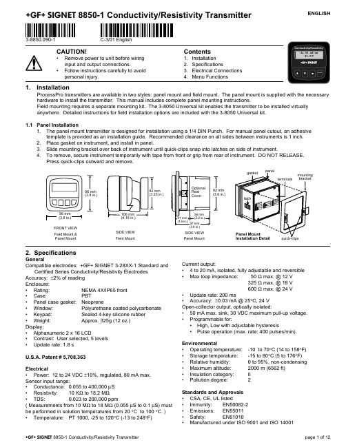
ENGLISH
3-8850.090-1
C-3/01 English
CAUTION!
• Remove power to unit before wiring input and output connections.
325 Ω max. @ 18 V 600 Ω max. @ 24 V • Update rate: 200 ms • Accuracy: ±0.03 mA @ 25°C, 24 V Open-collector output, optically isolated: • 50 mA max. sink, 30 VDC maximum pull-up voltage. • Programmable for: • High, Low with adjustable hysteresis • Pulse operation (max. rate: 400 pulses/min).
• Window:
Polyurethane coated polycarbonate
• Keypad:
Sealed 4-key silicone rubber
• Weight:
Approx. 325g (12 oz.)
Display:
• Alphanumeric 2 x 16 LCD
• Contrast: User selected, 5 levels
Environmental • Operating temperature: • Storage temperature: • Relative humidity: • Maximum altitude: • Insulation category: • Pollution degree:
苦马豆素研究进展 (1)
资料苦马豆素研究进展吴 达1,梁 冰2,冯志刚2,师彦平2(1.西北农林科技大学畜牧兽医学院,陕西杨凌 712100;2.中国科学院兰州化物所西北天然药物研究中心) 中图分类号:S853.7 文献标识码:B 文章编号:100026354(2003)022*******1 苦马豆素研究简史苦马豆素(s w ainsonine)因最初分离于灰苦马豆(Sw ain2 sona canesces)而得名〔1〕。
其发现历经一个世纪。
自从M arsh (1905~1907)〔2〕证实疯草病与采食某些棘豆属和黄芪属植物有关以后,许多学者进行了毒素的分离研究。
Cauch (1929)〔3〕从兰伯氏棘豆中分离出一种疯草毒素,可以引起猫的疯草病,他描述这种毒素是一种稳定的带有多羟基的含氮化合物,易溶于水,不溶于氯仿、乙醚和烃类溶剂,但由于当时条件所限未能进行结构鉴定。
F rap(1936)〔4〕从密柔毛黄芪中分离出一种毒性成分,呈碱性,吸水性强,取名为洛克因(L oco in),洛克因及其衍生物醋酸盐、酒石酸盐和柠檬酸盐都可以引起疯草中毒症状,但由于与一般生物碱试剂反应不明显,未能确定为生物碱。
苏联学者CePO b(1975)曾从短柔毛棘豆中用10%氨水提取总生物碱,并用TL C分离出三种生物碱,但也未作出结构鉴定。
由于灰苦马豆中毒与人类和动物的遗传性溶酶体贮积病——甘露糖过多症(m anno sido sis)的病理学及生物化学方面的变化相似,而甘露糖过多症是由于缺乏Α-甘露糖苷酶(Α-m anno sidase,AM A)引起的,澳大利亚学者Co legate (1979)〔1〕利用Α-甘露糖苷酶为工具从灰苦马豆中首次分离出一种纯毒素,并鉴定为吲哚兹定生物碱——苦马豆素(in2 do lizidine alkalo ids-s w ainonine)。
这是一个突破性的进展。
鉴于澳大利亚学者M aiden(1901)〔5〕发现澳大利亚绵羊灰苦马豆中毒的症状与美国绵羊疯草中毒非常相似,H artley (1978)〔6〕将灰盔叶苦马豆(s w ainsonia galgifo lia)同斑荚黄芪、A.ebentissi m u和绢毛棘豆进行了比较毒性试验,结果发现试验动物中毒后,不仅临床症状一致,而且病理组织学变化方面也没有明显差异,都表现出神经细胞和部分内脏细胞空泡化。
DAM0800-GPRS 产品说明书

DAM0800-GPRS继电器控制卡说明书V1.0北京聚英翱翔电子有限责任公司2016年01月目录一、产品说明 (1)二、产品特点 (1)三、产品功能 (1)四、产品选型 (1)五、主要参数 (1)六、通讯架构说明 (2)七、使用说明 (2)八、硬件说明 (3)1、接口说明 (3)2、继电器接线说明 (3)九、设备唯一ID号 (3)1、扫描二维码获取 (4)2、发送短信查询指令获取 (4)十、短信配置说明 (4)1、查询指令 (4)2、网络配置及查询 (5)3、软件生成指令 (6)十一、平台软件说明 (6)十二、软件下载 (7)1、网页版平台入口 (7)2、手机版软件下载 (7)十三、平台操作说明 (7)1、登陆 (7)2、添加设备 (8)3、实时监控 (10)4、删除设备 (14)十四、开发资料说明 (14)1、Modbus寄存器说明 (14)2、相关指令 (16)3、指令详解 (16)十五、技术支持联系方式 (18)一、产品说明DAM0800-GPRS设备是我公司DAM系列设备中GPRS版本的一种,设备基于移动和联通的GPRS网络来进行通讯,使用我司配套的云平台软件可实现远程控制设备功能,每个设备具有唯一ID号方便用户进行二次开发使用。
二、产品特点●供电电压DC7-30V;●继电器输出触点隔离;●使用GPRS通讯,SIM卡支持移动、联通,暂不支持电信;●通信波特率:2400,4800,9600,19200,38400●通信协议:支持标准modbus协议;三、产品功能●八路继电器控制;●可实现远距离操控;●具有闪开、闪断功能,可以在指令里边带参数、操作继电器开一段时间自动关闭。
四、产品选型型号modbus RS232RS485USB GSM继电器DAM0800-GPRS●●8五、主要参数参数说明触点容量10A/30VDC10A/250VAC耐久性10万次通讯接口GSM网络(移动、联通)额定电压DC7-30V电源指示1路红色LED指示(不通信时常亮,通信时闪烁)输出指示8路红色LED指示温度范围工业级,-40℃~85℃尺寸145*94*41mm重量330g默认通讯格式9600,n,8,1波特率2400,4800,9600,19200,38400软件支持配套配置软件、app控制软件,平台软件;支持各家组态软件;支持Labviewd等六、通讯架构说明设备使用基于移动或联通的GSM网络进行远程通讯,设备上插入移动或联通SIM卡即可,支持流量卡。
气象报文介绍
⽓象报⽂介绍常规⽓象报⽂内容介绍:1. 报头识别部分报头识别部分包括三项内容:1) 报告种类:a. METAR----例⾏观测:⽆论有⽆飞⾏任务,每⼩时观测⼀次,根据⽓象主管部门的要求,也可每半⼩时观测⼀次。
b. SPECI----特殊观测:指在两次例⾏观测之间的时段内,出现下列情况时所进⾏的观测:当能见度(跑道视程)、云、风达到或通过本场特选报规定的数值,或达到、通过本场运⾏最低标准时,某些要素达到或通过经空中交通管制部门或其他部门和⽓象部门商定的数值时。
2) 地名代码:ICAO 机场四字地名代码3) 观测时间观测的⽇期和时间,⽤⽇期/⼩时/分钟格式表⽰,加后缀Z表⽰世界协调时。
例如:METAR ZGGG 291020Z当⼀份天⽓通告包含⼀个或更多机场的天⽓报告时,编码METAR或SPECI由缩写SA或SP取代,后跟通告识别编码和观测⽇期及时间,各分项报告中不再出现编码METAR或SPECI和观测时间。
4) AUTO METAR在安装了能⾃动操作的⽓象观测台的机场,系统可能会以AUTO METAR 格式完全⾃动发布天⽓报告。
因为传感器⾃⾝的限制,有限的取样区域以及观测系统使⽤的不同单位,使⽤者需注意应谨慎对待⾃动系统提供的能见度,现时天⽓和云状的报告。
如果可能,AUTO METAR应使⽤其他的编码以指出观测系统的局限性。
2. 地⾯风1) 风向风速:⽓象风以真北为基准,以风的来向的最近的10度取整为单位(三位数字表⽰),后跟观测前10分钟的地⾯平均风向风速(两位数字,也有三位数字的例外)。
这些数据后不需要空格紧跟KT,KMH,MPS这三种缩写中的⼀种以强调⽤于报告风速的单位。
例如:31015KT2) 当最⼤风速超过平均风速10节或更多时,在风速后加G 和两位或三位数字指⽰最⼤阵风风速。
3) 静风⽤“00000”表⽰,其意义为两分钟或⼗分钟时距内的风速平均<>的风。
4) 风向不定⽤“VRB”表⽰,后跟风速和单位。
MCC 一系列高压电阻器数据表说明书
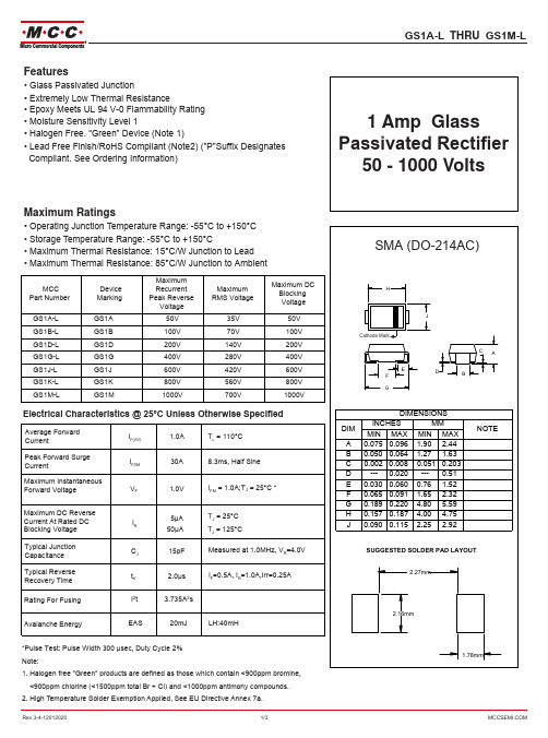
Features•Glass Passivated Junction•Extremely L ow T hermal R esistance•Epoxy Meets UL 94 V-0 Flammability Rating •Moisture Sensitivity Level 1•Halogen Free. “Green” Device (Note 1)•Lead Free Finish/RoHS Compliant (Note 2) ("P"Suffix Designates Compliant. See Ordering Information)Maximum Ratings•Operating Junction Temperature Range : -55°C to +150°C •Storage Temperature Range : -55°C to +150°C•Maximum Thermal Resistance : 15°C/W Junction t o L ead •Maximum Thermal Resistance : 85°C/W Junction t o A mbient1 Amp Glass Passivated Rectifier 50 - 1000 VoltsMCC Part Number Device Marking Maximum Recurrent Peak Reverse VoltageMaximum RMS VoltageMaximum DC Blocking VoltageGS1A-L GS1A 50V 35V 50V GS1B-L GS1B 100V 70V 100V GS1D-L GS1D 200V 140V 200V GS1G-L GS1G 400V 280V 400V GS1J-L GS1J 600V 420V 600V GS1K-L GS1K 800V 560V 800V GS1M-LGS1M1000V700V1000VElectrical Characteristics @ 25°C Unless Otherwise Specified*Pulse T est: Pulse W idth 300 µsec, Duty C ycle 2%Note:1.Halogen free "Green” products are defined as those which contain <900ppm bromine,<900ppm chlorine (<1500ppm total Br + Cl) and <1000ppm antimony compounds.2.High Temperature Solder Exemption Applied, S ee EU Directive Annex 7a .Average Forward CurrentI F(AV) 1.0A T L = 110°C Peak Forward Surge CurrentI FSM 30A8.3ms, H alf S ineMaximum Instantaneous Forward Voltage V F1.0VI FM = 1.0A;T J = 25°C *Maximum DC Reverse Current At Rated DC Blocking Voltage I R5μA 50μA T J = 25°C T J = 125°CTypical Junction Capacitance C J 15pF Measured at 1.0MHz, V R =4.0V Typical Reverse Recovery Time t rr 2.0µs I F =0.5A, I R =1.0A,Irr=0.25ARating F or Fusing I 2t 3.735A 2sAvalanche EnergyEAS20mJ LH:40mHCurve Characteristics0.010.1110100I n s t a n t a n e o u s R e v e r s e L e a k a g e C u r r e n t (μA )Fig. 2 - Typical Reverse Leakage Characteristics11005101520253035P e a k F o r w a r d S u r g e C u r r e n t (A )Percent of Rated Peak Reverse Voltage (%)Fig. 4 - Maximum Non-Repetitive Peak Forward SurgeCurrent10Number of Cycles at 60 Hz0.010.1110I n s t a n t a n e o u s F o r w a r d C u r r e n t (A )Fig. 1 - Typical Instantaneous Forward CharacteristicsInstantaneous Forward Voltage (V)020401201401600.00.20.40.60.81.01.21.4A v e r a g e F o r w a r d C u r r e n t (A )Fig. 3 - Forward Current Derating Curve6080100Lead Temperature (°C)Ordering InformationDevice PackingGS1A-LTP~GS1M-L TP Tape&Reel: 7.5Kpcs/Reel。
RJK0389DPA-00-J0资料
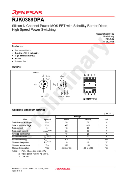
RJK0389DPASilicon N Channel Power MOS FET with Schottky Barrier Diode High Speed Power SwitchingREJ03G1722-010292. Value at Tch = 25°C, Rg ≥ 50 Ω3. Tc = 25°CElectrical Characteristics• MOS1(Ta = 25°C)Item Symbol Min Typ Max Unit Test ConditionsDrain to source breakdown voltage V (BR)DSS 30 — — V I D = 10 mA, V GS = 0 Gate to source leak current I GSS — — ±0.1 µA V GS = ±20 V, V DS = 0 Zero gate voltage drain current I DSS — — 1 µA V DS = 30 V, V GS = 0 Gate to source cutoff voltage V GS(off) 1.2 — 2.5 V V DS = 10 V, I D = 1 mAR DS(on) — 8.2 10.7 m Ω I D = 7.5 A, V GS = 10 V Note4 Static drain to source on stateresistance R DS(on) — 11.8 16.5 m Ω I D = 7.5 A, V GS = 4.5 V Note4 Forward transfer admittance |y fs | — TBD — S I D = 7.5 A, V DS = 10 V Note4 Input capacitance Ciss — 860 — pF Output capacitance Coss — 165 — pFReverse transfer capacitance Crss — 53 — pF V DS = 10 VV GS = 0 f = 1 MHz Gate Resistance Rg — 4.2 — Ω Total gate charge Qg — 6.3 — nC Gate to source charge Qgs — 2.3 — nC Gate to drain charge Qgd — 1.4 — nC V DD = 10 V V GS = 4.5 V I D = 15 A Turn-on delay timet d(on) — TBD — ns Rise timet r — TBD — nsTurn-off delay time t d(off) — TBD — nsFall timet f — TBD — nsV GS = 10 V, I D = 7.5 AV DD ≅ 10 V R L = 1.33 Ω R g = 4.7 Ω Body–drain diode forward voltage V DF — 0.84 1.10 V I F = 15 A, V GS = 0 Note4Body–drain diode reverse recovery time t rr — 20 — ns I F =15 A, V GS = 0di F / dt = 100 A/µsNotes: 4. Pulse test• MOS2(Ta = 25°C)Item Symbol Min Typ Max Unit Test ConditionsDrain to source breakdown voltage V (BR)DSS 30 — — V I D = 10 mA, V GS = 0 Gate to source leak current I GSS — — ±0.1 µA V GS = ±20 V, V DS = 0 Zero gate voltage drain current I DSS — — 1 mA V DS = 30 V, V GS = 0 Gate to source cutoff voltage V GS(off) 1.2 — 2.5 V V DS = 10 V, I D =1 mAR DS(on) — 6.8 8.9 m Ω I D = 10 A, V GS = 10 V Note4 Static drain to source on stateresistance R DS(on) — 10.5 14.7 m Ω I D = 10 A, V GS = 4.5 V Note4 Forward transfer admittance |y fs | — TBD — S I D = 10 A, V DS = 10 V Note4 Input capacitance Ciss — 1000 — pF Output capacitance Coss — 240 — pFReverse transfer capacitance Crss — 100 — pF V DS = 10 VV GS = 0 f = 1 MHz Gate Resistance Rg — 4.5 — ΩTotal gate chargeQg — 7.2 — nC Gate to source charge Qgs — 2.9 — nC Gate to drain charge Qgd— 2.2 —nC V DD = 10 V V GS = 4.5 V I D = 20 A Turn-on delay time t d(on) — TBD — ns Rise timet r — TBD — nsTurn-off delay timet d(off)— TBD —nsFall timet f — TBD — nsV GS = 10 V, I D = 10 AV DD ≅ 10 V R L = 1.0 Ω R g = 4.7 Ω Schottky Barrier diode forward voltage V F — 0.44 — V I F = 2 A, V GS = 0 Note4Body–drain diode reverse recovery time t rr — 12 — ns I F = 20 A, V GS = 0di F / dt = 100 A/µsNotes: 4. Pulse testPackage DimensionsRefer to "/en/network " for the latest and detailed information.Renesas Technology America, Inc.450 Holger Way, San Jose, CA 95134-1368, U.S.A Tel: <1> (408) 382-7500, Fax: <1> (408) 382-7501Renesas Technology Europe LimitedDukes Meadow, Millboard Road, Bourne End, Buckinghamshire, SL8 5FH, U.K.Tel: <44> (1628) 585-100, Fax: <44> (1628) 585-900Renesas Technology (Shanghai) Co., Ltd.Unit 204, 205, AZIACenter, No.1233 Lujiazui Ring Rd, Pudong District, Shanghai, China 200120Tel: <86> (21) 5877-1818, Fax: <86> (21) 6887-7858/7898Renesas Technology Hong Kong Ltd.7th Floor, North Tower, World Finance Centre, Harbour City, Canton Road, Tsimshatsui, Kowloon, Hong Kong Tel: <852> 2265-6688, Fax: <852> 2377-3473Renesas Technology Taiwan Co., Ltd.10th Floor, No.99, Fushing North Road, Taipei, Taiwan Tel: <886> (2) 2715-2888, Fax: <886> (2) 3518-3399Renesas Technology Singapore Pte. Ltd.1 Harbour Front Avenue, #06-10, Keppel Bay Tower, Singapore 098632 Tel: <65> 6213-0200, Fax: <65> 6278-8001Renesas Technology Korea Co., Ltd.Kukje Center Bldg. 18th Fl., 191, 2-ka, Hangang-ro, Yongsan-ku, Seoul 140-702, Korea Tel: <82> (2) 796-3115, Fax: <82> (2) 796-2145Renesas Technology Malaysia Sdn. BhdUnit 906, Block B, Menara Amcorp, Amcorp Trade Centre, No.18, Jln Persiaran Barat, 46050 Petaling Jaya, Selangor Darul Ehsan, Malaysia Tel: <603> 7955-9390, Fax: <603> 7955-9510RENESAS SALES OFFICES。
Micro800高速计数器功能性插件模块-RockwellAutomation

• S'assurer que l'environnement est classé non dangereux avant de changer les piles.
Les produits marqués "CL I, DIV 2, GP A, B, C, D" ne conviennent qu'à une utilisation en environnements de Classe I Division 2 Groupes A, B, C, D dangereux et non dangereux. Chaque produit est livré avec des marquages sur sa plaque d'identification qui indiquent le code de température pour les environnements dangereux. Lorsque plusieurs produits sont combinés dans un système, le code de température le plus défavorable (code de température le plus faible) peut être utilisé pour déterminer le code de température global du système. Les combinaisons d'équipements dans le système sont sujettes à inspection par les autorités locales qualifiées au moment de l'installation.
丹佛斯压缩机速查手册(32P)
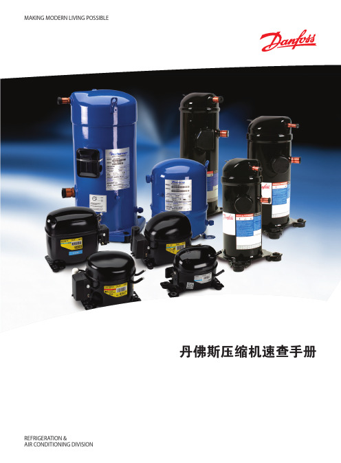
FR8.5GX 195B0026 103G6780
84.9 123 171 228 298 381 478 592 722
151 231 321
FR10GX
195B0024 103G6880
91.9 136 188 250 324 412 516 638 779
179 265 362
FR11GX
195B0028 103G6980
3
速查手册
活塞式压缩机 R134a
代码
EN 12900 (CECOMAF) 制冷量 [W]
EN 12900 (CECOMAF) 功率消耗 [W]
应用
HBP / MBP / (LBP)
压缩机
压缩机代码 压缩机 单个包装 代码
蒸发温度 [°C]
蒸发温度. [°C]
-35 -30 -25 -20 -15 -10 -5
推动技术变革 借助于不断的技术创新,丹佛斯通过提供高效、环保、低噪的产品来 为客户创造价值。
产品全,应用广 丹佛斯提供使用各种常见HFC、HCFC制冷剂的活塞压缩机和涡旋压 缩机。
涡旋压缩机 丹佛斯涡旋压缩机集高能效、超静音和高稳定性等优点于一身,冷量范围广,适用于轻商用到大型商用空调系统的R407C,R134a,R410A和R22的 单机和并联机一应俱全。
ptc启动启动继电器启动器盖子夹子垫片部分压缩机启动电容线夹电容运行电l2l1速查手册活塞式压缩机r404ar507压缩机制冷剂应用压缩机压缩机代码压缩机代码单个包装195b0021195b0031195b0038195b0350195b0151195b0379195b0399195b0332195b0070195b0427195b0439195b0443195b0345195b0323195b0391195b0392195b0436195b0437195b0438195b0166195b0032195b0075195b0077195b0089195b0111195b0112195b0113102u2071103u2670103u2890105f3710104l2533104l2623104l2853104l2123104l2322107b0500107b0501105f3720104l2506104l2606104l2869104l2139107b0502107b0503107b0504102u2038103u2680104l2525104l2625104l2856104l4091104l4092104l40934552779910258167226325406510812614614015127132549772135841451681991662372993954557039863011018922226325535345254261794912972514224329034036049061571581312401663201823073724304836507929181042158020925466698299681535192519631747160975994312171518en12900cecomaf制冷量1523038346853662583598811541306197425775266878381038121014191917239722938561180696412221612192810286473577657789104812081425160624273120645855103812851497177723652952281471775102812071550205524145352578796977129114581735119014301015tl4clxfr6clxfr85
