Fluke 36 Clamp Meter
Fluke 345电压质量电流计说明书
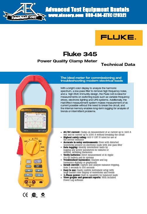
Technical Data• AC/DC current: Clamp-on measurement of ac current up to 1400 A rms and dc current up to 2000 A without breaking the circuit • Highest safety rating: 600 V CAT IV rated for use at the service entrance• Accurate in noisy environments: Even with distorted waveforms present on electronic loads with low-pass filter • Data logging: Identify intermittent faults by logging any power parameters for minutes or months, including harmonics• Verify batteries: Direct measurement of dc ripple (%) for battery and dc systems• Troubleshoot harmonics: Analyze and log harmonics digitally or graphically• Inrush current: Capture and analyze nuisance tripping, from 3 seconds to 300 seconds• Easy to use: Easily confirm instrument setup with large backlit color display of waveforms and trends • 3-Phase power: Built in capability for balanced loads •View graphs and generate reports: With included Power Log softwareFluke 345Power Quality Clamp MeterWith a bright color display to analyze the harmonicspectrum, a low-pass filter to remove high frequency noise, and a high EMC immunity design, the Fluke 345 is ideal for measurements on switching loads such as variable frequency drives, electronic lighting and UPS systems. Additionally, the Hall Effect measurement system makes measurement of dc current possible without the need to break the circuit, and the internal memory enables long-term logging for analysis of trends or intermittent problems.N1014019812 Fluke Corporation Fluke 345 Power Quality Clamp MeterLog measured parametersAll voltage, current, power, and harmonic measurements can be logged for minutes, hours, or months. Measurementaveraging periods from 1 second to 15 minutes can be selected depending on the application.Measured parameters can be logged into three separate recording memory areas. If longer recordings are required, the three areas may be combined into one. Stored measurements can be recalled and displayed on-screen in normal screen format or downloaded using the Power Log software package.ApplicationsSet up and troubleshoot variable frequency drives and UPS systems - Verify correct operation by measuring key parametersHarmonics measurements - Uncover harmonic issues that can damage or disrupt critical equipmentInrush capture - Check start-up current where spurious resets or nuisance circuit breaker tripping occurs Load studies - Verify electrical system capacity before adding loadsHarmonics measurements—view keyharmonic factors such as distortion factor and total harmonic distortion, as well as individual harmonics up to the 30thharmonic.Log parameters over time to track down intermittent faults.3 Fluke Corporation Fluke 345 Power Quality Clamp MeterFlexible and easy to useThe 345 measures a wide range of electrical parameters and can be used for many applications in today’s modern electrical environment. Measuring mode is selected by a simple turn of the rotary switch and the large color display presents data in a clear, easy-to-understand way.By default the display will show the most commonmeasurements, in very large format. If more detailed views are required they are available with the press of a single key (up to six measurements at once).Equipment performancemeasurement - power consumed by single- and three-phase balanced loads.View waveforms for equipment checking and setup.View recorded datain simple graphs and tables.Easily customizethe report.Create professional reports.Analysis and reporting softwareDesigned to quickly view recorded data, theincluded Power Log software displays all recorded parameters on interactive trends. Generate professional reports with the ‘Report Writer’ function, or copy and paste images into report document manually.• Easy-to-use tabbed window format allowsquick data evaluation.• One-step download and display capability • Waveform, harmonics, and trend download • Simple data export to other applicationsInrush currentDiagnose equipment start-ups with the inrush current mode. A current trigger level is set prior to recording. Once the level has been exceeded, the meter will begin capture. Recordings from 3 seconds to 300 seconds may be captured, and up to 1000 inrush events may be stored in the instruments memory.Screen captures and data loggingAny measurement can be stored in memory for later viewing, or downloaded to a PC. Simply press ‘SAVE’ to capture the active screen to memory – up to 50 screen shots can besaved for quick and simple documentation. Additionally, over 150,000 individual measurements can be logged for later review on the display or on a PC using Power Log software.Ambient conditions (For indoor use only)Reference conditions All accuracies stated at 23 °C ± 1 °C (73.4 °F ± 1.8 °F)Operating temperature0 °C to 50 °C (32 °F to 122 °F)Temperature coefficient of current≤ ± 0.15 % of rdg per °CTemperature coefficient of voltage≤ ± 0.15 % of rdg per °CMaximum relative humidity80 % for temperatures up to 31 °C (87 °F) decreasing linearly to 50 % relative humidity at40 °C (104 °F)Maximum operating altitude2000 mElectrical safetySafety IEC 61010-1 600 V CAT IV, double or reinforced insulation, pollution degree 2Protection IP40; EN60529Maximum safe working voltagesCurrent measurement 600 V ac rms or dc between uninsulated conductor and groundVoltage measurement600 V ac rms or dc between either input terminal and ground, or 825 V between energizedphase voltages (delta power config.)EMCEmission IEC/EN 61326-1:1997 class BImmunity IEC/EN 61326-1:1997MechanicalDimensions (length x width x depth)300 mm x 98 mm x 52 mm (12 in x 3.75 in x 2 in)Weight including batteries820 g/1.8 lbJaw opening60 mmJaw capacity58 mm diameterCleaning The unit can be cleaned with an Isopropanol impregnated cloth. Do not use abrasives orother solvents.4 Fluke Corporation Fluke 345 Power Quality Clamp Meter5 Fluke Corporation Fluke 345 Power Quality Clamp MeterVoltage measurement (dc, dc rms, ac rms)Measuring range0 to 825 V dc or ac rms Autorange facility 4 V/40 V/400 V/750 V Resolution 1 mV in 4 V range10 mV in 40 V range100 mV in 400 V range1 V in 750 V range AccuracyDC and dc rmsV > 1 V± 1 % rdg ± 5 digitsV < 1 V± 0.02 VAVGV > 1 V± 3 % rdg ± 5 digitsV < 1 V0.03 VPkV > 1 V± 5 % rdg ± 5 digitsV < 1 V± 0.03 VCF (Crest Factor)1.1 ≤ CF < 3± 3 % rdg ± 5 digits3 ≤ CF < 5± 5 % rdg ± 5 digitsResolution0.01RPL (Ripple)2 % ≤ RPL < 100 %±3 % rdg ± 5 digits100 % ≤ RPL < 600 %± 5 % rdg ± 5 digitsResolution0.1 %V dc> 0.5 V, V ac> 0.2 VAll measurements dc and 15 Hz to 1 kHzMaximum overload 1,000 V rmsVolts rms is a true-rms measurement (ac + dc)HarmonicsTHD (Total Harmonic Distortion)1 % ≤ THD < 100 %± 3 % rdg ± 5 digits100 % ≤ THD < 600 %± 5 % rdg ± 5 digitsResolution0.1 %DF (Distortion Factor)1 % ≤ DF < 100 %± 3 % rdg ± 5 digitsResolution0.1 %H02 ≤ V harm< H13± 5 % rdg ± 2 digitsH13 ≤ V harm ≤ H30± 10 % rdg ± 2 digits All measurements up to 30th harmonic (40th harmonic for 15 Hz to 22 Hz) Frequency range F0 15 Hz to 22 Hz and 45 Hz to 65 HzV acrms> 1V6 Fluke Corporation Fluke 345 Power Quality Clamp MeterPower factor (single- and three-phase)Power factorMeasuring range0.3 capacitive and 1.0 to 0.3 inductive (72.5° capacitive and 0° to 72.5° inductive) Resolution0.001Accuracy± 3°Frequency range15 Hz to 1 kHzDisplacement power factorMeasuring range0.3 capacitive and 1.0 to 0.3 inductive (72.5° capacitive and 0° to 72.5° inductive) Resolution0.001Accuracy± 3°Frequency range15 Hz to 22 Hz and 45 Hz to 65 Hz7 Fluke Corporation Fluke 345 Power Quality Clamp MeterMeasuring range40,000 kWHrAutorange facility 1 kWHr, 40 kWHr, 400 kWHr, 4,000 kWHr, 40,000 kWHr Resolution 1 WHr in 4 kWHr10 WHr in 40 kWHr100 WHr in 400 kWHr1 kWHr in 4,000 kWHr10 kWHr in 40,000 kWHrAccuracykWHr > 2 kWHr± 3 % ± 5 digitskWHr < 2 kWHr± 0.08 kWHrAll Watts /VA /VAR /PF measurementsFrequency range DC and 15 Hz to 1 kHzCurrent range10 A to 1400 A rmsVoltage range 1 V to 825 V rmsMaximum input825 V rms/1400 A rmsMaximum overload1000 V rms/10,000 AFrequency measurement(from current or voltage sources)Measuring range15 Hz to 1 kHzResolution0.1 HzAccuracy15 to 22 Hz ± 0.5 % rdg40 Hz to 70 Hz ± 0.5 % rdg15 Hz to 1000 Hz ± 1% rdgCurrent range10 A to 1400 A rmsVoltage range 1 V to 825 V rmsScope functionCurrent measurementRanges10 A/20 A/40 A/100 A/200 A/400 A/1000 A/2000 AResolution 1 A in 40 A10 A in 400 A50 A in 2000 AAccuracy± 3 % rdg ± 1 pixelMaximum overload 10,000 AVoltage measurementRanges 4 V/10 V/20 V/40 V/100 V/200 V/400 V/1000 VResolution100 mV in 4 V1 V in 40 V10 V in 400 V31.25 V in 1000 VAccuracy± 2 % rdg ± 1 pixelMaximum overload 1000 V rmsFrequency range DC and 15 Hz to 600 HzTime base 2.5 ms, 5 ms, 10 ms, 25 ms, 50 ms/divRefresh rate0.5 secondsMaximum sampling rate15.625 kHz8 Fluke Corporation Fluke 345 Power Quality Clamp MeterRanges40 A, 400 A, and 2000 AResolution10 mA in 40 A range100 mA in 400 A range1 A in 2000 A rangeAccuracyI > 10 A± 5 % rdg ± 1 pixelI < 10 A± 0.5 AAll measurements dc and 15 Hz to 1 kHzMaximum overload Maximum overload 10,000 A or rms x frequency < 400,000Amps rms is a true-rms measurement (ac + dc)Capture time 1 s, 3 s, 10 s, 30 s, 100 s, and 300 sMaximum sampling rate15.625 kHzInterfaceUSB Interface to a PCPower Log software for download, analysis, and reporting345 Upgrade Utility for installing a new firmware versionLogging MemoryLogging areas Three areas that can be used individually or combined into one large area Averaging periods 1 s, 2 s, 5 s, 10 s, 30 s, 1 min, 5 min, 10 min, 15 min, and custom9 Fluke Corporation Fluke 345 Power Quality Clamp MeterLogging timesVolts and current modeAverage time Logging time (1 area)Logging time (3 areas)1 s 1 h 49 m 5 h 12 m2 s3 h 38 m10 h 24 m5 s9 h 06 m 1 d 2 h 00 m10 s18 h 12 m 2 d 04 h 00 m30 s 2 d 06 h 36 m 6 d 12 h 01 m1 min 4 d 13 h 12 m13 d 00 h 03 m5 min22 d 18 h 00 m65 d 00 h 15 m10 min45 d 12 h 00 m130 d 00 h 30 m15 min68 d 06 h 00 m195 d 00 h 45 mV & A harmonics modeAverage time Logging time (1 area)Logging time (3 areas)1 s0 h 34 m 1 h 38 m2 s 1 h 08 m3 h 16 m5 s 2 h 52 m08 h 11 m10 s 5 h 44 m16 h 23 m30 s17 h 13 m 2 d 01 h 11 m1 min 1 d 10 h 26 m 4 d 02 h 23 m5 min7 d 04 h 10 m20 d 11 h 25 m10 min14 d 08 h 20 m81 d 0 h 50 m15 min21 d 12 h 30 m121 d 13 h 15 msingle- and three-phase power modeAverage Time Logging Time (1 area)Logging Time (3 areas)1 s 1 h 40 m 4 h 47 m2 s3 h 21 m9 h 34 m5 s8 h 22 m23 h 57 m10 s16 h 45 m 1 d 23 h 54 m30 s 2 d 02 h 17 m 5 d 23 h 42 m1 min 4 d 04 h 35 m11 d 23 h 25 m5 min20 d 22 h 55 m59 d 21 h 05 m10 min41 d 21 h 50 m119 d 18 h 10 m15 min62 d 20 h 45 m179 d 15 h 15 m10 Fluke Corporation Fluke 345 Power Quality Clamp Meter11 Fluke Corporation Fluke 345 Power Quality Clamp Meter Fluke Corporation PO Box 9090, Everett, WA USA 98206Fluke Europe B.V. PO Box 1186, 5602 BD Eindhoven, The NetherlandsFor more information call: In the U.S.A. (800) 443-5853 or Fax (425) 446-5116 In Europe/M-East/Africa +31 (0) 40 2675 200 or Fax +31 (0) 40 2675 222 In Canada (800) 36-FLUKE or Fax (905) 890-6866 From other countries +1 (425) 446-5500 or Fax +1 (425) 446-5116 Web access: ©2007 Fluke Corporation. All rights reserved. Specifications subject to change without notice. Printed in U.S.A. 1/2007 2643038 D-EN-N Rev C Fluke. Keeping your world up and running.™Ordering informationFluke-345Power Quality Clamp Meter Includes Soft carrying case Power Log software Test leads Alligator clips Test probes USB cable International ac adapter / battery eliminator Printed English language user manual Multi-language manual CDRecommended Accessories:TP220 SureGrip ™ Industrial Test Probes - One pair (red, black) of Industrial test probes. Sharp, 12 mm stainless steel tip provides reliable contact. Use with TL224 test leads.AC220 SureGrip ™ Alligator Clips - One pair (red, black) of small, insulated, nickel plated jaws. Blunt tip grabs round screwheads up to 9.5 mm. Use with TL224 test leads.TP1 Slim Reach Test Probes - One pair (red, black) of slender probe bodies for probing closely spaced or recessed terminals. Hard stainless steel probe tips with flat blade design to hold securely in blade type electrical wall sockets.L200 Probe Light - Small, rugged, and light the L200 easily attaches to any Fluke test probe. Bright white LED illuminates contact area and frees hands for work.L210 Probe Light and Probe Extenders - Includes L200 Probe Light and TP280 Test Probe Extenders to keep hands away from live circuits and light work area C550 Tool Bag - Steel reinforced frame with heavy duty hardware and large zippered storage compartment includes 25 pockets. Allows you to carry all your tools to the job site.TLK291 - Fused Test Leads provide extra safety with retractable sheath protectingcontact points.。
Fluke OS36-2 小型热敏电压传感器说明书

J-52The small size and built-in features of the OS36-2 make it ideal for infrared monitoring tasks. The narrow 35° field of view and small aperture allow small-target measurements of up to 4 mm (0.16"). The threaded head securely mounts through abulkhead or threads into a tapped hole. The internal air purge passages provide a convenient and highly efficient method of maintaining optical cleanliness in harsh environments.Compact Infrared ThermocoupleU I nfrared Thermocouple WorkhorseU 35° (2:1) Field of View U Built-In Air PurgeU J, K, E, or T Thermocouple Output Signal U Self-PoweredU Temperature CompensatedSpecificationsRange: -45 to 1150°C (-50 to 2000°F)See range chart for linear ranges. Measurement is practical beyondthermocouple table values by use of radiation laws. Polynomials available upon request.Field of View: 35° (2:1)Minimum Spot Size: 4 mm (0.16")Operating Ambient Temperature Range: -18 to 85°C (0 to 185°F)Air Purge: Built-in flow for operation at temperatures of -18 to 116°C (0 to 240°F)Ambient Temperature Compensation: Internal temperature cold junction compensation up to 538°C (1000°F) water-cooled, 400°C (750°F) air-cooled; cooling jacket optional (model OS36-SPC ) Output Impedance: 4 to 8 k Ω (varies by model)Dimensions: 6.22 L x 1.27 cm diameter (2.45 x 0.5"); 0.9 m (36") PFA coated lead wiresWeight: 44 g (1.6 oz) with cableComes complete with operator’s manual.Note: Stripped leads are standard.To order with GMPsubminiature low-noise thermocouple connector pair, add suffix “-GMP ” to model number for an additional cost.To order with GST standard-size low-noise thermocouple connector pair, add suffix “-GST ” to model number for an additional cost.Ordering Examples: OS36-2-K-140F-GMP, infraredthermocouple sensor Type K, with 25 to 80°C (80 to 180°F) range, GMP low-noise subminiature connectors.OS36-2-J-240F, infrared thermocouple sensor Type J, with 95 to 130°C (200 to 270°F) range.OCW-3, OMEGACARE SM extends standard 2-year warranty to a total of 5 years.OS36-2 SeriesOS36-2-J-140F shown actual size.**Right-Angle ModelsTo order with right-angle view, for use in difficult-to-view applications, change model number from “OS36-2” to “OS36-2-RA” for an additional cost.Ordering Example: OS36-2-RA-K-240F , infrared thermocouple, Type K, 95 to 130°C (200 to 270°F) range, right-angle view, stripped lead termination.Air Purge Standard.35° Field of Viewand Air Purge HeadOMEGACARE SM extendedwarranty program is available for models shown on this page. Ask your sales representative for full details when placing an order. OMEGACARE SM covers parts, labor and equivalent loaners.。
Fluke FEV100 电动汽车充电站适配器套件说明书

Fluke FEV100 Adapter Kit for Electric Vehicle Charging StationsVEHICLE SIMULATIONCP Control Pilot state simulation tests different charging statesGROUNDING PROTECTIONPE Pre-Test for dangerous voltageGFCI TESTINGStay protected from and check risk of electric shockCOMPATIBILITYIntegrates into Fluke portfolio of test and measurement toolsSAE J1772Complies with North American standardsTest the functionality and safety of electrical vehicle charging stations, easily and reliablyTest the safety and performance of type 1, level 1 or level 2 elec-tric vehicle ac charging stations (EVSEs) with the Fluke FEV100. This test adapter simulates the presence of an electrical vehicle, allowing you to conduct tests in combination with appropriate test instruments such as a digital multimeter or oscilloscope. Use the FEV100 to verify an EVSE is working properly after install and during periodic maintenance, or troubleshoot an EVSE if it is not delivering the appropriate charge.SafetyEVSE charging cables may become damaged over the course of use, increasing electric shock risks to users. Stay protected from and check risk of electric shock with the GFCI trip test. This function verifies the breaker of the EVSE is connected by detecting ground faults. Additionally, the PE grounding protection pre-test veri-fies that there is no presence of dangerous voltage at the ground terminal.Simplicity and conveniencePerform a variety of tests including ground fault checks, insula-tion of wires, measuring voltage and duty cycle to see max current available for charging all with one adapter that safely integrates with the Fluke portfolio of test and measurement tools. There is no need to bring an electric vehicle onsite for EVSE troubleshooting: the adapter acts as an electric vehicle when connected to an EVSE for easy performance and maintenance testing.How to test a charging stationOnce an EVSE recognizes it is connected to a “car” and is ready for charging, the adapter tests if the EVSE is performing the way it should be. 1. Perform the safety grounding protection pre-test to verify that no dangerous voltage is present in the grounding circuit. If the indica-tor lights up, it is possible that the electrical wiring has been set up improperly or there is a grounding malfunction. In this instance stop further testing immediately and check for a possible wiring fault of the ground conductor. 2. Verify station output voltage using an additional meter, such as the 87V digital multimeter.3. Verify station maximum preset charge current using CP terminals and a meter with a duty cycle function or an oscilloscope.4. Simulate the error states as described in the SAE J1772 standard: CP error “E”, GFCI trip test, and grounding error.CP error “E” simulationThe standard SAE J1772 defines Error “E” as a state when charging station is: disconnected from vehicle, disconnected from utility, there is a loss of utility power or control pilot is short to control pilot reference (ground). This error simulation tests the station to ensure that if there is an issue with the CP of the vehicle, the station and utility will not supply a charge to the vehicle.GFCIEach EVSE is required to be equipped with GFCI protection. On many stations, the GFCI protection is fully automatic and does not need a manual reset after the GFCI circuit is tripped.Ground Error (Ground Fault) simulationThe Ground Error button simulates an interruption of the ground conductor. As a result, the pending charging process is aborted and new charging processes are prevented.Advanced tests such as insulation resistance, power quality, analysis of the control pilot wave-form and loop impedance can also be done using the adapter in conjunction with appropriate test and measurement equipment.Verifying charging voltage with vehicle simulationThe CP state rotary switch selector simulates various vehicle states when the test adapter is connected to the charging station. Vehicle states are simulated with different resistances con-nected between CP and PE conductors.Ordering informationFluke FEV100 Adapter Kit for Electric Vehicle Charging StationsIncluded• Fluke FEV100/BASIC Test Adapter• Fluke FEV-CON/TY1 Type 1 Connector & Cable • Soft Carrying Case • User Manual • 3-year warrantyVisit to get complete details on these products or ask your local Fluke sales representative.The FEV100 is compatible with the Fluke portfolio of test and measurement tools. Take critical measurements such as voltage, waveform, loop impedance and resistance.Recommended tools for use with the FEV100• 87V Industrial Multimeter• 376 FC True-RMS Clamp Meter with iFlex • 1587 FC Insulation Multimeter• 1738 Three-Phase Power Quality Logger • 1630-2 FC Earth Ground Clamp • BT521 Advanced Battery Analyzer• 1664 FC Installation Multifunction Testers• 125B Industrial ScopeMeter® Handheld OscilloscopeFluke CorporationPO Box 9090, Everett, WA 98206 U.S.A.Fluke Europe B.V.PO Box 1186, 5602 BD Eindhoven, The NetherlandsFor more information call:In the U.S.A. (800) 443-5853 or Fax (425) 446-5116In Europe/M-East/Africa +31 (0) 40 2675 200 or Fax +31 (0) 40 2675 222In Canada (800)-36-FLUKE or Fax (905) 890-6866From other countries +1 (425) 446-5500 or Fax +1 (425) 446-5116Web access: ©2021 Fluke Corporation.Specifications subject to change without notice. Printed in U.S.A. 11/2021 211051-210646-en Modification of this document is not permitted without written permission from Fluke Corporation.Fluke. Keeping your world up and running.®。
Fluke 376便携式钳型表中文版手册

i
374, 375, 376
用户手册
ii
简介
XW 警告 使用仪表之前,请阅读“安全信息”。 Fluke 374、375 和 376(下称“仪表”)可以测量真有效值的交流电流和电压、直流电流 和电压、涌入电流、电阻以及电容。375 和 376 还可以测量频率和直流毫伏。可拆卸的 iFlex(灵活电流探头)随 376 一起提供(374 和 375 选配),可将量程扩展至 2500 A (交流)。 灵活电流探头提供更高的显示灵活性,允许测量各种尺寸的困难导体,并改善 了导线访问性。本手册中的图片显示的是 376。
W
B
) T ; ,
® -
7
374, 375, 376
用户手册
符号
含意 IEC 测量类别 III
符号
含意 IEC 测量类别 IV
CAT III
CAT III 设备可保护固定安装的设备 (例如大型建筑物中的配电盘、馈 电线和短支路电路以及照明系统) 免受瞬变带来的影响。
CAT IV
CAT IV 设备可保护设备免受主要电 源级别(例如电力计量仪表或者高空 线路或地下线路设施)瞬变带来的影 响。
或者,请访问 Fluke 公司网站:。 要注册您的产品,请访问 。 若要查看、打印或下载最新的手册附录,请访问 /usen/support/manuals。
2
Clamp Meters
安全信息
B F X
J ~ P
6
Clamp Meters
安全信息
符号
含意 有危险。重要信息。查看手册。 电池出现在显示屏上时表示电池电 量不足。 经 TÜV Product Services 检验及认 可。 不要应用到危险带电导线上或从中 取出。
771_福禄克
®771 Milliamp Process Clamp Meter说明书简介Fluke 771 毫安型过程钳型电表(简称“钳表”)是一种利用电池操作的手持式钳表,无需断开电路即可测量 4-20 mA dc(直流)。
与传统的钳表不同,本型钳表采用远端钳夹,通过延长电缆与钳表本体相连。
特性•使用通过延长电缆远端连接的钳夹进行 DC mA(直流毫安)测量(4-20 mA)•电子调零•百分比量程(0-100 %)•保持•显示屏背照灯•自动关机•测量 LED 指示聚光灯钳表配备有:•两节 AA 碱性电池(已安装)•软包•说明书PN 2567301September 2006 (Simplified Chinese)© 2006 Fluke Corporation. All rights reserved. Printed in China.All product names are trademarks of their respective companies.联系 Fluke要联系 Fluke,请拨打以下任何一个电话号码:美国:1-888-99-FLUKE (1-888-993-5853)加拿大:1-800-36-FLUKE (1-800-363-5853)欧洲:+31 402-675-200日本:+81-3-3434-0181新加坡:+65-738-5655世界各地: +1-425-446-5500或访问 Fluke 网站:。
钳表注册网址为:。
安全须知和符号“XW 警告”陈述表示可能会导致人身伤害或死亡的危险情况或行为。
“W 小心”陈述表示对钳表或被测设备可能造成损坏的情况或行为。
XW请先阅读:安全须知为了确保安全地操作和使用钳表,请遵守下列规定:•使用之前先阅读说明书,并遵守所有安全指示。
•必须按照说明书的规定使用钳表,否则钳表的安全装置可能会遭到损坏。
•每次使用之前,检验仪表和电缆是否存在损坏。
Fluke 902 HVAC Clamp Meter Users Manual

®PN 2547887 May 2006 Rev. 1, 3/07© 2006-2007 Fluke Corporation. All rights reserved. Printed in China.All product names are trademarks of their respective companies.902HVAC Clamp MeterUsers ManualLIMITED WARRANTY AND LIMITATION OF LIABILITY This Fluke product will be free from defects in material and workmanship for three years from the date of purchase. This warranty does not cover fuses, disposable batteries, or damage from accident, neglect, misuse, alteration, con-tamination, or abnormal conditions of operation or handling. Resellers are not authorized to extend any other warranty on Fluke’s behalf. To obtain service during the warranty period, contact your nearest Fluke authorized service cen-ter to obtain return authorization information, then send the product to that Service Center with a description of the problem.THIS WARRANTY IS YOUR ONLY REMEDY. NO OTHER WARRANTIES, SUCH AS FITNESS FOR A PARTICULAR PURPOSE, ARE EXPRESSED OR IMPLIED. FLUKE IS NOT LIABLE FOR ANY SPECIAL, INDIRECT, INCIDEN-TAL OR CONSEQUENTIAL DAMAGES OR LOSSES, ARISING FROM ANY CAUSE OR THEORY. Since some states or countries do not allow the exclusion or limitation of an implied warranty or of incidental or consequential dam-ages, this limitation of liability may not apply to you.Fluke CorporationP.O. Box 9090 Everett, WA 98206-9090 U.S.A. Fluke Europe B.V. P.O. Box 1186 5602 BD Eindhoven The Netherlands11/99Table of ContentsTitle Page Introduction (1)Contacting Fluke (2)Safety Information (3)Symbols (5)Getting Acquainted with the Meter (6)Using the Meter (10)AC and DC Voltage Measurement (10)Resistance and Continuity (11)Microamps µA Measurement (12)Temperature (13)Capacitance (16)AC Current Measurement (16)Backlight (18)MIN MAX Recording Mode (18)Display HOLD (19)Auto Off (19)Maintenance (20)Cleaning the Meter (20)Battery Replacement (21)Specifications (23)Electrical Specifications (23)General Specifications (24)902Users ManualList of TablesTable Title Page1. 902 HVAC Clamp Meter Features (7)2. Display Features (9)List of FiguresFigure Title Page1. 902 HVAC Clamp Meter Features (6)2. Display Features (8)3. Testing a Flame Rod (13)4. Temperature Measurement (15)5. Proper AC Current Measurement (17)6. Battery Replacement (22)902Users Manual902 IntroductionThe Fluke 902 is a hand-held battery-operated HVAC Clamp Meter (“the Meter”) that measures:•AC current•DC current (up to 200 µA for flame rod testing)•AC and DC voltages•Capacitance•Resistance•Continuity•Temperature in both Celsius (°C) and Fahrenheit (°F) The Meter comes with:•Two AA alkaline batteries (installed)•Users Manual•Soft carrying case•TL75 Test Leads (one pair)•80BK Integrated DMM Temperature Probe902Users ManualContacting FlukeTo contact Fluke, call one of the following telephone numbers:USA: 1-888-99-FLUKE (1-888-993-5853)Canada: 1-800-36-FLUKE (1-800-363-5853)Europe: +31 402-675-200Japan: +81-3-3434-0181Singapore: +65-738-5655Anywhere in the world: +1-425-446-5500Or visit Fluke’s Web site at: . Register the Meter at: HVAC Clamp MeterFlukeContacting Safety InformationA “XW Warning” statement defines hazardous conditions and actions that could cause bodily harm or death.A “W Caution” statement identifies conditions and actionsthat could damage the Meter or the equipment under test.XW Read First: Safety InformationTo ensure safe operation and service of theMeter, follow these instructions:•Read the Users Manual before use andfollow all safety instructions.•Use the Meter only as specified in theUsers Manual; otherwise, the Meter'ssafety features may be impaired.•Avoid working alone so assistance can berendered.•Never use the Meter on a circuit withvoltages higher than 600 V or a frequencyhigher than 400 Hz fundamental. The Metermay be damaged.•Never measure ac current while the testleads are inserted into the input jacks.•Do not use the Meter or test leads if theylook damaged.•Use extreme caution when working aroundbare conductors or bus bars. Contact withthe conductor could result in electricshock.902Users Manual•Use caution when working with voltages above 60 V dc or 30 V ac rms or 42 V acpeak. Such voltages pose a shock hazard.•Clean the case with a damp cloth and mild detergent only. Do not use abrasives orsolvents.•To avoid false readings that can lead to electrical shock and injury, replace thebatteries as soon as the low batteryindicator (B)appears. As the Meter getsto the point where the low batteries affectthe readings, the Meter locks and nomeasurements can be made until thebatteries are changed.•Do not hold the Meter anywhere beyond the tactile barrier, see Figure 1.•Adhere to local and national safety codes.Individual protective equipment must beused to prevent shock and arc blast injurywhere hazardous live conductors areexposed.HVAC Clamp MeterSymbolsSymbolsThe following symbols are found on the Meter or in this manual.,May be used on hazardous live conductorsW Risk of danger. Important information. See UsersManual.X Hazardous voltage. Risk of electric shock.T Double insulationB Battery)Complies with Canadian and US StandardsP Conforms to relevant European Union directivesJ Earth groundF DC (Direct Current)B AC (Alternating Current)~Do not dispose of this product as unsorted municipalwaste. Contact Fluke or a qualified recycler fordisposal.;Conforms to relevant Australian standardsN10140s Inspected and licensed by TÜV Product Services902Users ManualGetting Acquainted with the Meter Refer to Figures 1 and 2 and Tables 1 and 2 to become more acquainted with the Meter’s features.Figure 1. 902 HVAC Clamp Meter FeaturesHVAC Clamp MeterGetting Acquainted with the Meter Table 1. 902 HVAC Clamp Meter FeaturesNumber DescriptionA Backlight ButtonB Jaw ReleaseC Tactile BarrierD JawsE Hold ButtonF Rotary Switch:V DC and AC voltageP Resistance and continuityG DC microampsF Degrees Fahrenheit / degrees CelsiusL CapacitanceK AC currentG LCDH Min Max ButtonI AC/DC, °F/°C ButtonJ Input Terminals902Users ManualFigure 2. Display FeaturesHVAC Clamp MeterGetting Acquainted with the MeterTable 2. Display FeaturesNumber IndicationA Battery indicator -The batteries are low and need to be changed. XW Warning: To avoid false readings, which could lead to possible electric shock or personal injury, replace the batteries as soon as the battery indicator appears.B Indicates the presence of high voltageC Indicators for minimum and maximum recording modeD Display Hold is activeE VoltsF AmpsG °F - Degrees Fahrenheit °C - Degrees Celsius e - OhmsM - MicroampsN - MicrofaradsDC - Direct CurrentAC - Alternating Current902Users ManualUsing the MeterAC and DC Voltage MeasurementTo measure AC or DC voltage:1.Insert the test leads into the Meter.2.Turn the rotary switch to V.3.Press A to choose AC or DC voltage. The displayreflects the chosen voltage mode.e the test leads to take the measurement. The Meterreading appears on the display.NoteWhen a measured voltage is above 30 V,Z appears on the display. When the voltage dropsbelow 30 V, Z disappears.HVAC Clamp MeterUsing the MeterResistance and ContinuityTo measure resistance or continuity:XW WarningTo avoid false readings that can lead toelectrical shock and injury, de-energize thecircuit before taking the measurement.1.Insert the test leads into the Meter.2.Turn the rotary switch to P.3.Take the measurement. The resistance readingappears on the display.•If the resistance is shorted, the Meter beeps and shows a reading < 30 Ω.•If the resistance is open or exceeds the Meter’s range, the display reads OL.902Users ManualMicroamps µA MeasurementThe µA dc (G) function on the Meter is primarily for HVAC flame rod testing. To test a heating system flame rod (refer to Figure 3):1.Turn the heating unit off and locate the wire betweenthe gas-burner controller and the flame rod.2.Break this connection.3. Turn the rotary switch on the Meter to G.ing alligator clips, connect test leads between theflame sensor probe and control-module wire.5.Turn heating unit on and check the reading on theMeter.6.Refer to the heating unit documentation for what thedesired reading should be.HVAC Clamp MeterUsing the MeterFigure 3. Testing a Flame RodTemperatureThe Meter measures temperature in either Celsius (°C) or Fahrenheit (°F).To measure temperature (refer to Figure 4):902Users Manual1.Connect the 80BK Integrated DMM TemperatureProbe to the input jacks noting correct polarity of theprobe.2.Turn the rotary switch to F.3.Press A to select °C or °F. The display reflects thechosen temperature mode.4.Position the probe to take the measurement. Thereading appears on the display.NoteTo meet stated accuracy, the 80BK and Metermust be at the same temperature.XW WarningTo avoid possible electric shock DO NOT applythe probe tip to any conductor that is greaterthan 30 V ac, 42 V peak or 60 V dc to earth.Using the MeterFigure 4. Temperature MeasurementUsers ManualCapacitanceTurn off circuit power, then disconnect and discharge the capacitor before measuring capacitance. Turn the Meter’s rotary switch to capacitance (L).If the capacitor requires more discharging, diSC is displayed while the capacitor discharges. When measuring, be sure to note the correct polarity of the capacitor.AC Current MeasurementXW WarningTo avoid electrical shock and injury:•Remove Test Leads before making current measurements.•Do not hold the Meter anywhere beyondthe tactile barrier, see Figure 1.Turn the rotary switch to AC current (K). When measuring AC current, it is necessary that the measured wire be properly seated within the clamp jaws. The wire being measured should be centered within the jaws, below the horizontal line located on the clamp. Also note that currents moving in different directions will cancel each other out, so one wire must be measured at a time for a correct measurement (see Figure 5).Using the MeterFigure 5. Proper AC Current MeasurementUsers ManualBacklightPress C to toggle the backlight on and off. The backlight automatically turns off after 2 minutes.To disable the automatic 2-minute backlight timeout, hold down C while turning the Meter on.MIN MAX Recording ModeThe MIN MAX recording mode captures the minimum and maximum input values. When a new high or low is detected, the Meter beeps.To use this feature:1.Put the Meter into the desired measurement functionand range.2.Press J to enter MIN MAX Mode. MAX is displayedand the highest reading detected since entering MINMAX is displayed.3.Press J to step through the minimum (MIN) andpresent readings.4.To pause MIN MAX recording without erasing storedvalues, press I. K is displayed.5.To resume MIN MAX recording, press I again.6.To exit and erase stored readings, press J for atleast two seconds.Using the MeterDisplay HOLDXW WarningTo avoid possible electric shock or personalinjury, when Display HOLD is activated, beaware that the display will not change whenyou apply a different voltage.In the Display HOLD mode, the Meter freezes the display. The Meter also beeps every 4 seconds and H flashes to remind the user.Press I to activate Display HOLD; H is displayed and the reading is captured.To exit and return to normal operation, press I.Auto OffThe Meter automatically turns off after 20 minutes. The rotary switch must be turned to “OFF” and then turned back on for the Meter to restart. Auto Off is disabled during Min Max mode. To disable Auto Off, hold J when turning the Meter on.Users ManualMaintenanceXW WarningTo avoid possible electric shock or personalinjury, repairs or servicing not covered in thismanual should be performed only by qualifiedpersonnel.Cleaning the MeterXW WarningTo avoid electrical shock, remove any inputsignals before cleaning.W CautionTo avoid damaging the Meter, do not usearomatic hydrocarbons or chlorinated solvents for cleaning. These solutions will react with the plastics used in the Meter.Clean the instrument case with a damp cloth and mild detergent.MaintenanceBattery ReplacementXW WarningTo avoid false readings that could lead topossible electric shock or personal injury,replace the batteries as soon as the lowbattery indicator (B) appears.Disconnect the test leads before replacing thebatteries.To replace the batteries (refer to Figure 6):1.Turn the rotary switch to “OFF” and remove the testleads from the terminals.e a Phillips screwdriver to loosen the batterycompartment door screw, and remove the door fromthe case bottom.3.Remove the batteries.4.Replace the batteries with two new AA batteries.5.Reattach the battery compartment door to the casebottom and tighten the screw.Users ManualFigure 6. Battery ReplacementSpecifications SpecificationsElectrical SpecificationsFunction Range Resolution Accuracy Voltage DC 0 – 600 V 0.1 V 1 % ± 5 countsVoltage AC (True Rms) 0 – 600 V 0.1 V1 % ± 5 counts(50/60 Hz)Current AC (True Rms) 0 – 600 A 0.1 A2.0 % ± 5 counts(50/60 Hz)Current DC 0 - 200 µA 0.1µA 1.0 % ± 5 countsResistance 0 – 999 Ω0 – 9999 Ω0.1 Ω1.0 Ω1.5 % ± 5 countsContinuity <30ΩTemperature -10 to 400 °C 0.1 °C 1 % ± 0.8 °CCapacitance 1-100 µF100-1000 µF0.1 µF1 µF1.9 % ± 2 countsUsers ManualGeneral SpecificationsOperating Temperature -10 °C to +50 °CStorage Temperature -40 °C to +60 °COperating Humidity Non condensing (< 10 °C)90 % RH (10 °C to 30 °C)75 % RH (30 °C to 40 °C)45 % RH (40 °C to 50 °C)(Without Condensation) Operating Altitude 2500 meters above mean sealevelStorage Altitude 12,000 meters above meansea levelIP Rating IP 30 per IEC 60529 Vibration Requirements MIL-PRF-28800F Class 2random vibrationEMI, RFI, EMC EMI: instrument unspecified foruse in EMC field • 0.5 V /MeterEMC: Meets all applicablerequirements in EN61326-1Temperature Coefficients 0.1 x (specified accuracy)/ °C (<18 °C or >28 °C)HVAC Clamp Meter Specifications25Size (H X W X L) 9.1 x 3.8 x 1.7 inches (240 x 80 x 40 mm) Weight1.1 lb (310 g)Design Standards and Compliance IEC 61010, IEC 61010-2-032,CEAgency ApprovalsP ) ; sN10140Over-voltage Category600 V, CAT III per IEC 1010-1CAT III equipment is designed to protect against transients in equipment in fixed-equipment installations, such asdistribution panels, feeders and short branch circuits, and lighting systems in large buildings.Power Requirements Two AA Batteries , NEDA 15 A, IEC LR61.888.610.7664**************************Fluke -Direct .com902Users Manual26**************************1.888.610.7664。
雷尼绍探头工作原理

雷尼绍探头工作原理雷尼绍探头是一种常用于温度测量的装置,具有精度高、反应迅速等优点,广泛应用于工业生产、科研实验等领域。
本文将介绍雷尼绍探头的工作原理及其应用。
一、雷尼绍探头的结构雷尼绍探头主要由热电偶、保护管、接线盒等组成。
其中,热电偶是探头的核心部件,由两种不同材料的金属丝制成,分别为正极和负极。
保护管则用于保护热电偶不受外界环境的影响,同时还可以提高探头的机械强度和耐腐蚀性能。
接线盒则用于连接热电偶和检测仪器,保证信号的传输和接收。
二、雷尼绍探头的工作原理雷尼绍探头的工作原理基于热电效应,即在两种不同材料的金属丝连接处,如果两端温度不同,则会产生电动势。
这种电动势的大小与两种金属的热电势、温度差等因素有关,可以通过热电偶的特性曲线进行计算和测量。
具体来说,当雷尼绍探头的热电偶与被测体接触后,两端温度不同,就会产生微弱的电信号。
这个信号经过放大和处理后,可以转化为温度值,从而实现对被测体温度的测量。
三、雷尼绍探头的应用雷尼绍探头具有精度高、反应迅速等优点,广泛应用于工业生产、科研实验等领域。
常见的应用包括:1. 温度测量:雷尼绍探头可以测量各种物体的温度,包括液体、气体、固体等。
2. 控制系统:雷尼绍探头可以作为温度控制系统的传感器,实现对温度的自动调节和控制。
3. 热处理:雷尼绍探头可以用于热处理过程中的温度监测和控制,保证产品质量和生产效率。
4. 实验研究:雷尼绍探头可以用于各种实验研究中的温度测量和数据采集,为科学研究提供基础数据支持。
四、雷尼绍探头的注意事项在使用雷尼绍探头时,需要注意以下几点:1. 选择合适的保护管材料:不同的被测体环境可能对保护管材料产生不同的腐蚀和磨损,需要选择合适的保护管材料,保证探头的使用寿命和准确性。
2. 注意探头的安装位置:探头的安装位置应该尽可能接近被测体的中心位置,避免受到外界环境的影响,同时还需要考虑探头的安全性和便于维护。
3. 定期校准:由于热电偶的特性会随着时间和使用条件的变化而发生变化,需要定期对探头进行校准,保证测量的准确性和可靠性。
Fluke 365_用户手册中文版(便携式钳型表)
直流电流
量程 ......................................................... 200.0 A 分辨率 ..................................................... 0.1 A 准确度 ..................................................... 2% ± 5 位数
安全信息
警告表示会对用户产生危害的情况和操作;注意表示可能造成仪表损坏、待测试的设备损坏或数据 永久丢失的情况和过程。 有关仪表上和本手册中所用的符号,请参阅表 1 的解释。 2
Detachable Jaw True-rms Clamp Meter
安全信息
警告 为避免发生可能的触电或人身伤害,请遵守这些指导原则: • 只能按照本手册指定的方法使用仪表,否则仪表所提供的保护措施可能失效。 • 使用仪表之前先检查外壳。检查是否存在裂纹或缺少塑胶件。仔细检查接头附近的绝缘 情况。 • 切勿在测试表笔插入输入插孔时测量电流。 • 使用仪表之前,请确定电池盖已经闭合并且扣紧。 • 将测试表笔从仪表中拔下之后,才能打开电池盖。 • 检查测试表笔的绝缘是否损坏或导线金属是否裸露在外。检查测试表笔的连通性。请在 使用仪表之前更换已被损坏的测试表笔。 • 如果仪表无法正常操作,请勿使用。仪表的防护可能已经遭到破坏。若有疑问,应将仪 表送修。 • 请勿在爆炸性气体、蒸汽或在潮湿环境中使用仪表。 • 本仪表只使用 AA 型电池,请确定电池安装正确。 • 在测量时,应将手指放在触摸挡板后面的位置。参见“仪表”。 • 为避免因读数错误而导致触电或伤害,显示电量不足指示符 时应尽快更换电池。 • 在维修仪表时,请务必使用指定的备件。 • 请仅通过有资质的维修人员对仪表进行维修。 • 在以下电压值附近时请小心:> 30 V ac rms、42 V ac 峰值或 60 V dc。这些电压有导 致触电的危险。 3
Fluke 320 Series Clamp Meters产品说明书

FLUKE TOOLBELT KIT / FR FLUKE TOOLBELT KIT / UK FLUKE TOOLBELT KIT / VDEThe Fluke 323, 324 and 325 Clamp Meters are designed to perform in the toughest environments and provide noise-free, reliable results users can trust to confidently diagnose prob-lems. True-rms measurements and optimized ergonomics make the 320 Series Clamp Meters the best general troubleshooting tools for commercial and residential electricians.Technical Data Measurement capability •400 A ac current measurement (ac and dc current; 325 only)•600 V ac and dc voltagemeasurement•True-rms ac voltageand current for accuratemeasurements on non-linearsignals•Resistance measurement toup to 40 kΩ with continuitydetection•Temperature and capacitancemeasurement (324 and 325only)•Frequency measurement(325 only)Features•Slim, ergonomic design•Large, easy to read backlightdisplay (324 and 325 only)•CAT IV 300 V/CAT III 600 Vsafety rating•Hold button•Two-year warranty•Soft carrying caseFluke rugged. Fluke precise. Fluke reliable.320 Series True-rmsClamp Meters300V600VFluke CorporationPO Box 9090, Everett, WA 98206 U.S.A.Fluke Europe B.V.PO Box 1186, 5602 BD Eindhoven, The NetherlandsFor more information call:In the U.S.A. (800) 443-5853 or Fax (425) 446-5116In Europe/M-East/Africa +31 (0) 40 2675 200 or Fax +31 (0) 40 2675 222In Canada (800)-36-FLUKE or Fax (905) 890-6866From other countries +1 (425) 446-5500 or Fax +1 (425) 446-5116Web access: ©2012 Fluke Corporation.Specifications subject to change without notice. Printed in U.S.A. 5/2012 4217271A_ENModification of this document is not permitted without written permission from Fluke Corporation.Fluke. Keeping your world up and running.®Ordering information323 True-rms Clamp Meter324 True-rms Clamp Meter 325 True-rms Clamp MeterIncluded with all modelsClamp meter, test leads, soft case, and users manual.SpecificationsT90/T110/T130/T150Voltage and Continuity TestersTechnical DataListening to customers. Making better tools.The new Fluke two-pole voltage and continuity testers are now more rugged and easier to use than ever before.• Fast test results the wayyou need them, with large, easy-to-use buttons, bright backlights, and clear audible and physical indicators designed for any work situation.• Rugged, high-quality con-struction is built to last. This includes a heavy duty molded case, a thicker cord with wear indicator, sturdy battery case, and well-fitting and durable probe protector.• Enhanced ergonomic design feels good in your hand, is easy to use (even with gloves) and quick, secure probe docking.• A complete family of testers with the features, functions, and price/performance to fit your applications and preferences.test results the way you need themAll electricians need a two-pole tester. Experienced professionals know that they can—and should—trust their job, their reputation and even their personal safety to Fluke electrical test tools. Our new family of two-pole voltage and continuity testers is no exception. Built with state-of-the-art measurement and safety technology, these testers offer everything you expect from Fluke, and a little bit more.Fluke’s new two-pole testers are built with youin mind. They give you the best combination of safety, ease-of-use and fast answers available anywhere.•CAT IV 600 V, CAT III 690 V safety rating. Fluke’s new family of two-pole testers comply with both regulation HSE GS 38 (tip caps) and IEC EN 61243-3: 2010, the most recent and applicable standards for this type of test equipment.•4 ways to detectac/dc voltage.Fluke two-poletesters makeanswers easyto understand,indicating voltagefour ways: A clear,instantly visibleLED indicator,a bright digitaldisplay of the mea-surement value, anaudible continuitytest, and vibrationto give tactile feedback (vibration indicator on T110, T130, T150). It’s your preference. Use the most effective method for each situation.•Backlit graduated scale and backlit indica-tors. Bright backlights ensure that the buttons and the indicators are visible under any lighting conditions—and you can easily see and under-stand the answers.•Vibration provides tactile feedback (T110,T130, T150). Even when viewing the display or hearing the beeper is difficult, you’ll know voltage is present. This is especially useful in noisy environments, or when you can’t take your eyes off the probes.•Audio on/off for testing in quiet areas.If you’re working in quiet surroundings, such as a medical or office setting, you don’t want to disturb people in the vicinity with noises. The tester’s acoustic alert switches on or off to fit your environment.• Never guess whether your batteries are in good working order. The low battery indica-tor gives you advance warning when they fall below proper working voltage. •Detects voltage even with discharged batteries. The tester can still detect the pres-ence of voltage (>50 V ac, >120 V dc) even with dead batteries, an important safety feature. You should always use your two-pole tester with working batteries, but for that rare time when your batteries fail in the field, it’s nice to know you still have this one indication of live voltage.•Improved probe docking for secure stor-age.When the probes are docked, the two-pole tester is ready to use, with proper spacing for instant testing on standard outlets. If you’ve ever been frustrated with wobbly probes that slowed you down, you’ll appreciate Fluke’s rugged design.•Phase rotation indicator for 3-phase systems. Where three-phase power supplies feed motors, drives and electrical systems, use Fluke’s innovative three-phase rotation detection system to quickly determine phase sequence. Ensure the system is wired correctly, without reaching for another tool.•RCD functionality. Convenient two-button controls allow you to draw more current from the circuit under test and intentionally trip Residual-Current Devices (RCDs) remotely and determine if they are wired correctly. A Quick Start Guide covering the basics of RCD testing is included with the product.•Display hold (T130, T150). Focus on placing your probes, take the measurement, then read the LC display.•Built in electric torch (T110, T130, T150). Light up dim testing environments at the touchof a button for faster, safer probing.•Single-phase voltage offers fast identifica-tion of live conductors. Need to verify that a row of “hot” conductors are indeed connected to power? The two-pole tester can tell with you a single touch of the main probe. Simply touch a live conductor and the probe instantly give an audible and visual signal if the power is on. A great timesaver before you begin actual testing.• Probe tip protection adapts to your changing environment. Push-on probe tips reduce metal exposure from 19 mm to 4 mm, reducing the chance ofaccidentallytouching thewrong conductorwhen probing intight spaces. Theprobe tips of thetwo-pole testerare threaded,taking optionalscrew-on 4 mmdiameter tipsfor applicationswhere moresturdy probingmay be required.•Probe tip protector and storage accessory. Never lose the push-on caps and 4 mm diameter tips again. As a bonus, the tool’s storage serves as an extra hand when opening UK electrical safety outlets.•Resistance testing (T150). Testers measure and display resistance up to 1999 ohms, adding more power and versatility to this essential tester.•WearGuard™ insulation shows damage to test leads. The two-pole tester’s rugged, durable test leads have two layers of insulation for added durability. But if the inner, contrasting-colored layer is showing, that’s a sign that the test leads have been damaged and replacement is in order.Selection tableOrdering informationFLUKE-T90 Voltage/Continuity TesterFLUKE-T110 Voltage/Continuity Tester With Switchable LoadFLUKE-T130 Voltage/Continuity Tester With LCD, Switchable LoadFLUKE-T150Voltage/Continuity Tester With LCD, Ohms, Switchable LoadFluke Europe B.V.P .O. Box 11865602 BD Eindhoven The NetherlandsWeb: For more information call:In Europe/M-East/Africa +31 (0)40 2 675 200or Fax +31 (0)40 2 675 222Fluke (UK) Ltd.52 Hurricane Way Norwich, Norfolk NR6 6JBUnited KingdomTel.: +44 (0)20 7942 0700Fax: +44 (0)20 7942 0701E-mail:*******************.nl Web: ©2011 Fluke Corporation.Specifications subject to change without notice. Printed in U.S.A. 11/2011 4115552A D-EE Pub_ID: 11842-engModification of this document is not permitted without written permission from Fluke Corporation.Fluke. Keeping your world up and running.®SpecificationsGeneral specificationsPower requirement 2-AAA batteries Net weight 180 g (6.4 oz) (T90)280 g (9.9 oz) (T110. T130, T150)Size (LxWxH)23 cm x 6.5 cm x 3.8 cm (T90)26 cm x 7 cm x 3.8 cm (T110. T130, T150)Warranty2 years Country of originRomaniaFluke 1AC IILVD1LVD2SM100SM200SM300FLUKE TOOLBELT KIT / FR FLUKE TOOLBELT KIT / UK FLUKE TOOLBELT KIT / VDE。
Fluke 312, 316, 318 Clamp Meter 用户手册说明书

PN 1989445July 2002 Rev. 2, 2/06© 2002, 2006 Fluke Corporation, All rights reserved. Printed in China. All product names are trademarks of their respective companies.312, 316, 318Clamp Meter用户手册®有限保证和有限责任本款Fluke公司的产品保证没有材料和工艺上的缺陷,保证期从购买之日起为一年。
此项保证不包括保险丝、普通电池,也不包括由于意外情况、疏于管理、错误使用、经过改动、受到污染或不正常的操作或搬运条件所引起的损坏。
代理商无权以Fluke的名义扩大任何其它的保证条款。
欲在保证期内获得维修服务,请将本产品退回购货点并附以故障情况说明。
这种保证是您唯一的补救方法。
任何其它的保证条款(如为某种特定目的的适应性)均未表述或默许。
FLUKE对于任何特别的、间接的、意外的或后果性的,由于任何原因或理论引起的损坏或丢失都不承担责任。
由于某些州或者国家不允许排斥或者限制默认保证条款或者意外的或后果性的损坏,此项有限责任可能不适用于您。
Fluke CorporationP.O. Box 9090Everett, WA 98206-9090U.S.A.维修站地址:美国福禄克公司北京办事处北京建国门外大街22号赛特大厦2301室电话:010-65123435上海世禄仪器有限公司上海市虹梅南路2638弄139号邮编:201108标准号:Q/SXAV 2-2002目录标题页数安全信息 – 首先阅读 (1)一般技术指标 (4)电气性能技术指标 (5)仪器概述 功能位置 (6)符号定义 (7)进行测量 (7)测量 AC 电流 (8)测量 DC 电流 (仅限316, 318) (9)测量 AC 和 DC 电压 (9)测量电阻 (12)测量通断性 (13)二极管测试 (14)数据保持 (15)峰值 (15)MIN MAX (仅限316, 318) (15)REL (S) (仅限316, 318) (16)量程 (仅限312) (16)更换电池 (16)仪表的清洁工作 (16)维护 (16)iii312, 316, 318安全信息 – 首先阅读W警告: 使用前首先阅读为了避免可能发生的电击或人身伤害:•只能按照本手册的规定来使用此仪表,否则仪表提供的保护能力可能受到损害。
Fluke 772和773毫安特征闸簇测量仪用途说明书

Technical DataFluke 772 and 773 Milliamp ProcessClamp MetersUse the Fluke 772 and 773 to:• Measure 4 to 20 mA signals without ”breaking theloop” just like the innovative and popular Fluke 771 Process Milliamp Clampmeter• Source 4 to 20 mA signals for testing control system I/O or I/Ps• Simulate 4 to 20 mA signals for testing control system I/O• Measure 4 to 20 mA signals with in-circuit measurement• Simultaneously measure mA in-circuit with 24 V loop power for powering and testing transmitters • Source mA output signals in a linear ramp or 25 % step output– Automatically change the 4 to 20 mA output for remote testing• Power saving features, auto-off, backlight timeout extend battery lifeFluke 773 features:• DC voltage measurement to verify 24 V powersupplies or voltage I/O signals• Source dc voltage to test input devices that accept a 1 to 5 volt or 0 to 10 volt signal• Scaled mA output provides a continuous mA signal that corresponds to the 4 to 20 mA signal measured by the mA clamp– Output mA signal enables a logging DMM (289)or other device to record the 4 to 20 mA signal without breaking the loop• mA in/out: simultaneously measure the mA signal with the clamp and source a mA signal– Apply a mA input signal to a device and measure its’ 4 to 20 mA output on devices such as valves or mA isolators• Voltage output linear ramp or 25 % step output – Automatically change the voltage output for remote testing1981(see /771 for more information on the Fluke 771 specifications) Ordering informationFluke-772Milliamp Process Clamp MeterFluke-773Milliamp Process Clamp MeterIncluded accessoriesSoft carrying case, test leads, alligator clips, hangingstrap and user’s manual.772773Fluke CorporationPO Box 9090, Everett, WA 98206 U.S.A.Fluke Europe B.V.PO Box 1186, 5602 BDEindhoven, The NetherlandsFor more information call:In the U.S.A. (800) 443-5853 orFax (425) 446-5116In Europe/M-East/Africa +31 (0) 40 2675 200 or Fax +31 (0) 40 2675 222In Canada (800)-36-FLUKE orFax (905) 890-6866From other countries +1 (425) 446-5500 or Fax +1 (425) 446-5116Web access: ©2009 Fluke Corporation. Specifications subject to change without notice. Printed in U.S.A.5/2009 3442293 D-EN-N Rev BModification of this document is not permitted without written permission from Fluke Corporation. Fluke. Keeping your worldup and running.®2 Fluke Corporation 772 and 773 Milliamp Process Clamp Meters。
罗斯蒙特涡街流量计说明书

The transducer block calculates flow from sensor frequency. The calculation includes information about damping, shedding frequency, K-factor, service type, pipe ID, and diagnostics.
• Replaceable Sensor - The sensor is isolated from the process and can be replaced without breaking the process seals. All line sizes use the same sensor design allowing a single spare to serve every meter.
• Alignment rings, provided with each wafer-style flowmeter, ensure that the meter body is properly centered with the adjacent piping.
• Both wafer and flanged style meter bodies are available in 316L stainless steel and Nickel Alloy materials of construction.
• Available as flanged meter for 1 through 12 inch stainless steel and nickel alloy C materials of construction.
飞库1630地球电压测试器说明书

Technical DataFluke 1630 Earth Ground Clamp Meter • A wide ground loop resistance range, from 0.025 Ω to1500 Ω, to satisfy all requirements• Large jaw opening of 35 mm (1.38 in) for tests on ground conductors and/or equipotential bus bars• Measurement of ground leakage current, from 0.2 mA to 1000 mA, without needing to disconnect - ideal for system troubleshooting • Wide ac current measurement range from 0.2 A to 30 A allows one instrument for multiple applications• Continuity loop test - quickly assess whether resistance is less than 40 Ω, with audible alarm• User-defined HI / LO Alarm limits, for rapid measurement evaluation • Handy “Display-Hold” button for capturing readings in hard-to-reach places• Time saving memory function automatically records and stores measured values • Automatic self calibration ensures correct measurement every time The clamp-on ground testing technique used by the Fluke 1630 simplifies ground loop testing and enables non-intrusive leakage current measurement. The compact and rugged design makes the Fluke 1630 easy to use in small places and harsh environ-ments, while the “Display-Hold” and the continuity test-ing with an audible alarm function, ensures convenience in use. The novel technique means that earth ground loop testing and continuity testing can be completed without breaking the circuit.1981Stakeless testing systemThe Fluke 1630 uses the Stakeless testing method, which eliminates the need to disconnect parallel ground rods and find suitable locations for placing auxiliary ground stakes. This saves time and enables users such as industrial and utility electricians, and field service electricians and contractors, to perform earth ground loop tests in locations where it is not possible to use other techniques, such as inside buildings or on power pylons. With the Stakeless testing method, earth ground stakes are no longer necessary. The Fluke 1630 Earth Ground Clamp is placed around the earth ground rod or the connecting cable. A known voltage is induced by one half of the clamp and the current is measured by the other half. The tester automatically determines the ground loop resistance at this grounding connection. Applications• Earth Ground loop testing in various installations - for example, high voltage pylons, buildings, cell phone substations, RF transmitters, etc.• Inspection of lightning protection systems• Leakage current measurementGeneral specificationsOperating error Refers to the operating temperature range and is guaranteed for 2 yearsStorage temp. range-20 °C to 60 °C (-4 °F to 140 °F ) Reference temp. range23 °C ± 5 °C (73 °F ± 9 °F )Storage humidity< 75 % R HOperating humidity< 85 % R HDisplay9999 digit LC-display with special symbolsProtection IP20 according to IEC 529/EN 60529Safety300 V, CAT III / pollution degree 2 IEC 61010-1Weight640 g (1.4 lb) Conductor size35 mm (1.38 in) approximately Dimension (length x width x depth)257 mm x 100 mm x 47 mm (1 in x 3.9 in x 1.9 in)Emission IEC 1000 4-2, IEC 61326-1 class B Immunity IEC 61000-4-2, 8 kV (air) criteria AIEC 61000-4-3, 3 V/m performance criteria ARange selection AutoOverload indicator“OL” on displayMeasuring time0.4 secMeasuring frequency 3.333 kHzBattery type9 V alkaline (type IEC 6 LR 61)Battery life≥ 8 hours (continuous operation)Power consumption40 mALow battery indication Display symbol2 Fluke Corporation Fluke 1630 Earth Ground Clamp Meter1Note: Loop resistance with no inductance, external magnetic field < 50 A/m, external electrical field < 1 V/m, conductor centered. ContinuityBeep if resistance < approx. 40 ΩGround/leakage current mA~(Autorange, 50/60 Hz, true-rms, crest factor < 3.0)Operating temperature: -10 °C to 50 °C (14 °F to 122 °F)Range Resolution Operating error0.200 - 1.000 mA0.001 mA± 2.5 % rdg ± 0.05 mA1.00 - 10.00 mA0.01 mA± 2.5 % rdg ± 0.05 mA10.0 - 100.0 mA0.1 mA± 2.0 % rdg ± 0.3 mA100 - 1000 mA1 mA± 2.0 % rdg ± 3 mA Current A~(Autorange, 50/60 Hz, true-rms, crest factor < 3.0 )Operating temperature: -10 °C to 50 °C (14 °F to 122 °F)Range Resolution Operating error0.20 - 15.00 A0.01 A± 2.0 % rdg ± 0.03 A15.00 - 30.00 A0.01 A± 3.0 % rdg ± 0.03 AHI/LO Limit EvaluationValues from 0 Ω to 1510 Ω may be preset for automatic comparison. If the measured value is outside of the limit an audible and visual signal is given.RecordingMeasured values can be saved or logged with a defined time interval from 1 to 255 s. Recorded values may then be recalled on the display of the instrument.Fluke. Keeping your worldup and running.™Fluke Corporation PO Box 9090, Everett, WA USA 98206Fluke Europe B.V. PO Box 1186, 5602 BD Eindhoven, The NetherlandsFor more information call: In the U.S.A. (800) 443-5853 or Fax (425) 446-5116 In Europe/M-East/Africa +31 (0) 40 2675 200 or Fax +31 (0) 40 2675 222 In Canada (800)-36-FLUKE or Fax (905) 890-6866 From other countries +1 (425) 446-5500 or Fax +1 (425) 446-5116 Web access: ©2006 Fluke Corporation. All rights reserved. Specifications subject to change without notice. Printed in U.S.A. 12/2006 2791074 D-EN-N Rev A The Fluke 1630 Earth Ground Clamp Meter includes:•Carrying case with strap •Resistance test loop•Users manual in English, French, Spanish, German, Italian, Portuguese and Simplified Chinese3 Fluke Corporation Fluke 1630 Earth Ground Clamp Meter。
数据采集器校准器频率计万用表
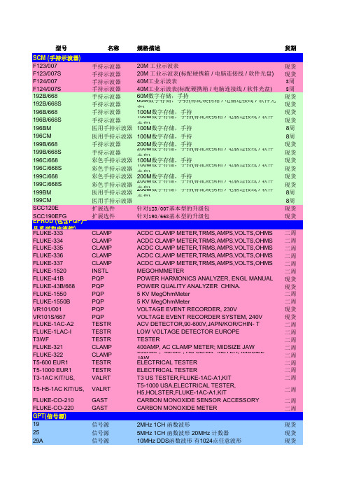
型号名称规格描述货期SCM (手持示波器)F123/007手持示波器20M 工业示波表现货F123/007S手持示波器20M 工业示波表(标配硬携箱 / 电脑连接线 / 软件光盘)现货F124/007手持示波器40M工业示波表8周F124/007S手持示波器40M工业示波表(标配硬携箱 / 电脑连接线 / 软件光盘)8周192B/668手持示波器60M数字存储,手持现货192B/668S手持示波器60M数字存储,手持(标配硬携箱 / 电脑连接线 / 软件光盘)现货196B/668手持示波器100M数字存储,手持现货196B/668S手持示波器100M数字存储,手持(标配硬携箱 / 电脑连接线 / 软件光盘)现货196BM医用手持示波器100M数字存储,手持8周196CM医用手持示波器100M数字存储,手持8周199B/668手持示波器200M数字存储,手持现货199B/668S手持示波器200M数字存储,手持(标配硬携箱 / 电脑连接线 / 软件光盘)现货196C/668彩色手持示波器100M数字存储,手持现货196C/668S彩色手持示波器100M数字存储,手持(标配硬携箱 / 电脑连接线 / 软件光盘)现货199C/668彩色手持示波器200M数字存储,手持现货199C/668S彩色手持示波器200M数字存储,手持(标配硬携箱 / 电脑连接线 / 软件光盘)现货199BM医用手持示波器200M数字存储,手持(标配硬携箱 / 电脑连接线 / 软件光盘)8周199CM医用手持示波器8周SCC120E扩展选件针对123/007基本型的升级包现货SCC190EFG扩展选件针对190/668基本型的升级包现货EPROD (包含PQP产品系列和电流钳)FLUKE-333CLAMP ACDC CLAMP METER,TRMS,AMPS,VOLTS,OHMS二周FLUKE-334CLAMP ACDC CLAMP METER,TRMS,AMPS,VOLTS,OHMS二周FLUKE-335CLAMP ACDC CLAMP METER,TRMS,AMPS,VOLTS,OHMS二周FLUKE-336CLAMP ACDC CLAMP METER,TRMS,AMPS,VOLTS,OHMS二周FLUKE-337CLAMP ACDC CLAMP METER,TRMS,AMPS,VOLTS,OHMS二周FLUKE-1520INSTL MEGOHMMETER二周FLUKE-41B PQP POWER HARMONICS ANALYZER, ENGL MANUAL现货FLUKE-43B/668PQP POWER QUALITY ANALYZER CHINA.现货FLUKE-1550PQP 5 KV MegOhmMeter二周FLUKE-1550B PQP 5 KV MegOhmMeter二周VR101/001PQP VOLTAGE EVENT RECORDER, 230V现货VR101S/667PQP VOLTAGE EVENT RECORDER SYSTEM, 240V现货FLUKE-1AC-A2TESTR ACV DETECTOR,90-600V,JAPN/KOR/CHIN- T二周FLUKE-1LAC-I TESTR LOW VOLTAGE DETECTOR EUROPE二周T3WF TESTR TESTER二周FLUKE-321CLAMP400AMP, AC CLAMP METER; MIDSIZE JAW二周FLUKE-322CLAMP400AMP, 40AMP, AC CLAMP METER; MIDSIZE JAW二周T5-600 EUR1TESTR ELECTRICAL TESTER二周T5-1000 EUR1TESTR ELECTRICAL TESTER二周T3-1AC KIT/US,VALRT T3 US TESTER,FLUKE-1AC-A1,KIT二周T5-H5-1AC KIT/US,VALRT T5-1000 USA,ELECTRICAL TESTER, H5,HOLSTER,FL二周FLUKE-CO-210GAST CARBON MONOXIDE SENSOR ACCESSORY二周FLUKE-CO-220GAST CARBON MONOXIDE METER二周GPT(信号源)19信号源2MHz 1CH 函数波形现货25信号源5MHz 1CH 函数波形 20MHz 计数器现货29A信号源10MHz DDS函数波形有1024点任意波形现货39A信号源30MS/s任意波形现货80信号源50MHz 函数波形现货81信号源50MHz函数/脉冲波形8周195信号源2通道 40MSa/s 任意波形现货195/001信号源4通道 40MSa/s 任意波形现货301信号源300MSa/s单通道通用波形,带4M波形存储器8周302信号源300MSa/s双通道通用波形,带4M波形存储器8周395信号源100MSa/s单通道任意波形现货395-001附件IEEE488接口选件(可直接连接示波器获取波形)8周395-002扩展存储256K扩展内存选件8周Waveforms_DSP2软件任意波形编辑软件现货RPM(电能分析记录仪)-1650系列PR1650-50普通型主机9 通道 (4 电压, 5电流) 标准配置的主机, 包括电源线,电压探头,以太网电缆。
一种便携式消磁设备误差测试仪的研制

一种便携式消磁设备误差测试仪的研制
唐洪贶;陈威;陈可
【期刊名称】《国外电子测量技术》
【年(卷),期】2012(31)3
【摘要】介绍了一种基于模块化思想的消磁设备误差测试仪,用于实现某型消磁设备的综合性能测试。
该系统由三维亥姆霍兹线圈驱动电路、多通道信号采集和信号源3个主要模块组成。
设计了基于自动控制原理的三维亥姆霍兹线圈驱动电路模块;通过滤波放大电路、隔离电路和A/D转换技术实现多通道微弱信号精确采集以及通道间相互隔离;利用直接数字频率合成技术产生标准的测试信号。
用户实际测试结果表明,该误差测试仪精度高,性能稳定可靠,能够满足舰船上及消磁站内对消磁设备综合性能测试的需求。
【总页数】4页(P51-54)
【关键词】消磁设备;误差测试仪;亥姆霍兹线圈;多通道
【作者】唐洪贶;陈威;陈可
【作者单位】桂林电子科技大学电子工程与自动化学院;海军驻桂林地区军事代表室
【正文语种】中文
【中图分类】TP216.1
【相关文献】
1.基于地磁模式组的消磁系统误差测试仪研制磁 [J], 张朝阳;吴飞;史伟
2.一种便携式双端接地断路器机械特性测试仪的研制 [J], 刘慧娟;王啸峰
3.一种便携式岩矿石复电阻率测试仪的研制 [J], 陈兴生; 陈儒军; 申瑞杰; 王小杰
4.一种便携式低压空开综合测试仪的研制及应用 [J], 李阳;冯忠奎;李国成;刘广;于洋
5.一种便携式双端接地断路器机械特性测试仪的研制 [J], 刘慧娟[1];王啸峰[1]因版权原因,仅展示原文概要,查看原文内容请购买。
- 1、下载文档前请自行甄别文档内容的完整性,平台不提供额外的编辑、内容补充、找答案等附加服务。
- 2、"仅部分预览"的文档,不可在线预览部分如存在完整性等问题,可反馈申请退款(可完整预览的文档不适用该条件!)。
- 3、如文档侵犯您的权益,请联系客服反馈,我们会尽快为您处理(人工客服工作时间:9:00-18:30)。
DC Volts
Range: 600V/200V Resolution: 1V/.1V Accuracy: ±(1.0%+3)
AC Current (45-400Hz)
Range: 600A/200A Resolution: 1V/.1V Accuracy: ±(2%+3)/±(2%+5) Crest Factor: Between 2 and 3 add 2% of reading
cable or two 500 MCM (.98" (2.46 cm)) cables up to 38 mm (1.5" in diameter) q DC current zero control for nulling out jaw/sensor offset q Easy, single-handed operation q Easy-view 2000 count digital display q Continuity beeper q Protective soft carrying case and TL75 test leads included q Sleep mode extends battery life q CAT III 600V q Independently tested and approved for UL 3111, CSA 22.2 1010.1 1992 and TUV to EN61010-1:1993
Fluke 36 Clamp Meter
Product Home | Features | Specifications | Models, Options & Accessories | Manuals
AC/DC and True-rms Measurements
Now you can do more with one tool. The Fluke Model 36 is a rugged, reliable clamp meter that measures ac and dc current and volts. This versatile clamp meter offers True-rms sensing and MAX Hold for measuring inrush current or maximum load on a circuit. Tapered jaws and slim profile let you get at cables in tight places. Use it for troubleshooting in industrial, commercial, avionics and marine environments.
© 1995 - 2000 Fluke Corporation Privacy Statement
products/home.asp?SID=0&AGID=0&PID=6057 [2/22/2001 11:31:35 AM]
Fluke 36 Clamp Meter Features
Product Home | Features | Specifications | Models, Options & Accessories | Manuals
AC Volts (45-400Hz)
Range: 600V/200V Resolution: 1V/.1V Accuracy: ±(1.5%+3) Crest Factor: <=3 (pk voltage ±933V)
Ohms
Range: 200 Ohms Resolution: 0.1 Ohms Accuracy: +(1.2%+5) Crest Factor: NA
products/specifications.asp?SID=0&AGID=0&PID=6057 (2 of 2) [2/22/2001 11:33:13 AM]
Fluke 36 Clamp Meter Models, Options & Accessories
Product Home | Features | Specifications | Models, Options & Accessories | Manuals
General Specifications
RF field
RF field = <=1V/m, total accuracy = specified accuracy RF field = 3V/m, total accuracy = specified accuracy + 4% of range
Model NameFl来自ke 36Product Description
Clamp Meter Included Accessories: C36 soft carrying case, TL75 Hard Point™ Test Leads, Operator's Manual, 9V battery (installed)
© 1995 - 2000 Fluke Corporation Privacy Statement
products/orderinfo.asp?SID=0&AGID=0&FID=6054 (2 of 2) [2/22/2001 11:34:07 AM]
Features at a Glance:
q True-rms ac and dc voltage measurement q True-rms AC current q DC current q Resistance q Continuity beeper q Max Hold q Safety-designed hand guard q Carrying case q Jaws accept one 750 MCM (1.2" (3 cm))
products/orderinfo.asp?SID=0&AGID=0&FID=6054 (1 of 2) [2/22/2001 11:34:07 AM]
Models, Options & Accessories
TL81 Y8140A
Deluxe Electronic Test Lead Set 48" Slim Flex Test Lead Set
Available Accessories and Options
Model Name
C36 TL20 TL22 TL23F TL23R TL24 TL26A TL28A TL71 TL74 TL75 TL80
Accessory or Option Description
Soft Case 63" Test Lead Set 63" Right Angle Silicone Test Lead Set Electrical Test Lead Set Electrical Test Lead Set 63" Right Angle/Straight Silicone Test Leads 60" 5-Way Test Lead Set 63" Alligator Clip Test Lead Set Premium DMM Test Lead Assembly 4 mm Diameter Test Leads 48" Hardpoint Test Lead Set Basic Electronic Test Lead Set
q Technical Specifications q General Specifications
Technical Specifications
DC Current
Range: 1000A, 200A Resolution: 1A, .1A Accuracy: 0-600A: ±(1.9%+4), 600-1000A:±(3%+3), 0-200A: ±(1.9%+7)
products/features.asp?SID=0&AGID=0&PID=6057 (1 of 2) [2/22/2001 11:32:13 AM]
Fluke 36 Clamp Meter Specifications
Product Home | Features | Specifications | Models, Options & Accessories | Manuals
Operating temperature
-10°C to 50°C (14°F to 122°F)
Battery life
60 hours continuous, alkaline, sleep mode
products/specifications.asp?SID=0&AGID=0&PID=6057 (1 of 2) [2/22/2001 11:33:13 AM]
Specifications
Size
Weight Warranty
248.9 mm L x 95.2 mm W x 45 mm D (9.8 in L x 3.75 in W x 1.75 in D)
0.45 kg (1 lb.)
One Year Warranty
© 1995 - 2000 Fluke Corporation Privacy Statement