湿法冶金英文部分文献
冶金 毕业设计 外文文献翻译 中英文:铁矿石烧结的最新进展
Recent Developments in Iron Ore Sintering Sintering is the most widely used agglomeration process for iron ores.As the blast furnace is a countercurrent process in which solids descend against a rising gas flow,it is imperative that the ferrous burden is supplied in a lumpy form.It is necessary,therefore,to agglomerate fine ores by sintering or pelletising.Pelletising is usuallypreferred in locations where low grade iron ore is mined and concentrated,particularly in North America.In other regions,natural high grade iron ores are available and sintering offer a lower cost agglomeration route.Consequently,sinteringis by far the more widelyused iron ore agglomeration process outside North America.In the past decade,the annual production of sinter worldwide has ranged from 530 to 586 Mt.Production has fallen since 1989 following the dramatic events which occurred in the Commonwealth of Independent States (CIS,previously the USSR)and other parts of Eastern Europe as their steel industries restructure.The recessionary effects in Europe and Japan have also adversely affected production,although it is expected to recover slowly soon,except in the CIS and Eastern Europe.Although alternative ironmaking processes are emerging,they are not expected to impact significantly on blast furnace production in the nest decade and possibly beyond. Consequently,sintering production should be maintained at its present level for some time to come.Production will decline in Eastern Europe and the CIS as rationalisation continus but grqwth will continue in China,Korea,and Taiwan.Sintering technology has evolved rapidly in the past decade.This has been driven by the need to:(i)decrease energy consumption following the escalation of energy costs in the 1970s;(ii)increase productivilty as older,less efficient plants are closed;(iii)reduce production costs;(iv)reduce environmental impact.In addition to reducing energy consumption,the sinter plant manager has been required to improve product quality to enable energy savings at the blast furnace.In Japan,coke breeze consumption has decreased fromabout 55 kg/t sinter (1973) to 45 kg/t sinter in 1992.Similarly,ignition energy has dropped from about 190 to below 30 MJ/t sinter at some locations.Some European plants have achieved similar reductions in coke breeze consumption,but in general have not been as successful in reducing ignition energy repuirements.Blast furnace coke consumption has also fallen in the past decade,partly to be replaced by fine coal injected through the tuyeres.Part of the coke saving,however,can be attributed to improved sinter quality,notably reducibility and high temperature properties.As the steel industry becomes more competitive,there has been mounting pressure to close older,less efficient plants under rationalisation programmes.On some sites,this has meant the closure of one or some sinter plants and that the surviving plant must increase its productivity in order to satisfy blast furnace demands.In Japan,five plants were closed between 1983 and 1987,but annual producyion was maintained constant,with a consequent increase in productivity.In 1992,the plants at Fos-sur-Mer(Sollac) in France and Kakogawa(Kobe) in Japan achieved the highest productivities of 50t m-3/day.Other ways of reducing costs have also been sought.Iron ore is a major cost component and ironmakers have sought ways to increase their intake of cheaper materials such as fine ores or concentrates and also limonitic ore such as RobeRiver.The use of the maximum amount possible of secondary materials arising on the works such as dusts, sludges, slags, etc.,has also received considerable attention.International concern for the environment has resulted in plant being installed to remove dust and some gaseous emissions from sinter plant process gas.In this respect,Japan has led yhe way with the installation of electrostatic precipitators for dust control and,more significantly,with plants to remove sulphur oxides and nitrogen oxides.Over 50% of sinter plants in Japan have installed desulphurising equipment and two plants have equipment to remove nitrogen oxides.On the other hand,in Europe only the Thyssen Stahl No.4sinter plant (Sehwelgern) has desulphurising equipment.Gas cleaning equipment is expensive and significantly increases the cost of producing sinter.Nevertheless,as legal requirements are introduced in Europe,new control equipment many have to be installedat many plants.In the to optimise the operation and produce the most consistent product,good plant control is essential.Although not discussed here,control and consistency in blending are equally important.In the granulation stage, operators determine their optimum moisture content and then use this for control purposes.Many plants have installed online,infrared(IR)analysers to monitor the moisture concent of the granulated feed.The water addition in the drum is automatically adjusted to maintain the set moisture content.Some Japanese plants use Iranalysres for all feed materials to be compensate for moisture variations at the inlet to the granulationdrum .On some plants,air permeability measurements are performed on granulated feed manually or automatically.Water addition to the drum may then be adjusted depending on the outcome of this measurement.Automatic control is preferred to manual methods since it results in a more rapid response and more consistent feed to the sinter strand.Bethlehem Steel has installed an online permeability apparatus in their feed hopper above the roll feeder at Burns Harbor. At Italsider, preignition permeability is monitored continuously online using a 4 4 m suction box installed immediately before the ignition hood.This has enabled Italsider to increase permeability by 9% since 1980.At NKK,uniformity of ignition is improved using a radiation thermometer installed on the exit side of the ignition hood.It is designed to scan the surface or the bed from side to side in a predetermined cycle.A microcomputer analyses the data and controls the positions of the gas valves in order to minimise surface temperature variation.Sinter chemistry is largely controlled by the blending process thoudgh final trim for CaOand some other elements is possible using bins in the sinter plant.Control of FeOis more complicated but usually involves a change in coke addition or possibly bed height.Chemical analysis is the usual method for determining FeO but a few plants use a magnetic permeability device such as Permagnag,developed by CRM in the late 1960s.This technique is currently in use at British Steel,s Scunthorpe Works.NKK have reported that they are using an FeO meter online atFukuyama Works.In order to complete the sintering process,the strand is operated in such a way to ensure that burnthrough usually occurs at the penultimate windbox.Traditionally,control of burnthrough location is achieved by adjusting the strand speed.Burnthrough itself is difficult to monitor so it is extrapolated from waste gas temperature measurement.Normally,the waste gas temperature is monitored using thermocouples in the last 3,4, or 5 windboxes and the strand operated with maximum temperature in the penultimate windbox.At some of the more modern plants,temperature is measured at several positions in each windbox to eliminate variations across the width of the strand.An average temperature is then used for each windbix.This system is used at Sollac,Fos-sur-Mer, sinter plant with the incorporation of an IRSID model.铁矿石烧结的最新进展烧结是最广泛使用的铁矿石造块法。
钪的循环浸出研究
1. 2
试验方法
[ 5]
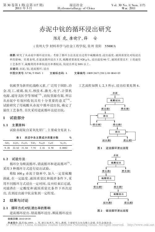
循环分为顺流循环、 错流循环和逆流循环 。 采用 3 种循环方式进行浸出试验。 称取 100 g 赤泥于烧杯中, 加入一定量硫酸 溶液 , 在一定温度、 液固质量比和搅拌条件下 , 采 用不同循环方式浸出一定时间 , 反应结束后过滤, 对滤渣在一定酸度和 液固质量比条 件下再次浸 出, 直到浸出液中钪富集到一定程度。
[ 7]
浸出液中的杂质, 净化浸出液 , 还需进一步研究探 讨。 参考文献 :
[ 1] [ 2] 廖春生 , 徐刚 , 贾江涛 , 等 . 新世纪的战略资源 ∀ ∀ ∀ 钪的提 取 与应用 [ J] . 中国稀土学报 , 2001, 19( 4) : 289 296. 张忠宝 , 张宗华 . 钪的资源与提取技术 [ J] . 云南冶 金 , 2006, 35( 5) : 23 25. [ 3] [ 4] 汪镜亮 . 钪的提 取和回 收 [ J] . 矿产综 合利用 , 1995( 3 ) : 35 42. 司秀芬 , 邓佐国 , 徐廷华 . 赤泥提钪综述 [ J ] . 江西有色 金属 , 2003, 17( 2) : 28 31. [ 5] [ 6] [ 7] 王淀佐 , 邱冠周 , 胡岳华 . 资 源加工 学 [ M ] . 北京 : 科学出 版 社 , 2005: 290 291. 朱炳辰 . 化学反应工 程 [ M ] . 北 京 : 冶 金工业 出版社 , 1997: 98 150. 张桂芳 , 张宗华 , 高利坤 , 等 . 含钪稀土矿提钪浸出剂选择 试 验研究 [ J] . 中国矿业 , 2007, 16( 9) : 65 69.
2
2. 1
结果与讨论
循环方式对钪浸出率的影响 逆流循环浸出、 错流循环浸出、 顺流循环浸出
电池正极材料纳米氢氧化镍的制备新进展_林才顺
电池正极材料纳米氢氧化镍的制备新进展林才顺(中南大学资源环境与建筑工程学院,湖南长沙410083)摘要:综述了电池正极材料纳米氢氧化镍的几种制备方法及其工艺条件和主要特点,描述了纳米氢氧化镍的结构特征及电化学性能,探讨了转化温度、表面活性剂、反应物浓度以及硝酸根离子对形成纳米氢氧化镍颗粒尺寸与形貌的影响,指出纳米氢氧化镍作为电池正极材料具有光明的前景,但对生产技术还需进一步研究。
关键词:纳米材料;氢氧化镍;制备;电化学性能中图分类号:T Q 138.13;T M 911.14文献标识码:A 文章编号:1009-2617(2004)02-0061-05收稿日期:2003-09-04作者简介:林才顺(1973-),男,硕士研究生,主要从事湿发冶金、金属回收及电池正极材料的制备和开发。
作为电池正极材料的氢氧化镍在化学电源的发展过程中占有很重要的地位,被广泛使用到各种镉镍电池、储氢电池、锌镍电池和铁镍电池,所以制备和研究高活性、高容量、高密度的电池正极材料氢氧化镍十分重要。
与普通氢氧化镍相比,纳米氢氧化镍材料具有更优异的电催化活性、高的放电平台、高的电化学容量以及高的密度,因此,它的制备方法和应用特性引起了众多研究者的兴趣和关注,成为竞相研究的热点[1,2]。
目前,许多科技工作者已经研制出多种纳米氢氧化镍的合成方法,如沉淀转化法、均相沉淀法、无水乙醇法、湿法化学合成法、配位沉淀法、离子交换法、微乳液法、高能球磨法以及固相反应法等[3],对其电化学性能和质子扩散行为也有较多研究。
本文从纳米氢氧化镍的制备方法、结构特征和电化学性能3个方面对近年来的研究状况和进展进行综述。
1纳米氢氧化镍的制备方法1.1沉淀转化法沉淀转化法是根据难溶化合物溶度积的不同,通过控制转化条件来限制颗粒生长和防止颗粒团聚,从而获得分散性较好的超微粒子。
通过镍盐和草酸盐反应生成草酸镍盐,控制反应体系温度、搅拌强度、pH 等工艺条件,再加入一定量的表面活性剂和碱液,使之发生沉淀反应。
铜湿法冶金工艺

CLX-50在湿法冶金中的应用
Mextral®CLX-50在湿法冶金中的应用汤启明邹潜丁东升徐志刚李建王朝华(重庆浩康集团金属萃取工程技术研究中心,重庆401221)摘要:对Mextral®CLX-50用作萃取剂、改质剂、协萃剂等方面进行了研究。
Mextral®CLX-50萃取酸性蚀刻液中的铜不受氢离子浓度的影响,在不加碱中和的时候载铜量可远远大于羟肟萃取剂(如Lix®984和Acorga®M5640)的载铜量。
Mextral®CLX-50与Mextral®5640H混合使用,萃取含氯离子料液中的铜,可以充当改质剂的角色,提高Mextral®5640H的反萃能力,从而增加铜的转移量。
Mextral®CLX-50与Mextral®V10混合使用,萃取含镁离子料液中的镍,有协萃作用,在平衡pH值小于5时,可显著增加Mextral®V10的萃取能力。
尤其适合于镁含量很高的料液中镍的萃取。
关键词:萃取, 镍,铜,萃取剂,改质剂,协萃剂引言Acorga®CLX-50是英国帝国化学(ICI)下属的Acorga公司合成的一种萃取剂,可以从高酸度氯化物体系中选择性萃取铜,萃取效率与氢离子浓度无关,负载有机相可用水反萃[1]。
为了直接从酸性蚀刻废液(氯离子和氢离子含量都很高)中萃取铜,我们合成了与Acorga®CLX-50结构相似的萃取剂Mextral®CLX-50,其组成为3,5-吡啶二羧酸二异十三醇酯(50%,w/w)和稀释剂(50%,w/w)。
取得了很好的效果。
羟肟萃取剂(比如Mextral®5640H)从高氯离子浓度料液中萃铜,由于萃取效率降低,从而导致铜净转移降低。
我们发现加入Mextral®CLX-50作改质剂可以在不影响萃取效率的情况下提高反萃效率,从而提高铜净转移量。
Mextral®V10是一种很好的镍萃取剂,尤其适用于钙镁含量很高的镍料液。
刚果(金)中色华鑫湿法冶炼厂提质增效实践

86Metallurgical smelting冶金冶炼刚果(金)中色华鑫湿法冶炼厂提质增效实践钟先林1,张晓峰2,陈胜兵1,刘中华1(1.中色华鑫湿法冶炼有限公司,刚果(金) 利卡西;2.中色矿业香港控股有限公司,刚果(金) 卢本巴希)摘 要:本文介绍了刚果(金)中色华鑫湿法冶炼厂生产实践的情况,分析论证了该厂近年来出现的絮凝剂用量偏高、萃取指标恶化、电流效率下降等问题,详细阐述了该厂针对以上问题所采取的提质增效实践措施、取得的实际效果。
实践证明,通过调整絮凝剂添加工艺流程、改进铜萃取水相堰板调节操作模式、优化电积工序操作环节管理等技术攻关,可有效改善该厂湿法冶炼工艺整体的操作运行环境,提高经济技术指标,降低生产成本,为企业带来良好的经济效益和社会效益。
关键词:刚果(金);提质增效;电流效率;成本控制;生产实践中图分类号:F416.32 文献标识码:A 文章编号:11-5004(2020)13-0086-2收稿日期:2020-07作者简介:钟先林,男,生于1989年,汉族,江西赣州人,硕士研究生,工程师,研究方向:湿法冶金。
提质增效是当前国家对国有企业提出的一项重要的战略性任务要求,也是“十三五”期间中央企业要做好的头号任务。
因此,应深刻认识提质增效的新内涵,加快落实相关改革举措,着力解决影响提质增效的各种制约因素。
中色华鑫湿法冶炼有限公司(以下简称华鑫湿法公司)是中国有色集团在刚果(金)投资的第一家实体企业。
近年来,华鑫湿法始终把加强企业管理和成本管控摆在发展的突出位置和关键位置,以“创新驱动,提升效益”为主题,立足基层班组,发动和组织广大职工结合本企业、本岗位实际,认真查找生产作业和经营管理中存在的突出问题和薄弱环节,积极探索实施生产技术、工艺流程和经营管理等方面的创新。
企业管理水平的不断提高和企业成本管控的不断精准,为公司提高发展质量和效益,提升企业核心竞争力,提供了有力支撑和坚实保障。
钴_镍萃取分离原理与方法_肖超
强度较低 , ∠RPR' 对四面体构型影响不大 。
有机磷类萃取分离钴 、镍的总反应式 可表示为 :
M 2 + +nH2 A2(o)
M A2 (n -i)H2 A 2(o) +2H + 。
在萃取剂大大过量条件下 ,M 为 Co 时 , n =2 ;M 为 N i 时 ,
n =3 。饱 和萃 取时 , 无论 钴 、镍 , n =1 。钴的 萃合 物包 括 四面体和八面 体 2 种构 型 , 而镍 仅有 八面 体构 型 。四 面
Co (Ⅱ)、N i(Ⅱ)生成 外 轨型 络 离子 时 , 如果 为 4 配 位 ,则为 sp3 杂化 , 四面体构型 ;如果是 6 配位 , 则为 sp3 d2 杂化 ,八面体构型 。所以 , Co (Ⅱ)生 成内 轨型 络离 子时 , 易被氧化为 Co(Ⅲ),而 Ni(Ⅱ)较稳定 ,难于氧化 。
2 钴 、镍的萃取分离
2 .1 钴 、镍的磷(膦)类萃取分离
溶剂萃取法是钴 、镍分 离的重 要方法 之一 , 其分离 效 果好 ,金属 收 率 高 , 对 料 液 适 应 性 强 , 过 程 易 于 自 动 控 制[ 5] 。随着新萃取剂 、萃取体系的开发和萃 取理论的逐步 完善 , 溶剂萃取法在钴镍湿法冶金中的应用越来越广泛 。
钴 、镍比较 常见的 配位数为 4 和 6 。配 位数为 6 时 , 配体呈八面体型 。由于配体之间的位置不同 , 5 个轨道 简 并为 2 组 ,电子与配体顶 头接近 的 dz2 、d x2 -y2 作 用强烈 , 能量较高 ,为 6Dq ;而另外的 dxy 、dyz 、dzx 轨道作用力弱 得 多 ,能量较低 , 为 -4Dq 。配位数为 4 时 , 配体可以形 成平 面四方形或正 四面 体构 型 。萃 取剂 的分 子量 较大 , 分 子 间存在较大的 空间 位阻 , 所 以一 般为 正四 面体 构型 。 同 样 ,四面体场亦发生简并 , 但是与八面体场完全相反 , dxy 、 dyz 、dzx 轨道能量 较高 , 为 1 .78Dq , 而 dz2 、dx2 -y2 的轨 道 能量较低 ,为 -2 .67Dq 。
勘查技术与工程文献综述范文
勘查技术与工程文献综述范文英文回答:Exploration Techniques and Engineering Literature Review.Exploration techniques and engineering are fundamental to the discovery and development of mineral resources. Exploration techniques involve the identification and evaluation of geological targets with the potential to host mineral deposits. Engineering plays a vital role in designing and implementing mining operations, ensuring the efficient and sustainable extraction of minerals.Over the years, significant advancements have been made in exploration techniques and engineering, driven by technological innovations and the growing need for sustainable mining practices. In this literature review, we provide an overview of the latest advancements in these fields, focusing on their contributions to mineralexploration and mining operations.Advancements in Exploration Techniques.Geophysics: Advanced geophysical techniques, such as seismic surveys, gravity measurements, and electromagnetic surveys, have enhanced the accuracy and resolution of subsurface imaging, enabling the identification of deeply buried mineral deposits.Geochemistry: Techniques like inductively coupled plasma mass spectrometry (ICP-MS) and laser ablation inductively coupled plasma mass spectrometry (LA-ICP-MS) provide precise elemental data, helping to define geochemical anomalies associated with mineralization.Remote Sensing: Satellite imagery and hyperspectral sensors facilitate the identification of alteration zones and anomalies from surface observations, providing valuable insights into the geology of potential mineral targets.Artificial Intelligence (AI): AI algorithms andmachine learning techniques are being used to analyze vast datasets and identify patterns that may indicate the presence of mineral deposits.Advancements in Engineering.Mine Planning: 3D modeling and simulation tools enable the design of optimal mine layouts, ensuring efficient access to orebodies while minimizing environmental impacts.Mining Methods: Innovative mining methods, such as longwall mining and block caving, have improvedproductivity and safety in underground operations.Mineral Processing: Advanced flotation and hydrometallurgical techniques have enhanced the efficiency of mineral recovery from ores, reducing waste generation.Environmental Management: Sustainable engineering practices, including water treatment systems and waste management techniques, mitigate the environmental impacts of mining operations.Conclusion.The advancements in exploration techniques and engineering have significantly enhanced the ability to discover and develop mineral resources in a sustainable manner. By utilizing these technologies, mining companies can optimize their operations, reduce environmental impacts, and meet the growing global demand for minerals.中文回答:勘查技术与工程文献综述。
谈谈湿法冶金新技术在矿产资源开发中的应用

谈谈湿法冶金新技术在矿产资源开发中的应用张春生1,刘 刚1,2(1.昆明有色冶金设计研究院,云南 昆明 650051; 2.昆明理工大学,云南 昆明 650093)摘 要:随着湿法冶金新技术、特别是细菌浸出技术的不断发展、完善,对不可再生资源进行合理、经济地开发利用,实现可持续发展已成为事实,并得到了日益广泛地应用。
本文简要介绍了湿法冶金新技术在工业中的应用情况及广阔前景。
关键词:湿法冶金;矿产资源;细菌冶金中图分类号:TF111 3 文献标识码:B 文章编号:1004-2660(2006)04-0006-04Application of New Hydrometallurgical Technology in theDevelopment of Mineral ResorucesZHANG Chun-sheng,LI U Gang(1.Kunming Desi gn&Research Institu te of Non-ferrous Metallurgy,Kunming650051;2.Kunmi ng Universi ty of Science and Technology,Kunming650093,China)Abstract:Along with the development and improvement of new hydrometallurgical technology,es-pecially in the field of bacteria leaching process,reasonably and economically developing and utilizing unrene wable resources and implementing the policy of sustainable development already became a truth or guide line accepted by all and widely used with each passing day.The authors introduce the utilization of new hydrometallurgical technology and its bright prospect in industry.Key words:Hydrometallurgy;mineral resources;bacteria metallurgy湿法冶金技术问世以来,在黄金、有色、贵金属等矿产资源的保护性开发、资源的充分利用和环境保护等方面,发挥了巨大的作用,随着该技术的不断发展完善,其前景十分广阔。
地球化学软件PHREEQC在湿法冶金计算热力学中的应用
地球化学软件PHREEQC在湿法冶金计算热力学中的应用黄少波【摘要】以加氢脱硫废催化剂中复合氧化物NiMoO4的酸碱水溶液稳定性为例,采用PHREEQC软件进行了水溶液热力学模拟计算,介绍了PHREEQC软件的计算过程、计算原理、计算步骤及结果分析,并与传统手工算法进行了简单对比.相对于传统手工数学计算方法,PHREEQC具有计算效率高、简单灵活、可解决极复杂多元多相热力学问题等优点,对湿法冶金热力学分析有很大帮助,值得在湿法冶金热力学研究方面推广应用.%With a complex oxide(NiMoO4)in spent catalyst as an example,the software of PHREEQC was adopted to simulate a computation of thermodynamics of aquatic solution. The process,principle and operation steps of computation with PHREEQC, as wells as results analysis were presented in details, which was also compared with traditional calculation methods. It is shown that PHREEQC software is efficient in computation, simple and flexible in operation, which can be used to calculate some extremely complex thermodynamics with multi-component and multi-phase. It is of great help to the thermodynamics analysis in hydrometallurgy and worthy of wide application.【期刊名称】《矿冶工程》【年(卷),期】2018(038)002【总页数】4页(P70-73)【关键词】湿法冶金;计算热力学;地球化学软件;PHREEQC【作者】黄少波【作者单位】长沙矿冶研究院有限责任公司,湖南长沙410012【正文语种】中文【中图分类】TF01湿法冶金过程多在水溶液体系中进行,涉及多元多相反应,为判断矿物分解、沉淀生成、元素分离的反应趋势和条件,需要结合实验研究对反应热力学进行计算分析,以确定溶液pH值、反应温度、反应剂浓度等因素的影响,避免实验研究的盲目性,提高研究工作效率[1]。
硫化砷渣含水率控制试验研究
砷渣 质 量,g;wt为 硫 化 砷 渣 金 属 质 量 分 数,%;ρ
为沉砷后液金属 质 量 浓 度,g/L;V 为 沉 砷 后 液 体
积 ,L.
试 验 所 用 试 剂:Na2S(纯 度 ≥98.0%),聚 合 硫酸铁(Fe质 量 分 数 ≥18.5%),分 析 纯,国 药 集
团化学试剂有限公司.
试 验 主 要 仪 器 :ZNHWGⅡ 型 智 能 恒 温 电 热 套
(郑州科达 机 械 仪 器 设 备 有 限 公 司),Lab2015 型
1 试 验 部 分
司,每小时取2L 样 品,连 续 取 样 3d. 样 品 混 合 均匀,过滤除 去 漂 浮 物,组 成 见 表 1. 可 以 看 出, 铜冶炼废酸中主要含 As、Cl、H2SO4,质量浓度 分 别 为 8.94、0������79、93.62g/L.
表 1 铜 冶 炼 废 酸 的 组 成
一步氧化法制备类球形四氧化三锰
Vol. 39 No. 3(Sum. 171)June 2020第39卷第3期(总第171期)2020牟6月湿法冶金Hydrometallurgy of China一步氧化法制备类球形四氧化三猛李春流,农艳莉,闫冠杰,黎兆明,李 剑,杨茂峰(中信大猛矿业有限责任公司崇左分公司,广西崇左532200)摘要:研究了以硫酸猛、氨水为原料,空气为氧化剂,采用一步氧化法制备类球形四氧化三猛,考察了表面活性 剂对四氧化三猛物相、粒度、振实密度、比表面积、猛质量分数及微观形貌的影响。
结果表明:表面活性剂种类对四氧化三猛物相没有影响,但对粒度、振实密度、比表面积及微观形貌影响显著;以十六烷基三甲基漠化钱为表面活性剂,在硫酸猛浓度2. 0 mol/L 、硫酸猛加料速度15 mL/min 、搅拌速度300 r/min 、反应时间20 h 条件下,可获得综合性能较优的类球形四氧化三猛。
关键词:类球型四氧化三猛;硫酸猛;表面活性剂;粒度中图分类号:TF123;TF792 文献标识码:A DOI : 10. 13355/j. cnki. sfyj. 2020. 03. 012文章编号:1009-2617(2020)03-0232-05近年来,随着新能源汽车等绿色产业的发展,猛酸锂(LiMi^OQ 作为动力型锂离子电池正极材 料,因具有价格便宜、安全性能好、对环境无污染等 优点,越来越受关注生产猛酸锂(LiMn 2O 4)的传统方法主要为高温固相法,此法以电解二氧化 猛为猛源,加入碳酸锂及相应的添加剂,通过固相烧结制成。
但由该法生产的猛酸锂制备的电池材 料存在克比容量低、循环性能差、高温性能不佳等 问题。
研究表明,与二氧化猛相比,采用类球形四氧化三^(Mn 3O 4)为原料制备的LiMn 2O 4性能更 好问。
M rs O a 和LiMn 2O 4均为尖晶石型结构,用Mn 3O 4制备LiMn 2 04时不会发生剧烈的结构变 化,材料结构更加稳定;所制备的LiMn 2 04具有更优异的电化学性能,克比容量、高温性能、循环 性能等方面都得到明显改善:因此,用Mn 3O 4代替电解二氧化猛生产LiMn 2O 4是目前的发展趋 势⑺词。
硫酸体系溶液酸度与pH之间的关系

Vol. 40 No. 2(Sum. 176)Apr. 2021第40卷第2期(总第176期)2021牟4月湿法冶金 .Hydrometallurgy of China硫酸体系溶液酸度与pH 之间的关系郑朝振12,刘三平1(1.矿冶科技集团有限公司,北京100160;2.北京科技大学冶金与生态工程学院,北京100083)摘要:研究了利用电离常数法和活度系数模型法确定湿法冶金过程中硫酸体系溶液酸度,确定硫酸溶液、硫 酸铜溶液和硫酸锌溶液体系H +活度系数、pH 与酸度之间的对应关系,并通过试验进行校验。
结果表明:根据[H +]计算模型建立的硫酸类溶液pH 与酸度的对应关系式可用于计算溶液酸度,计算结果与试验值接近;根据pH-硫酸浓度之间的关系,可由溶液pH 和主要元素浓度推算溶液酸度+关键词:湿法冶金;硫酸;活度系数;酸度;pH 中图分类号:TF801 文献标识码:A文章编号=1009-2617(2021)02-0091-06DOI : 10. 13355/j. cnki. sfyj. 2021. 02. 001湿法冶金过程中,体系的酸度和pH 是金属选 择性浸出、选择性沉淀-1.、萃取分离-.等的基本参数。
酸度一般指总酸度,可通过标准碱定量滴定法 测定,为可滴定酸度。
pH 反映的是H +活度,即已 离解酸的浓度,其大小可用酸度计测定+酸性体系中,硫酸类溶液体系最常见。
硫酸 是弱氧化酸,沸点高(330 °C ),常压下可采用较高温度强化浸出过程,其设备防腐也相对容易,并且 价格低廉便于运输,因此是湿法冶金中的主要溶剂之一 +工业生产中,通常需要根据体系pH 推 算其酸度,然后根据酸度计算需要加入的中和剂、 沉淀剂或皂化剂的量,控制选择性浸出、沉淀或萃 取分离条件。
硫酸是二元酸,存在二级离解+其一级离解很完全,二级离解常数较小,受溶液中硫 酸根等离子浓度影响较大,用pH 计算式直接计算溶液中的H +浓度会造成较大偏差+通过pH 准确推算溶液酸度是工业应用中的难点之一6+根据电离理论7和Pitzer 活度系数计算模型8,建立了 2个关联pH 和酸度的关系式,并通过试 验测定值进行验证,得到不同离子浓度下pH 与酸度之间的关系,以期为工业生产和理论研究提 供参考。
钢铁冶金类英文文献
钢铁冶金类英文文献INTERNATIONAL JOURNAL OF ENERGY RESEARCHInt.J.Energy Res.,22,1049—1054(1998)ENERGY ANALYSIS OF THE STEEL MAKING INDUSTRYMOUSA S.MOHSEN*AND BILAL A.AKASHDepartment of Mechanical&Industrial Engineering,Applied Science Uni v ersity,Amman,11931,JordanSUMMARYSteel making is an energy intensive industry.This work presents and identi?es heat losses of the main components of this industry in Jordan.The heat losses are considerable and range from17to36%of the total energy input.Some heat losses are considered to be recoverable,especially in the furnace and the crucible and mould.Speci?c energy consumption was found to be6)0MJ per ton of steel for the Jordanian steel industry. 1998John Wiley&Sons,Ltd.KEY WORDS energy in steel industry;electric arc furnace;SEC INTRODUCTIONSteel making involves di?erent cycles such as heating,cooling,melting and solidi?cation.It is a highly energy intensive industry.The reduction of energy consumption in this kind of industry is of a special concern.The speci?c energy consumption(SEC)of steel plants for di?erent countries was reported in literature(Bhak-tavatsalam and Choudhury,1995,Choudhury and Bhaktavatsalam,1997).In general,energy savings can be achieved by cutting down direct energy consumption,increasing energy recovery,and adopting the policy of replacing oil products and natural gas in primary steel making with coal and coal-by-products.According toPerlov(1987),increasing the energy e?ciency of the most consuming facilities is achieved by improving the use of secondary energy sources such as minimizing the heat lost in hot waste gases,minimizing the heat radiated through refractory linings of metallurgical furnaces,and cooling the highly thermally stressed components.ALTERNATIVE TECHNOLOGIES AND ENERGY CONSERVATIONIn a recent study it was reported that the developments in iron and steel making took two separate lines (Zervas et al.,1996).The?rst line was concerned with the blast furnace as the principal process for production,and the second was based on the direct reduction and smelting in which iron oxide feedstocks were reduced by gases to metallic iron.The di?erent technologies are summarized in Figure1.Energy consumption in the di?erent stages of steel production is about70%for iron and steel production, 20%for rolling,and10%for miscellaneous(Eketorp,1987).Therefore,the primary step is the main energy consumer in steel making,and most e?orts have been directed towards the blast furnace.Energy e?ciency in the blast furnace can be improved by improving iron-ore benefaction,removing raw?uxes from the blast furnace burden,reducing the ash content of coke,reducing the sulphur content of coke and iron-ore materials,reducing the output fraction of cast iron and ferroalloys,using larger fractions of partly reduced *Correspondence to:Dr.M.S.Mohsen,Department of Mechanical&Industrial Engineering,Applied Science University,Amman,11931,Jordan.Email:bakash@/doc/a31896 2767.html.joCCC0363-907X/98/121049—06$17.50Recei v ed9February1998Figure 1.Summary of di?erent technologiesmetallized raw materials,improving the blending,classi?cation and mechanical strength of iron-ore raw material,increasing the internal pressure in the blast furnace,increasing the blast temperature,and introducing external desulphurization.The scrap charging electric arc furnace (EAF)route of steel making requires considerably less energy than the integrated route.It has been reported,that EAF route is seen to be 40%less energy intensive than the open hearth furnace (OHF)route and less than 50%as energy intensive as the basic oxygen furnace (BOF)route (Lyakishev and Perlov,1987).It has been shown that as the percentage of scrap in the charge increases,the energy e?ciency of the BOF and OHF will increase,since about 90%of the total energy use is associated with the smelting of pig iron.World-wide steel plants switched over to BOF route from OHF route of steel making due to energy conservation considerations.Also,the ingot casting route was replaced by the continuous casting technology (Bhaktavatsalam and Choudhury,1995).THE SCRAP CHARGE EAF ROUTEThe EAF is widely used in many countries for re?ning the quality of steel for industry.The technologies used in steel making in di?erent countries are summarized in Figure 2(Bhaktavatsalam and Choudhury,1995).The scrap-based EAF route of steel production required less energy than the integrated route.Ross(1987)reported that melting involves the transfer of 1)1MBtu to each ton of scrap (1)16GJ ton \ ),and in average practice about 2)4MBtu is consumed per ton of liquid steel (2)53GJ ton \ ).For example,the scrap remelting is playing an important role of reducing energy consumption in steel making industry in Italy,it was reported that the production of new steel requires about 18GJ ton \ of liquid steel,while the production of remelted steel from scrap requires 6)5GJ ton \ of liquid steel (Bisio,1993).The theor-etical quantity of heat necessary to melt the scrap and to bring the steel to the tapping temperature is about 345kW h ton \ (Scotti,1990).Although,in practice,the amount needed is higher due to non-homogeneity of the scrap,heat is lost during charging phase of the scrap.Heat is also lost through the fettlings,the walls and the water-cooling crown,the outlet of hot gases from the clefts of the crown,and reactance of the electric furnace and consequent lower exploitation of the active energy and increase of electric losses.1050M.S.MOHSEN AND B.A.AKASHENERGY ANALYSIS OF THE STEEL MAKING INDUSTRY1051Figure2.Routes used in steel making in di?erent countriesThe main measures for saving energy in the EAF steel making are:recovery of heat from o?gases with its use to preheat scrap,using oxygen,increasing the voltage of the transformer,installing electrodes with protective coatings,reducing furnace downtimes,automatic controls for the voltage and power factor,and for the position of the electrodes,water cooling of the sides and insulation,and increasing the volume of metal treated in the ladle.The production of liquid steel in the electric furnace absorbsthe highest proportion of the total energy consumption in the scrap charge EAF route.A proportion of67%has been reported(Poggi,1990).A mathematical model which integrates the electrical model with the thermal model has been developed for the performance of an electric arc furnace(Chirattananon and Gao,1996).The in?uence of operational parameters on the overall energy performance and productivity of an arc furnace operation has been demonstrated.The most prominent change in shaping technology is the continuous casting since it o?ers important bene?ts in product quality for most products because of its uniformity and reduction of defects during solidi?cation.Continuous castings has large immediate energy bene?ts.It was reported that the direct savings are about1688MJ ton\ of rough shaped steel(Ross1987).About0)17ton more liquid steel per ton of shaped steel is required with the ingot casting than for continuos casting.The savings due to this requirement are about3060MJ ton\ of rough shaped steel.Energy can be saved in the hot rolling stage,in current practice,almost4220MJ ton\ of hot rolled product is used for reheating(Ross,1987).Improvements in the reheat furnace through automatic control based on sensing the surface temperatures of the slab and separately controlling di?erent zones of the furnace heat recovery including waste heat boilers,improved insulated water-cooled skids,and improvements in the envelope will reduce energy consumption.STEEL INDUSTRY IN JORDANThe steel making industry in Jordan is based on recycling of iron and steel.It involves melting of scrap in the electricfurnace.This type of process takes place as a result of the electric arc which is generated betweenthe electrode and the scrap.As an example,the Jordanian Iron &Steel Industry Co.facility plant has been investigated and analysed.The 120ton-per-day capacity production line consists mainly of the smelting by EAF and the shaping part.Block diagrams of the production line are shown in Figures 3and 4.Electricity is primarily used to operate the rolling mill and electric arc furnace.The electric arc furnace uses 700kW h ton \ to melt the scrap,which consists of about 62%of the total energy consumption.The energy content of each stream entering and leaving the unit in the smelting section,was calculated from the appropriate site of measurement.Magnitudes of all heat losses were calculated and presented in Figures 5—7.Based on energy balance of each unit,it is found that 914MJ ton \ (36%of total heat input)are lost in the furnace.Heat losses in the crucible and mould add up to 439MJ ton \ (17%of total heat input).On the other hand,651MJ ton \ is lost in the cooler (26%of total heat input).Recovery of the heat content of the cooling water can be accomplished by steam generation and preheating the scrap.From heat content di?erence in the cooler,the initial temperature of the scrap can be raised approximately to about 800°C.The shaping involves casting th e liquid steel into rough shapes,then these rough shapes are reheated and rolled into reinforcement steel bars.The casting,reheating furnace and rolling mills for steel rods absorb approximately 65%of the total energy consumption of the production line as shown in Table 1.The energy consumption of this stage is 70kW h ton \ (0)25GJ ton \ )of electricity and 70)5kg of fuel oil per each ton of steel (3)00GJ ton \ ).SEC of the Jordanian steel making industry is thus obtained by the procedure described by Choudhury and Bhaktavatsalam (1997).It is found to be equal to 6.0GJ ton \ of steel.It is presented in Figure 8as compared to SEC of other countries.It is lower than those values of other countries,since steel industry in Jordan is based on remelting or recycling of scrap.However,steel making in other countries presented in Table 1is based from manufacturing of steel from raw materials.Therefore,energy consumption and thus,SEC is lower for Jordanian steel makingindustry.Figure 3.Block diagram of scrap-based EAFroute.Figure 4.Block diagram of temperature distribution of EAFrouteFigure 5.Energy balance inEAFFigure 6.Energy balance in crucible and mould 1052M.S.MOHSEN AND B.A.AKASHFigure 7.Energy balance in coolerTable 1.Energy consumption (GJ ton steel \ )ElectricityFuel oil Gas oil Total EAF2)52——2)52Casting,reheating furnace and0)253)000)053)25rolling millOthers0)18——0)18Total 2)953)000)056)00Figure 8.Speci?c energy consumptionCONCLUSIONHeat losses occur along the line of production of the steel making industry.About 36%of total heat input is lost in the furnace.This is a recoverable heat which should not be wasted.17%of total heat input is lost in the crucible and mould.Some of it can be recovered or used in processing of steam.Over 26%of heat is rejected in the cooler.The recovery of heat of last process could be di?cult to achieve,except for space heating or ENERGY ANALYSIS OF THE STEEL MAKING INDUSTRY 10531054M.S.MOHSEN AND B.A.AKASHreheating of scrap to higher initial temperature.Due to the nature of steel making in Jordan is based on remelting of pellets or scrap,SEC is found to be equal to6)0GJ ton\ .It is lower than SEC of other industrialized countries.REFERENCESBhaktavatsalam,A.K.and Choudhury,R.(1995).‘Speci?c energy consumption in the steel industry’,Energy,20,1247—1250. Bisio,G.(1993).‘Exergy method for e?cient energy resource use in the steel industry’,Energy,18,971—985.Chirattananon,S.and Gao,Z.(1996).‘A model for the performance evaluation of the operation of electric arc furnace’,Energy Convers. Mgmt.,37,161—166.Choudhury,R.and Bhaktavatsalam,A.K.(1997).‘Energy ine?ciency of Indian steel industry-scope for energy conservation’,Energy Convers.Mgmt.,38,167—171.Eketorp,S.(1987).‘Energy considerations of classical and new iron-and steel-making technology’,Energy,12,1153—1168. Lyakishev,N.P.and Perlov,N.I.(1987).‘Technological progress and energy conservation in the iron and steel industry of the U.S.S.R.’Energy,12,1169—1176.Perlov,N.I.(1987).‘Technological approach es to energy saving in blast-furnace operations in the iron and steel industry of the U.S.S.R.’, Energy,12,1177.Poggi,S.(1990).‘Present situation and trend of energy savings in Italian steelmaking’,Appl.Energy,36,47—49.Ross,M.(1987).‘Industrial energy co nservation and the steel industry of the United States’,Energy,12,1137—1152.Scotti,G.(1990).‘Prospects for energy saving in Italian iron and steel industry using electric furnaces’,Appl.Energy,36,51—54. Zervas,T.,McMullan,J.T.and Williams,B.C.(1996).‘Deve lopments in iron and steel making’Int.J.Energy Res.,20,69—91.。
关于焊接方面的英文文献
Journal of Materials Processing Technology180(2006)216–220Studies on softening of heat-affected zone of pulsed-currentGMA welded Al–Zn–Mg alloyGaofeng Fu∗,Fuquan Tian,Hong WangSchool of Materials and Metallurgy,Northeastern University,Shenyang110004,ChinaReceived15December2005;received in revised form9June2006;accepted12June2006AbstractStudies on the softening behavior of the7005alloy by means of real welding experiments and heat-affected zone(HAZ)simulation have been conducted.Softening in the HAZ is found to occur above a peak temperature of about200◦C.It was found that the heat-affected zone of the alloys can be divided into two sub-zones according to their different mechanism of softening:the dissolution zone and the overageing zone.The dissolution zone is characterised by dissolution of precipitates and covers the peak temperature range above380◦C.The overageing zone is characterised by growth of precipitates and covers the peak temperature range between230and380◦C.The hardness in the heat-affected zone can be recovered by post-weld heat treatment,especially in the dissolution zone.Artificial ageing is more effective than natural ageing considering the recovery of the hardness.©2006Elsevier B.V.All rights reserved.Keywords:Aluminum alloys;Heat-affected zone;Softening;Welding;Thermal simulation1.IntroductionThe Al–Zn–Mg alloy has wide acceptance in fabrication of lightweight structures requiring a high strength-to-weight ratio, such as storage tanks of space rockets,transportable bridge gird-ers and railway transport systems[1–3].Within the Al–Zn–Mg alloy system the7005alloy is a medium-strength and weldable alloy which contains mainly 4.5%Zn,1.4%Mg and some amounts of manganese.The precip-itation sequence usually proposed for alloys with similar Zn and Mg contents to those of the7005alloy is[4]:α-supersaturated solid solution(␣-SSS),spherical Guinier–Preston(GP)zones, the transition phase( phase)and the intermetallic compound (phase).␣-SSS is retained after quenching to room tempera-ture(RT).Thefirst stage of decomposition occurs by aging at RT for a few days(natural aging),which results in the forma-tion of GP zones.The GP zones and the transition phase( ), in the form of semi-coherent precipitates,are primarily respon-sible for hardening of the alloys.The intermetallic compoundis non-coherent precipitates.It is formed either by growth of the transition phase or by direct precipitation from the solid solu-tion at high temperature and does not contribute to the hardening effect of the alloys[5–7].∗Corresponding author.Tel.:+862483681325;fax:+862423906316.E-mail address:f137********@(G.Fu).In any structural application of this alloy consideration of its weldability is of utmost importance as welding is largely used for joining of structural components.During welding,different microstructural changes are likely to occur in the heat-affected zone(HAZ)of the weld,such as recrystallisation,grain growth and modifications of precipitates.With respect to strength,grain growth plays an important role in the case of non-heat-treatable aluminium alloys,but is of minor importance in the case of heat-treatable aluminium alloys.In the case of heat-treatable aluminium alloys,the strength is mainly influenced by modifi-cation of precipitates[8–10].Although the general transformation behaviour of Al–Zn–Mg alloys is known,detailed knowledge about HAZ softening in some individual alloys is lacking.The purpose of this paper is to obtain fundamental insight in the HAZ softening characteristics of the7005alloy during pulsed-current GMA welding,and to find out how the softening is affected by heat input and post-weld heat treatment.2.Materials and experimental procedure2.1.MaterialsThe base material used in this study is7005alloy in the form of12-mm thick plates in T6condition.The chemical composi-tions of the material are(in wt.%):Al–4.5Zn–1.4Mg–0.4Mn,0924-0136/$–see front matter©2006Elsevier B.V.All rights reserved. doi:10.1016/j.jmatprotec.2006.06.008G.Fu et al./Journal of Materials Processing Technology 180(2006)216–220217Table 1Welding parametersLow heat input conditionsHigh heat input conditions Arc voltage (V)2525Arc current (A)200200Travel speed (cm/min)6030Shielding gasArgon Argon Gas flow rate (l/min)1414Filler wire,diameter (mm)ER5356,1.2ER5356,1.2PolarityDCEP DCEP Process efficiency (%)6565Heat input (J/mm)5001000also containing 0.2Cr,0.02Ti,Fe <0.4,Si <0.35and Cu <0.1.The specimens were machined from the as-extruded 7005bars.2.2.HAZ simulationHAZ simulation was carried out by imposing thermal cycles on a series of small specimens,having dimensions 10mm ×10mm ×60mm.The specimens were machined from the plate material,the longest dimension parallel to the rolling direction of the plate.Two sets of welding conditions were selected for simulation,corresponding to heat inputs of 500and 1000J/mm,respectively (Table 1).The HAZs in the case of both heat inputs were simulated by thermal cycles with peak temperatures between 150and 600◦C,which for the given heat input represent specific locations in the HAZ.The thermal cycles used in the HAZ simulation were calculated with the modified Rosenthal model for two-dimensional heat flow.The properties of the HAZ are usually expressed either as a function of peak temperature or as a function of distance from the fusion boundary.In view of this,it is convenient to know the relation between the peak temperature and the distance from the fusion boundary.This relation was determined for the two heat inputs used in this work (500and 1000J/mm).The results are shown in Fig.1.Fig.1.The relation between peak temperature and the distance from the fusion boundary for two heat inputs (500and 1000J/mm).2.3.Welding experimentsTo be able to compare the results obtained in the case of sim-ulation with the results obtained in the case of real welding,a number of single V-butt welds were made in 12-mm thick plates,using the same welding conditions as those used to calculate the thermal simulation cycles (Table 1).Welding was carried out in a direction normal to the rolling direction of the plate,using a mechanized pulsed-current GMA welding system.Before weld-ing the surface of the workpiece was cleaned by a stainless steel brush in order to remove the oxide layer.2.4.Heat treatmentIn order to examine the influence of heat treatment on the microstructure and properties of the materials,the simulated and welded specimens were subjected to one of the following heat treatments:1.natural ageing (4months at room temperature);2.artificial ageing (24h at 120◦C);3.step ageing (8h at 100◦C +24h at 150◦C).2.5.Examination of hardness and microstructureHardness measurements of both the simulated and welded specimens were carried out using a Vickers hardness machine (5kg load).To study the microstructure of the simulated and welded specimens cross-sections were made,which were subsequently ground and etched using Keller solution.The microstructure was primarily examined by means of optical microscopy (Neophot II).Additionally,transmission electron microscopy (TEM)was carried out using a Philips EM400.The thin foils required for the TEM examination were prepared by jet polishing.3.Results and discussion 3.1.Softening of the HAZIn order to determine the effect of welding on the hardness of the 7005alloy,specimens were simulated and examined follow-ing the procedure described in the previous section.In Fig.2the hardness of the alloys immediately after simulation is plotted as a function of the peak temperature for the situation correspond-ing with a heat input of 500J/mm.The figure shows that softening occurs when the peak tem-perature is higher than about 200◦C,which is equivalent with softening in a zone having a width of about 12mm adjacent to the fusion boundary.As already mentioned above,softening of the HAZ in heat-treatable aluminium alloys is directly related to modification of precipitates.3.2.Modification of precipitatesTo be able to obtain additional information about the pre-cipitation behaviour of the alloys due to welding,transmission218G.Fu et al./Journal of Materials Processing Technology 180(2006)216–220Fig.2.Hardness as a function of peak temperature of simulated specimens directly after simulation (heat input 500J/mm).electron microscopy (TEM)was carried out on both as-received and simulated specimens.Fig.3shows TEM micrographs of 7005specimens simulated at different peak temperatures.In Fig.3(a)the microstructure of the non-simulated parent metal is shown in which small precipitates are visible.During sim-ulation up to a peak temperature of 200◦C the precipitates remain virtually unchanged (Fig.3(b)).However,simulation at a peak temperature of 300◦C,leads to dissolution and growth of precipitates (Fig.3(c)).When the peak temperature exceeds 400◦C,all precipitates are dissolved (Fig.3(d)).On the basis of these observations it may be concluded that the loss of hardness in the HAZ is due to dissolution and/or growth ofprecipitates.Fig.4.Hardness as a function of peak temperature of simulated specimens of 7005alloy for two welding conditions.After simulation,the specimens were treated by artificial ageing.To separate the softening effect due to dissolution from that due to the growth of precipitates,simulated specimens were given an artificial ageing treatment.The idea behind this approach is that dissolved precipitates will be re-formed to hardening precipitates by ageing.The hardness after arti-ficial ageing is plotted as a function of peak temperature in Fig.4.In Fig.4,it can be seen that at temperatures above about 380◦C the hardness is fully recovered to the level of the parent metal by the ageing treatment.Apparently,hardening precipi-tates are formed from the solid solution under these conditions.In the temperature range between about 230and 380◦CtheFig.3.TEM micrographs of simulated specimens directly after simulation:(a)parent metal,(b)peak temperature 200◦C,(c)peak temperature 300◦C and (d)peak temperature 400◦C.G.Fu et al./Journal of Materials Processing Technology 180(2006)216–220219hardness is only partially recovered,which indicates that in this temperature range overageing (growth of precipitates)takes place.The most severe overageing occurs at peak temperatures around 320◦C.It should be noted that for both heat inputs over-ageing occurs within approximately the same peak temperature range,230–380◦C,and that the most severe overageing occurs at the same peak temperature (about 320◦C).On the basis of the foregoing observations,it is possible to divide the HAZ into two sub-zones:the dissolution zone and the overageing zone.The boundary between the two sub-zones corresponds with a peak temperature of about 380◦C.The results obtained on the 7005alloy show that the heat input does not have a measurable influence on the location and size of the sub-zones,but significantly affects the magnitude of overageing.In order to find out at which peak temperature the precipi-tates of the parent metal will be completely dissolved,specimens were simulated at high peak temperatures,cooled down at fast cooling rate to avoid the possible influence of harmful precipita-tion,and artificially aged.After this treatment the hardness was measured.It was found that complete recovery of the hardness occurs at peak temperatures higher than 380◦C.This implies that the temperature which divides the dissolution zone and the overageing zone is 380◦C for the 7005alloy.3.3.Influence of post-weld heat treatmentAs pointed out in the previous section,part of the hardness loss in the HAZ can be recovered by an ageing treatment.In order to sort out the effect of ageing in more detail the hard-ness of the simulated HAZ was measured after different ageing treatments.In Fig.5the hardness of the simulated HAZ is plotted as a function of the distance from the fusion boundary for different heat treatment conditions.Generally speaking,artificial ageing and step ageing result in the best hardness recovery in the high peak temperature area (close to the fusion boundary).It appears that the possibility of property recovery through natural ageing is limited compared with the other two artificial ageing treatments.Even after 4months the hardness oftheFig.5.Hardness as a function of the distance from the fusion line for specimens simulated with fast cooling rate followed by artificialageing.Fig.6.Hardness profiles of simulated and welded material (low heat input con-ditions).naturally aged specimen still has not reached the level obtained by artificial ageing.As can be seen,step ageing leads to some overageing of the unaffected zone,which is presumably due to the relatively high ageing temperature during the last step of this treatment.3.4.Verification of HAZ simulationTo be able to compare the results obtained by means of simulation with the results obtained by real welding,a series of GMA welding experiments was carried out under identical thermal conditions (Table 1).In Fig.6the hardness profiles of both the simulated and the welded material are presented (low heat input conditions).It appears that excellent agreement exists between the results of simulation and the results of real weld-ing,which can be considered as a justification of the simulation approach.4.Conclusions•The HAZ of the 7005alloys can be divided into two sub-zones according to their different mechanism of softening:the dissolution zone and the overageing zone.•The dissolution zone is characterised by dissolution of precipitates and covers the peak temperature range above 380◦C.•The overageing zone is characterised by growth of precipi-tates and covers the peak temperature range between 230and 380◦C.•HAZ hardness can be recovered by post-weld heat treatment.Artificial ageing is more effective than natural ageing consid-ering the recovery of the hardness.References[1]M.P.Wang,Z.W.Wang,Z.N.Wang,L.Zhou,Chin.J.Nonferrous Met.11(6)(2001)1069(in Chinese).[2]S.Sasabe,J.Light Met.Weld.Construct.40(2002)445.[3]P.Allais,P.Mercher,Met.Mater.8(1972)343.[4]R.Ferragut,A.Somoza,A.Tolley,I.Torriani,J.Mater.Process.Technol.141(1)(2003)35.220G.Fu et al./Journal of Materials Processing Technology180(2006)216–220[5]M.Kanno,l.Araki,Q.Cui,Mater.Sci.Technol.10(7)(1994)599.[6]H.M.Hussain,P.K.Ghosh,P.C.Gupta,N.B.Potluri,Weld.J.75(7)(1996)209.[7]M.Iqbal,M.A.Shaikh,M.Ahmad,K.A.Shoaib,J.Mater.Sci.Technol.16(3)(2000)319.[8]T.Ma,G.den Ouden,Int.J.Joining Mater.8(3)(1996)105.[9]H.M.Hussain,P.K.Ghosh,P.C.Gupta,P.N.Babu,Int.J.Joining Mater.9(2)(1997)74.[10]Nicolas,Myriam,Deschamps,Alexis,Mater.Sci.Forum396–402(2002)1561.。
HAuCl_4溶液的净化_Ag_Pb的去除
第28卷第2期(总第110期)2009年6月湿法冶金Hydrometallurgy of China Vol.28No.2(Sum.110)J une 2009HAuCl 4溶液的净化———Ag 、Pb 的去除蒋志建(北京有色金属工业总公司供销公司,北京100026)摘要:通过分析氧化还原电位,明确了还原海绵金中银、铅含量偏高的原因,探讨了从HAuCl 4溶液中去除银、铅的几种方法。
通过控制沉淀时的p H ,认为硫化法是除银、铅的最佳选择。
关键词:HAuCl 4溶液;净化;硫化法中图分类号:TF803.25 文献标识码:A 文章编号:100922617(2009)022*******收稿日期:2007205209作者简介:蒋芝建(1949-),男,江苏宜兴人,高级工程师,主要从事有色金属冶炼及从废料中回收贵金属的研究。
在粗金、杂金的提纯、精炼过程中,要去除许多杂质。
而要去除杂质,则需控制各杂质的氧化还原电位。
目前国内对粗、杂金电位控制还原均采用2步法,第1步将氧化还原电位控制在700mV 左右,使97%左右的金首先还原出来,得到高品位海绵金,其中w (Au )≥99.997%。
余液再进行二次还原,控制氧化还原电位在400mV 左右,此时,溶液中的金已全部还原出来,而大部分贱金属还未开始还原,留于溶液中。
这种方法对大部分贱金属来说,确实有明显的除杂效果。
表1为杂质元素的氧化还原电位。
表1某些杂质元素的氧化还原电位低电位杂质电位ε0/mV高电位杂质电位ε0/mVCu 2+/Cu +337Ag 2+/Ag +1369Cu +/Cu +520Ag +/Ag +800La 3+/La -2520Pb 4+/Pb +800Ce 3+/Ce -2480Pd 4+/Pd +987Cr 3+/Cr-740Pt 2+/Pt+1200从还原过程中所控制的还原终点电位来看,氧化还原电位为700mV 左右时,一次还原结束,表1中的Cu ,Cr ,La ,Ce 等低电位杂质由于其氧化还原电位远远低于所控制的电位值,故不被还原。
《湿法冶金》入编《中文核心期刊要目总揽》2011年版
《湿法冶金》入编《中文核心期刊要目总揽》2011年版
佚名
【期刊名称】《湿法冶金》
【年(卷),期】2012(31)2
【摘要】依据文献计量学的原理和方法,经研究人员对相关文献的检索、统计和分析,以及学科专家评审,《湿法冶金》入编《中文核心期刊要目总揽》2011年版
(即第6版)之冶金工业类核心期刊。
评选核心期刊的工作是运用科学方法对各
种刊物在一定时期内所刊载论文的学术水平和学术影响力进行综合评价的一种科研活动,研究工作量浩大。
北京地区十几所高校图书馆、中国科学院国家科学图书馆、中国社会科学院文献信息中心、中国人民大学书报资料中心。
【总页数】1页(P80-80)
【关键词】中文核心期刊;湿法冶金;文献计量学;中国社会科学院;高校图书馆;中国
科学院;中国人民大学;科学方法
【正文语种】中文
【中图分类】TF111.3
【相关文献】
1.《中文核心期刊要目总览》(2011年版)《中文核心期刊要目总览》(2011年版)
综合性医药卫生类核心期刊表(239种,进入37种) [J],
2.本刊入编《中文核心期刊要目总览》2011年版(即第六版)核心期刊 [J],
3.《工业工程》入编《中文核心期刊要目总览》2011年版核心期刊 [J],
4.本刊入编《中文核心期刊要目总览》2011年版(即第六版)核心期刊 [J],
5.本刊入编《中文核心期刊要目总览》2011年版核心期刊 [J],
因版权原因,仅展示原文概要,查看原文内容请购买。
用过硫酸钠氧化富集钴镍渣中的钴
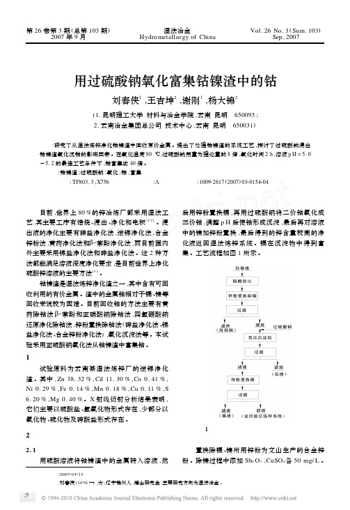
目前 ,世界上 80 %的锌冶炼厂都采用湿法工 艺 ,其主要工序有焙烧 、浸出 、净化和电积[122] 。浸 出液的净化主要有砷盐净化法 ,逆锑净化法 ,合金 锌粉法 ,黄药净化法和β2萘酚净化法 ,而目前国内 外主要采用锑盐净化法和砷盐净化法。这 2 种方 法都能满足溶液深度净化要求 ,是目前世界上净化 硫酸锌溶液的主要方法[3] 。
4 结论
Na2 S2 O8 作为强氧化剂可用于氧化钴镍渣中 的钴 ,其用量为理论量的 8 倍 ,在 80 ℃下氧化 2 h , 并控制溶液 p H 在 5. 0~5. 2 之间 ,得到钴质量分 数为 18. 037 %的富钴渣 ,可用于提取钴。
图 5 氧化温度对金属氧化率的影响
3. 3 时间的影响 氧化温度 80 ℃,过硫酸钠加入量为理论量的
钴镍渣是湿法炼锌净化渣之一 ,其中含有可回 收利用的有价金属 。渣中的金属钴相对于镉、镍等 回收来说较为困难 。目前回收钴的方法主要有黄 药除钴法 β, 2萘酚和亚硝酸钠除钴法 ,四氢硼酸钠 还原净化除钴法 ,锌粉置换除钴法 (砷盐净化法 、锑 盐净化法、合金锌粉净化法) ,氧化沉淀法等 。本试 验采用亚硫酸钠氧化法从钴镍渣中富集钴 。
不同温度下 ,过硫酸钠加入量为理论量的 7 倍 ,隔 20 min 用氢氧化钠中和至 p H 为 5. 0 ~ 5. 2 ,搅拌 2 h 。试验结果如图 5 所示 。可以看出 , Fe , Mn , Ni 的氧化受温度影响不大 ,而 Co 的氧 化随温度变化明显 。80 ℃时 ,Co 氧化率最高 ,近 于 100 %。因此 ,氧化温度以 80 ℃为宜 。
2) - 0. 5 < p H < 3 时 ,Co2 + 被氧化成 CoO2 。 3) 3 < p H < 6 时 , Co2 + 被氧化成 Co3 + ,并以 Co (O H) 3 形式沉淀 。 4) 6 < p H < 6. 2 时 ,Co2 + 被氧化成 Co3 O4 。 试验中 ,用氢氧化钠溶液控制 p H 在 5. 0 左 右 ,所以 Co2 + 以 Co (O H) 3 形式沉淀 。反应式为 : S2 O28 - + 2Co2 + + 6 H2 O 2SO24 - + 2Co (O H) 3 ↓+ 6 H + 。 在此条件下 ,渣中的 Fe ,Mn ,Ni 也与过硫酸 钠反应形成氢氧化物或氧化物沉淀 。反应式为 : S2 O28 - + 2 Fe2 + + 6 H2 O 2SO24 - + 2 Fe (O H) 3 ↓+ 6 H + , S2 O28 - + Mn2 + + 2 H2 O 2SO24 - + MnO2 ↓+ 4 H + , S2 O28 - + 2Ni2 + + 4 H2 O 2SO24 - + 2NiOO H ↓+ 6 H + 。
重要氯化湿法冶金流程--克利尔流程
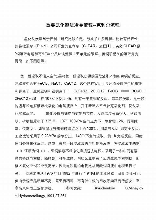
立志当早,存高远重要氯化湿法冶金流程--克利尔流程氯化铁浸取易于控制,研究比较广泛,形成了许多流程。
比较有代表性的是杜瓦尔(Duval)公司开发的克利尔(CLEAR)流程[1],英文CLEAR 是“铜浸取电解和再生”这个反映该流程主要单元的缩写。
黄铜矿精矿的浸取分为两段,如下图所示。
第一段浸取不通人空气,是将第二段浸取获得的浸取液引入和新黄铜矿反应,浸取液中含有FeCl3、NaC1、CuC12。
这个过程实际上是还原浸取液中的高铁和铜离子,生成亚铁和亚铜离子:CuFeS2+2CuC12+FeCl3 ==== 3CuCl+2FeC12+2S 在107℃下反应4h,约有一半黄铜矿反应。
第二段浸取,是一段的渣与经电解槽阳极氧化的电解液反应,并不断通入空气补充氧化剂,使铁氧化水解沉淀。
氧化浸取的速度与矿物的粒度、反应温度关系很大。
试验表明,矿物粒度小于325 目,107℃100kPa 空气压力下,氧化需12h。
而用纯氧,仅需6h。
如果温度升高到硫熔点之上的130℃,用氧气0.5h 即完全反应。
工业试验采用了0.28MPa 的氧分压,140℃下空气浸取,约1h 完成反应,同时使部分铁氧化沉淀。
过滤下来的一段浸取液再与粗铜粉反应,将浸取液中的铜(II)还原为铜(I)。
亚铜溶液不经净化直接送去电积。
采用了一种中间有隔膜的特殊电解槽,隔膜是一种半透膜。
阴极区亚铜离子还原生成电解铜粉,阳极区氧化亚铜和亚铁离子。
因此电积铜的电耗比从硫酸铜溶液中电积要低得多。
克利尔法从1976 年到1982 年进行了91t/d 的工业试验,证明流程可行,但由于铜产品质量不高,需要再精炼,再有伴生银的回收等问题尚待解决,至今尚未完成工业化进程。
参考文献: 1.Kyuchoukov G,Mihaylov Y,Hydrometallurgy,1991,27,361。
- 1、下载文档前请自行甄别文档内容的完整性,平台不提供额外的编辑、内容补充、找答案等附加服务。
- 2、"仅部分预览"的文档,不可在线预览部分如存在完整性等问题,可反馈申请退款(可完整预览的文档不适用该条件!)。
- 3、如文档侵犯您的权益,请联系客服反馈,我们会尽快为您处理(人工客服工作时间:9:00-18:30)。
Table 3 Phases analysis of reverberatory slag from Refimet
Phase
Composition
Majority phases Vitreous phase
Fayalite
Silicate of Fe, Ca and K with Al, Ti, Zn and traces of Cu Iron silicate with Ca, K, Al, Ti and Zn
10
Ca
Ka
PET
10
As
La
TAP
10
Al
Ka
TAP
10
Si
Ka
TAP
10
Na
Ka
TAP
20
Voltage ŽKV.
15 15 25 15 15 15 15 15 15 15 15 15
Standard
chalcopyrite sphalerite chalcopyrite rutile Cr2 O 3 chalcopyrite orthoclase wollastonite GaAs orthoclase orthoclase albite
) Corresponding author.
0304-386Xr98r$19.00 q 1998 Elsevier Science B.V. All rights reserved. PII S 0 3 0 4 - 3 8 6 X Ž 9 8 . 0 0 0 1 0 - 3
88
O. Herreros et al.r Hydrometallurgy 49 (1998) 87–101
This investigation includes a characterization of Chilean copper smelter slags and a study of the leaching of reverberatory and flash furnace slags in Cl2rCly systems. This procedure could be relevant because the treatment of copper solutions with high chloride concentration by solvent extraction is in operation in Chile on an industrial scale wProcess of Empresa Minera de Mantos Blancos, personal communication.x. Large quantities of slags have accumulated over the years at Chilean smelters and is continuing, since for every tonne of copper, approximately 2–3 tonnes of slags are produced. In Chile there are five smelters: Ventanas, Caletones, Chuquicamata, Refimet and Paipote, processing 1 650 000 tonnesryr of copper concentrates.
2. Experimental procedure
2.1. Materials
In this investigation, a reverberatory and a flash smelting slag were used. These were provided by Refimet and Codelco Chile Chuquicamata Division, respectively. The chemical analysis of these slags is shown in Table 1.
Received 22 May 1997; revised 5 January 1998; accepted 27 January 1998
Abstract
The effects of the stirring speed, temperature, initial chlorine and chloride concentrations, particle size, addition order of the reactants and slags on the copper and iron dissolution from reverberatory and flash furnace slags were investigated. Extractions in the range of 75 and 80% Cu and about 5% Fe were obtained at room temperature. The most significant parameters were the particle size and the initial chlorine concentration. A mineralogical characterization of the reverberatory and flash smelting slags, using X-ray diffraction ŽXRD., optical microscopy, scanning electron microscopy ŽSEM. coupled to an X-ray energy dispersive spectrometer ŽEDS. and microanalysis ŽEPMA., was made. This characterization indicated that most of the copper is in the form of metallic copper, chalcocite, bornite and other complex sulphides of very small size, mainly 5–10 mm. Iron is present principally as the matrix of a vitreous phase, fayalite and magnetite. An average only 0.2–0.4% of the copper was found in the silicate phases. q 1998 Elsevier Science B.V. All rights reserved.
a Department of Mining Engineering, UniÕersity of Antofagasta, Casilla 170, Antofagasta, Chile b Department of Chemical Engineering and Metallurgy, UniÕersity of Barcelona, Barcelona, Spain
Table 2 Conditions of the EPMA analysis Žprobe current 20 mA.
Element
Line
Crystal
t Analysis Žs.
Fe
Ka
LiF
10
Zn
Ka
LiF10CuKaLiF60
Ti
Ka
PET
10
Cr
Ka
PET
10
S
Ka
PET
10
K
Ka
PET
1. Introduction
Copper loss in slags is a well-known problem in copper pyrometallurgy w1x. Several procedures have been developed for the recovery of copper, such as flotation w2x, magnetic concentration w3x and slag settling w4x. On the other hand, many investigators have studied, on a laboratory scale, hydrometallurgical processes. Herreros et al. w5,6x, when leaching reverberatory slags with sulfuric acid and sulfuric acidroxygen peroxide,
Hydrometallurgy 49 Ž1998. 87–101
Copper extraction from reverberatory and flash furnace slags by chlorine leaching
O. Herreros a,), R. Quiroz a, E. Manzano b, C. Bou b, J. Vin˜als b
Table 1 Chemical analysis of slags
Chemical composition
Cu Fe Fe3O4
Reverberatory slag, Refimet Ž%.
1.22 32.24 7.58
Flash slag, Chuquicamata Ž%.
1.61 35.8 7.35
Minority phases Magnetite
Chalcocite Bornite
Fe3O4 with Cr and small quantities of Zn and Ti in solid solution
Cu2 S Cu3 FeS4
Metallic copper Stromeyerite Complex sulphides