RBV606中文资料
沃尔夫电子电路设计有限公司 IP65 20.2mm 面板切片快连接终端石英遥控开关说明书
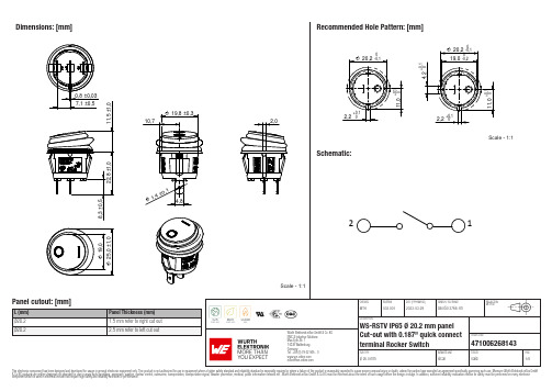
Würth Elektronik eiSos GmbH & Co. KGEMC & Inductive Solutions471006268143 Max-Eyth-Str. 174638 WaldenburgGermanyWürth Elektronik eiSos GmbH & Co. KGEMC & Inductive Solutions471006268143 Max-Eyth-Str. 174638 WaldenburgGermanyWürth Elektronik eiSos GmbH & Co. KGEMC & Inductive Solutions471006268143 Max-Eyth-Str. 174638 WaldenburgGermanyWürth Elektronik eiSos GmbH & Co. KGEMC & Inductive Solutions471006268143 Max-Eyth-Str. 174638 WaldenburgGermanyWürth Elektronik eiSos GmbH & Co. KGEMC & Inductive Solutions471006268143 Max-Eyth-Str. 174638 WaldenburgGermanyCautions and Warnings:The following conditions apply to all goods within the product series of WS-RSTV of Würth Elektronik eiSos GmbH & Co. KG:General:•This mechanical component is designed and manufactured for use in general electronic equipment.•Würth Elektronik must be asked for written approval (following the PPAP procedure) before incorporating the components into any equipment in fields such as military, aerospace, aviation, nuclear control, submarine, transportation (automotive control, train control,ship control), transportation signal, disaster prevention, medical, public information network, etc. where higher safety and reliability are especially required and/or if there is the possibility of direct damage or human injury.•Mechanical components that will be used in safety-critical or high-reliability applications, should be pre-evaluated by the customer. •The component is designed and manufactured to be used within the datasheet specified values. If the usage and operation conditions specified in the datasheet are not met, the component may be damaged or dissolved. •Do not drop or impact the components, the component may flake apart. •Prevent any damage or scratches on the switch, especially on the actuator.•Würth Elektronik products are qualified according to international standards, which are listed in each product reliability report. Würth Elektronik does not warrant any customer qualified product characteristics beyond Würth Elektroniks’ specifications, for its validity and sustainability over time.•The responsibility for the applicability of the customer specific products and use in a particular customer design is always within the authority of the customer. All technical specifications for standard products also apply to customer specific products.Product Specific:Soldering:•The solder profile must comply with the technical product specifications. All other profiles will void the warranty. •Hand soldering max. 350°C for 5 sec max..•All other soldering methods are at the customers’ own risk.•Please keep our switch at delivery original position before and during the soldering process.•Design the right angle part with consideration of the wave soldering process so that the parts will not touch the soldering wave during the soldering process or protect the switch part with cover fixture. Melting of the switch might cause malfunction.Cleaning and Washing:•If a series is washable, the general information section in the datasheet will contain the washability guidelines. Should there be no information regarding washability, the product has not been constructed to withstand a washing process. Washing agents used during the production to clean the customer application might damage or change the characteristics of the component, body, pins and/or termination. Washing agents may have a negative effect on the long-term functionality of the product.If the parts are washable, hermetic:•Cleaning agents that are used to clean the customer applications may damage or change the characteristics of the component, body,pins and termination.•Please do not immerse any washable products into water or cleaning agents or put them in locations exposed to water completely. •Do not clean washable series immediately after soldering. The cleaning agent may be absorbed into the switch through respiration while the switch cools.•Please do not press actuator or change status /position during the cleaning and washing process.•Using a brush during the cleaning process may deform function relevant areas. Therefore, we do not recommend using a brush during the PCB cleaning process.If the parts are not washable:•Parts are not constructed for washing. Washing may cause malfunctions.•When cleaning by hand (brushing), to avoid malfunction, do not use excessive force on switch. Excessive force can deform function relevant areas.Potting and Coating:•If the product is potted in the customer application, the potting material may shrink or expand during and after hardening. Shrinking could lead to an incomplete seal, allowing contaminants into the body, pins or termination. Expansion could damage the components.We recommend a manual inspection after potting or coating to avoid these effectsStorage Conditions:• A storage of Würth Elektronik products for longer than 12 months is not recommended. Within other effects, the terminals may suffer degradation, resulting in bad solderability. Therefore, all products shall be used within the period of 12 months based on the day of shipment.•Do not expose the components into direct sunlight.•The storage conditions in the original packaging are defined according to DIN EN 61760-2.•For a moisture sensitive component, the storage condition in the original packaging is defined according to IPC/JEDEC-J-STD-033. It is also recommended to return the component to the original moisture proof bag and reseal the moisture proof bag again.•The storage conditions stated in the original packaging apply to the storage time and not to the transportation time of the components.Packaging:•The packaging specifications apply only to purchase orders comprising whole packaging units. If the ordered quantity exceeds or islower than the specified packaging unit, packaging in accordance with the packaging specifications cannot be ensured.Würth Elektronik eiSos GmbH & Co. KG EMC & Inductive Solutions Max-Eyth-Str. 174638 Waldenburg GermanyCHECKED REVISION DATE (YYYY-MM-DD)GENERAL TOLERANCEPROJECTION METHODMTH003.0012023-03-29DIN ISO 2768-1mDESCRIPTIONWS-RSTV IP65 Ø 20.2 mm panel Cut-out with 0.187’’ quick connect terminal Rocker SwitchORDER CODE471006268143SIZE/TYPEBUSINESS UNITSTATUSPAGEHandling:Please refer to the pre-caution guide: www.we-online.de/precaution_rockerswitches_1These cautions and warnings comply with the state of the scientific and technical knowledge and are believed to be accurate and reliable.However, no responsibility is assumed for inaccuracies or incompleteness.Würth Elektronik eiSos GmbH & Co. KG EMC & Inductive Solutions Max-Eyth-Str. 174638 Waldenburg GermanyCHECKED REVISION DATE (YYYY-MM-DD)GENERAL TOLERANCEPROJECTION METHODMTH003.0012023-03-29DIN ISO 2768-1mDESCRIPTIONWS-RSTV IP65 Ø 20.2 mm panel Cut-out with 0.187’’ quick connect terminal Rocker SwitchORDER CODE471006268143SIZE/TYPEBUSINESS UNITSTATUSPAGEImportant NotesThe following conditions apply to all goods within the product range of Würth Elektronik eiSos GmbH & Co. KG:1. General Customer ResponsibilitySome goods within the product range of Würth Elektronik eiSos GmbH & Co. KG contain statements regarding general suitability for certain application areas. These statements about suitability are based on our knowledge and experience of typical requirements concerning the areas, serve as general guidance and cannot be estimated as binding statements about the suitability for a customer application. The responsibility for the applicability and use in a particular customer design is always solely within the authority of the customer. Due to this fact it is up to the customer to evaluate, where appropriate to investigate and decide whether the device with the specific product characteristics described in the product specification is valid and suitable for the respective customer application or not.2. Customer Responsibility related to Specific, in particular Safety-Relevant ApplicationsIt has to be clearly pointed out that the possibility of a malfunction of electronic components or failure before the end of the usual lifetime cannot be completely eliminated in the current state of the art, even if the products are operated within the range of the specifications.In certain customer applications requiring a very high level of safety and especially in customer applications in which the malfunction or failure of an electronic component could endanger human life or health it must be ensured by most advanced technological aid of suitable design of the customer application that no injury or damage is caused to third parties in the event of malfunction or failure of an electronic component. Therefore, customer is cautioned to verify that data sheets are current before placing orders. The current data sheets can be downloaded at .3. Best Care and AttentionAny product-specific notes, cautions and warnings must be strictly observed. Any disregard will result in the loss of warranty.4. Customer Support for Product SpecificationsSome products within the product range may contain substances which are subject to restrictions in certain jurisdictions in order to serve specific technical requirements. Necessary information is available on request. In this case the field sales engineer or the internal sales person in charge should be contacted who will be happy to support in this matter.5. Product R&DDue to constant product improvement product specifications may change from time to time. As a standard reporting procedure of the Product Change Notification (PCN) according to the JEDEC-Standard inform about minor and major changes. In case of further queries regarding the PCN, the field sales engineer or the internal sales person in charge should be contacted. The basic responsibility of the customer as per Section 1 and 2 remains unaffected.6. Product Life CycleDue to technical progress and economical evaluation we also reserve the right to discontinue production and delivery of products. As a standard reporting procedure of the Product Termination Notification (PTN) according to the JEDEC-Standard we will inform at an early stage about inevitable product discontinuance. According to this we cannot guarantee that all products within our product range will always be available. Therefore it needs to be verified with the field sales engineer or the internal sales person in charge about the current product availability expectancy before or when the product for application design-in disposal is considered. The approach named above does not apply in the case of individual agreements deviating from the foregoing for customer-specific products.7. Property RightsAll the rights for contractual products produced by Würth Elektronik eiSos GmbH & Co. KG on the basis of ideas, development contracts as well as models or templates that are subject to copyright, patent or commercial protection supplied to the customer will remain with Würth Elektronik eiSos GmbH & Co. KG. Würth Elektronik eiSos GmbH & Co. KG does not warrant or represent that any license, either expressed or implied, is granted under any patent right, copyright, mask work right, or other intellectual property right relating to any combination, application, or process in which Würth Elektronik eiSos GmbH & Co. KG components or services are used.8. General Terms and ConditionsUnless otherwise agreed in individual contracts, all orders are subject to the current version of the “General Terms and Conditions of Würth Elektronik eiSos Group”, last version available at .Würth Elektronik eiSos GmbH & Co. KGEMC & Inductive SolutionsMax-Eyth-Str. 174638 WaldenburgGermanyCHECKED REVISION DATE (YYYY-MM-DD)GENERAL TOLERANCE PROJECTIONMETHODMTH003.0012023-03-29DIN ISO 2768-1mDESCRIPTIONWS-RSTV IP65 Ø 20.2 mm panelCut-out with 0.187’’ quick connectterminal Rocker SwitchORDER CODE471006268143SIZE/TYPE BUSINESS UNIT STATUS PAGE。
常用电力电缆规格型号之欧阳与创编

聚氯乙烯绝缘聚氯乙烯护套电力电缆1、用途:本产品适用于交流50HZ,额定电压0.6/1KV 的线路中,供输配电能之用。
2、产品标准:GB12706·2-91额定电压35KV及以下铜芯、铝芯塑料绝缘电力电缆、聚氯乙烯绝缘电力电缆3、使用特性:1)电缆导体的最高额定温度为70℃。
2)短路时(最长持续时间不超过5S)电缆导体的最高温度不超过160℃。
3)敷设电缆时的环境温度应不低于0℃,最小弯曲半径应不小于电缆外径的10倍。
4、型号、名称和使用范围6、生产范围交联聚乙烯绝缘电力电缆1、产品用途:本产品适用于额定电压(U0/U)为3.6/6至26/35KV电力线路,供输配电能之用。
2、产品标准:GB12706-91额定电压35KV及以下铜芯,铝芯塑料绝缘电力电缆。
3、产品使用特性:(1)电缆在环境温度不低于0℃条件下敷设时,无须预先加温。
电缆的敷设落差不受限制。
(2)电缆线芯长期允许工作温度不得超过下列规定:外护层是聚氯乙烯套的电缆为90℃;外护层是聚乙烯套的电缆为80℃。
(3)线芯短路时(最长持续5S)温度不得超过250℃(4)电缆敷设时的最小弯曲半径规定如下:单芯电缆:20(d+D)±5%;三芯电缆:15(d+D)±5%。
式中:D为电缆的实际外径,d为导体的实际外径。
4、产品型号、名称及使用范围注:一根或二根单芯电缆不允许敷设在铁质管道中。
5、生产范围聚氯乙烯绝缘电线1、用途:本产品适用于交流额定电压450/750V及以下的动力装置的固定敷设。
2、产品标准:GB5023、2-85《额定电压450/750V及以下聚氯乙烯绝缘电缆(电线)固定敷设用电缆(电线)》3、产品使用特性:1)额定电压U0/U分为450/750V 和300/500V。
2)电缆的长期允许工作温度:BV-105型……应不超过105℃;其他型号……应不超过70℃。
3)电缆的敷设温度应不低于0℃;4)电缆的允许弯曲半径为:电缆外径(D)小于25mm者……应不小于4D;电缆外径(D)为25mm及以上者……应不小于6D4、电缆型号、名称及使用范围5、生产范围聚氯乙烯绝缘软电线1、用途:本产品适用于交流额定电压450/750V及以下的家用电器、小型电动工具、仪器仪表及动力照明等装置的连接。
PCR606 可控硅

DIM
Inches (英寸單位)
Millimeter (毫米單位)
Min (最小) Max (最大) Min (最小) Max (最大)
A
0.175 0.205 4.450
5.200
B
0.170 0.210 4.320
5.330
C
0.125 0.165 3.180
4.190
D
0.016 0.021 0.407
2.540
R
0.115
----
2.930
----
V
0.135
----
3.430
----
Web: HAOHAI ELECTRONICS CO., LTD.
KKG@Product Data 2006-08-01
E-mail: kkg@ High Sensitive SCRs PCR_06 Series TO-92
di / dt
通態臨界電流上升率: Critical Rate of Rise of On−State Current
RD Rth(j-c)
通態輸出阻抗: Dynamic resistance slops Resistance 熱阻-結到外殼: Thermal Resistance−Junction−to−Case
0.6A SCR :高靈敏度 - 微觸發單向可控硅【溫度特性】
英文與中文繁體版本
無鉛産品提供SGS環保認證, 符合歐美RoHS環保指令標準
Web: HAOHAI ELECTRONICS CO., LTD.
KKG@Product Data 2006-08-01
Paramenter & Test Conditions 參數符號含義 及 測試條件說明
聚氯乙烯绝缘
点线缆各种规格型号千余种,和同行们共同分享聚氯乙烯绝缘(阻燃)控制电缆产品型号规格范围使用场合KVV,KVVP,KVVP2 0.5-10mm 2 ,2-61 芯适用于弱电控制系统或强电磁场干扰区 KVV22,KVV20 0.5-10mm 2 ,4-61 芯 KVV32,KVV300.5-10mm 2 ,7-61 芯 KVVR 0.5-6mm 2 ,2-61 芯 KVVRP 0.5-4mm 2 ,2-61 芯 KVVP22,KVVP2-22 1.5-10mm 2 ,4-61 芯 KVVP2-22-1 1.5-10mm 2 ,4-61 芯主要用于500KV 变电站与发电厂配电装置及强电磁场干扰区 KVV-1,KVV22-1 0.5-10mm 2 ,2-61 芯注:型号前加“ZR”为阻燃型,适用于火灾易发生的环境。
(更多电线电缆知识:)聚乙烯绝缘(阻燃)控制电缆产品型号规格范围使用场合 KYV,KYVP,KYVP2 0.5-10mm 2 ,2-61 芯此产品绝缘电阻高,防水性能强,较好的耐寒性,适用于弱电控制系统或强电磁场干扰区。
KYV20,KYV22 0.5-10mm 2 ,4-61 芯 FYV30,KYV32 0.5-10mm 2 ,7-61 芯 KYVR 0.5-6mm2,2-61 芯 KYVRP 0.5-4mm2 ,2-61 芯 KYVP22,KYVP2-22 1.5-10mm 2 ,4-61 芯注:型号前加“ZR”为阻燃型,适用于火灾易发生的环境。
(更多电线电缆知识:)交联聚乙烯绝缘控制电缆产品型号规格范围使用场合 KYJV,KYJVP,KYJVP2 0.75-10mm 2 ,2-61 芯具有优良的电气性能,耐化学腐蚀,适用于负载大、环境KYJV22,KYJVP22KYJVP2-22 0.75-10mm 2 ,4-61 芯恶劣的场所。
FYJVR,KYJVRP 0.75-6mm 2 ,2-61 芯 KYJV22-1,KYJVP2-22-10.75-10mm 2 ,7-61 芯主要用于500KV 变电站与发电厂配电装置及强电磁场干扰区。
日博RB600系列变频器使用手册

日博R B600系列变频器使用手册3(总9页)-CAL-FENGHAI.-(YICAI)-Company One1-CAL-本页仅作为文档封面,使用请直接删除3 安装配线3.1 安装环境周围环境应符合下列条件:室内通风良好的场所。
环境温度: -10C~40C,裸机为 -10C~50C 。
防潮:无雨水滴淋,湿度90%(相对)以下。
防晒:避免直接日晒或高温。
无易燃、易爆、腐蚀性气体和液体。
无灰尘、飘浮性的纤维及金属微粒。
无电磁干扰,远离干扰源。
海拔高度1000m 以下。
3.2机械安装➢变频器应安装在平坦表面上,处于垂直位置,其四周应留出如图3-1所示空间:2➢变频器运行时要产生热量,产生的热量向上散发,所以不要安装在不耐热设备的下方。
➢变频器背板与散热器接触较近,散热温度可以达到将近90℃,所以应安装在能耐受较高温度的材质上。
➢变频器安装在控制柜内时,要考虑通风散热,保证变频器周围温度不超过规定值,不要将变频器安装在通风散热不良的密闭箱体中。
➢变频器安装好后,必须盖好外盖,防止各种纤维、纸片、金属碎片等异物进入变频器内部或粘贴于散热片上。
33.3电气安装该系列变频器的电气安装总图示例如图3-2:RST交流电机➢输入电源相数、电压应与变频器铭牌规定的电源相数和额定电压值相符,并且只能接在R、S、T端子上。
➢在变频器的电源侧,需配备电路保护用断路器或带漏电保护的断路器。
否则可能发生火警。
➢变频器输出端子U、V、W应按相序接至三相电动机,如电动机旋转反向不对,可交换U、V、W中任意两相的接线。
4➢在变频器U、V、W输出端不可加装进相电容或阻容吸收装置;在变频器与电机之间不可加装电磁接触器。
➢输出端子U、V、W绝对不可接至交流电源,否则可能造成设备损坏。
➢变频器接通电源时,即使处于停止状态,变频器端子仍带电,不能接触。
拆换电机时,应先切断变频器输入电源。
必须在确认电源断开后,方可切换电机或进行工频电源的切换。
额定电压10kV及以下架空绝缘电缆参数

3、 敷设环境温度 电缆敷设时的环境温度应不低于-20。 Installation ambient temperature The installation ambient temperature should not below -20℃。
Stranded aluminium conductor steel-reinforced cores aerial insulated cables of rated voltages up to 10 kV ,This product is applicable to the aerial power distribution lines of A.C. voltage up to 10kV.
The aerial insulated cables rated voltage 10kV can be applicable to the system whose single-phase earth fault will be less than 1min/time. And the cable can be also used in the system whose maximum single-phase earth fault will less than 8h/time and total earth-fault time of 1 year won't be above 125 hours. 6、 电缆运输和保管要求 电缆盘不允许平放。 运输中严禁从高处扔下装有电缆的电缆盘,严禁机械损伤电缆。 电缆如果需要分段使用,电缆分段后必须用防水封帽将电缆头密封,防止进水。 The requirements on transportation and storage: The cable reels shall not be delivered and stored in flat state. It is strictly forbidden to push the cable reel from the high level in order to prevent the cable from damages If the cable should be used section ally, the head of the cable must be sealed in order to prevent water intake.
日博RB600系列变频器使用手册7

⏹什么是电磁兼容(EMC)?我国最近颁布的“电磁兼容性”国家标准中,对电磁兼容性的定义是:“设备或系统在其电磁环境中能正常工作且不对该环境中的任何事物构成不能承受的电磁干扰”。
即电磁兼容性包含抗干扰性和干扰性双重含义。
⏹为什么要重视电磁兼容?变频器大多运行在恶劣的电磁环境,作为电力电子设备,其内部由电子元器件、微处理芯片等组成,容易受到外界的电磁干扰。
为了保证系统内每一单元、组件、部件不因电磁干扰而误动作或性能下降,必须注意抗干扰设计。
同时,变频器的输入和输出侧的电压、电流含有丰富的高次谐波,当变频器运行时,可能会干扰其他外界设备。
故在变频器的设计与应用中,还必须考虑变频器干扰性,抑制其对外部设备的干扰,使各种设备协调地共同工作。
⏹电磁兼容标准的内容电磁兼容标准干扰发射敏感度传导辐射电源线信号/控制线天线端口电源线/信号线传导辐射电场磁场射频瞬态天线端口电场磁场静电放电图7-1电磁兼容标准的内容⏹变频器电磁兼容工程方法变频器在电路设计、结构设计、软件设计和工程应用中,可按照电磁兼容工程方法,充分利用屏蔽、滤波、接地、冗余等关键技术,使系统的电路结构和性能日趋合理,抑制外部对变频器的高频和低频干扰,并降低变频器对外部设备的干扰。
图7-2电磁兼容工程方法7.1电路设计伴随着功能的升级,电子电路设计日益复杂,调试也越来越难。
变频器在主电路部分,采用浪涌吸收电容降低了接触器在开、关时产生的干扰脉冲;采用压敏电阻,铁氧体磁环等限制了主电路输入端的尖峰电压;在主电路部分,它采用金属排,扁平电缆,有效减小了高频时对地阻抗。
对于IGBT 模块,为了有效抑制快速关断时的尖峰电压,本变频器采用了IGBT缓冲电路(如图7-3所示)。
因而本变频器具有很强的适应性。
在控制电路部分,本系列变频器主要对核心电路,如PCB控制板等,采用了四层布线技术(如图7-4所示),控制电源和控制地各占一层,主要信号线汇集在板中央,尽量缩小信号线与信号回路线所形成的环路面积。
弱电电线各种参数全解
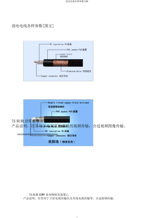
弱电电线各样参数[图文]75欧姆SYV系列实芯聚乙烯绝缘产品说明:往常用于电视监控系统的视频传输,合适视频图像传输。
============================75欧姆SYWV系列物剪发泡聚乙产品说明:往常用于卫星电视传输以及有线电视传输等,合适射频传输。
===============================RG-58--96#-镀锡铜编织-50欧产品说明:往常用于弱电视频图像传输或HFC网络等。
===========================AVVR或RVV护套线产品说明:往常用于弱电电源供电等。
====================AVVR或RVV圆形双绞护套线产品说明:往常用于弱电电源供电等。
=========================扁型无护套软电线或电缆AVRB产品说明:往常用于背景音乐和公共广播,也可做弱电供电电源线。
============================绞型双芯电源线(AVRS或RVS)产品说明:往常用于公共广播系统/背景音乐系统布线,消防系统布线。
============================金银线(也叫:音箱线)产品说明:用于功放机输出至音箱的接线。
====================铜芯聚氯乙烯绝缘安装用电缆产品说明:用于弱电供电电源线,一般合适做供电电流较大的骨干电源供电。
=======================铜芯聚氯乙烯绝缘聚氯乙烯护套线产品说明:往常用于弱电系统中供电电源线。
===========================铜芯聚氯乙烯绝缘障蔽聚氯乙产品说明:带障蔽形,往常用于弱电信号控制及信号传输,可防备扰乱。
有多芯可供选择,比如:RVVP2*线径,RVVP3*线径,RVVP5*线径......======================网线、网络线产品说明:计算机网络线,有5类,6类之分,有障蔽与不障蔽之分。
2206介绍
爱立信RBS2206型基站介绍 爱立信RBS2206型基站介绍 RBS2206
CDU-F CDU-G
解决容量和覆盖的宽带合路器
新硬件单元
高容量基站使用的滤波合路器
CXU
软件控制的接收交换配置单元
dTRU
2 TRX 的收发信单元
DXU21
基于核心基站网络的新型分配交换单元
PSU
新型供电 单元
4
爱立信RBS2206型基站介绍 爱立信RBS2206型基站介绍 RBS2206
3x4
1x12
2206
CDU-G CDU-G CDU-G
2206
CDU-G CDU-G
DTRU DTRU DTRU DTRU DTRU DTRU
DTRU DTRU DTRU DTRU DTRU DTRU
2206
CDU-G CDU-G
DTRU DTRU DTRU DTRU DTRU DTRU
2x12
CDU-G
18
DTRU CDU-G
1x2
2206
2 扇区 1 扇区
DTRU CDU-G
2x2
2206
DTRU CDU-G
3 扇区
DTRU DTRU CDU-G
1x4
2206
RBS 2206 使用 CDU-G
CDU-G
DTRU DTRU DTRU DTRU
爱立信RBS2206型基站介绍 爱立信RBS2206型基站介绍 RBS2206
9
爱立信RBS2206型基站介绍 爱立信RBS2206型基站介绍 RBS2206
CDU-G
10
爱立信RBS2206型基站介绍 爱立信RBS2206型基站介绍 RBS2206
RBV5006中文资料

UPDATE : AUGUST 3, 1998
元器件交易网
RATING AND CHARACTERISTIC CURVES ( RBV5000 - RBV5010 )
AVERAGE FORWARD OUTPUT CURRENT AMPERES
FIG.1 - DERATING CURVE FOR OUTPUT RECTIFIED CURRENT
SILICON BRIDGE RECTIFIERS
RBV25
C3 30 ± 0.3 3.9 ± 0.2 4.9 ± 0.2 ∅ 3.2 ± 0.1 20 ± 0.3
+
13.5 ± 0.3
~ ~
11 ± 0.2
1.0 ± 0.1
MECHANICAL DATA :
* Case : Reliable low cost construction utilizing molded plastic technique * Epoxy : UL94V-O rate flame retardant * Terminals : Plated lead solderable per MIL-STD-202, Method 208 guaranteed * Polarity : Polarity symbols marked on case * Mounting position : Any * Weight : 7.7 grams
100
8.3 ms SINGLE HALF SINE WAVE JEDEC METHOD
0 1 2 4 6 10 20 40 60 100
CASE TEMPERATURE, ( °C)
NUMBER OF CYCLES AT 60Hz
北星(NorthStar)浴室洁净器杆,型号为55775和55776说明书

Telescoping Pressure Washer Wand6'-18' & 6'-24'Owner’s ManualWARNING: Read carefully and understand all ASSEMBLY AND OPERATION INSTRUCTIONS before operating. Failure to follow the safety rules and other basic safety precautions may result in serious personal injury.Item #55775 & #55776Thank you very much for choosing a NorthStar™ product!For future reference, please complete the owner’s record below:Serial Number/Lot Date Code: ________________________________ Purchase Date: ____________________________________________ Save the receipt, warranty, and this manual. It is important that you read the entire manual to become familiar with this product before you begin using it.This pressure wash wand is designed for certain applications only. Northern Tool and Equipment is not responsible for issues arising from modification or improper use of this product such as an application for which it was not designed. We strongly recommend that this product not be modified and/or used for any application other than that for which it was designed.For technical questions, please call 1-800-222-5381.Intended Use (4)Packaging Contents (4)Technical Specifications (4)Important Safety Information (4)Specific Operation Warnings (6)Main Parts of Wand (6)Assembly Instructions (6)Before Each Use (7)Operating Instructions (7)After Each Use (8)Maintenance (9)Troubleshooting (9)Parts Diagram (10)Pole Parts List (10)Gun Parts List (11)Replacement Parts (11)Limited Warranty (12)The NorthStar Telescoping Pressure Washer Wand is a heavy-duty, screw extension clamping system that positions the extension pole at the desired length for cleaning. The high-flow spray gun allows for low pressure chemical applications and is firmly secured to the exterior fiberglass pole. The gun inlet is 3/8" NPT-F and also provides a 1/4" Q/C male plug X M22 male screw type brass fitting. The nozzle holder accepts standard quick couple-spray nozzles (nozzles not included).For Item #55775: One 6'-18' telescoping wand complete with assembled gunFor Item #55776: One 6'-24' telescoping wand complete with assembled gunTo protect the coupler and lance during shipping, these parts are shipped strapped to the extension pole. All giraffe wands require some final assembly. To complete the assembly, simply attach the M22 fitting as illustrated.The wand is now ready for use.∙Read, understand, and follow ALL safety guidelines and operation instructions prior to use.∙Do NOT bypass, disable, or remove the trigger gun.∙DO NOT use pliers, pipe wrenches, etc., to tighten as it will cause the collet to seize to the threaded plastic housing. HAND TIGHTEN ONLY!To Use the WandConnect the outlet of your pressure washer to the inlet port of the trigger gun of the giraffe extension wand using appropriate quick couplers or fittings rated to handle high pressure.The giraffe extension wand may be used fully retracted or fully extended or any point in between.To Extend the WandLoosen the lock rings and pull the wand out to the desired length. Re-tighten the lock rings to hold the wand at the desired length.To Retract the WandLoosen the lock rings and slide the extension segment into the wand until the desired length is reached and re-tighten the lock rings to hold the extension segments in place.To Begin SprayingStart the pressure washer. Raise the wand and keep the nozzle at least ten feet away from the surface to be cleaned. Squeeze the trigger to begin spraying, maintain stable footing, and move the wand in to the surface to be cleaned.To Stop Spraying:Before releasing the trigger gun move the nozzle at least ten feet away from the surface being cleaned and make sure you have solid footing. The wand will rebound when the trigger is released or if pressure is lost. When you are clear of the work surface and in a safe area - release the trigger.Clear the wand of water, fully retract, and store in safe place.Maintain the product by adopting a program of conscientious repair and maintenance. It is recommended that the general condition of any tool be examined before it is used. Keep your wand in good repair. Keep handles dry, clean, and free from oil and grease.Use the table below to troubleshoot problems before contacting service personnel or your local dealer. If the problem continues after troubleshooting, call your local dealer for assistance.∙For replacement parts and technical questions, please call Customer Service at 1-800-222-5381. ∙Not all product components are available for replacement. The illustrations provided are a convenient reference to the location and position of parts in the assembly sequence.∙When ordering parts, the following information will be required: item description, item model number, item serial number/item lot date code, and the replacement part reference number.∙The distributor reserves the rights to make design changes and improvements to product lines and manuals without notice.Northern Tool and Equipment Company, Inc. ("We'' or "Us'') warrants to the original purchaser only ("You'' or "Your") that the NorthStar product purchased will be free from material defects in both materials and workmanship, normal wear and tear excepted, for a period of two years from date of purchase. The foregoing warranty is valid only if the installation and use of the product is strictly in accordance with product instructions. There are no other warranties, express or implied, including the warranty of merchantability or fitness for a particular purpose. If the product does not comply with this limited warranty, Your sole and exclusive remedy is that We will, at our sole option and within a commercially reasonable time, either replace the product or product component without charge to You or refund the purchase price (less shipping). This limited warranty is not transferable.Limitations on the WarrantyThis limited warranty does not cover: (a) normal wear and tear; (b) damage through abuse, neglect, misuse, or as a result of any accident or in any other manner; (c) damage from misapplication, overloading, or improper installation; (d) improper maintenance and repair; and (e) product alteration in any manner by anyone other than Us, with the sole exception of alterations made pursuant to product instructions and in a workmanlike manner.Obligations of PurchaserYou must retain Your product purchase receipt to verify date of purchase and that You are the original purchaser. To make a warranty claim, contact Us at 1-800-222-5381, identify the product by make and model number, and follow the claim instructions that will be provided. The product and the purchase receipt must be provided to Us in order to process Your warranty claim. Any returned product that is replaced or refunded by Us becomes our property. You will be responsible for return shipping costs or costs related to Your return visit to a retail store.Remedy LimitsProduct replacement or a refund of the purchase price is Your sole remedy under this limited warranty or any other warranty related to the product. We shall not be liable for: service or labor charges or damage to Your property incurred in removing or replacing the product; any damages, including, without limitation, damages to tangible personal property or personal injury, related to Your improper use, installation, or maintenance of the product or product component; or any indirect, incidental or consequential damages of any kind for any reason.Assumption of RiskYou acknowledge and agree that any use of the product for any purpose other than the specifieduse(s) stated in the product instructions is at Your own risk.Governing LawThis limited warranty gives You specific legal rights, and You also may have other rights which vary from state to state. Some states do not allow limitations or exclusions on implied warranties or incidental or consequential damages, so the above limitations may not apply to You. This limited warranty is governed by the laws of the State of Minnesota, without regard to rules pertaining to conflicts of law. The state courts located in Dakota County, Minnesota shall have exclusive jurisdiction for any disputes relating to this warranty.Distributed by:Northern Tool & Equipment Company, Inc.Burnsville, Minnesota 55306Made in China。
黑芯BF609嵌入式视觉开发者套件说明书

Starter Kit Features
Functions/Features Low cost Easy to use out-of-box demo Small form factor USB powered 720p color image sensor with graphics overlay at 30fps HDMI video output Reference design showing operation of both Blackfin cores and video accelerators Demonstrate BF609 hardware subsystem advantages
Target Markets Assistance for the vision impaired Bar code scanning Building automation Digital signage Gesture recognition Machine vision Military Medical Robot vision Safety monitoring Security camera analytics Traffic monitoring Thermal imaging cameras
Blackfin BF609 Embedded Vision Starter Kit
BF609 Embedded Vision Starter Kit
An Avnet exclusive, low-cost kit with reference designs to quickly evaluate the processing capabilities of the Analog Devices dual-core Blackfin BF609 for embedded vision applications
RB600系列变频器说明书
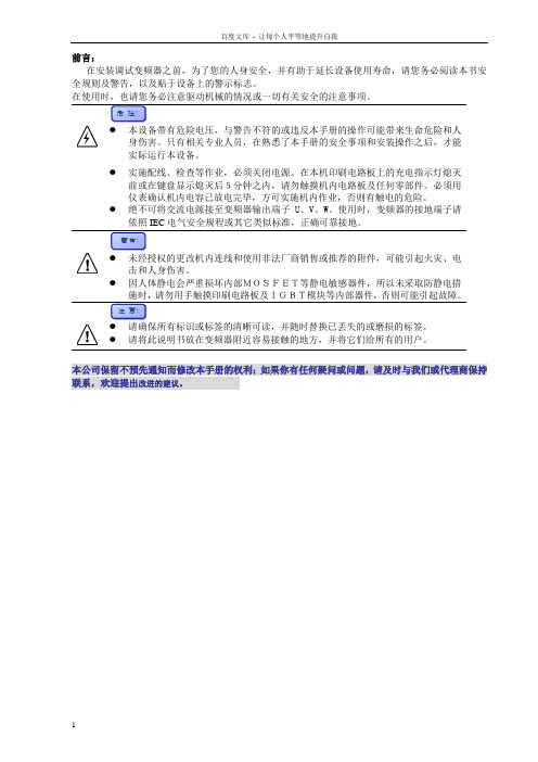
在安装调试变频器之前,为了您的人身安全,并有助于延长设备使用寿命,请您务必阅读本书安全规则及警告,以及贴于设备上的警示标志。
实际运行本设备。
●实施配线、检查等作业,必须关闭电源。
在本机印刷电路板上的充电指示灯熄灭前或在键盘显示熄灭后5分钟之内,请勿触摸机内电路板及任何零部件。
必须用仪表确认机内电容已放电完毕,方可实施机内作业,否则有触电的危险。
●绝不可将交流电源接至变频器输出端子U、V、W。
使用时,变频器的接地端子请依照IEC电气安全规程或其它类似标准,正确可靠接地。
●因人体静电会严重损坏内部MOSFET等静电敏感器件,所以未采取防静电措●请将此说明书放在变频器附近容易接触的地方,并将它们给所有的用户。
本公司保留不预先通知而修改本手册的权利;如果你有任何疑问或问题,请及时与我们或代理商保持联系,欢迎提出改进的建议。
1 产品简介…………………………………………………………1-1RB600 …………………………………………………………1-1储存运输………………………………………………………1-3开箱检查………………………………………………………1-32 技术规范…………………………………………………………2-1规格尺寸………………………………………………………2-1技术规范………………………………………………………2-33 安装配线…………………………………………………………3-1安装环境………………………………………………………3-1机械安装………………………………………………………3-1电气安装………………………………………………………3-24 操作运行…………………………………………………………4-1键盘操作………………………………………………………4-1参数修改………………………………………………………4-3参数监视………………………………………………………4-5初步运行………………………………………………………4-55 功能参数…………………………………………………………5-1功能简表………………………………………………………5-1详细功能………………………………………………………5-96 故障排除…………………………………………………………6-1故障查询………………………………………………………6-1故障代码………………………………………………………6-2异常处理………………………………………………………6-37 电磁兼容…………………………………………………………7-18 选件/附件………………………………………………………8-19 应用实例…………………………………………………………9-110保养维护…………………………………………………………10-1附录一:RS485串行通讯协议附录二:名词索引RB600是用于控制三相交流电动机的变频调速器。
- 1、下载文档前请自行甄别文档内容的完整性,平台不提供额外的编辑、内容补充、找答案等附加服务。
- 2、"仅部分预览"的文档,不可在线预览部分如存在完整性等问题,可反馈申请退款(可完整预览的文档不适用该条件!)。
- 3、如文档侵犯您的权益,请联系客服反馈,我们会尽快为您处理(人工客服工作时间:9:00-18:30)。
UNIT Volts Volts Volts Amps. Amps. A2S Volts µA µA °C/W °C °C
VRRM VRMS VDC IF(AV) IFSM It VF IR IR(H) RθJC TJ TSTG
2
200 64 1.0 10 200 8.0 - 40 to + 150 - 40 to + 150
6.0
FIG.2 - MAXIMUM NON-REPETITIVE PEAK FORWARD SURGE CURRENT
240
5.0
200
4.0
160
TJ = 50 °C
3.0
120
2.0
80
1.0
HEAT-SINK MOUNTING, Tc 2.6" x 1.4" x 0.06" THK. (6.5cm x 3.5cm x 0.15cm) Al.-PLATE 0 25 50 75 100 125 150 175
元器件交易网
RBV600 - RBV610
PRV : 50 - 1000 Volts Io : 6.0 Amperes
FEATURES :
* * * * * * * * High current capability High surge current capability High reliability Low reverse current Low forward voltage drop High case dielectric strength of 2000 VDC Ideal for printed circuit board Very good heat dissipation
MAXIMUM RATINGS AND ELECTRICAL CHARACTERISTICS
RATING
Maximum Recurrent Peak Reverse Voltage Maximum RMS Voltage Maximum DC Blocking Voltage Maximum Average Forward Current Tc = 55°C Peak Forward Surge Current Single half sine wave Superimposed on rated load (JEDEC Method) Current Squared Time at t < 8.3 ms. Maximum Forward Voltage per Diode at IF = 3.0 Amps. Maximum DC Reverse Current at Rated DC Blocking Voltage Ta = 25 °C Ta = 100 °C
10 7.5 7.5 2.0 ± 0.2 0.7 ± 0.1 ±0.2 ±0.2 ±0.2
Dimensions in millimeters
Rating at 25 °C ambient temperature unless otherwise specified. Single phase, half wave, 60 Hz, resistive or inductive load. For capacitive load, derate current by 20%.
UPDATE : MARCH 6, 2000
元器件交易网
RATING AND CHARACTERISTIC CURVES ( RBV600 - RBV610 )
AVERAGE FORWARD OUTPUT CURRENT, AMPERES
FIG.1 - DERATING CURVE FOR OUTPUT RECTIFIED CURRENT PEAK FORWARD SURGE CURRENT, AMPERES
100
FIG.4 - TYPICAL REVERSE CHARACTERISTICS PER DIODE
10
FORWARD CURRENT, AMPERES
REVERSE CURRENT, MICROAMPERES
TJ = 100 °C
10
1.0
1.0
Pulse Width = 300 µs 1 % Duty Cycle
Typical Thermal Resistance (Note 1) Operating Junction Temperature Range Storage Temperature Range
Notes : 1. Thermal Resistance from junction to case w ith units mounted on a 2.6"x1.4"x0.06" THK (6.5cm.x3.5cm.x0.15cm.) Al. Plate. Heatsink.
SILICON BRIDGE RECTIFIERS
RBV25
3.9 ± 0.2 C3 30 ± 0.3 4.9 ± 0.2 ∅ 3.2 ± 0.1 20 ± 0.3
+
13.5 ± 0.3
~ ~
11 ± 0.2
1.0 ± 0.1
MECHANICAL DATA :
* Case : Reliable low cost construction utilizing molded plastic technique * Epoxy : UL94V-O rate flame retardant * Terminals : Plated lead solderable per MIL-STD-202, Method 208 guaranteed * Polarity : Polarity symbols marked on case * Mounting position : Any * Weight : 7.7 grams
0.1
TJ = 25 °C
TJ = 25 °C
0.1 0.01 0 20 40 60 80 100 120 140
PERCENT OF RATED REVERSE VOLTAGE, (%)
0.01 0.4 0.6 0.8 1.0 1.2 1.4 1.6 1.8
FORWARD VOLTAGE, VOLTS
40
8.3 ms SINGLE HALF SINE WAVE JEDEC METHOD
0
0 1 2 4 6 10 20 40 60 100
CASE TEMPERATURE, ( °C)
NUMBER OF CYCLES AT 60Hz
FIG.3 - TYPICAL FORWARD CHARACTERISTICS PER DIODE
SYMBOL
RBV 600 50 35 50
RBV 601 100 70 100
RBV 602 200 140 200
RBV 604 400 280 400 6.0
RBV 606 600 420 600
17.5 ± 0.5
RBV 608 800 560 800
RBV 610 1000 700 1000
