BD6020GU中文资料
铅酸蓄电池产品介绍(品牌)

淄博火炬PzS系列牵引蓄电池电动车电池系列起动用铅酸蓄电池产品介绍公司研制生产的起动用铅酸蓄电池有全系列普通干荷电型和常用密闭免维护型,产品执行GB5008.1-2005及GB/T728-2000标准。
船用蓄电池产品通过了中国船级社和中国渔业船舶检验局的型式认可。
产品用途适用于各种汽车、拖拉机、船舶和海上平台的内燃机起动、点火和照明。
产品特性具有容量足、寿命长,低温起动性能可靠、耐震动性好、水损耗低等特点。
起动用铅酸蓄电池产品规格及基本参数表1 塑壳干荷电铅酸蓄电池6V/12V阀控式密封铅酸蓄电池产品介绍产品性能执行YD/T799-2002及GB /T3821-2000标准。
船用产品(CTM)系列通过了中国船级社的型式认可。
产品用途适用于UPS、风力和太阳能发电贮存、电话交换机、船舶通讯照明、电站及其他需要直流电源的场所。
产品特性板栅采用优质高锡低钙四元合金,降低了电池的内阻,改善了电池的深循环性能和使用寿命,具有电压一致性好、气体复合效率高、自放电低、密封可靠等特点。
表 3 6V/12V阀控式密封铅酸蓄电池规格及参数电动车用铅酸蓄电池产品介绍公司研制生产的电动车用铅酸蓄电池有管式蓄电池和板式蓄电池两种,产品性能符合GB/T7403.1-1996标准。
产品用途适用于高尔夫球车、电动游览车、电动巡逻车、电动三轮车,作为配套的动力直流电源。
产品特性管式蓄电池即正极板为管式,负极板为涂膏式,正板栅采用高锑多元合金,提高了电池的深循环性能和电池的使用寿命。
板式蓄电池即正负极板都是涂膏式,具有以下特点:1、板栅采用低锑七元合金,板栅副食和水损耗显著降低;2、采用过外先进技术,提高了活性物质和板栅的结合强度,延长了极板的使用寿命。
防爆系列OPzS系列GGM(OPzS)固定用新型富液式铅酸蓄电池系列是按照德国标准研制开发的一种高性能、长寿命全新产品,20℃条件下浮充运行使用寿命保证达到15年以上。
产品从200Ah-3000Ah共14个规格。
共立6020中文使用说明书
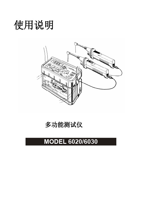
使用说明多功能测试仪MODEL 6020/6030目录1. 安全警告2. 特点3. 规格4. 仪器布局5. 测试前准备工作6. 测量方法6.1 AC电压测量6.2 绝缘电阻测量6.3. 接地电阻测量6.4. 相位测量6.5. 照明6.6. 导线卷轴6.7. 自动关机6.8. 使用肩带7. 电池更换8.要求维修服务前的注意事项z设计符合安全规格IEC 1010,过电压 CAT II。
z本说明书包括警告和安全规格,必须严格遵守以确保安全操作。
因此,使用前请务必通读操作指示。
z仪器上的标志提醒用户必须遵守说明书中相关指示以确保仪器安全操作。
z请务必注意仪器上的所有警告和注意事项。
警告事项提醒用户避免触电事故,注意事项避免仪器损害。
1.测量前请确保量程开关调节在适当位置。
2.请务必确保测试线完全插入仪器端口。
3.仪器潮湿时请勿连接测试线。
4.测量时的输入值请勿超量程范围。
5.测试线连接被测回路时请勿切换量程。
6.请确认仪器和接地间的对地电压低于600V。
7.请勿在易燃环境中测量。
(例:易燃性气体或火花、蒸气、灰尘处)可能会引起爆炸。
8.每次使用前请检查仪器、测试线、附件等是否存在危险或异常现象。
若存在异常情况(例:测试线断裂,仪器外壳龟裂)请勿测量。
9.打开电池盖更换电池时请确认已关闭电源并取下测试线。
10.仪器潮湿时请勿更换电池。
11.使用后请关闭电源。
12.请勿将仪器暴露在阳光直射、潮湿及高温环境中。
13.请勿在50℃以上环境中使用。
14.必须由专业工程师对仪器进行校准和修理。
除非有其他能进行急修的人员在现场,否则请勿尝试校准或修理。
15.请勿随意更换仪器部件。
为确保仪器安全请将仪器返还销售商或修理中心维修。
16.必须由专业人员严格按照指示操作。
对任何因错误使用或未遵守指示造成的仪器损害和人身事故,共立公司概不负责。
因此,请通读并理解说明书中内容并在使用时严格遵守。
MODEL 6020/6030是一台全天候型多功能测试仪,可进行额定电压600V AC/DC的配电系统或电气设备的测量和维护。
德恩科电机BG系列无刷直流电机产品说明书
D I NE N I S O9001:2000D I N EN I S O 14001Foreword / 前言To Our Valued Customers,Alcatel-Lucent Dunkermotoren is a world class leader in high quality motion control solutions to meet the ever increasing demands for cost effective and reliable drive solutions.Our comprehensive product range offers the flexibilityto provide customized solutions as well as standardized components.The catalog represents Dunkermotoren´s years of engineering excellence.The Dunkermotoren Team will continue to utilize our outstanding engineering and industrial capabilities to meet the requirements helping you to succeed.Wishing you great success in your business.Nikolaus GräfGeneral Manager 致我们尊敬的客户,阿尔卡特-朗讯旗下的德恩科电机是世界一流的运动控制领域的领先制造商,它提供的优质的传动控制解决方案,满足了客户对成本和可靠性日益增长的的需求。
我们的产品范围包括各种类型的产品,因此具有灵活性;除了提供标准化的部件,还提供用户化的解决方案。
SLA6020中文资料

(VCE=–4V)
hFE
hFE
1000 500
= Ta
C 5° 12
Ta
75°C 25°C
75°C
–3 C 0°
1000 500
25°C
–
° 30
C
100 50 30 0.02
100 50 30 –0.03 –0.05
0.05
0.1
0.5
1
5
8
–0.1
–0.5
–1
–5
–8
IC (A)
–0.5
–1
–5
–8
0 0
–1
–30°C
100
100
Ta=1
25°C 75°C 25°C
–2
–2
–3
IC (A)
IC (A)
VBE (V)
hFE-IC Temperature Characteristics (Typical)
NPN
20000 10000 5000
PNP
(VCE=4V)
20000 10000 5000
–500
2
–2
IC=–5A IC=–3A
5
IC=5A IC=3A
1
IC=1A
–1
IC=–1A
1
0 0.2
0.5
1
5
10
50
0 –0.2
0.5
–0.5 –1
–5 –10
–50 –100
IB (mA)
1
5
10
50
100
500 1000
IB (mA)
PW (mS)
VCE(sat)-IC Temperature Characteristics (Typical)
bd62011中文规格书

bd62011中文规格书BD62011中文规格书在BD62011中文规格书中,我们将详细介绍该产品的规格和功能。
BD62011是一款功能强大的设备,适用于各种应用场景。
以下是对该产品规格书的详细解读。
1. 产品介绍BD62011是一款高性能的电子设备,采用先进的技术和设计。
该产品具有多种功能,适用于各种领域,包括工业控制、通信设备和汽车电子等。
2. 主要特性BD62011具有以下主要特性:- 高性能处理器:搭载了先进的处理器,能够快速处理大量数据和复杂计算。
- 多种接口:支持多种接口,包括USB、HDMI、以太网等,方便与其他设备进行连接和通信。
- 大容量存储:内置大容量存储器,能够存储大量数据和文件。
- 高清显示:支持高清显示,显示效果清晰、细腻。
- 多功能操作:支持多种操作模式,包括触摸屏、语音识别和手势控制等。
3. 规格参数- 处理器:采用X1处理器,主频2.4GHz,四核心。
- 存储器:内置8GB闪存和2GB内存。
- 显示屏:5.5英寸高清触摸屏,分辨率为1920x1080。
- 操作系统:基于Android 9.0开发的操作系统。
- 电池容量:3000mAh锂电池,可支持长时间使用。
- 尺寸和重量:151x75x8.1mm,重量约为180g。
4. 功能介绍- 多媒体功能:支持多种媒体格式的播放,包括音乐、视频和图片等。
- 网络通信:支持4G网络通信,能够快速上网和进行在线交流。
- 导航定位:内置GPS芯片,支持导航定位功能,能够准确导航。
- 传感器:内置多种传感器,包括重力感应器、陀螺仪和指纹识别等。
- 扩展接口:支持扩展接口,包括SD卡插槽和耳机接口等。
5. 应用场景BD62011适用于多种应用场景,包括:- 工业控制:可用于工业自动化控制系统,提供可靠的控制和监测功能。
- 通信设备:可用于通信基站、路由器等设备,提供稳定的通信连接和数据传输。
- 汽车电子:可用于汽车导航、娱乐系统等,提供高清显示和多媒体功能。
Philips Laser MFD 6020 激光多功能一体机说明书

LaserMFD 6020LFF6020简化您的日常工作全新飞利浦激光 MFD 6020 将多个办公室日常工作揽于一身 - 传真、打印、扫描和复印。
激光技术节省了多达 40% 碳粉,而环保模式可确保能源效率。
方便易用的复印机99 张多张复印缩放 25-400%彩色扫描仪光学分辨率 600 x 2400 dpi环保模式确保能源效率舒适的能源管理节省多达 40% 碳粉高效能激光打印机250 页大容量进纸托盘,避免供纸中断每分钟最多打印 20 页。
灵活的直插式 USB从 USB 记忆棒直接打印直接扫描到 USB 记忆棒带扫描和复印功能的激光打印机LFF6020/CNB规格产品亮点打印机打印分辨率: 600 x 600 dpi打印速度: 20 ppm手动双面打印进纸托盘: 多达 250 页扫描仪分辨率: 4800 x 4800光学分辨率: 600 x 2400 dpi复印机灰阶: 64缩放功能(放大/缩小)多张复印: 多达 99 页复制分辨率:: 600 x 600 dpi复制速度: 20 ppm身份证复制功能直插式 USB可移动存储器打印(U 盘)扫描到可移动存储器(U 盘)电脑连接电脑接口 USB 2.0WLAN-dongle: 可选附件飞利浦 PFA 820: 带 PLUG'N'PRINT 卡的墨盒插电使用待机: 13 瓦节能模式: 10 瓦工作: 340 瓦尺寸带包装(宽x高x厚): 450x487x524 毫米不带包装: 344x447x386 毫米重量带包装(含国家套件): 14.5 千克不带包装(不含附件): 11.6 千克温度范围工作: 10°C 至 32°C带包装存放: -20°C 至 40°C相对湿度工作: 20% 至 80%带包装存放: 20% 至 80%标准包装包括CD: 2(含手册)设备: 含电源线简易安装入门碳粉盒保修信息操作系统LinuxMac OS X: 10.3 至 10.5Vista x32Windows 2000 (>SP4)Windows XP (>SP1)x64 和 Windows Server 2003: 仅限于打印处理器对于 Windows 2000 系统: 800 MHz对于 Windows Vista 和 XP 系统: 1 GHzRAM对于 Windows 2000 系统: 128 MB对于 Windows Vista 系统: 1 GB对于 Windows XP: 192 MB功能打印方法: 激光多功能产品99 张多张复印99 张多张复印250 页大容量进纸托盘250 页大容量进纸托盘,避免供纸中断舒适的能源管理舒适的能源管理从 USB 记忆棒直接打印从 USB 记忆棒直接打印直接扫描到 USB 记忆棒直接扫描到 USB 记忆棒光学分辨率光学分辨率 600 x 2400 dpi每分钟最多打印 20 页。
DP6020低压差分探头 (20V 200MHz)

DP6020低压差分探头(20V/200MHz)DP6020探头是具有浮地测量功能的低压差分探头。
在各种应用中得到广泛使用,可以为当今的高速功率测量、车载总线测量和数字系统设计提供出色的通用差分信号测量。
一、概述1DP6020探头是具有浮地测量功能的低压差分探头;2测量电压±20V(DC+Pk),其带宽最高达200MHz;3提供10:1的衰减设置,具有1MΩ的输入阻抗,以及 3.5pF的低输入电容,可以最大程度地降低电路负载;4具有过压报警功能,可以兼容任何具有50ΩBNC输入的示波器;5可以通过示波器或计算机上的USB端口供电。
6在各种应用中得到广泛使用,可以为当今的高速功率测量、车载总线测量和数字系统设计提供出色的通用差分信号测量。
二、DP6020简要说明型号最大输入差动电压带宽衰减比DP602020V200MHz10X三、产品细节说明■探头主体说明详细说明:1输入线:长度约15cm,连接探夹后测量电压信号。
2偏置调节:调节该可调电阻,实现输出偏置调节。
3连接线:探头前端和后端连接线,长度70cm4电源接口:标准的USB B型接口,通过标配的USB适配器供电;也可以通过示波器供电,使用方便。
5过载报警指示灯(Overload):测量范围超过量程时,过载指示灯亮,且发出报警声。
6输出接口:标配标准的BNC输出接口,可接任何厂家示波器,要求示波器输入阻抗设置为50Ω,或者接标配的贯通式50Ω负载,示波器输入阻抗设置成1MΩ。
■附件说明鳄鱼夹(CK-261红黑1对)贯通式50Ω负载(CK-50)活塞探夹(CK-281红黑1对)测试勾(CK-284红黑一对)同轴电缆输出线(CK-310)USB线(CK-315AM-BM,1.5米)电源适配器(CK-605)USB5V/1A产品标配附件说明:鳄鱼夹(CK-261)CATIII1000V CATIV600V活塞探夹(CK-281)CATIII1000V测试勾(CK-284)CATII1000V贯通式50欧姆负载(CK-50)50Ω1W同轴电缆输出线(CK-310)双端BNC接口同轴线长度1mUSB线(CK-315)AM-BM,1.5米电源适配器(CK-605)USB5V/1A四、电气规格带宽(-3dB)200MHz(参考图1频率响应曲线)上升时间≤1.75ns精度(读数的%)±2%衰减比10:1最大差分测量电压(DC+Peak AC)±20V最大共模输入电压±60V最大额定输入电压(每一端对地)±60V输入阻抗单端对地500kΩ两输入端1MΩ输入电容单端对地<7pF 两输入端<3.5pF输出电压摆动±2V(驱动50Ω示波器输入)偏置(典型值)±2mV偏置调整范围(典型值)±95mVCMRR50Hz/60Hz>80dB10MHz>50dB 噪声(Vrms)6mV过载指示电压阀值≥20V延时时间探头主机11ns BNC线(1m)5ns过载指示灯过载时,指示灯红灯亮终端负载要求50Ω电源USB5V/1A适配器图1:频率响应曲线五、机械规格型号参数差分输入线15cmBNC输出线(CK-310)1m鳄鱼夹(CK-261)85*40*17mm活塞探夹(CK-281)152*50*13mm测试勾(CK-284)121*23*23mm探头尺寸前端116*22*15mm后端124*49*27mm 探头重量172g六、环境特性型号参数污染等级2工作温度0℃~50℃存储温度-30℃~70℃工作湿度≤85%RH存储湿度≤90%RH工作海拔高度3000m存储海拔高度12000m七、操作步骤✧测试前应估计被测电压幅值,若超过电压量程,可能会损坏探头,造成产品损坏。
博朗irt6020耳温计

博朗IRT6020耳温计医生及妈妈们心目中最理想的品牌!德国博朗6020耳温计是BRAUN系列产品的最新最高端型号一秒体温计,人体工程学外型,把握更加舒适.全新护耳柔垫设计,更小的测量口径,柔软又温和,更适合婴幼儿,更能保健全家健康。
舒适、适合全家大小使用,最温和的体温测量工具;安全、全新设计柔软侦侧头,安全不伤耳道;快速测量体温,仅需一秒;准确经医院使用测试证明,测温准确.初生的宝宝发烧了,量体温是年轻父母最头疼的事,因为一般的体温计测量时间长,宝宝常常”不合作”. 现在好了,德国博朗”一秒耳温计”,只需往宝宝耳朵里一放,一秒钟不到,温度多少立刻精确显示,不论躺着还是坐着都可以用,孩子无痛苦!-一秒测温,耳套检测警示-Flexibletip柔软弹性探头-更小测量口径,测量更准确-耳套自动弹出装置-贴心凸纹按钮设计,测量不滑手有指示灯光和声音提示测得正确温度,提示是否没有正确放置-使用时间更长德国博朗IRT4520全新升级款IRT6020探头尺寸缩小【更适合宝宝】人体工程学外形【把握更舒适】【耳套更换按钮更轻松】显示屏变大【易读数】【更轻巧更精准】1.产品包装中都有哪些东西打开包装产品共有4样东西:一个探头保护套+送的21个耳套+耳温计一个以及说明书2.产品所用电池说明刚买的产品中含有电池,但是电量不是很足,可以用1-2个月,建议1-2月后换电池,电池是5号电池3.几个按键说明:按一下开关机键就是开机,长按就是关测量键:测量前按一下,灯会闪烁,表示进入测量的状态了。
4.怎么开机关机开机:按一下开关机键就开机关机:再长按开关机键就关机了(会出现OFF提示);或者不进行操作,机器会自动关机。
5.华氏度转换摄氏度的方法6.由于本店出售产品是德国原装,德国人对温度的显示是摄氏度,按一下开机按钮,在右下角有个”℃”的标志,那就表示当下使用状态是在摄氏状态。
开机就可以使用呢,很方便,无需转换。
如果要转换华氏度,怎么调呢?在关机的状态下,长按开关机键不动,等待画面依次显示“℃”“set”“F”当显的是F时候同时松手就可以了。
NCE6020AK Pb 无铅产品说明书
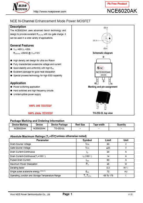
NCE N-Channel Enhancement Mode Power MOSFETDescriptionThe NCE6020AK uses advanced trench technology and design to provide excellent R DS(ON) with low gate charge. It can be used in a wide variety of applications.General Features● V DS =60V,I D =20AR DS(ON) <35m Ω @ V GS =10V● High density cell design for ultra low Rdson ● Fully characterized avalanche voltage and current ● Good stability and uniformity with high E AS ● Excellent package for good heat dissipation ● Special process technology for high ESD capabilityApplication● Power switching application● Hard switched and high frequency circuits ● Uninterruptible power supply100% UIS TESTED!100% ∆Vds TESTED!Schematic diagramMarking and pin assignmentTO-252-2L top viewPackage Marking and Ordering InformationDevice MarkingDeviceDevice PackageReel SizeTape widthQuantityNCE6020AK NCE6020AK TO-252-2L---Absolute Maximum Ratings (T C =25℃unless otherwise noted)Parameter Symbol Limit UnitDrain-Source Voltage V DS 60 V Gate-Source Voltage V GS±20 V Drain Current-ContinuousI D 20 ADrain Current-Continuous(T C =100℃) I D (100℃) 14 A Pulsed Drain Current I DM 60 A Maximum Power Dissipation P D45 W Derating factor0.3 W/℃Single pulse avalanche energy (Note 5)E AS 72 mJOperating Junction and Storage Temperature RangeT J ,T STG-55 To 175℃Thermal CharacteristicThermal Resistance,Junction-to-Case (Note 2)R θJC3.3/W ℃Electrical Characteristics (T C =25℃unless otherwise noted)Parameter Symbol ConditionMin Typ Max UnitOff CharacteristicsDrain-Source Breakdown Voltage BV DSS V GS =0V I D =250μA 60 - - V Zero Gate Voltage Drain Current I DSS V DS =60V,V GS =0V -- 1 μA Gate-Body Leakage Current I GSS V GS =±20V,V DS =0V - - ±100 nA On Characteristics (Note 3) Gate Threshold VoltageV GS(th) V DS =V GS ,I D =250μA 1.2 1.6 2.5 V Drain-Source On-State Resistance R DS(ON) V GS =10V, I D =20A - 27 35 m ΩForward Transconductance g FSV DS =5V,I D =5A 11- - S Dynamic Characteristics (Note4) Input Capacitance C lss - 500 - PFOutput CapacitanceC oss - 60 - PFReverse Transfer Capacitance C rssV DS =30V,V GS =0V,F=1.0MHz- 25 - PF Switching Characteristics (Note 4) Turn-on Delay Time t d(on) - 5 - nSTurn-on Rise Time t r - 2.6 - nS Turn-Off Delay Time t d(off) - 16.1 - nSTurn-Off Fall Time t fV DD =30V,I D =2A,R L =6.7Ω V GS =10V,R G =3Ω - 2.3 -nSTotal Gate Charge Q g - 47 nCGate-Source Charge Q gs - 6 nCGate-Drain ChargeQ gd V DS =30V,I D =4.5A,V GS =10V- 14 nC Drain-Source Diode Characteristics Diode Forward Voltage (Note 3) V SDV GS =0V,I S =20A -1.2 V Diode Forward Current (Note 2)I S - - 20 A Reverse Recovery Time t rr - 35 - nS Reverse Recovery Charge Qrr TJ = 25°C, IF =20Adi/dt = 100A/μs (Note3)- 53 - nCForward Turn-On Timet onIntrinsic turn-on time is negligible (turn-on is dominated by LS+LD)Notes:1. Repetitive Rating: Pulse width limited by maximum junction temperature.2. Surface Mounted on FR4 Board, t ≤ 10 sec .3. Pulse Test: Pulse Width ≤ 300μs, Duty Cycle ≤ 2%.4. Guaranteed by design, not subject to production5. EAS condition:Tj=25,VDD=℃30V,VG=10V,L=0.5mH,Rg=25ΩTest Circuit1) E AS test Circuit2) Gate charge test Circuit3) Switch Time Test CircuitTypical Electrical and Thermal Characteristics (Curves)Vds Drain-Source Voltage (V)Figure 1 Output CharacteristicsVgs Gate-Source Voltage (V)Figure 2 Transfer CharacteristicsI D - Drain Current (A)Figure 3 Rdson- Drain CurrentT J -Junction Temperature(℃)Figure 4 Rdson-Junction TemperatureQg Gate Charge (nC)Figure 5 Gate ChargeVsd Source-Drain Voltage (V)Figure 6 Source- Drain Diode ForwardR d s o n O n -R e s i s t a n c e (m Ω)I D - D r a i n C u r r e n t (A )I D - D r a i n C u r r e n t (A )N o r m a l i z e d O n -R e s i s t a n c eV g s G a t e -S o u r c e V o l t a g e (V )I s - R e v e r s e D r a i n C u r r e n t (A )Vds Drain-Source Voltage (V)Figure 7 Capacitance vs VdsVds Drain-Source Voltage (V)Figure 8 Safe Operation AreaT J -Junction Temperature(℃)Figure 9 BV DSS vs Junction TemperatureT J -Junction Temperature(℃)Figure 10 V GS(th) vs Junction TemperatureI D - D r a i n C u r r e n t (A )C C a p a c i t a n c e (p F )Square Wave Pluse Duration (sec)Figure 11 Normalized Maximum Transient Thermal Impedancer (t ),N o r m a l i z e d E f f e c t i v e T r a n s i e n t T h e r m a l I m p e d a n c eTO-252 Package InformationDimensions In Millimeters Dimensions In Inches SymbolMin.Max.Min.Max.A 2.200 2.400 0.087 0.094A1 0.000 0.127 0.000 0.005b 0.660 0.860 0.026 0.034c 0.460 0.580 0.018 0.023D 6.500 6.700 0.256 0.264D1 5.100 5.460 0.201 0.215 D2 0.483 TYP. 0.190 TYP.E 6.000 6.200 0.236 0.244e 2.186 2.386 0.086 0.0940.386 0.409L 9.80010.400L1 2.900 TYP. 0.114 TYP.L2 1.400 1.700 0.055 0.067 L3 1.600 TYP. 0.063 TYP.L4 0.600 1.000 0.024 0.039 Φ 1.100 1.300 0.043 0.051 θ0°8°0°8°h 0.000 0.300 0.000 0.012V 5.350 TYP. 0.211 TYP.Attention:■Any and all NCE power products described or contained herein do not have specifications that can handle applications that require extremely high levels of reliability, such as life-support systems, aircraft's control systems, or other applications whose failure can be reasonably expected to result in serious physical and/or material damage. Consult with your NCE power representative nearest you before using any NCE power products described or contained herein in such applications.■ NCE power assumes no responsibility for equipment failures that result from using products at values that exceed, even momentarily, rated values (such as maximum ratings, operating condition ranges, or other parameters) listed in products specifications of any and all NCE power products described or contained herein.■Specifications of any and all NCE power products described or contained herein stipulate the performance, characteristics, and functions of the described products in the independent state, and are not guarantees of the performance, characteristics, and functions of the described products as mounted in the customer’s products or equipment. To verify symptoms and states that cannot be evaluated in an independent device, the customer should always evaluate and test devices mounted in the customer’s products or equipment.■ NCE power Semiconductor CO.,LTD. strives to supply high-quality high-reliability products. However, any and all semiconductor products fail with some probability. It is possible that these probabilistic failures could give rise to accidents or events that could endanger human lives, that could give rise to smoke or fire, or that could cause damage to other property. When designing equipment, adopt safety measures so that these kinds of accidents or events cannot occur. Such measures include but are not limited to protective circuits and error prevention circuits for safe design, redundant design, and structural design.■ In the event that any or all NCE power products(including technical data, services) described or contained herein are controlled under any of applicable local export control laws and regulations, such products must not be exported without obtaining the export license from the authorities concerned in accordance with the above law.■No part of this publication may be reproduced or transmitted in any form or by any means, electronic or mechanical, including photocopying and recording, or any information storage or retrieval system, or otherwise, without the prior written permission of NCE power Semiconductor CO.,LTD.■Information (including circuit diagrams and circuit parameters) herein is for example only ; it is not guaranteed for volume production. NCE power believes information herein is accurate and reliable, but no guarantees are made or implied regarding its use or any infringements of intellectual property rights or other rights of third parties.■ Any and all information described or contained herein are subject to change without notice due to product/technology improvement, etc. When designing equipment, refer to the "Delivery Specification" for the NCE power product that you intend to use.■This catalog provides information as of Sep.2010. Specifications and information herein are subject to change without notice.。
Samsung 6000 6020 Series Laundry Product Guide
Product Guide6000/6020 Series LaundryWF45T6000AW – WasherDVE45T6020W – Electric Long Vent DryerDVG45T6020W – Gas Long Vent DryerTable of ContentsProduct Overview Product Overview 4Carousel Image Order 5Product Messaging Features and Benefits 7Product Specs Related Products 13Spec Sheet14Energy Guide and User Manual 15Feature Icons17WF45T6000AW – Front Load WasherProduct OverviewProduct Overview 19Carousel Image Order 20Product MessagingFeatures and Benefits 22Product SpecsRelated Products 27Spec Sheet 28User Manual 29Feature Icons31DVE45T6020W - Front Load Electric Long Vent Dryer DVG45T6020W - Front Load Gas Long Vent DryerProduct OverviewWF45T6000AW – 4.5 cu. ft. Front Load Washerwith Vibration Reduction Technology+Product OverviewProduct Long Description (299 Characters)Samsung’s ENERGY STAR ® Certified Front Load washer has 4.5 cu. ft. capacity to fit more in every load and cut down on laundry time. It is equipped with Vibration Reduction Technology+ to reduce noise for quiet washing and features Self Clean+ to eliminate 99% of bacteria that can form in the drum.11Based on testing by Intertek of the Self Clean+ cycle on the WF6000R.Product Short Description (127 Characters)Samsung’s Front Load washer offers Vibration Reduction Technology+ and Self Clean+ to eliminate 99% of bacteria from the drum.1Product Title4.5 cu. ft. Front Load Washer with Vibration Reduction Technology+Available ColorWhiteModel Number: WF45T6000AW UPC: 887276394794123461112891075: /mm/nicePath/easyads?nav=pr658559408 : /mm/nicePath/easyads?nav=pr658559385Product MessagingWF45T6000AW – 4.5 cu. ft. Front Load Washerwith Vibration Reduction Technology+N/AEasy Ads links: /mm/nicePath/easyads?nav=pr658559409 /mm/nicePath/easyads?nav=pr658559386Product SpecsWF45T6000AW – 4.5 cu. ft. Front Load Washer with Vibration Reduction Technology+Related ProductsSpec SheetEasy Ads link /mm/nicePath/easyads?nav=pr658559288Vibration Reduction Technology+Rating ENERGY STAR ®-rated CEE Tier 2IMEF = 2.95Features• 4.5 cu. ft. Capacity • V ibration Reduction Technology+• Self Clean+1• S mart Care • 10 Preset Washing Cycles • 6 Additional Washing Options • 5 Temperature Levels • L ED Display: Ice Blue Available Color White Self Clean+Washer Spec Sheet - front Washer Spec Sheet - backEnergy Guide and User ManualEasy Ads link/mm/nicePath/easyads?nav=pr658559288WasherU ser manualW F45T6000A*Energy Guide User ManualUntitled-7 14/2/2020 2:56:32 PMFeature IconsWF45T6000AW – 4.5 cu. ft. Front Load Washer with Vibration Reduction Technology+Feature IconsSmart Care Large 4.5 cu. ft.CapacityVibration ReductionTechnology+ENERGY STAR®CertifiedSelf Clean+Product OverviewDVE45T6020W & DVG45T6020W - 7.5 cu. ft. Front Load Long Vent Dryer with Sensor DryProduct OverviewProduct Long Description (278 Characters)Samsung’s newest long vent dryer, with up to 120-foot venting ability, features Sensor Dry, which optimizes cycle time and temperature to thoroughly and safely dry your clothes. And, with its 7.5 cu. ft. capacity and 10 preset drying cycles, you can do fewer loads in less time.Product Short Description (103 Characters)Samsung’s 7.5 cu. ft. capacity dryer’s long hose vents up to 120 feet, for more flexible installation.Product Title7.5 cu. ft. Electric (Gas) Long Vent Dryer with Sensor DryAvailable ColorWhite Model Number: DVE45T6020W UPC: 887276438153Model Number: DVG45T6020W UPC: 8872764381601234789101112: /mm/nicePath/easyads?nav=pr658559838 : /mm/nicePath/easyads?nav=pr658559804Product MessagingDVE45T6020W & DVG45T6020W - 7.5 cu. ft. Front LoadLong Vent Dryer with Sensor DryProduct SpecsDVE45T6020W & DVG45T6020W - 7.5 cu. ft. Front Load Long Vent Dryer with Sensor DryRelated ProductsSpec SheetsFeatures• Sensor Dry• 7.5 cu. ft. Large Capacity 7.5 cu. ft. Large CapacitySensor DryAvailable ColorWhiteElectrical Requirements:- 120V / 60Hz - 15 AmpsEasy Ads link/mm/nicePath/easyads?nav=pr658844097Gas Dryer Spec Sheet - front Gas Dryer Spec Sheet - backElectric Dryer Spec Sheet - front Electric Dryer Spec Sheet - back Features• Sensor Dry• 7.5 cu. ft. Large Capacity Rating:644 kWh/yr7.5 cu. ft. Large CapacitySensor DryAvailable ColorWhiteElectrical Requirements:Easy Ads link/mm/nicePath/easyads?nav=pr658844097User Manual Easy Ads linkDryerUser manualDVE(G)45T6005*/DVE(G)45T6000*Feature IconsDVE45T6020W & DVG45T6020W - 7.5 cu. ft. Front Load Long Vent Dryer with Sensor DryFeature IconsDryer:Icons Smart Care Sensor Dry Large 7.5 cu. ft. Capacity Lint Filter Indicator10 Preset Drying Cycles Interior Drum Light Long Vent Drying。
DVT6020EU快速安装指南(新)

PAGE 8
视频点播设置
点播服务器
普通用户 特殊用户 安装调试人员 视频点播服务器: 10.27.65.25 党建平台服务器: 10.27.65.160 测试服务器: 10.27.65.18
设置方法: 系统菜单->系统选项->服务器设置
PAGE 9
安装指南
机顶盒出厂默认输出视频格式为576i-50Hz
576i/576的节目源宽高比16:9 标清频道的节目源宽高比4:3
PAGE 4
视频介绍2
如何才能体验真正的高清电视?
高清节目源+高清机顶盒+高清显示设备
PAGE 5
视频介绍3
问题1: 问题 :
标清频道节目在机顶盒高清输出 高清输出时是不是高清效果? 高清输出 答案: 答案:是 标清片源被机顶盒转换为高清信号输出,一定程度上提 升了输出图像质量。
设置方式:按遥控器 “音效”键 -- 音效选择
PAGE 7
用户设置/系统设置
用户设置(普通家庭用户)
默认密码1234,搜索网络参数不可修改。 可设置不同视频格式(576i/576P/720P/1080i) 执行“恢复出厂”时只恢复用户设置参数,不恢复系统设置参数。
系统设置(安装调试人员)
默认密码4321。 可设置不同机顶盒工作模式。 可设置不同遥控器协议类型, 建议设置为“所有”。 可设置点播服务器IP地址。 可修改搜索网络参数。 执行“恢复出厂”时恢复全部机顶盒设置参数。
高清电视看到的就是高清效果。
高清电视也向下兼容标清信号。
PAGE 17
上海高清机顶盒功能对比
DVT-6020EU DVT-6020 Cisco8488 TZ-SCH1001 DVT-5610 DVT-5600
2011年深圳飞毛腿电池通用型号

序号品牌型号原装型号艾罗威容量原装电容量1诺基亚2600c BL-5BT 9008702诺基亚2680BL-4S8608603诺基亚3100BL-5C 11509704诺基亚N72BL-5C 11009705诺基亚3220BL-5B 9508206诺基亚N83BL-5B 9008207诺基亚5220BL-5CT 11508608诺基亚5310BL-4CT 9508609诺基亚5800BL-5J 1420132010诺基亚6100BL-4C 102090011诺基亚6131BL-4C 95090012诺基亚6111BL-4B 83070013诺基亚7390BP-5M 100090014诺基亚5700BP-5M 90090015诺基亚7710BP-5L 1700150016诺基亚7900BL-6P 89083017诺基亚6500c BL-6P 70083018诺基亚8800BL-5X/6X 70060019诺基亚8900BL-4U11201000诺基亚 N O K I A飞毛腿电子(深圳)有艾罗威型号表SCUD Electronic (Shenzhen) Co., Ltd飞毛腿电池型号表-2010.11 SCUD Battery3.Welcome to propose new products' demand or pro2、以上数据仅供参考,因设计改进或电芯品质提升,容量会有所调整,最终容量请以实物铭牌标称为准!3、欢迎提出新品需求或提供电池通用信息!Annotation:1. “★” stands for those new products that will soon come into market.2. Above data is only for your reference. Due to desig accordingly.The exact capacity is signed on the mark on the products.o n圳)有限公司型号表d FAX:0755-********/33810161 tery model form-September 2010终容量请以实物铭牌标称为准!s that will soon come into market.design or core improving, the battery capacity might be adjusted mark on the products.r provide universal battery information.。
常用纽扣电池型号对照表

常用纽扣电池型号对照表常用纽扣电池型号对照表CR纽扣电池,CR表示锂-二氧化锰,CR后面的4位数字,前两位是直径,后两位是高,例如:CR2032是指一种20mm直径,3.2mm 高。
附:锌锰电池型号命名与标识说明:IEC标准中,R代表圆柱形,L代表碱性,数字代表电池的大小,数字后面的P代表高功率,这里有一个特殊规定,在表示五号普通锌锰电池时,要标识为R6P,而不是R06或者R6。
CR系列也是一种典型的干电池型号,常见的有CR2025、CR2032等。
其中C是以锂金属为负极,以二氧化锰为正极的化学电池体系,R表示电池的形状为圆柱形,如果是方形则F替代;20表示电池的直径是20mm,32代表电池的高度为3.2mm。
除了单支干电池型号命名外,还有一些组合干电池型号的标识表示如下:1、9V电池:6F22是由6个扁平形电池叠层的碳性电池;6LR61则是由6个扁平形电池叠层的碱性电池;2、AG系列:是直径很小的CR电池,分为AG1到AG13计13种,属于碱性电池;3、23A和27A:是由八个同一规格的AG电池叠层的,也称12V 扣式电池,27A大于23A。
这些组合的干电池型号往往是基于特殊电压或者容量的考虑,也只适用于一些特定领域。
由于这些干电池型号有一定的市场容量,知道它们属于干电池序列这一点,就便于把握其价格与特性。
另外还有非锌锰和锂锰系的干电池,如镁锰电池等,因为比较少见,所以对这种干电池及干电池型号介绍不多。
普通充电电池充电时间计算一、充电常识在这里,首先要说明的是,充电是使用充电电池的重要步骤。
适当合理的充电对延长电池寿命很有好处,而野蛮胡乱充电将会对电池寿命有很大影响。
上一篇曾说过,目前的锂电池基本都是根据各个产品单独封装,互不通用的,因此各个产品也提供各自的充电设备,互不通用,在使用时只要遵循各自的说明书使用即可。
所以本篇对电池充电的介绍主要是指镍镉电池和镍氢电池。
对镍隔电池和镍氢电池充电有两种方式,就是我们大家所熟知的“快充”和“慢充”。
PMEG6020ER,115;中文规格书,Datasheet资料
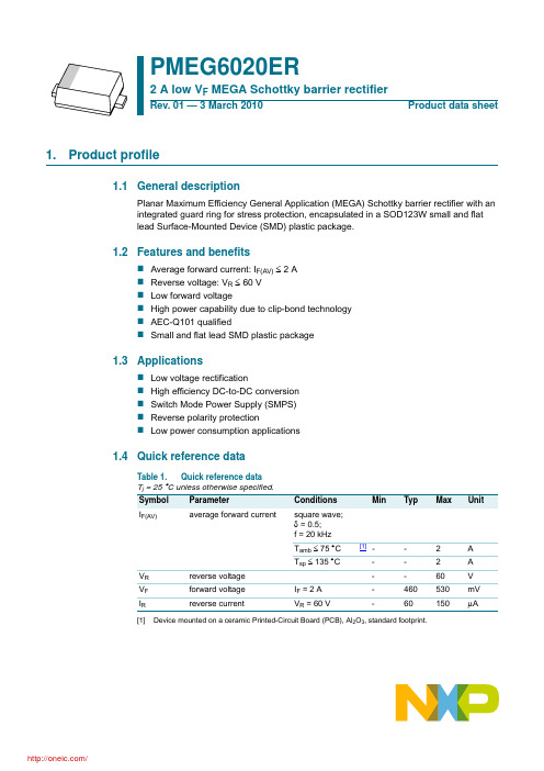
Symbol
Parameter
Conditions
Min
Tj
junction temperature
-
Tamb
ambient temperature
−55
Tstg
storage temperature
−65
Max Unit
150
°C
+150 °C
+150 °C
[1] Device mounted on a ceramic PCB, Al2O3, standard footprint. [2] Tj = 25 °C prior to surge. [3] Reflow soldering is the only recommended soldering method. [4] Device mounted on an FR4 PCB, single-sided copper, tin-plated and standard footprint. [5] Device mounted on an FR4 PCB, single-sided copper, tin-plated, mounting pad for cathode 1 cm2.
PMEG6020ER
2 A low VF MEGA Schottky barrier rectifier
102
Zth(j-a) (K/W)
10
duty cycle =
1 0.75 0.5
0.33 0.25
0.2
0.1 0.05
0.02 0.01 1
0
006aab651
10−1
10−3
10−2
10−1
[1]
真空干燥箱(DZF-6020)使用说明
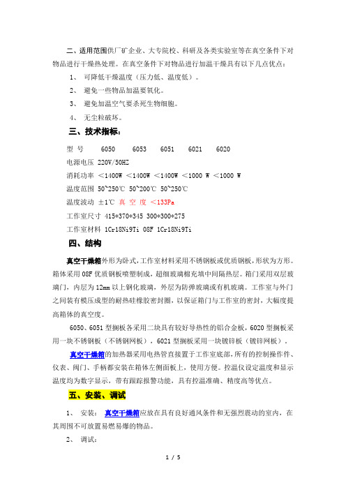
二、适用范围供厂矿企业、大专院校、科研及各类实验室等在真空条件下对物品进行干燥热处理。
在真空条件下对物品进行加温干燥具有以下几点优点:1、可降低干燥温度(压力低、温度低)。
2、避免一些物品加温要氧化。
3、避免加温空气要杀死生物细胞。
4、无尘粒破坏。
三、技术指标:型号 6050 6053 6051 6021 6020电源电压 220V/50HZ消耗功率<1400W <1400W <1400W <1000 W <1000 W温度范围50~250℃ 50~200℃ 50~250℃温度波动±1℃真空度<133Pa工作室尺寸 415*370*345 300*300*275工作室材料 1Cr18Ni9Ti 08F 1Cr18Ni9Ti四、结构真空干燥箱外形为卧式,工作室材料采用不锈钢板或优质钢板,形状为方形。
箱体采用08F优质钢板喷塑制成,超细玻璃棉充填中间隔热层。
箱门采用双层玻璃门,内层为12mm以上钢化玻璃,外层为防弹玻璃或有机玻璃。
工作室与外门之间装有模压成型的耐热硅橡胶密封圈,以保证箱门与工作室的密封,大幅度提高箱体的真空度。
6050、6051型搁板各采用二块具有较好导热性的铝合金板,6020型搁板采用一块不锈钢板(不锈钢网板),6021型搁板采用一块镀锌板(镀锌网板)。
真空干燥箱的加热器采用电热管直接置于工作室底部,所有的控制操作件、仪表、阀门、手柄都安装在箱体左侧面板上,使用方便。
控温仪设定温度和显示温度均为数字显示,带有跟踪报警功能,具有控温准确、精度高等优点。
五、安装、调试1、安装:真空干燥箱应放在具有良好通风条件和无强烈震动的室内,在其周围不可放置易燃易爆的物品。
2、调试:(1)将箱门关上并将拉手旋紧,关闭放气阀,开启真空阀。
(2)将真空干燥箱侧面的导气管用真空橡胶管与真空泵连接,接通真空泵电源,开始抽气,当真空表指示值达到-0.1M Pa时,关闭真空泵和真空泵电源,此时箱内处于真空状态,如无加热要求,真空干燥箱调试结束。
6020轴承标准尺寸
6020轴承标准尺寸6020轴承是一种常见的滚动轴承,其标准尺寸对于机械设备的设计和制造具有重要意义。
了解6020轴承的标准尺寸,对于工程师和设计师来说至关重要。
本文将介绍6020轴承的标准尺寸及其相关知识,希望能为相关领域的专业人士提供一些参考价值。
首先,我们来看6020轴承的外形尺寸。
6020轴承的外径为150mm,内径为100mm,厚度为24mm。
这是其最基本的外形尺寸,也是设计和安装时需要首先考虑的参数。
外形尺寸的准确度对于轴承的性能和使用寿命有着直接的影响,因此在制造和安装过程中需要严格控制。
其次,我们需要了解6020轴承的额定负荷和额定速度。
6020轴承的额定动载荷为54kN,额定静载荷为36kN。
这些参数是在标准测试条件下得出的,可以作为设计时的参考数值。
同时,6020轴承的额定速度为4500转/分钟,这也是在标准条件下的数值。
在实际应用中,需要根据具体的工况条件对这些参数进行修正和调整。
除此之外,6020轴承的安装尺寸也是非常重要的。
安装尺寸包括安装孔尺寸、轴肩直径和轴肩高度等参数。
这些尺寸的准确度直接影响着轴承的安装质量和性能。
因此,在设计和制造过程中,需要严格按照相关标准对这些尺寸进行控制和检测。
另外,6020轴承的密封和润滑也是需要考虑的重要因素。
密封结构和润滑方式直接影响着轴承的使用寿命和性能表现。
在选择和设计密封结构和润滑方式时,需要综合考虑轴承的工作环境、转速、负荷等因素,以确保轴承能够在各种工况下都能够正常工作。
最后,我们需要注意6020轴承的相关配件尺寸。
如轴承座的尺寸、轴承套圈的尺寸等。
这些配件的尺寸和几何形状对于轴承的安装和工作都有着重要的影响,因此在设计和选择时需要特别注意。
总之,6020轴承的标准尺寸对于相关领域的专业人士来说是非常重要的。
了解和掌握6020轴承的标准尺寸,可以帮助工程师和设计师在设计和制造过程中更加准确地选择和使用轴承,从而提高机械设备的性能和可靠性。
ADG602BRMZ中文资料

2 Ω, CMOS, ±5 V/+5 VSPST SwitchesADG601/ADG602 Rev. CInformation furnished by Analog Devices is believed to be accurate and reliable. However, noresponsibility is assumed by Analog Devices for its use, nor for any infringements of patents or other rights of third parties that may result from its use. Specifications subject to change without notice. No license is granted by implication or otherwise under any patent or patent rights of Analog Devices. T rademarks and registered trademarks are the property of their respective owners. One Technology Way, P.O. Box 9106, Norwood, MA 02062-9106, U.S.A. Tel: 781.329.4700 Fax: 781.461.3113 ©2001–2007 Analog Devices, Inc. All rights reserved.FEATURESLow on resistance, 2.5 Ω maximum<0.65 Ω on-resistance flatnessDual ±2.7 V to ±5.5 V or single +2.7 V to +5.5 V suppliesRail-to-rail input signal rangeTiny, 6-lead SOT-23; 8-lead MSOP; and 820 μm × 2255 μm die Low power consumptionTTL-/CMOS-compatible inputsAPPLICATIONSAutomatic test equipmentPower routingCommunication systemsData acquisition systemsSample-and-hold systemsAvionicsRelay replacementBattery-powered systemsFUNCTIONAL BLOCK DIAGRAMSNOTES1. SWITCHES SHOWN FOR A LOGIC 0 INPUT.02619-1Figure 1.Table 1. Truth TableADG601 IN ADG602 IN Switch Condition0 1 Off1 0 OnGENERAL DESCRIPTIONThe ADG601/ADG602 are monolithic, CMOS single-pole single-throw (SPST) switches with on resistance typically less than 2.5 Ω. The low on-resistance flatness makes theADG601/ADG602 ideally suited to many applications, particularly those requiring low distortion. These switches are ideal replacements for mechanical relays because they are more reliable, have lower power requirements, and are available in much smaller package sizes.The ADG601 is a normally open (NO) switch, and the ADG602 is a normally closed (NC) switch. Each switch conducts equally well in both directions when the device is on, with the input signal range extending to the supply rails.The switches are available in tiny, 6-lead SOT-23; 8-lead MSOP; and 820 μm × 2255 μm die.PRODUCT HIGHLIGHTS1.Low on resistance (2 Ω typical)2.Dual ±2.7 V to ±5.5 V or single +2.7 V to +5.5 V supplies3.Tiny, 6-lead SOT-23; 8-lead MSOP; and 820 μm × 2255 μm die4.Rail-to-rail input signal rangeADG601/ADG602Rev. C | Page 2 of 12TABLE OF CONTENTSFeatures..............................................................................................1 Applications.......................................................................................1 Functional Block Diagrams.............................................................1 General Description.........................................................................1 Product Highlights...........................................................................1 Revision History...............................................................................2 Specifications.....................................................................................3 Dual Supply...................................................................................3 Single Supply.................................................................................4 Absolute Maximum Ratings............................................................5 ESD Caution...................................................................................5 Pin Configurations and Function Descriptions............................6 Typical Performance Characteristics..............................................7 Terminology.......................................................................................9 Test Circuits.....................................................................................10 Outline Dimensions.......................................................................11 Ordering Guide.. (11)REVISION HISTORY3/07—Rev. B to Rev. CAdded Die Package.............................................................Universal Changes to Specifications.................................................................3 Added Figure 4 and Table 6..............................................................6 Changes to Ordering Guide..........................................................11 3/06—Rev. A to Rev. BUpdated Format..................................................................Universal Changes to 6-Lead SOT-23 (RJ-6) Pin Configuration.................6 Added Pin Function Descriptions Table........................................6 Changes to Figure 19.........................................................................9 Updated Outline Dimensions........................................................11 Changes to Ordering Guide...........................................................11 6/03—Rev. 0 to Rev. AChanges to Specifications.................................................................2 Changes to Ordering Guide.............................................................4 Updated Outline Dimensions. (8)ADG601/ADG602Rev. C | Page 3 of 12SPECIFICATIONSDUAL SUPPLYV DD = 5 V ± 10%, V SS = –5 V ± 10%, GND = 0 V , unless otherwise noted. Table 2.B Version 1 Parameter +25°C −40°C to +85°C Unit Test Conditions/Comments ANALOG SWITCH Analog Signal Range V SS to V DD V V DD = +4.5 V, V SS = –4.5 V On Resistance (R ON ) 2 Ω typ V S = ±4.5 V, I DS = −10 mA; see Figure 15 2.5 5.5 Ω max On-Resistance Flatness (R FLAT (ON)) 0.35 0.4 Ω typ V S = ±3.3 V, I DS = −10 mA 0.6 0.65 Ω max LEAKAGE CURRENTS V DD = +5.5 V, V SS = −5.5 V Source Off Leakage, I S (Off) ±0.01 nA typ V S = +4.5 V/−4.5 V, V D = −4.5 V/+4.5 V; see Figure 16 ±0.25 ±1 nA max Drain Off Leakage, I D (Off) ±0.01 nA typ V S = +4.5 V/−4.5 V, V D = −4.5 V/+4.5 V; see Figure 16 ±0.25 ±1 nA max Channel On Leakage, I D , I S (On) ±0.01 nA typ V S = V D = +4.5 V or −4.5 V; see Figure 17 ±0.25 ±1 nA max DIGITAL INPUTS Input High Voltage, V INH 2.4 V min Input Low Voltage, V INL 0.8 V max Input Current, I INL or I INH 0.005 μA typ V IN = V INL or V INH ±0.1 μA max Digital Input Capacitance, C IN 2 pF typ DYNAMIC CHARACTERISTICS 2 t ON 80 ns typ R L = 300 Ω, C L = 35 pF 120 155 ns max V S = 3.3 V; see Figure 18t OFF 45 ns typ R L = 300 Ω, C L = 35 pF 75 90 ns max V S = 3.3 V; see Figure 18Charge Injection 250 pC typ V S = 0 V, R S = 0 Ω, C L = 1 nF; see Figure 19Off Isolation −60 dB typ R L = 50 Ω, C L = 5 pF, f = 1 MHz; see Figure 20Bandwidth −3 dB 180 MHz typ R L = 50 Ω, C L = 5 pF; see Figure 21C S (Off) 50 pF typ f = 1 MHz C D (Off) 50 pF typ f = 1 MHz C D , C S (On) 145 pF typ f = 1 MHz POWER REQUIREMENTS V DD = +5.5 V, V SS = −5.5 V I DD 0.001 μA typ Digital inputs = 0 V or 5.5 V 1.0 μA max I SS 0.001 μA typ Digital inputs = 0 V or 5.5 V 1.0 μA max1 Temperature range for B version is −40°C to +85°C. 2Guaranteed by design, not subject to production test.ADG601/ADG602Rev. C | Page 4 of 12SINGLE SUPPLYV DD = 5 V ± 10%, V SS = 0 V , GND = 0 V , unless otherwise noted. Table 3.B Version 1 Parameter +25°C −40°C to +85°C Unit Test Conditions/Comments ANALOG SWITCH Analog Signal Range 0 V to V DD V V DD = 4.5 V On Resistance (R ON ) 3.5 Ω typ V S = 0 V to 4.5 V, I DS = −10 mA; see Figure 15 5 8 Ω max On-Resistance Flatness (R FLAT (ON)) 0.2 0.2 Ω typ V S = 1.5 V to 3.3 V, I DS = –10 mA 0.6 Ω max LEAKAGE CURRENTS V DD = 5.5 V Source Off Leakage, I S (Off) ±0.01 nA typ V S = 4.5 V/1 V, V D = 1 V/4.5 V; see Figure 16 ±0.25 ±1 nA max Drain Off Leakage, I D (Off) ±0.01 nA typ V S = 4.5 V/1 V, V D = 1 V/4.5 V; see Figure 16 ±0.25 ±1 nA max Channel On Leakage, I D , I S (On) ±0.01 nA typ V S = V D = 4.5 V or 1 V; see Figure 17 ±0.25 ±1 nA max DIGITAL INPUTS Input High Voltage, V INH 2.4 V min Input Low Voltage, V INL 0.8 V max Input Current, I INL or I INH 0.005 μA typ V IN = V INL or V INH ±0.1 μA max Digital Input Capacitance, C IN 2 pF typDYNAMIC CHARACTERISTICS 2t ON 110 ns typ R L = 300 Ω, C L = 35 pF 220 280 ns max V S = 3.3 V; see Figure 18t OFF 50 ns typ R L = 300 Ω, C L = 35 pF 80 110 ns max V S = 3.3 V; see Figure 18Charge Injection 20 pC typ V S = 0 V, R S = 0 Ω, C L = 1 nF; see Figure 19Off Isolation −60 dB typ R L = 50 Ω, C L = 5 pF, f = 1 MHz; see Figure 20Bandwidth –3 dB 180 MHz typ R L = 50 Ω, C L = 5 pF; see Figure 21C S (Off) 50 pF typ f = 1 MHz C D (Off) 50 pF typ f = 1 MHz C D , C S (On) 145 pF typ f = 1 MHz POWER REQUIREMENTS V DD = 5.5 V I DD 0.001 μA typ Digital inputs = 0 V or 5.5 V 1.0 μA max1 Temperature range for B version is −40°C to +85°C. 2Guaranteed by design, not subject to production test.ADG601/ADG602Rev. C | Page 5 of 12ABSOLUTE MAXIMUM RATINGST A = 25°C, unless otherwise noted. Table 4.Parameter RatingV DD to V SS 13 VV DD to GND −0.3 V to +6.5 VV SS to GND +0.3 V to –6.5 VAnalog Inputs 1V SS − 0.3 V to V DD + 0.3 VDigital Inputs 1−0.3 V to V DD + 0.3 V or30 mA (whicheveroccurs first)Continuous Current, S or D 100 mAPeak Current, S or D (Pulsed at 1 ms, 10% Duty Cycle Max) 200 mA Operating Temperature Range Industrial (B Version) −40°C to +85°C Storage Temperature Range −65°C to +150°C Junction Temperature 150°C Thermal ResistanceMSOP θJA 206°C/W θJC 44°C/W SOT-23θJA 229.6°C/W θJC 91.99°C/W Lead Temperature, Soldering (10 sec) 300°C IR Reflow, Peak Temperature 220°C1Overvoltages at IN, S, or D are clamped by internal diodes. Current should be limited to the maximum ratings given.Stresses above those listed under Absolute Maximum Ratings may cause permanent damage to the device. This is a stress rating only; functional operation of the device at these or any other conditions above those indicated in the operational section of this specification is not implied. Exposure to absolute maximum rating conditions for extended periods may affect device reliability. Only one absolute maximum rating may be applied at a time. ESD CAUTIONADG601/ADG602Rev. C | Page 6 of 12PIN CONFIGURATIONS AND FUNCTION DESCRIPTIONSV DDS V SS 02619-002DNC NC V DD SSNC =NO CONNECT02619-003Figure 2. 6-Lead SOT-23 (RJ-6) Figure 3. 8-Lead MSOP (RM-8) Figure 4. Die (820 μm × 2255 μm)Table 5. Pin Function DescriptionsPin No.6-Lead SOT-23 8-Lead MSOP Mnemonic Description1 4 V DD Most Positive Power Supply Potential.2 8 S Source Terminal. Can be an input or output.3 5 V SS Most Negative Power Supply Potential.4 7 GND Ground (0 V) Reference.5 1 D Drain Terminal. Can be an input or output.6 6 IN Logic Control Input. N/A 2, 3 NC No Connect.Table 6. Die Pad Coordinates 1Die Pad CoordinatesDie Pad No. X (μm) Y (μm) Mnemonic Description 1 −265 +754 NC No Connect. 2 −265 +525 D Drain Terminal. Can be an input or output.2 3 −265 +241 D Drain Terminal. Can be an input or output.2 4 −265 +141 D Drain Terminal. Can be an input or output.2 5 −265 −191 NC No Connect. 6 −265 −409 NC No Connect. 7 −265 −549 NC No Connect. 8 −265 −787 V DD Most Positive Power Supply Potential. 9 +265 −767 V SS Most Negative Power Supply Potential. 10 +265 −429 IN Logic Control Input. 11 +265 −289 GND Ground (0 V) Reference. 12 +265 +189 S Source Terminal. Can be an input or output.313 +265 +521 S Source Terminal. Can be an input or output.314 +265 +661 NC Source Terminal. Can be an input or output.1 Measured from the center of the die.2Bond the D pads together to a single point to preserve the on resistance and current handling capability. The common point acts as the drain pin of the switch. 3Bond the S pads together to a single point to preserve the on resistance and current handling capability. The common point acts as the source pin of the switch.ADG601/ADG602Rev. C | Page 7 of 12TYPICAL PERFORMANCE CHARACTERISTICS540321V D ,V S (V)O N R E S I S T A N C E (Ω)–5–4–3–2–101234502619-004Figure 5. On Resistance vs. V D , V S (Dual Supply)108064239157V D ,V S (V)0.51.01.52.02.53.0 3.54.04.55.0O N R E S I S T A N C E (Ω)02619-005Figure 6. On Resistance vs. V D , V S (Single Supply) 540321V D ,V S (V)–5–4–3–2–1012345O N R E S I S T A N C E (Ω)02619-006Figure 7. On Resistance vs. V D, V S for Different Temperatures (Dual Supply)O N R E S I S T A N C E (Ω)54321V D ,V S (V)00.5 1.0 1.5 2.02.53.0 3.54.0 4.55.002619-007Figure 8. On Resistance vs. V D , V S for Different Temperatures (Single Supply)L E A K A G E C U R R E N T (n A )0.50.3–0.50.1–0.1–0.3–0.20.4–0.400.2TEMPERATURE (°C)010203040506070808502619-009Figure 9. Leakage Currents vs. Temperature (Dual Supply)L E A K A G E C U R R E N T (n A )0.50.3–0.50.10–0.1–0.3–0.20.4–0.40.2TEMPERATURE (°C)010203040506070808502619-008Figure 10. Leakage Currents vs. Temperature (Single Supply)ADG601/ADG602Rev. C | Page 8 of 12C H A R G E I N J E C T I O N (p C )50040030020010015045050250350V S (V)–5–4–3–2–101234502619-010Figure 11. Charge Injection vs. Source Voltage T I M E (n s )180160080604020140100120TEMPERATURE (°C)–40–202040608002619-011Figure 12. t ON /t OFF Times vs. Temperature FREQUENCY (MHz)0–10–80–20–30–70–40–50–60O F F I S O L A T I O N (d B )0.211010002619-012Figure 13. Off Isolation vs. FrequencyFREQUENCY (MHz)–2–12–4–6–10–8O N R E S P O N S E (d B )0.211010040002619-013Figure 14. On Response vs. FrequencyADG601/ADG602Rev. C | Page 9 of 12TERMINOLOGYV DDMost positive power supply potential. V SSMost negative power supply potential. I DDPositive supply current. I SSNegative supply current. GNDGround (0 V) reference.SSource terminal. Can be an input or an output. DDrain terminal. Can be an input or an output. INLogic control input.V D , V SAnalog voltage on Terminal D and Terminal S. R ONOhmic resistance between Terminal D and Terminal S. R FLAT (ON)Flatness is defined as the difference between the maximum and minimum values of on resistance as measured over the specified analog signal range.I S (Off)Source leakage current with the switch off. I D (Off)Drain leakage current with the switch off. I D , I S (On)Channel leakage current with the switch on. V INLMaximum input voltage for Logic 0. V INHMinimum input voltage for Logic 1. I INL (I INH )Input current of the digital input.C S (Off)Off switch source capacitance. Measured with reference to ground. C D (Off)Off switch drain capacitance. Measured with reference to ground. C D , C S (On)On switch capacitance. Measured with reference to ground. C INDigital input capacitance.t ONDelay between applying the digital control input and the output switching on.t OFFDelay between applying the digital control input and the output switching off.Charge InjectionA measure of the glitch impulse transferred from the digital input to the analog output during switching.Off IsolationA measure of unwanted signal coupling through an off switch. On ResponseFrequency response of the on switch. Insertion LossLoss due to the on resistance of the switch.ADG601/ADG602Rev. C | Page 10 of 12TEST CIRCUITSV 02619-014Figure 15. On ResistanceV 02619-015Figure 16. Off Leakage02619-016Figure 17. On LeakageV V V V V V02619-017Figure 18. Switching TimesOUTV V V IN V IN V OUT02619-018Figure 19. Charge InjectionV V OFF ISOLATION =20 logV OUT V S02619-019Figure 20. Off Isolation V V INSERTION LOSS =20 logV OUT WITH SWITCH V S WITHOUT SWITCH02619-020Figure 21. BandwidthADG601/ADG602Rev. C | Page 11 of 12OUTLINE DIMENSIONSCOMPLIANT TO JEDEC STANDARDS MO-187-AAPLANE0.10Figure 22. 8-Lead Mini Small Outline Package [MSOP](RM-8)Dimensions shown in millimetersCOMPLIANT TO JEDEC STANDARDS MO-178-ABFigure 23. 6-Lead Small Outline Transistor Package [SOT-23](RJ-6)Dimensions shown in millimetersORDERING GUIDEModelTemperature Range Package Description Package Option Branding 1ADG601BRT-REEL −40°C to +85°C 6-Lead SOT-23 RJ-6 STB ADG601BRT-REEL7 −40°C to +85°C 6-Lead SOT-23 RJ-6 STB ADG601BRTZ-REEL 2−40°C to +85°C 6-Lead SOT-23 RJ-6 STB# ADG601BRTZ-REEL72−40°C to +85°C 6-Lead SOT-23 RJ-6 STB# ADG601BRM−40°C to +85°C 8-Lead MSOP RM-8 STB ADG601BRM-REEL−40°C to +85°C8-Lead MSOP RM-8STBADG601BRM-REEL7 −40°C to +85°C 8-Lead MSOP RM-8 STB ADG601BRMZ 2−40°C to +85°C 8-Lead MSOP RM-8 S1G ADG601BRMZ-REEL 2−40°C to +85°C 8-Lead MSOP RM-8 S1G ADG601BRMZ-REEL72−40°C to +85°C 8-Lead MSOPRM-8S1GADG601CSURF Die ADG602BRT-REEL −40°C to +85°C 6-Lead SOT-23 RJ-6 SUB ADG602BRT-REEL7 −40°C to +85°C 6-Lead SOT-23 RJ-6 SUB ADG602BRTZ-REEL 2 −40°C to +85°C 6-Lead SOT-23 RJ-6 S18 ADG602BRTZ-REEL72 −40°C to +85°C 6-Lead SOT-23 RJ-6 S18 ADG602BRM −40°C to +85°C 8-Lead MSOP RM-8 SUB ADG602BRM-REEL −40°C to +85°C 8-Lead MSOP RM-8 SUB ADG602BRM-REEL7 −40°C to +85°C 8-Lead MSOP RM-8 SUB ADG602BRMZ 2−40°C to +85°C 8-Lead MSOP RM-8 S18 ADG602BRMZ-REEL72−40°C to +85°C8-Lead MSOPRM-8S181 Branding on SOT-23 and MSOP is limited to three characters due to space constraints.2Z = RoHS Compliant Part, # denotes RoHS compliant product, may be top or bottom marked.ADG601/ADG602Rev. C | Page 12 of 12NOTES©2001–2007 Analog Devices, Inc. All rights reserved. Trademarks and registered trademarks are the property of their respective owners. D02619-0-3/07(C)。
MUR6020PT中文资料
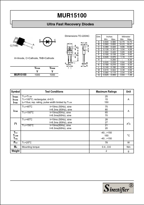
MUR15100
Ultra Fast Recovery Diodes
Fig. 1 Forward current versus voltage drop.
Fig. 2 Recovery charge versus -diF/dt.
Fig. 3 Peak reverse current versus -diF/dt.
MUR15100
Ultra Fast Recovery Diodes
Dimensions TO-220AC A C(TAB) A C C
Dim. A B C D E F G H J K L M N Q
A=Anode, C=Cathode, TAB=Cathode
MUR15100
VRSM V 1000
Fig. 4 Dynamic parameters versus junction temperature.
Fig. 5 Recovery time versus -diF/dt.
Fig. 6 Peak forward voltage versus diF/dt.
Fig. 7 Transient thermal impedance junction to case.
ADVANTAGES
* High reliability circuit operation * Low voltage peaks for reduced protection circuits * Low noise switching * Low losses * Operating at lower temperature or space saving by reduced cooling
VRRM V 1000
- 1、下载文档前请自行甄别文档内容的完整性,平台不提供额外的编辑、内容补充、找答案等附加服务。
- 2、"仅部分预览"的文档,不可在线预览部分如存在完整性等问题,可反馈申请退款(可完整预览的文档不适用该条件!)。
- 3、如文档侵犯您的权益,请联系客服反馈,我们会尽快为您处理(人工客服工作时间:9:00-18:30)。
The products listed in this document are designed to be used with ordinary electronic equipment or devices (such as audio visual equipment, office-automation equipment, communications devices, electrical appliances and electronic toys). Should you intend to use these products with equipment or devices which require an extremely high level of reliability and the malfunction of with would directly endanger human life (such as medical instruments, transportation equipment, aerospace machinery, nuclear-reactor controllers, fuel controllers and other safety devices), please be sure to consult with our sales representative in advance. About Export Control Order in Japan Products described herein are the objects of controlled goods in Annex 1 (Item 16) of Export Trade Control Order in Japan. In case of export from Japan, please confirm if it applies to "objective" criteria or an "informed" (by MITI clause) on the basis of "catch all controls for Non-Proliferation of Weapons of Mass Destruction.
Japan / (Internal Sales)
Tokyo Yokohama Nagoya Kyoto 2-1-1, Yaesu, Chuo-ku, Tokyo 104-0082 TEL : +81(3)5203-0321 FAX : +81(3)5203-0300 2-4-8, Shin Yokohama, Kohoku-ku, Yokohama, Kanagawa 222-8575 TEL : +81(45)476-2131 FAX : +81(45)476-2128 Dainagayo Building 9F 3-28-12, Meieki, Nakamura-ku, Nagoya,Aichi 450-0002 TEL : +81(52)581-8521 FAX : +81(52)561-2173 579-32 Higashi Shiokouji-cho, Karasuma Nishi-iru, Shiokoujidori, Shimogyo-ku, Kyoto 600-8216 TEL : +81(75)311-2121 FAX : +81(75)314-6559 TEL : +81(45)476-9270 FAX : +81(045)476-9271
Please contact our sales offices for details ;
U.S.A / San Diego Atlanta Dallas Germany / Dusseldorf TEL : +1(858)625-3630 TEL : +1(770)754-5972 TEL : +1(972)312-8818 TEL : +49(2154)9210 FAX : +1(858)625-3670 FAX : +1(770)754-0691 FAX : +1(972)312-0330 FAX : +49(2154)921400 FAX : +44(1)908-282-528
Appendix1-Rev1.1
Байду номын сангаас
Contact us
Attached-1
Thank you for your accessing to ROHM product informations. More detail product informations and catalogs are available, please contact your nearest sales office.
Appendix
Notes
No technical content pages of this document may be reproduced in any form or transmitted by any means without prior permission of ROHM CO.,LTD. The contents described herein are subject to change without notice. The specifications for the product described in this document are for reference only. Upon actual use, therefore, please request that specifications to be separately delivered. Application circuit diagrams and circuit constants contained herein are shown as examples of standard use and operation. Please pay careful attention to the peripheral conditions when designing circuits and deciding upon circuit constants in the set. Any data, including, but not limited to application circuit diagrams information, described herein are intended only as illustrations of such devices and not as the specifications for such devices. ROHM CO.,LTD. disclaims any warranty that any use of such devices shall be free from infringement of any third party's intellectual property rights or other proprietary rights, and further, assumes no liability of whatsoever nature in the event of any such infringement, or arising from or connected with or related to the use of such devices. Upon the sale of any such devices, other than for buyer's right to use such devices itself, resell or otherwise dispose of the same, no express or implied right or license to practice or commercially exploit any intellectual property rights or other proprietary rights owned or controlled by ROHM CO., LTD. is granted to any such buyer. Products listed in this document are no antiradiation design.
TEL : +33(0)1 56 97 30 60 FAX : +33(0) 1 56 97 30 80 TEL : +852(2)740-6262 TEL : +86(21)6279-2727 TEL : +86(411)8230-8549 TEL : +86(10)8525-2483 TEL : +866(2)2500-6956 TEL : +82(2)8182-700 TEL : +65-6332-2322 TEL : +60(3)7958-8355 TEL : +63(2)807-6872 TEL : +66(2)254-4890 FAX : +852(2)375-8971 FAX : +86(21)6247-2066 FAX : +86(411)8230-8537 FAX : +86(10)8525-2489 FAX : +866(2)2503-2869 FAX : +82(2)8182-715 FAX : +65-6332-5662 FAX : +60(3)7958-8377 FAX : +63(2)809-1422 FAX : +66(2)256-6334
