604HR010E中文资料
爱士顿199158产品目录号199158爱士顿摩尔系列PKZM0电动机保护电路断路器,5.5 kW,

Eaton 199158Eaton Moeller® series PKZM0 Motor-protective circuit-breaker, 5.5kW, 8 - 12 A, Push in terminalsSpécifications généralesEaton Moeller® series PKZM0 Motor-protective circuit-breaker199158401508197242575 mm109 mm45 mm0.348 kgIEC/EN 60947VDE 0660ULCSAIEC/EN 60947-4-1UL 60947-4-1CSA-C22.2 No. 60947-4-1-14 CEUL File No.: E36332UL Category Control No.: NLRV CSA File No.: 165628CSA Class No.: 3211-05PKZM0-12-PIProduct Name Catalog NumberEANProduct Length/Depth Product Height Product Width Product Weight Certifications Model CodeTurn buttonPhase-failure sensitivity (according to IEC/EN 60947-4-1, VDE 0660 Part 102)Motor protectionPhase failure sensitiveThree-pole 100,000 operations100,000 OperationsDIN rail (top hat rail) mounting optionalCan be snapped on to IEC/EN 60715 top-hat rail with 7.5 or15 mm height.40 Operations/hIII3Motor protective circuit breakerFinger and back-of-hand proof, Protection against direct contact when actuated from front (EN 50274)6000 V AC25 g, Mechanical, according to IEC/EN 60068-2-27, Half-sinusoidal shock 10 msAlso motors with efficiency class IE3Branch circuit: Manual type E if used with terminal, or suitable for group installations, (UL/CSA)-5 - 40 °C to IEC/EN 60947, VDE 0660-25 - 55 °C, Operating range≤ 0.25 %/K, residual error for T > 40°Actuator type Features Functions Number of poles Lifespan, electricalLifespan, mechanicalMounting MethodMounting positionOperating frequencyOvervoltage categoryPollution degreeProduct categoryProtectionRated impulse withstand voltage (Uimp) Shock resistanceSuitable forTemperature compensationAltitude Terminal capacity (flexible)Max. 2000 m-25 °C55 °C25 °C40 °C40 °C80 °CDamp heat, constant, to IEC 60068-2-78 Damp heat, cyclic, to IEC 60068-2-301 x (1 - 6) mm²18 - 812 mm50 Hz60 Hz12 A3 kW5.5 kW690 V690 V12 A18 kA, 600 V High Fault, Fuse, SCCR (UL/CSA)600 A, 600 V High Fault, max. Fuse, SCCR (UL/CSA) 18 kA, 600 V High Fault, CB, SCCR (UL/CSA)600 A, 600 V High Fault, max. CB, SCCR (UL/CSA)18 kA, 240 V, SCCR (UL/CSA)18 kA, 480 Y/277 V, SCCR (UL/CSA)18 kA, 600 Y/347 V, SCCR (UL/CSA)65 kA, 240 V, SCCR (UL/CSA)65 kA, 480 Y/277 V, SCCR (UL/CSA)0.5 HP 3 HP2 HP3 HP 7.5 HPAmbient operating temperature - minAmbient operating temperature - maxAmbient operating temperature (enclosed) - min Ambient operating temperature (enclosed) - max Ambient storage temperature - minAmbient storage temperature - maxClimatic proofing Terminal capacity (solid/stranded AWG)Stripping length (main cable)Rated frequency - minRated frequency - maxRated operational current (Ie)Rated operational power at AC-3, 220/230 V, 50 Hz Rated operational power at AC-3, 380/400 V, 50 Hz Rated operational voltage (Ue) - minRated operational voltage (Ue) - maxRated uninterrupted current (Iu)Short-circuit current rating (group protection) Short-circuit current rating (type E)Short-circuit release Assigned motor power at 115/120 V, 60 Hz, 1-phase Assigned motor power at 200/208 V, 60 Hz, 3-phase Assigned motor power at 230/240 V, 60 Hz, 1-phase Assigned motor power at 230/240 V, 60 Hz, 3-phase Assigned motor power at 460/480 V, 60 Hz, 3-phaseBasic device fixed 15.5 x Iu, Trip Blocks186 A, Irm, Setting range max.± 20% tolerance, Trip blocks10 HPPush in terminals0 0 012 A12 AOverload trigger: tripping class 10 A6.64 W0 W0 W0 WMeets the product standard's requirements. Meets the product standard's requirements. Meets the product standard's requirements. Meets the product standard's requirements. Meets the product standard's requirements.DA-DC-00004919.pdfDA-DC-00004889.pdfETN.PKZM0-12-PI.edzIL122024ZUpkzm0_pi.stpmotorschutzschalter_bis_32a_pi.dwg121X002121X042eaton-manual-motor-starters-pkzm-pkzm0-dimensions.eps eaton-manual-motor-starters-pkz-dimensions-002.eps eaton-manual-motor-starters-pkz-dimensions.eps Assigned motor power at 575/600 V, 60 Hz, 3-phase ConnectionNumber of auxiliary contacts (change-over contacts) Number of auxiliary contacts (normally closed contacts) Number of auxiliary contacts (normally open contacts)Overload release current setting - min Overload release current setting - max Tripping characteristicEquipment heat dissipation, current-dependent PvidHeat dissipation capacity PdissHeat dissipation per pole, current-dependent PvidStatic heat dissipation, non-current-dependent Pvs10.2.2 Corrosion resistance10.2.3.1 Verification of thermal stability of enclosures10.2.3.2 Verification of resistance of insulating materials to normal heat10.2.3.3 Resist. of insul. mat. to abnormal heat/fire by internal elect. effects10.2.4 Resistance to ultra-violet (UV) radiation Declarations of conformity eCAD model Instructions d'installation mCAD modelSchémas10.2.5 LiftingDoes not apply, since the entire switchgear needs to be evaluated.10.2.6 Mechanical impactDoes not apply, since the entire switchgear needs to be evaluated.10.2.7 InscriptionsMeets the product standard's requirements.10.3 Degree of protection of assembliesDoes not apply, since the entire switchgear needs to be evaluated.10.4 Clearances and creepage distancesMeets the product standard's requirements.10.5 Protection against electric shockDoes not apply, since the entire switchgear needs to be evaluated.10.6 Incorporation of switching devices and components Does not apply, since the entire switchgear needs to be evaluated.10.7 Internal electrical circuits and connectionsIs the panel builder's responsibility.10.8 Connections for external conductorsIs the panel builder's responsibility.10.9.2 Power-frequency electric strengthIs the panel builder's responsibility.10.9.3 Impulse withstand voltageIs the panel builder's responsibility.10.9.4 Testing of enclosures made of insulating materialIs the panel builder's responsibility.10.10 Temperature riseThe panel builder is responsible for the temperature rise calculation. Eaton will provide heat dissipation data for the devices.10.11 Short-circuit ratingIs the panel builder's responsibility. The specifications for the switchgear must be observed.10.12 Electromagnetic compatibilityIs the panel builder's responsibility. The specifications for the switchgear must be observed.Eaton Corporation plc Eaton House30 Pembroke Road Dublin 4, Ireland © 2023 Eaton. Tous droits réservés. Eaton is a registered trademark.All other trademarks areproperty of their respectiveowners./socialmediaThe device meets the requirements, provided the information in the instruction leaflet (IL) is observed.10.13 Mechanical function。
VFS6045型产品特性说明书

VFS6045SA102VFS6045SA151VFS6045SA451VFS6045VA031VFS6045VA102 VFS6045VA121VFS6045VA201VFS6045VA301E M C C o m p o n e n t sNoise suppression filterFor home appliances (conductive noise countermeasure) VFS seriesVFS6045 typeFEATURESAPPLICATIONPART NUMBER CONSTRUCTIONCHARACTERISTICS SPECIFICATION TABLEMeasurement equipmentEquivalent measurement equipment may be used.VFS6045V A031Series nameL×W×H dimensions V: at 10MHzS: at 1MHzInternal codeImpedance6.0×6.0×4.5 mm(Ω)Type Impedance DC resistance Rated current Part No.(Ω)Typ.(Ω)Min.(Ω)typ.(Ω)max.(A)max.6045VA[at 10MHz]57300.0120.0156 6.0VFS6045VA0311451200.0190.0247 5.1VFS6045VA1212422000.0230.0299 4.95VFS6045VA2014683000.0360.0468 3.6VFS6045VA301127510000.0750.0975 2.5VFS6045VA102 6045SA[at 1MHz]1881500.1750.2275 1.5VFS6045SA1515524500.470.6110.9VFS6045SA45112321000 1.15 1.4950.5VFS6045SA102Measurement item Product No.ManufacturerImpedance4294A Keysight T echnologiesDC resistance34420A Hewlett-PackardE M C C o m p o n e n t sVFS6045 typeZ FREQUENCY CHARACTERISTICSINSERTION LOSS VS. FREQUENCY CHARACTERISTICSE M C C o m p o n e n t s VFS6045 typeSHAPE & DIMENSIONSRECOMMENDED LAND PATTERNRECOMMENDED REFLOW PROFILEPACKAGING STYLETEMPERATURE RANGE, INDIVIDUAL WEIGHT *Operating temperature range includes self-temperature rise.**The storage temperature range is for after the assembly.Dimensions in mmDimensions in mmT ype A B KVFS6045 6.3 6.3 4.7Package quantity1500 pcs/reelOperating temperature range*Storagetemperature range**Individualweight–40 to +105 °C–40 to +105 °C0.6 gE M C C o m p o n e n t sREMINDERS FOR USING THESE PRODUCTSBefore using these products, be sure to request the delivery specifications.SAFETY REMINDERSPlease pay sufficient attention to the warnings for safe designing when using this products.The storage period is less than 12 months. Be sure to follow the storage conditions (temperature: 5 to 30°C, humidity: 10 to 75% RH or less).If the storage period elapses, the soldering of the terminal electrodes may deteriorate.Do not use or store in locations where there are conditions such as gas corrosion (salt, acid, alkali, etc.).Before soldering, be sure to preheat components.The preheating temperature should be set so that the temperature difference between the solder temperature and chip temperature does not exceed 150°C.Soldering corrections after mounting should be within the range of the conditions determined in the specifications.If overheated, a short circuit, performance deterioration, or lifespan shortening may occur.When embedding a printed circuit board where a chip is mounted to a set, be sure that residual stress is not given to the chip due to the overall distortion of the printed circuit board and partial distortion such as at screw tightening portions.Self heating (temperature increase) occurs when the power is turned ON, so the tolerance should be sufficient for the set thermal design.Carefully lay out the coil for the circuit board design of the non-magnetic shield type.A malfunction may occur due to magnetic interference.Use a wrist band to discharge static electricity in your body through the grounding wire.Do not expose the products to magnets or magnetic fields.Do not use for a purpose outside of the contents regulated in the delivery specifications.The products listed on this catalog are intended for use in general electronic equipment (AV equipment, telecommunications equip-ment, home appliances, amusement equipment, computer equipment, personal equipment, office equipment, measurement equip-ment, industrial robots) under a normal operation and use condition.The products are not designed or warranted to meet the requirements of the applications listed below, whose performance and/or qual-ity require a more stringent level of safety or reliability, or whose failure, malfunction or trouble could cause serious damage to society,person or property.If you intend to use the products in the applications listed below or if you have special requirements exceeding the range or conditions set forth in the each catalog, please contact us.(1) Aerospace/aviation equipment(2) T ransportation equipment (cars, electric trains, ships, etc.)(3) Medical equipment(4) Power-generation control equipment (5) Atomic energy-related equipment (6) Seabed equipment(7) T ransportation control equipment(8) Public information-processing equipment (9) Military equipment(10) Electric heating apparatus, burning equipment (11) Disaster prevention/crime prevention equipment(12) Safety equipment(13) Other applications that are not considered general-purposeapplicationsWhen designing your equipment even for general-purpose applications, you are kindly requested to take into consideration securing pro-tection circuit/device or providing backup circuits in your equipment.REMINDERSVFS6045SA102VFS6045SA151VFS6045SA451VFS6045VA031VFS6045VA102 VFS6045VA121VFS6045VA201VFS6045VA301。
60460;中文规格书,Datasheet资料

TB-2056January 2009 Page 1 of 2Figure 1. 60460 Ionizer Mounting ArmThe Desco 60460 Ionizer Mounting Arm is designed as a mounting alternative for the 60500 Chargebuster Jr.Ionizer. The 60460 allows a Jr. Ionizer to be mounted off the bench top, saving valuable work bench space.The articulated movement of the arm assembly allows the user to focus the ionizer’s output directly onto the desired areas, or across the entire work area.The Ionizer Mounting Arm includes a C-clamp style mounting system for ease of installation. The arm also includes a three prong power cord with an IEC termination.InstallationRemove the mounting arm from the carton and inspect for damage.Included with the unit should be:C-clamp mountingsystemArm with IEC cordinstalled.Figure 2. Installing mounting arm on workbenchthe stand assembly. The 0.5" square, 20 gauge, cold rolled 40" extended 3.0 - 4.0 lbs.Figure 3. Installing Chargebuster Jr. to Ionizer Mounting ArmDESCO WEST - 3651 Walnut Avenue, Chino, CA - One Colgate Way, Canton, MA 02021-1407 • (781) 821-8370 • Fax (781) 575-0172 • Web Site: Desco expressly warrants that for a period of one (1) year from the date of purchase, Desco Ionizer Mounting Arms will be free of defects in material (parts) and workmanship (labor). Within the warranty period, a unit will be tested, repaired or replaced atDesco’s option, free of charge. Call Customer Service at 909-627-8178 (Chino, CA) or (781) 821-8370 (Canton, MA) for Return/TB-2056Page 2 of 2DESCO INDUSTRIES INC.Employee OwnedThe 19585 ionizer has been designed to be mounted at the workbench, and is controlled by a foot pedal.This allows the operator to keep both hands inoperation by controlling the ionization process by foot.This unit incorporates a filter at the point of ionization so that moisture and oil will not contaminate theionizer. The unit can also be used with a photo-electric sensor to actuate the ionizer. For detailed information on this product ask for Technical Bulletin TB-2079.Critical Environment Ionizer (Item 60478)The Desco Critical Environment Ionizer is a minimal contamination ionizer designed for use in cleanrooms.It facilitates rapid static charge neutralization ofinsulators via multiple high output fans. The patented emitter cassettes slide out easily for cleaning and replacement allowing for faster and better cleaning 91710 • (909) 627-8178 • Fax (909) 627-744902021-1407 • (781) 821-8370 • Fax (781) 575-0172 • Web Site: The Chargebuster Jr. H/O is a self-contained, auto-balancing bench top ionizer which features replaceable emitter cassettes. The state of the art auto-balancing design ensures that ion output remains balanced,despite variations in the voltage, speed and thecondition of the emitter points. The Jr.'s compact and lightweight design makes the unit highly portable and takes up minimum bench space. This unit is ideally suited for field service technicians or any other application where mobility is a requirement. Fordetailed information on this product ask for Technical Bulletin TB-2095./分销商库存信息: DESCO60460。
LXP604中文资料
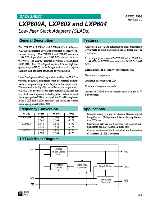
MHz for LXP604) is converted to 1.544 MHz CLKO. When SEL = Low, 1.544 MHz CLKI is converted to higher frequency CLKO (2.048 for LXP600A and LXP602, or 4.096 MHz for LXP604).
and to FSI (if FSI is provided).
ë
+)2 2 High Frequency Outputï HFO is used to derive CLKO. HFO can also clock external
devices. HFO is always a multiple of CLKO (CLKO x2, x3, or x4). Actual frequencies are determined by device, CLKI and CLKO frequencies and Mode Select (SEL) input, as listed in Table 2.
è
‡ 1R H[WHUQDO FRPSRQHQWV
‡ $YDLODEOH LQ åðSLQ SODVWLF ',3
ç
‡ 3LQðVHOHFWDEOH RSHUDWLRQ PRGH
‡ $GYDQFHG &026 GHYLFH UHTXLUHV RQO\ D VLQJOH òè 9 SRZHU VXSSO\
æ
å
$SSOLFDWLRQV
‡ ,QWHUQDO WLPLQJ V\VWHP IRU &KDQQHO %DQNVñ 'LJLWDO /RRS &DUULHUVñ 0XOWLSOH[HUVñ ,QWHUQDO 7LPLQJ *HQHUDð WRUVñ 3%;ñ HWFï
欧姆尼克 1000 系列电磁感应器说明书

Dimensions: [mm]749252070749252070BC749252070749252070T e m p e r a t u r eT pT L749252070Cautions and Warnings:The following conditions apply to all goods within the product series of WE-CST of Würth Elektronik eiSos GmbH & Co. KG:General:•This electronic component is designed and manufactured for use in general electronic equipment.•Würth Elektronik must be asked for written approval (following the PPAP procedure) before incorporating the components into any equipment in fields such as military, aerospace, aviation, nuclear control, submarine, transportation (automotive control, train control, ship control), transportation signal, disaster prevention, medical, public information network etc. where higher safety and reliability are especially required and/or if there is the possibility of direct damage or human injury.•Electronic components that will be used in safety-critical or high-reliability applications, should be pre-evaluated by the customer. •The component is designed and manufactured to be used within the datasheet specified values. If the usage and operation conditions specified in the datasheet are not met, the wire insulation may be damaged or dissolved.•Do not drop or impact the components, as the component may be damaged.•Würth Elektronik products are qualified according to international standards, which are listed in each product reliability report. Würth Elektronik does not warrant any customer qualified product characteristics beyond Würth Elektroniks’ specifications, for its validity and sustainability over time.•The responsibility for the applicability of the customer specific products and use in a particular customer design is always within the authority of the customer. All technical specifications for standard products also apply to customer specific products.Product specific:Soldering:•The solder profile must comply with the technical product specifications. All other profiles will void the warranty.•All other soldering methods are at the customers’ own risk.•Strong forces which may affect the coplanarity of the components’ electrical connection with the PCB (i.e. pins), can damage the component, resulting in avoid of the warranty.Cleaning and Washing:•Washing agents used during the production to clean the customer application might damage or change the characteristics of the wire insulation, marking or plating. Washing agents may have a negative effect on the long-term functionality of the product.•Using a brush during the cleaning process may break the wire due to its small diameter. Therefore, we do not recommend using a brush during the PCB cleaning process.Potting:•If the product is potted in the customer application, the potting material might shrink or expand during and after hardening. Shrinking could lead to an incomplete seal, allowing contaminants into the core. Expansion could damage the component. We recommend a manual inspection after potting to avoid these effects.Storage Conditions:• A storage of Würth Elektronik products for longer than 12 months is not recommended. Within other effects, the terminals may suffer degradation, resulting in bad solderability. Therefore, all products shall be used within the period of 12 months based on the day of shipment.•Do not expose the components to direct sunlight.•The storage conditions in the original packaging are defined according to DIN EN 61760-2.•The storage conditions stated in the original packaging apply to the storage time and not to the transportation time of the components. Packaging:•The packaging specifications apply only to purchase orders comprising whole packaging units. If the ordered quantity exceeds or is lower than the specified packaging unit, packaging in accordance with the packaging specifications cannot be ensured. Handling:•Violation of the technical product specifications such as exceeding the nominal rated current will void the warranty.•Applying currents with audio-frequency signals may result in audible noise due to the magnetostrictive material properties.•Due to heavy weight of the components, strong forces and high accelerations may have the effect to damage the electrical connection or to harm the circuit board and will void the warranty.•The temperature rise of the component must be taken into consideration. The operating temperature is comprised of ambient temperature and temperature rise of the component.The operating temperature of the component shall not exceed the maximum temperature specified.These cautions and warnings comply with the state of the scientific and technical knowledge and are believed to be accurate and reliable.However, no responsibility is assumed for inaccuracies or incompleteness.Würth Elektronik eiSos GmbH & Co. KGEMC & Inductive SolutionsMax-Eyth-Str. 174638 WaldenburgGermanyCHECKED REVISION DATE (YYYY-MM-DD)GENERAL TOLERANCE PROJECTIONMETHODCHC001.0032022-10-20DIN ISO 2768-1mDESCRIPTIONWE-CST Current SenseTransformer ORDER CODE749252070SIZE/TYPE BUSINESS UNIT STATUS PAGEImportant NotesThe following conditions apply to all goods within the product range of Würth Elektronik eiSos GmbH & Co. KG:1. General Customer ResponsibilitySome goods within the product range of Würth Elektronik eiSos GmbH & Co. KG contain statements regarding general suitability for certain application areas. These statements about suitability are based on our knowledge and experience of typical requirements concerning the areas, serve as general guidance and cannot be estimated as binding statements about the suitability for a customer application. The responsibility for the applicability and use in a particular customer design is always solely within the authority of the customer. Due to this fact it is up to the customer to evaluate, where appropriate to investigate and decide whether the device with the specific product characteristics described in the product specification is valid and suitable for the respective customer application or not.2. Customer Responsibility related to Specific, in particular Safety-Relevant ApplicationsIt has to be clearly pointed out that the possibility of a malfunction of electronic components or failure before the end of the usual lifetime cannot be completely eliminated in the current state of the art, even if the products are operated within the range of the specifications.In certain customer applications requiring a very high level of safety and especially in customer applications in which the malfunction or failure of an electronic component could endanger human life or health it must be ensured by most advanced technological aid of suitable design of the customer application that no injury or damage is caused to third parties in the event of malfunction or failure of an electronic component. Therefore, customer is cautioned to verify that data sheets are current before placing orders. The current data sheets can be downloaded at .3. Best Care and AttentionAny product-specific notes, cautions and warnings must be strictly observed. Any disregard will result in the loss of warranty.4. Customer Support for Product SpecificationsSome products within the product range may contain substances which are subject to restrictions in certain jurisdictions in order to serve specific technical requirements. Necessary information is available on request. In this case the field sales engineer or the internal sales person in charge should be contacted who will be happy to support in this matter.5. Product R&DDue to constant product improvement product specifications may change from time to time. As a standard reporting procedure of the Product Change Notification (PCN) according to the JEDEC-Standard inform about minor and major changes. In case of further queries regarding the PCN, the field sales engineer or the internal sales person in charge should be contacted. The basic responsibility of the customer as per Section 1 and 2 remains unaffected.6. Product Life CycleDue to technical progress and economical evaluation we also reserve the right to discontinue production and delivery of products. As a standard reporting procedure of the Product Termination Notification (PTN) according to the JEDEC-Standard we will inform at an early stage about inevitable product discontinuance. According to this we cannot guarantee that all products within our product range will always be available. Therefore it needs to be verified with the field sales engineer or the internal sales person in charge about the current product availability expectancy before or when the product for application design-in disposal is considered. The approach named above does not apply in the case of individual agreements deviating from the foregoing for customer-specific products.7. Property RightsAll the rights for contractual products produced by Würth Elektronik eiSos GmbH & Co. KG on the basis of ideas, development contracts as well as models or templates that are subject to copyright, patent or commercial protection supplied to the customer will remain with Würth Elektronik eiSos GmbH & Co. KG. Würth Elektronik eiSos GmbH & Co. KG does not warrant or represent that any license, either expressed or implied, is granted under any patent right, copyright, mask work right, or other intellectual property right relating to any combination, application, or process in which Würth Elektronik eiSos GmbH & Co. KG components or services are used.8. General Terms and ConditionsUnless otherwise agreed in individual contracts, all orders are subject to the current version of the “General Terms and Conditions of Würth Elektronik eiSos Group”, last version available at .Würth Elektronik eiSos GmbH & Co. KGEMC & Inductive SolutionsMax-Eyth-Str. 174638 WaldenburgGermanyCHECKED REVISION DATE (YYYY-MM-DD)GENERAL TOLERANCE PROJECTIONMETHODCHC001.0032022-10-20DIN ISO 2768-1mDESCRIPTIONWE-CST Current SenseTransformer ORDER CODE749252070SIZE/TYPE BUSINESS UNIT STATUS PAGE。
TPS604中文资料

SLVS324 - 2001年7月功能∙反转输入电压∙高达60 mA的输出电流∙只有三个小1 - μF陶瓷电容器的∙输入电压范围从1.6 V至5.5 V,∙省电模式在低输出电流(TPS60400),以提高效率∙器件的静态电流典型的100 μ∙综合活动肖特基二极管应用•LCD偏置∙砷化镓射频功率放大器的偏置∙便携式仪器在传感器电源∙双极放大器的电源∙医疗器械∙电池供电设备DBV封装(顶视图)CFLY +接地启动进入负载输出∙小型5引脚SOT23封装中•评估模块TPS60400EVM-178CFLY-描述TPS6040x是一个不受管制的负输出电压的输入电压范围从1.6 V至5.5 V的设备通常是由一个5 V或3.3 preregulated电源轨五,由于它的宽输入电压范围提供了设备产生的家庭,两个或三个镍镉电池,镍氢电池或碱性电池,以及一个锂离子电池功率他们还可以。
只有三个外部1 - μ F电容需要建立一个完整的电荷泵DC / DC逆变器。
5引脚SOT23封装,组装,完整的转换器,可建50毫米2的电路板面积。
额外的电路板面积和减少元件数量达到取代肖特基二极管通常需要启动到集成电路的负载。
TPS6040x可提供的最大输出电流60毫安的典型转换效率大于90%以上的宽输出电流范围。
20千赫,50千赫,250 kHz固定频率操作设备三个选项可供选择。
一个装置带有一个可变开关频率,以降低工作电流在一个宽负载范围内的应用,使价值低电容设计。
典型应用电路TPS6040 0的输出VOLTAG é V S 输入电压产量-1.6 V至-5V,最大60 mA至五Ø -输出电压- V的-1-2-3-4-5012345VI - 输入电压- V的请注意,一个重要的通知有关可用性,标准保修,并使用在关键应用德州仪器公司的半导体产品和免责条款及其出现在此数据表的结束。
版权所有© 2001年,德州仪器生产数据信息是当前出版日期。
IEC 中文翻译
光伏(PV)组件安全鉴定:第2 部分:试验要求1 范围和目标IEC 61730 的本部分规定了光伏组件的试验要求,以使其在预期的使用期内提供电气安全和机械运行。
对由机械或外界环境应力造成的电击、火灾和人身伤害的保护措施进行评估。
IEC 61730-1 给出了结构要求,本部分主要描述测试要求。
本部分试图定义不同应用等级的光伏组件基本要求,但是不可能满足所有国家和地区的要求。
本部分未涵盖海上及交通工具应用时的特殊要求。
本部分也不适用于集成了逆变器的组件(交流组件)。
本部分设计的试验顺序与IEC 61215 或IEC 61646 相一致,所以一套样品可同时用于光伏组件设计的安全和性能评估。
本部分所设计的试验顺序使得IEC 61215 或IEC 61646 可作为基本的预处理试验。
注1:本部分要求的试验顺序可能不适用于所有可能情况的光伏组件应用情况的相关安全。
本部分标准采用了编辑本标准试验的最佳顺序。
有一些出版物,比如在高电压系统中由于组件破损而引起电击的潜在危险,应标注有系统设计,应用场所,限制接近等级以及维护等。
本部分的目的是为已通过IEC 61730-1 的光伏组件提供安全鉴定的试验要求。
这些要求是为了减少由于组件应用等级误用、错误使用或内部元件碎裂而引起的火灾、电击和人身伤害。
本部分规定了为提供组件基本安全试验要求和附加的试验。
测试范围包括外观检查、电击、火灾、机械应力和环境应力。
注2:除本部分的要求外,应考虑ISO 相关的标准、国家和地区法规中另外的试验要求。
这些法规对组件在当地的安装和使用具有管辖权。
2 规范性引用文件下列文件中的条款在本部分规定中引用。
凡是注日期的引用文件,只有相应的版本适合本部分。
凡是不注日期的引用文件,其最新的版本均适用于本部分。
IEC 60060—1、高压试验技术--第1部分:一般定义和试验要求IEC 60068—1、环境试验第1部分:总则和指南IEC 60410、计数检查抽样方案和程序IEC 60664—1:1992、低压系统内设备的绝缘配合.第1部分:原则、要求和试验修订2(2002)IEC 60904—2、光伏器件第2部分:标准太阳电池的要求IEC 60904—6、光伏器件第6部分:标准太阳电池组件的要求IEC 61032:1997、使用防护外罩保护人和设备--校验用探针IEC 61140、电击防护设备:装置和设备的通用方位IEC 61215:2004、地面用晶体硅光伏组件—设计鉴定和定型IEC 61646:1996、地面用薄膜光伏组件设计鉴定和定型IEC61730—1:2004、光伏(PV) 组件安全合格鉴定.第1部分:施工要求ISO/IEC 17025、检测和校准实验室能力的通用要求ANSI/UL 514C、非金属出线盒、嵌入式器件盒和外壳ANSI/UL 790、屋顶层材料防火试验的安全性标准ANSI/UL 1703、平面光伏电池板ANSI Z97.1、美国国家标准:建筑物中窗用玻璃的安全性能规范和测试方法3 应用等级3.1 概述光伏组件可以有许多不同的应用方式,因此把评估在相应应用条件下的潜在危险与组件结构联系起来考虑是很重要的,不同的应用等级应该满足与其相应的安全要求和进行必要的试验。
常用纽扣电池对照表之欧阳语创编
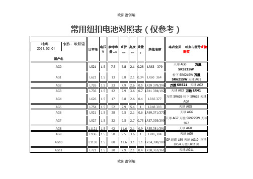
AG9
L936
1.5
50
9.5
3.6
1
LR45,394
天球AG9
AG10
L1130
1.5
80
11.6
3.1
1.1
LR54,390/189
GP超霸189天球AG10南孚LR54万胜LR1130
AG11
L721
1.5
20
7.9
2.1
0.4
LR58,362/361
天球AG11
AG12
L1142
1.5
松下SR621SW万胜SR621SW天球AG1
AG2
L726
1.5
23
7.9
2.6
0.5
LR59 379/396
万胜SR521天球AG2
AG3
L736
1.5
42
7.9
3.6
0.7
LR41 384/192
天球AG3万胜LR41
AG4
L626
1.5
17
6.8
2.6
0.4
LR66 377
万胜SR626松下SR626天球AG4
96
11.6
4.2
1.6
LR43,301/186
GP超霸186天球AG11万胜LR43
AG13
L1154
1.5
160
11.6
5.4
2
LR44,A76/357
GP超霸A76南孚A76天球AG13万胜LR44
松下SR44白象LR44
SR616
1.55
19
6.8
1.6
0.3
321
松下SR616万胜321
AE-6041电动机保护测控装置技术及使用说明书
AE-6041电动机保护测控装置技术及使用说明书1. 概述AE-6041电动机测控保护装置(以下简称装置),主要适应于6KV-66KV 电压等级的电动机。
主要功能保护功能:a) 速断保护b) 启动时间过长保护(过流I 段)c) 堵转保护(过流II 段)d) 过电压保护e) 低电压保护f) 定时限负序过流保护g) 反时限负序过流保护h) 热过负荷保护i) 接地保护j )过温保护遥测功能:三相电流、三相电压、三线电压、频率,功率、功率因数、零序电流、零序电压、正序电流、负序电流。
遥控功能:断路器分合闸,装置信号复归,保护软压板投退遥信功能:8 路遥信开入量其它:网络对时和手动对时功能全隔离RS-485 通讯接口,国际标准ModBUS-RTU 通讯协议2. 技术数据AC 输入电流额定5A:15A 连续;短时250A 1 秒极限动态范围:625A 持续1 周波(正弦波)功耗:5A 时0.16VA, 15A 时1.15VA额定1A:3A 连续;短时100A 1 秒极限动态范围:250A 持续1 周波(正弦波)功耗:1A 时0.06VA,3A 时1.18VA 输出接点符合IEC 255-0-20:1974,采用简单评估法5A 持续30A 接通符合IEEC C37.90:1989100A 持续1 秒启动/返回时间:<5ms分断能力(L/R = 40ms):24V 0.75A 10,000次48V 0.50A 10,000次125V0.30A10,000次250V0.20A10,000次循环能力( L/R40ms):24V0.75A每秒2.5 次48V0.50A每秒2.5 次125V0.30A每秒2.5 次250V0.20A每秒2.5 次光隔输入在额定控制电压下,每个光隔输入的电流为5mA 。
额定电源110伏:88 - 132Vdc或88 T21Vac220 伏:176 - 264Vdc 或176 - 242Vac额定5.5 瓦, 最大8.5 瓦例行绝缘试验电流输入端:500Vac 60秒不小于10M电源、光隔输入及输出接点:500Vac 60秒不小于10M带CE 标志的装置进行下列IEC255-5: 1 977 绝缘测试;模拟输入:500Vac 60秒不小于10M电源、光隔输入及输出接点:500Vac 60秒不小于10M工作温度-10 C 〜+55C( +14°F〜+ 131°F)。
艾特顿 199160 商品说明说明书
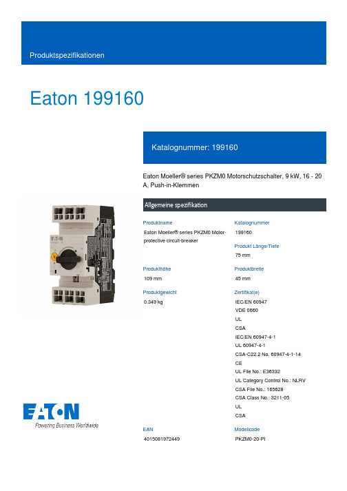
Eaton 199160Eaton Moeller® series PKZM0 Motorschutzschalter, 9 kW, 16 - 20 A, Push-in-KlemmenAllgemeine spezifikationEaton Moeller® series PKZM0 Motor-protective circuit-breaker19916075 mm109 mm 45 mm 0.349 kgIEC/EN 60947 VDE 0660 UL CSAIEC/EN 60947-4-1 UL 60947-4-1CSA-C22.2 No. 60947-4-1-14 CEUL File No.: E36332UL Category Control No.: NLRV CSA File No.: 165628 CSA Class No.: 3211-05 UL CSA4015081972449PKZM0-20-PIProduktnameKatalognummer Produkt Länge/Tiefe Produkthöhe Produktbreite Produktgewicht Zertifikat(e)EANModellcodeDrehknopfPhasenausfallempfindlichkeit (gemäß IEC/EN 60947-4-1, VDE 0660 Teil 102)MotorschutzPhasenausfallempfindlich3-polig 100.000 Schaltvorgänge100.000 SchaltvorgängeHutschienenmontage optionalAufschnappbar auf Hutschiene IEC/EN 60715 mit 7,5 oder 15 mm Höhe.40 Schaltspiele/hIII3MotorschutzschalterFinger- und handrückensicher, Berührungsschutz bei senkrechter Betätigung von vorne (EN 50274)6000 V AC25 g, Mechanisch, entsprechend IEC/EN 60068-2-27, Halbsinusstoß 10 msAuch Motoren mit Effizienzklasse IE3Nebenstromkreis: Manueller Typ E bei Einsatz mit Klemme, oder geeignet für Gruppeninstallationen, (UL/CSA)≤ 0,25 %/K, Restfehler für T > 40°-25 - 55 °C, Arbeitsbereich-5 - 40 °C gemäß IEC/EN 60947, VDE 0660Motorstarterkombinationen Typ MSC…Stellgliedtyp Merkmale Funktionen Polzahl Lebensdauer, elektrischLebensdauer, mechanisch MontagemethodeEinbaulageBetriebsfrequenzÜberspannungskategorie VerschmutzungsgradProduktkategorieSchutzBemessungsstoßspannungsfestigkeit (Uimp) SchockfestigkeitGeeignet fürTemperaturkompensationVerwendet mitMax. 2000 m-25 °C55 °C25 °C40 °C40 °C80 °CFeuchte Wärme, zyklisch, nach IEC 60068-2-30 Feuchte Wärme, konstant, nach IEC 60068-2-781 x (1 - 6) mm²18 - 812 mm50 Hz60 Hz20 A5.5 kW9 kW690 V690 V20 A18 kA, 240 V, SCCR (UL/CSA) mit Leistungsschütz DILM25 18 kA, 480 Y/277 V, SCCR (UL/CSA) mit Leistungsschütz DILM25310 A, Irm, Einstellbereich max.± 20% Toleranz, AuslöserblöckeGrundgerät befestigt 15,5 x lu, Auslöserblöcke 1.5 HP 5 HP 3 HP 15 HPHöheUmgebungsbetriebstemperatur – min Umgebungsbetriebstemperatur – max Umgebungsbetriebstemperatur (gekapselt) – min Umgebungsbetriebstemperatur (gekapselt) – max Umgebungstemperatur Lagerung - min Umgebungstemperatur Lagerung - max Klimafestigkeit Anschlusskapazität (feindrähtig)Anschlusskapazität (ein-/mehrdrähtig AWG)Abisolierlänge (Hauptleiter)Bemessungsfrequenz - minBemessungsfrequenz - max Bemessungsbetriebsstrom (Ie) Bemessungsbetriebsleistung bei AC-3, 220/230 V, 50 Hz Bemessungsbetriebsleistung bei AC-3, 380/400 V, 50 Hz Bemessungsbetriebsspannung (Ue) - min Bemessungsbetriebsspannung (Ue) - max Bemessungsdauerstrom (Iu)Bemessungskurzschlussstrom (Typ E) Kurzschlussauslöser Zugeor. Motorleist. b. 115/120 V, 60 Hz, 1-phasig Zugeordnete Motorleistung bei 200/208 V, 60 Hz, 3-phasig Zugeordnete Motorleistung bei 230/240 V, 60 Hz, 1-phasig Zugeordnete Motorleistung bei 575/600 V, 60 Hzm 3-phasigPush-In Klemmen020 A20 AÜberlastauslöser: Auslöseklasse 10 A 5.82 W0 W0 W0 WAnforderungen der Produktnorm sind erfüllt.Anforderungen der Produktnorm sind erfüllt.Anforderungen der Produktnorm sind erfüllt.Anforderungen der Produktnorm sind erfüllt.Anforderungen der Produktnorm sind erfüllt.Unzutreffend, da die gesamten Schaltgeräte überprüft werden müssen.Unzutreffend, da die gesamten Schaltgeräte überprüft werden müssen.Anforderungen der Produktnorm sind erfüllt.Verbindung Anzahl der Hilfskontakte (Wechsler)Anzahl der Hilfskontakte (Öffner)Anzahl Hilfskontakte (Schließer)Überlastauslösestromeinstellung - min Überlastauslösestromeinstellung - max Auslösecharakteristik Geräteverlustleistung, stromabhängig pvid Verlustleistungskapazität PdissVerlustleistung pro Pol, stromabhängig, PvidStatische Verlustleistung, stromunabhängig PVS10.2.2 Korrosionsbeständigkeit10.2.3.1 Wärmebeständigkeit von Umhüllung10.2.3.2 Widerstandsfähigkeit Isolierstoffe gewöhnliche Wärme 10.2.3.3 Widerst. Isolierstoffe abnorm. Wärme/Feuer durch int. elektr. Auswirk.10.2.4 Beständigkeit gegen UV-Strahlung10.2.5 Heben10.2.6 Schlagprüfung10.2.7 BeschriftungenUnzutreffend, da die gesamten Schaltgeräte überprüft werden müssen.Anforderungen der Produktnorm sind erfüllt.Unzutreffend, da die gesamten Schaltgeräte überprüft werden müssen.Unzutreffend, da die gesamten Schaltgeräte überprüft werden müssen.Liegt in der Verantwortung des Schaltanlagenbauers.Liegt in der Verantwortung des Schaltanlagenbauers.Liegt in der Verantwortung des Schaltanlagenbauers.Liegt in der Verantwortung des Schaltanlagenbauers.Liegt in der Verantwortung des Schaltanlagenbauers.Die Erwärmungsberechnung liegt in der Verantwortung des Schaltanlagenbauers. Eaton stellt Verlustleistungsdaten der Geräte bereit.Liegt in der Verantwortung des Schaltanlagenbauers. Die Spezifikationen für die Schaltgeräte müssen beachtet werden.Liegt in der Verantwortung des Schaltanlagenbauers. Die Spezifikationen für die Schaltgeräte müssen beachtet werden.Das Gerät erfüllt die Anforderungen, wenn die Informationen in der Montageanweisung (IL) beachtet werden.DA-DC-00004889.pdfDA-DC-00004919.pdfETN.PKZM0-20-PI.edzIL122024ZUWIN-WIN mit Push-in-TechnikProduktübersicht für den Maschinenbau Sortimentskatalog Motoren schalten und schützenpkzm0_pi.stpmotorschutzschalter_bis_32a_pi.dwgeaton-manual-motor-starters-pkz-dimensions.epseaton-manual-motor-starters-pkz-dimensions-002.eps eaton-manual-motor-starters-pkzm-pkzm0-dimensions.eps 121X042121X00210.3 Schutzart von Baugruppen10.4 Luft- und Kriechstrecken10.5 Schutz gegen elektrischen Schlag10.6 Einbau von Betriebsmitteln10.7 Innere Stromkreise und Verbindungen10.8 Anschlüsse für von außen eingeführte Leiter 10.9.2 Betriebsfrequente Spannungsfestigkeit 10.9.3 Stoßspannungsfestigkeit10.9.4 Prüfung von Umhüllungen aus Isolierstoff 10.10 Erwärmung10.11 Kurzschlussfestigkeit10.12 Elektromagnetische Verträglichkeit10.13 Mechanische Funktion Declarations of conformity eCAD model Installationsanleitung Installationsvideos KatalogemCAD model ZeichnungenEaton Konzern plc Eaton-Haus30 Pembroke-Straße Dublin 4, Irland © 2023 Eaton. Alle Rechte vorbehalten. Eaton ist eine eingetrageneMarke.Alle anderen Warenzeichen sindEigentum ihrer jeweiligenBesitzer./socialmedia。
说说ECH-604 系列

说说ECH-604系列1、适用于中央空调冷冻水(热水)系统化学水处理设备型号:ECH-B-604全自动智能控制在线加药保障系统系统主要部件:1、全自动智能控制系统2、隔膜计量泵3、加药桶4、污垢热阻在线监测仪(选用)(中国国家发明专利)5、水质参数在线监测仪电导率在线控制仪 PH值在线监测仪(选用)药剂浓度监测仪(选用)腐蚀实时在线监测仪(中国国家发明专利)6、电磁排污阀(选用)7、脉冲流量仪(选用)2、适用于中央空调冷却水系统化学水处理加药设备型号:ECH-A-604全自动智能控制在线加药保障系统系统主要部件:1、全自动智能控制系统2、隔膜计量泵3、加药桶4、污垢热阻在线监测仪(选用)5、水质参数在线监测仪电导率在线控制仪 PH值在线监测仪(选用)药剂浓度监测仪(选用)腐蚀实时在线监测仪6、电磁排污阀(选用)7、脉冲流量仪(选用)3、适用于锅炉水系统化学水处理加药设备型号:ECH-C-604全自动智能控制在线加药保障系统系统主要部件:1、全自动智能控制系统2、隔膜计量泵3、加药桶4、全自动软化水处理器5、水质参数在线监测仪电导率在线控制仪 PH值在线监测仪(选用)溶解氧在线(选用)6、冷却取样器(选用)7、脉冲流量仪(选用)4、适用于游泳池水系统水处理加药设备型号 ECH-D-604全自动智能控制在线加药保障系统系统主要部件:1、全自动智能控制系统2、隔膜计量泵3、加药桶(消毒剂及PH值调节剂)4、余氯在线监测仪5、PH值监测仪(选用)5、适用于中水加用水系统水处理加药设备型号 ECH-F-604全自动智能控制在线加药加药保障系统设备型号 ECH-F-604全自动智能控制抑制性乙二醇补加系统设备主要部件1、ECH-608B PLC全自动智能系统(装与控制箱内,含ECH-661大型数据软件系统)2、ECH-608H1 乙二醇储存系统(含输出、控制信号)3、ECH-608H2 混合系统(含输出、控制信号)4、ECH-608H3 中间系统(含输出、控制信号)5、ECH-608H4 全自动定压补水系统(含输出、控制信号)6、ECH-608G1 定压泵(一用一备,Q=5t,H=60m)2台7、ECH-608G2 输送泵(Q=5t,H=15m) 2台8、电磁阀 4只9、其他配件6、适用于污水系统水处理加药设备型号 ECH-D-604全自动智能控制在线加药保障系统系统主要部件:1、PLC控制2、隔膜计量泵3、加药桶4、水质参数在线监测仪(含四部分)PH值在线监测仪(选用)药剂浓度监测仪(选用)余氯在线监测仪(选用)COD在线仪(选用)各型加药设备尺寸占地面积参考数据表配置类型加药桶型号安装尺寸(长宽高)适用于循环水量一泵一桶 180L 600×600×1200 5000m3/h 500L 900×900×1500 20000m3/h二泵二桶 1000L 300×1220×1500 30000m3/h 180L 1400×1400×1300 5000m3/h500L 2000×1600×1500 20000m3/h三泵三桶 1000L 2600×1800×1600 30000m3/h 180L 2050×1400×1300 5000m3/h500L 2800×1600×1500 20000m3/h1000L 3900×1800×1600 30000m3/h说明:加药装置结构自动控制装置主要由自动控制柜、记录仪、交流电机、加药泵等组成。
E2EL-X10F12M中文资料(omron)中文数据手册「EasyDatasheet - 矽搜」
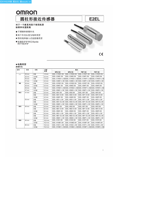
E2EL–X4E1–DL 2M E2EL–X4E2–DL 2M E2EL–X4F1–DL 2M E2EL–X4F2–DL 2M
E2EL–X4ME1–L 2M E2EL–X4ME2–L 2M E2EL–X4MF1–L 2M E2EL–X4MF2–L 2M
Байду номын сангаас
E2EL–X5E1 2M E2EL–X5E2 2M E2EL–X5F1 2M E2EL–X5F2 2M
E2EL–X4E1–D 2M E2EL–X4E2–D 2M E2EL–X4F1–D 2M E2EL–X4F2–D 2M
E2EL–X4ME1 2M E2EL–X4ME2 2M E2EL–X4MF1 2M E2EL–X4MF2 2M
E2EL–X2E1–L 2M E2EL–X2E2–L 2M E2EL–X2F1–L 2M E2EL–X2F2–L 2M
1
芯片中文手册,看全文,戳
E2EL
不锈钢外壳
直径
长度
6,5 30 mm 45 mm
M8 30 mm 45 mm
M12 41 mm 53 mm
M18 40 mm 73 mm
插头类型
黄铜外壳
直径 /
触点
长度
6,5 / 插头 M8
M8 / 插头 M8
M8 / 插头 M12
M12 / 插头 M12
45 mm 47 mm 54 mm 56 mm 45 mm 47 mm 54 mm 56 mm 44 mm 46 mm 60 mm 62 mm 49 mm
60 mm
M18 / 53 mm 插头 M12
80 mm
M30 / 插头 M12
55 mm 80 mm
不锈钢外壳
直径 /
iec 60404-3—2010
IEC xxx-3—2010 是国际电工委员会(International Electrotechnical Commission,简称IEC)下的标准之一,是关于不同类型磁性材料的一致标准规范。
本文将对该标准的主要内容进行介绍,并探讨其在工程实践中的应用。
一、标准的背景与意义IEC xxx-3—2010 标准是磁性材料领域的一项重要规范,它为不同类型的磁性材料提供了统一的测试方法和技术要求。
作为全球范围内的统一标准,IEC xxx-3—2010 的制定旨在提高磁性材料的质量和性能,并促进国际间的技术交流和合作。
通过该标准的实施,能够有效减少各地各家生产厂家之间因技术标准不统一而导致的交流障碍和信息不对称,进而有利于推动磁性材料行业的持续发展和进步。
二、标准的内容和主要技术要求IEC xxx-3—2010 标准主要包括以下几个方面的内容和技术要求:1. 术语和定义:对磁性材料领域中常用的术语和定义进行了规范和解释,以便在标准的实施过程中能够达成共识,减少术语误解和交流困难。
2. 符号和标记:规定了磁性材料在生产、使用和销售过程中所应使用的符号和标记,有利于统一行业标准,提高产品识别和交流效率。
3. 测量方法:详细介绍了对不同类型磁性材料的磁性能参数进行测量和测试的方法和技术要求,包括磁化曲线的测量、磁滞回线的测量、铁磁材料的磁化强度测量等。
4. 技术要求:针对不同类型的磁性材料,规定了其在磁化性能、磁化损耗、磁滞回线等方面的技术要求和限制值,以确保其符合国际标准和行业规范。
三、标准的应用和推广IEC xxx-3—2010 标准作为国际电工委员会下的一项重要规范,在全球范围内得到了广泛的应用和推广。
该标准为生产厂家提供了统一的测试方法和技术要求,使得不同厂家生产的磁性材料可以进行公正的比较和评价,有效提升了产品质量和性能。
IEC xxx-3—2010 的实施有助于促进国际间的技术交流和合作,推动磁性材料行业的全球化发展。
Omega DFG60 Series数字力挠仪用户指南说明书
e-mail:**************DFG60 SERIESDigital Force GaugeServicing North America:USA:One Omega Drive, Box 4047ISO 9001 CertifiedStamford, CT 06907-0047TEL: (203) 359-1660FAX: (203) 359-7700e-mail:**************Canada:976 BergarLaval (Quebec) H7L 5A1TEL: (514) 856-6928FAX: (514) 856-6886e-mail:****************For immediate technical or application assistance:USA and Canada:Sales Service: 1-800-826-6342 / 1-800-TC-OMEGA ®Customer Service: 1-800-622-2378 / 1-800-622-BEST ®Engineering Service: 1-800-872-9436 / 1-800-USA-WHEN ®TELEX: 996404 EASYLINK: 62968934 CABLE: OMEGA Mexico:TEL: (001) 800-826-6342FAX: (001) 203-359-7807En Espan ˜ol: (001) 203-359-7803e-mail:*******************************.mxServicing Europe:Benelux:Postbus 8034, 1180 LA Amstelveen, The Netherlands TEL: +31 (0)20 6418405FAX: +31 (0)20 6434643Toll Free in Benelux: 0800 0993344e-mail:************Czech Republic:Rudé armády 1868, 733 01 Karviná 8TEL: +420 (0)69 6311899FAX: +420 (0)69 6311114Toll Free in Czech Republic: 0800-1-66342e-mail:***************France:9, rue Denis Papin, 78190 Trappes TEL: +33 (0)130 621 400FAX: +33 (0)130 699 120Toll Free in France: 0800-4-06342e-mail:****************Germany/Austria:Daimlerstrasse 26, D-75392 Deckenpfronn, GermanyTEL: +49 (0)7056 3017FAX: +49 (0)7056 8540Toll Free in Germany: 0800 TC-OMEGA SMe-mail:*****************United Kingdom:One Omega Drive, River Bend Technology Centre ISO 9002 CertifiedNorthbank, Irlam, Manchester M44 5EX, EnglandTEL: +44 (0)161 777 6611FAX: +44 (0)161 777 6622Toll Free in England: 0800 488 488e-mail:**************.ukOMEGAnet SMOn-Line Service Internet e-mail http://***************************It is the policy of OMEGA to comply with all worldwide safety and EMC/EMI regulations thatapply. OMEGA is constantly pursuing certification of its products to the European New Approach Directives. OMEGA will add the CE mark to every appropriate device upon certification.The information contained in this document is believed to be correct but OMEGA Engineering, Inc. accepts no liability for any errors it contains, and reserves the right to alter specifications without notice.WARNING: These products are not designed for use in, and should not be used for, patient connected applications.GENERAL OPERATION1Press .The capacity of the gauge is displayed and the gauge will automatically enter into the measuring mode.Press and hold for at least four (4) seconds each time you wish to selectbetween pounds (ounces),kilograms (grams) and Newtons.2Hand tighten(no tool!) selected attachment to the measuring shaft.3When the gauge is turned on,it will go directly to its real time measuring mode.Press to mea-sure peak forces.“Peak icon”on the display indicates peak measuring mode,whereas the peak read-ing will not change until a higher value is measured.To delete the last peak reading,press .Toend peak reading mode and go to real time measuring mode,press again.real time mode display peak mode display4If necessary,press to tare the weight of the attachment and shaft orientation.Pressing will also clear the peak reading.5Make sure to apply tension and compression (-) forces to the gauge in linewith the measuring shaft.DO NOT attempt to measure forces at an angle tothe measuring shaft - damage to load cell and/or shaft may result.PRECAUTIONS1!REGARDLESS of whether the unit is ON or OFF,do not exceed the capacity of the gauge.At 105% of the rated capacity,the display will flash.Never exceed 200% of the rated capacity, or the load cell will be damaged.2When mounting,use M4 mounting screws with a maximum insertion depth of 5 mm into the gauge. 3Measure in line tension and compression forces only.Do not attempt to measure forces at an angle to the measuring shaft - damage to load cell and/or shaft may result.4Hand tighten attachments only.Do not use tools.5Make sure this gauge and all peripherals are powered down before attaching any cables.6Do not remove the warranty seal or disassemble the gauge.Disassembly voids warranty. RECHARGING NI-CAD BATTERY1To maximize the life of the battery,power will automatically shut off after 10 minutes of non-use.This automatic shut off feature can be bypassed and the gauge may be used continuously when the AC adapter/charger is used.2“BATT”icon will flash when gauge needs to be recharged.To maximize battery life,do not recharge until “BATT”icon flashes.With proper recharging,battery canbe recharged500 times.3Push to turn off power.Use the provided adapter/charger exclusively and plug into the correct AC output.It takes 8 hours to charge fully.4When the gauge is turned off,make sure the AC adapter/charger is disconnected to avoid overcharging.Press and holdfor 4 seconds to select newtons,ounces/pounds, or grams/kilograms. Release, press and hold for each unit change.Measuring Shaft Attach any of the sup-plied standard attach-ments or optional special attachments to measure tension or compression forces.Peak Icon peak hold is activated.Tension Icon Battery Icon Flashes when gaugeneeds to be recharged.PowerPower ON/OFF:When pressed, the capacity is displayed.After 10 minutes, unit will power down if nokey is pressed.COMMUNICATIONS PORTThe standard outputs of RS-232C and ±1 VDC analog allow you to capture data and SPC as well as peripher-al control of all keypad functions.Charger PortRecharge the internal battery or run from external source. Eight hours is required to fully recharge.PORT PIN ASSIGNMENTS1RS-232C and Digimatic Ground 2RS-232C Transmit Data 3Analog Output (±1VDC)4Digimatic Data Request 5RS-232C Receive Data 6Analog Ground 7Digimatic Clock8Digimatic Transmit DataCOMMAND*FUNCTION RESPONSEK [CR]Select “kg” units N [CR]Select “N” unitsL [CR]Select “lb” unitsO [CR]Select “oz” units(DPS - 0.5 and DPS - 1 only)R [CR] executed P [CR]Select peak mode E [CR] errorT [CR]Select real time mode Z [CR]Tare display Q [CR]Turn off powerD [CR]Transmit display data[value] [units] [mode] [CR]RS232 COMMAND/RESPONSE [mode] = T: Real time, P: Peak[units] = K: Kg, N: Newtons, L: Pounds, O: Ounces1RS-232C bi-directional interface functionsAll gauge functions can be duplicated from a remote location by utilizing RS-232C interface.All com-mands must be sent in uppercase ASCII character format followed by a carriage return (CR).Signal level:RS-232C Data bits:8 bits Stop bits: 1 bit Parity bits:NoBaud Rate:2400 bps 2±1 VDC ANALOG SIGNALConnect the CB-101 analog cable to the communications port and the device receiving the data.Accuracy± 0.2% F.S. ± 1 LSDSelectable Units Pounds/Ounces, Grams/Kilograms or Newtons Overload Capacity 200% of F.S. Display flashes beyond 105% of F.S.Display Update 20 times/secondPowerRechargeable NiCad battery pack or AC adapter Low Battery Indicator Display flashes BAT when battery is low CPU8-bit C-MOSA/D Converter 13-bit Delta Sigma systemOutputsRS-232 and ±1 VDC analog output Operating Temperature 30° to 100°F (0° to 40°C)Display 4-digit LCD Weight20 oz.Shipping Weight 4 lbs.Output PortRS232C:full duplex, 2400 baud, 8 databits, no paritybit, 1-stop bit.Analog: ±1VDC Included AC adapter/chargerAccessories6 attachments: hook, flat tip, conical tip, chisel tip, notched tip, extension shaftModelCapacity (Resolution)Pounds Kilograms Newtons OuncesGrams DFG60-0.58.819 oz (0.001 oz)250.0 g (0.1 g) 2.452 N (0.001 N)DFG60-117.64 oz (0.01 oz)500.0 g (0.1 g)4.903 N (0.001 N)DFG60-4 4.409 lb (0.001 lb) 2.000 kg (0.001 kg)19.61 N (0.01 N)DFG60-1111.02 lb (0.01 lb)5.000 kg (0.001 kg)49.03 N (0.01 N)DFG60-4444.09 lb (0.01 lb)20.00 kg (0.01 kg)196.1 N (0.01 N)DFG60-110110.2 (0.1 lb)50.00 kg (0.01 kg)490.3 N (0.1 N)DFG60 Ranges (Resolution) ± 0.2% F.S. ± 1 LSDDFG60 SPECIFICATIONSNote: Use an “R” suffix for reverse display units (for use on vertical test stand)DIMENSIONSOPTIONAL CABLESAnalog cable (10')CB-101RS-232C cable (10')9 pin female CB-203RS-232C Cable (10')25 pin maleCB-202Direct all warranty and repair requests/inquiries to the OMEGA Customer Service Department. BEFORE RETURNING ANY PRODUCT(S) TO OMEGA, PURCHAS ER MUS T OBTAIN AN AUTHORIZED RETURN (AR) NUMBER FROM OMEGA’S CUS TOMER S ERVICE DEPARTMENT (IN ORDER TO AVOID PROCESSING DELAYS). The assigned AR number should then be marked on the outside of the return package and on any correspondence.The purchaser is responsible for shipping charges, freight, insurance and proper packaging to prevent breakage in transit.FOR WARRANTY RETURNS, please have the following information available BEFORE contacting OMEGA:1.P.O. number under which the product wasPURCHASED,2.Model and serial number of the product underwarranty, and3.Repair instructions and/or specific problemsrelative to the product.FOR NON-WARRANTY REPAIRS,consult OMEGA for current repair charges. Have the following information available BEFORE contacting OMEGA: 1. P.O. number to cover the COSTof the repair,2.Model and serial number of product, and3.Repair instructions and/or specific problemsrelative to the product.OMEGA’s policy is to make running changes, not model changes, whenever an improvement is possible. This affords our customers the latest in technology and engineering.OMEGA is a registered trademark of OMEGA ENGINEERING, INC.© Copyright 1996 OMEGA ENGINEERING, INC. All rights reserved. This document may not be copied, photocopied, reproduced, translated, or reduced to any electronic medium or machine-readable form, in whole or in part, without prior written consent of OMEGA ENGINEERING, INC.Where Do I Find Everything I Need for Process Measurement and Control?OMEGA…Of Course!TEMPERATUREⅪߜThermocouple, RTD & Thermistor Probes, Connectors, Panels & AssembliesⅪߜWire: Thermocouple, RTD & ThermistorⅪߜCalibrators & Ice Point ReferencesⅪߜRecorders, Controllers & Process MonitorsⅪߜInfrared PyrometersPRESSURE, STRAIN AND FORCEⅪߜTransducers & Strain GaugesⅪߜLoad Cells & Pressure GaugesⅪߜDisplacement TransducersⅪߜInstrumentation & AccessoriesFLOW/LEVELⅪߜRotameters, Gas Mass Flowmeters & Flow ComputersⅪߜAir Velocity IndicatorsⅪߜTurbine/Paddlewheel SystemsⅪߜTotalizers & Batch ControllerspH/CONDUCTIVITYⅪߜpH Electrodes, Testers & AccessoriesⅪߜBenchtop/Laboratory MetersⅪߜControllers, Calibrators, Simulators & PumpsⅪߜIndustrial pH & Conductivity EquipmentDATA ACQUISITIONⅪߜData Acquisition & Engineering SoftwareⅪߜCommunications-Based Acquisition SystemsⅪߜPlug-in Cards for Apple, IBM & CompatiblesⅪߜDatalogging SystemsⅪߜRecorders, Printers & PlottersHEATERSⅪߜHeating CableⅪߜCartridge & Strip HeatersⅪߜImmersion & Band HeatersⅪߜFlexible HeatersⅪߜLaboratory HeatersENVIRONMENTALMONITORING AND CONTROLⅪߜMetering & Control InstrumentationⅪߜRefractometersⅪߜPumps & TubingⅪߜAir, Soil & Water MonitorsⅪߜIndustrial Water & Wastewater TreatmentⅪߜpH, Conductivity & Dissolved Oxygen InstrumentsM3513/1099。
e 604 商品说明书

e 604 Instruction manualDelivery includes Delivery includes• e 604• MZH 604 microphone clamp• pouch• quick guide• safety guideProduct overview1. Sound inlet basket2. XLR-3 connector3. Microphone clampInstallationInstallationAttaching the microphoneFasten the holder to the microphone using the screw.Connecting the microphoneConnect the XLR-3 socket of the microphone cable (optional accessories) to the XLR-3 socket of the microphone.OperationOperationPositioning the microphone on a drumUse the microphone clamp to attach the e 604 to the rim of the drum.Position the microphone on the drum so that it is 3 to 5 cm above the drumhead.3 – 5 cm(1.2 – 2")It is vital to observe the following notes:Position Resulting sound CommentaryA More fundamental Little overtones Position on the drum:3 t o 5 cm above the drumskinThe fundamental to overtones ratio can be adjus-ted by changing the angle of the microphone. The most balanced results are obtained at an angle of 30 t o 60°.BLess fundamental Many overtonesCUse of a second e 604 for picking up the bottom of the drumskin and the snares.NB: The lower microphone must be phase-rever-sed to avoid phase-cancellation effects due to the second microphone being on the other side of thedrumskin.A B CCleaning and maintaining the e 604Positioning the monitor loudspeakersTo prevent feedback and crosstalk, postion your monitor loudspeakers in the angle area of the highest cancellation of the microphone (approx. 135°).Cleaning and maintaining the e 604CAUTIONLIQUIDS CAN DAMAGE THE ELECTRONICS OF THE PRODUCT!Liquids entering the housing of the product can cause a short-circuit and damage the electronics.Keep all liquids away from the product.Do not use any solvents or cleansing agents.Disconnect the products from the power supply system and remove rechargeable batteries andbatteries before you begin cleaning.Clean all products only with a soft, dry cloth.SpecificationsSpecificationsTransducer principle dynamic Frequency response 40 - 18,000 H z Pick-up patterncardioid Sensitivity (free field, no load) 1.8 mV/Pa Nominal impedance (at 1 kHz)350 ΩMin. terminating impedance 1 kΩConnector XLR-3Dimensions Ø 33 mm, length 59 mm Weight60 gPolar pattern125 Hz 250 Hz 500 Hz 1,000 Hz 2,000 Hz 4,000 Hz8,000 Hz 16,000 Hz30°0°180°150°120°60°90°0510152025dB30°0°180°150°120°60°90°Frequency responsedBV50100200501,0002,0005,0010,00020,000H z- 50- 60- 70- 80- 90- 400°, 1 m 0°, 5 cmOverview of applicationsConnector assignmentUNBALANCEDBALANCEDOverview of applicationsPrimary application Secondary application。
iec60404标准

iec60404标准
IEC 60404标准是国际电工委员会(IEC)制定的关于磁性材料特性的标准。
该标准涵盖了许多与磁性材料相关的内容,主要包括磁性材料的分类、符号、测试方法和特性。
该标准对于磁性材料的制造、测试和应用具有重要意义。
首先,IEC 60404标准对磁性材料进行了分类和符号的规定。
它将磁性材料分为不同的类别,如软磁材料和硬磁材料,并为每种类别分配了相应的符号,以便在工业界和科研领域中进行统一的标识和使用。
其次,IEC 60404标准规定了磁性材料的测试方法。
这些测试方法包括测量磁场强度、磁通密度、磁化曲线等,旨在确保对磁性材料特性的准确测量和评估,以满足不同工程和应用领域的需求。
此外,IEC 60404标准还涵盖了磁性材料的特性,如磁化曲线的形状、磁化损耗、磁滞回线等。
这些特性对于磁性材料在电机、变压器、传感器等设备中的性能表现具有重要影响,因此标准对这些特性进行了详细的规定和说明。
总的来说,IEC 60404标准对磁性材料的分类、符号、测试方法和特性进行了全面规定,为磁性材料的生产、测试和应用提供了重要的依据和指导,有助于促进磁性材料领域的国际交流与合作。
NTE6046资料
.687 (17.4) Max
.667 (16.9) Dia Max .375 (9.55) Max
1.289 (32.7) Max
.140 (3.65) Dia Max
.450 (11.4) Max .450 (11.4) Max
.453 (11.5) Max
1/4–28 UNF–2A
ห้องสมุดไป่ตู้
元器件交易网
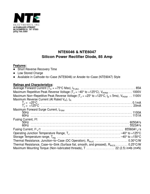
NTE6046 & NTE6047 Silicon Power Rectifier Diode, 85 Amp
Features: D Short Reverse Recovery Time D Low Stored Charge D Available in Cathode–to–Case (NTE6046) or Anode–to–Case (NTE6047) Style Ratings and Characteristics: Average Forward Current (TC = +75°C Max), IF(AV) . . . . . . . . . . . . . . . . . . . . . . . . . . . . . . . . . . . . . 85A Maximum Repetitive Peak Reverse Voltage (TJ = –40° to +125°C), VRRM . . . . . . . . . . . . . . . . 1000V Maximum Non–Repetitive Peak Reverse Voltage (TJ = +25° to +125°C, tp ≤ 5ms), VRSM . . 1100V Maximum Reverse Current (At Rated VR), IR TJ = +25°C . . . . . . . . . . . . . . . . . . . . . . . . . . . . . . . . . . . . . . . . . . . . . . . . . . . . . . . . . . . . . . . . 0.1mA TJ = +125°C . . . . . . . . . . . . . . . . . . . . . . . . . . . . . . . . . . . . . . . . . . . . . . . . . . . . . . . . . . . . . . 20mA Maximum Forward Surge Current, IFSM 50Hz . . . . . . . . . . . . . . . . . . . . . . . . . . . . . . . . . . . . . . . . . . . . . . . . . . . . . . . . . . . . . . . . . . . . . 1100A 60Hz . . . . . . . . . . . . . . . . . . . . . . . . . . . . . . . . . . . . . . . . . . . . . . . . . . . . . . . . . . . . . . . . . . . . . 1151A Fusing Current, I2t 50Hz . . . . . . . . . . . . . . . . . . . . . . . . . . . . . . . . . . . . . . . . . . . . . . . . . . . . . . . . . . . . . . . . . . . 6050A2s 60Hz . . . . . . . . . . . . . . . . . . . . . . . . . . . . . . . . . . . . . . . . . . . . . . . . . . . . . . . . . . . . . . . . . . . 5523A2s Fusing Current, I2pt . . . . . . . . . . . . . . . . . . . . . . . . . . . . . . . . . . . . . . . . . . . . . . . . . . . . . . . 85560A2ps Operating Junction Temperature Range, TJ . . . . . . . . . . . . . . . . . . . . . . . . . . . . . . . . . . –40° to +125°C Storage Temperature range, Tstg . . . . . . . . . . . . . . . . . . . . . . . . . . . . . . . . . . . . . . . . . . . –40° to +150°C Thermal Resistance, Junction–to–Case (DC Operation), RthJC . . . . . . . . . . . . . . . . . . . . . . 0.30°C/W Thermal Resistance, Case–to–Sink (Surface flat, smooth, and greased), RthCS . . . . . . . . 0.25°C/W Maximum Mounting Torque (Non–lubricated threads), T . . . . . . . . . . . . . . . . . . . 22 (2.5) in•lb (m•N)
XMT604智能控制仪
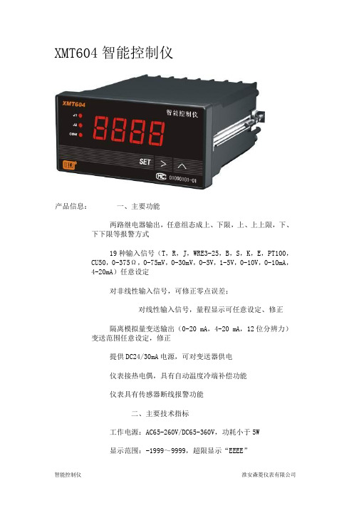
XMT604智能控制仪
产品信息: 一、主要功能
两路继电器输出,任意组态成上、下限,上、上上限,下、下下限等报警方式
19种输入信号(T,R,J,WRE3-25,B,S,K,E,PT100,CU50,0-375Ω,0-75mV,0-30mV,0-5V,1-5V,0-10V,0-10mA,
4-20mA)任意设定
对非线性输入信号,可修正零点误差;
对线性输入信号,量程显示可任意设定、修正
隔离模拟量变送输出(0-20 mA,4-20 mA,12位分辨力)变送范围任意设定,修正
提供DC24/30mA电源,可对变送器供电
仪表接热电偶,具有自动温度冷端补偿功能
仪表具有传感器断线报警功能
二、主要技术指标
工作电源:AC65-260V/DC65-360V,功耗小于5W
显示范围:-1999~9999,超限显示“EEEE”
测量精度:0.2%FS
继电器触点容量:AC250V/3A(阻性负载)
继电器触点寿命:105 次
环境温度:0~50℃,湿度≤85%RH,无腐蚀气体场合 数码显示尺寸:0.56英寸
外型尺寸:96×48×112(mm)(横)
开孔尺寸:92×44(mm)
XMT604B带4-20mA变送输出-。
霍尔元件技术指标参考

霍尔元件技术指标1相关参数1.1封装形式 TO-92(三脚插片),SOT-23(三脚贴片)。
还有SIP-4(四脚插片),SOT-143(四脚贴片)和SOT-89(四脚贴片) 1.2电源 有3.5~24V ,2.5~3.5V ,2.5~5V1.3灵敏度Kh 数量级在C m /1033,且数值越大灵敏度越高1.4霍尔电势温度αα越小,设备精确度越大(必要时可以增加温度补偿电路)1.5额定控制电流cI 一般在几mA~几十mA ,尺寸越大其值越大(尺寸大的可达几百mA )1.6型号 开关型的、线性的、单极性的、双极性的。
双极开关霍尔元件:177A 、177B 、177C 单极霍尔开关元件:AH175、732、1881、S41、SH12AF 、3144、44E 、3021、137、AH137、AH284线性霍尔元件:3503、S496B 、49E 锁定霍尔元件:ATS175、AH173、SS413A 、3172、3075互补双输出开关霍尔元件:276A 、276B 、276C 、277A 、277B 、277C 信号霍尔元件:211A 、211B 、211C 微功耗霍尔元件:TEL4913、TP4913、A3212、A3211。
(具体霍尔开关元件见附录)1.7输入电阻和输出电阻 一般在几Ω到几百Ω,且输入电阻要大于输出电阻1.8外接上拉电阻 一般大于1K Ω。
对一般TTL 电路,由于其高电平电压较低,用于驱动CMOS 电路时,增加上拉电阻,可以提高其高电平的电压。
常用的阻值是4.7k 或10k 。
上拉电阻的是接在1脚电源Vcc 和3脚信号输出Vout 之间。
1.9功能分类 按照霍尔器件的功能可将它们分为: 霍尔线性器件 和 霍尔开关器件 。
前者输出模拟量,后者输出数字量。
都是输出高电平脉冲信号,不同的是开关型相当于到GS 设定值时电平反转;线性的可能是电压逐渐变化,到一定时使后处理电路输出反电平。
一般建议用线性的,开关型常因为温度等原因使得设定值漂移,导致灵敏度下降。
