2-826936-0中文资料
5829中文资料

T E Logic Supply Voltage, VDD .................. 7.0 V N F Input Voltage Range, O E VIN ....................... -0.3 V to VDD + 0.3 V
12.5
= 6°C/W R θJT
10
7.5
5.0
2.5
0 25
R θJA = 30°C/W
50
75
100
TEMPERATURE IN °C
125
150
Dwg. GP-020B
115 Northeast Cutoff, Box 15036 Worcester, Massachusetts 01615-0036 (508) 853-5000 Copyright © 1991, 1995 Allegro MicroSystems, Inc.
Storage Temperature Range,
F TS ............................... -55°C to +150°C
* Fault conditions that produce excessive junction
— temperature will activate device thermal shut-
FEATURES
s 1.6 A Continuous Output Current s 50 V Minimum Sustaining Voltage s Internal Current Sensing s Constant-Frequency PWM Current Control s Control for External High-Side Driver s To 3.3 MHz Data Input Rate s Low-Power CMOS Logic & Latches s Internal Pull-Ups for TTL Compatibility s User-Defined Output Enable Timeout s Internal Thermal Shutdown Circuitry
3590S-2-102L - 数据表说明书

o nl i ne*RoHS Directive 2002/95/EC Jan. 27, 2003 including annexand RoHS Recast 2011/65/EU June 8, 2011. Specifi cations are subject to change without notice.Customers should verify actual device performance in their specifi c applications.Stop Strength..............................................................................................................................................................................45 N-cm (64 oz.-in.) minimum Mechanical Angle ...........................................................................................................................................................................................3600 ° +10 °, -0 °Torque (Starting & Running) ................................................................................................................................0.35 N-cm (0.5 oz.-in.) maximum (unsealed) 1.1 N-cm (1.5 oz.-in.) maximum (sealed) Mounting ..............................................................................................................................................................................55-80 N-cm (5-7 lb.-in.) (plastic) 90-113 N-cm (8-10 in.-lb.) (metal)Shaft Runout......................................................................................................................................................................................0.13 mm (0.005 in.) teral Runout ...................................................................................................................................................................................0.20 mm (0.008 in.) T.I.R.Shaft End Play ...................................................................................................................................................................................0.25 mm (0.010 in.) T.I.R.Shaft Radial Play ...............................................................................................................................................................................0.13 mm (0.005 in.) T.I.R.Pilot Diameter Runout .......................................................................................................................................................................0.08 mm (0.003 in.) T.I.R.Backlash ............................................................................................................................................................................................................1.0 ° maximum Weight ........................................................................................................................................................................................................Approximately 19 G Terminals ................................................................................................................................................................................................Solder lugs or PC pins Soldering ConditionManual Soldering...........................................................96.5Sn/3.0Ag/0.5Cu solid wire or no-clean rosin cored wire; 370 °C (700 °F) max. for 3 seconds Wave Soldering ...................................................................................96.5Sn/3.0Ag/0.5Cu solder with no-clean fl ux; 260 °C (500 °F) max. for 5 seconds Wash processes .......................................................................................................................................................................................Not recommended Marking .....................................Manufacturer’s name and part number, resistance value and tolerance, linearity tolerance, wiring diagram, and date code.Ganging (Multiple Section Potentiometers) ......................................................................................................................................................1 cup maximum Hardware ............................................................................................................One lockwasher and one mounting nut is shipped with each potentiometer.NOTE: For Anti-rotation pin add 91 after confi guration dash number. Example: -2 becomes -291 to add AR pin.1At room ambient: +25 °C nominal and 50 % relative humidity nominal, except as noted. 2Consult manufacturer for complete specifi cation details for resistances below 1k ohms.BOLDFACE LISTINGS ARE IN STOCK AND READILY AVAILABLETHROUGH DISTRIBUTION. FOR OTHER OPTIONS CONSULT FACTORY.ROHS IDENTIFIER: L = COMPLIANTBLANK = NON-COMPLIANT**** NON-COMPLIANT VERSIONS ARE AVAILABLE BUT NOT RECOMMENDED FOR NEW DESIGNS.Recommended Part Numbers(Printed Circuit)(Solder Lug)(Solder Lug)Resistance (Ω)Resolution (%)3590P-2-102L 3590S-2-102L 3590S-1-102L 1,000.0293590P-2-202L 3590S-2-202L 3590S-1-202L 2,000.0233590P-2-502L 3590S-2-502L 3590S-1-502L 5,000.0253590P-2-103L 3590S-2-103L 3590S-1-103L 10,000.0203590P-2-203L 3590S-2-203L 3590S-1-203L 20,000.0193590P-2-503L 3590S-2-503L 3590S-1-503L 50,000.0133590P-2-104L3590S-2-104L3590S-1-104L100,000.009*R o H S C O M P L I A N T V E R S I O N S A V A I L A B L EonnecPanel Thickness Dimensions(For Bushing Mount Only)1.60 +.08/-.03(.063 +.003/-.001)DIA.ANTI-ROTATION PINAnti-rotation pin hole is shown at six o'clock position for reference only. The actual location is determined by the customer's application. Refer to the front view of the potentiometer to see the location of the optional A/R pin.Panel thickness and hole diameters arerecommended for best fit. However, customers may adjust the dimensions to suit their specific application.Product DimensionsSpecifi cations are subject to change without notice.Customers should verify actual device performance in their specifi c applications.REV. 11/11MOUNTING SURFACE-2, -4, -6, -8 Confi gurations-1, -3, -5, -7 Confi gurationsRecommended PCB LayoutHOLE DIAMETER5.08(.200) 5.08(.200)6.99(.275)SchematicTOLERANCES: EXCEPT WHERE NOTED .508 .127DECIMALS: .XX ± (.02), .XXX ±(.005)FRACTIONS: ±1/64 MM DIMENSIONS:(IN.)Shaft & Bushing Confi gurations(Bushing - DxL, Shaft - D):(-1) Plastic Bushing (3/8 ” x 5/16 ”) and Shaft (.2480 + .001, - .002)(-2) Metal Bushing (3/8 ” x 5/16 ”) and Shaft (.2497 + .0000, - .0009)(-3) Sealed, Plastic Bushing (3/8 ” x 5/16 ”) and Shaft (.2480 + .001, - .002)(-4) Sealed, Metal Bushing (3/8 ” x 5/16 ”) and Shaft (.2497 + .0000, - .0009)(-5) Metric, Plastic Bushing (9 mm x 7.94 mm) and Shaft (6 mm + 0, - .076 mm)(-6) Metric, Metal Bushing (9 mm x 7.94 mm) and Shaft (6 mm + 0, - .023 mm)(-7) Metric, Sealed, Plastic Bushing (9 mm x 7.94 mm) and Shaft (6 mm + 0, - .076 mm)(-8) Metric, Sealed, Metal Bushing (9 mm x 7.94 mm) and Shaft (6 mm + 0, - .023 mm)Terminal Styles“P” Terminal Style“S” Terminal Style。
GigaSPEED XL 3071E-B ETL Verified Category 6 U UTP
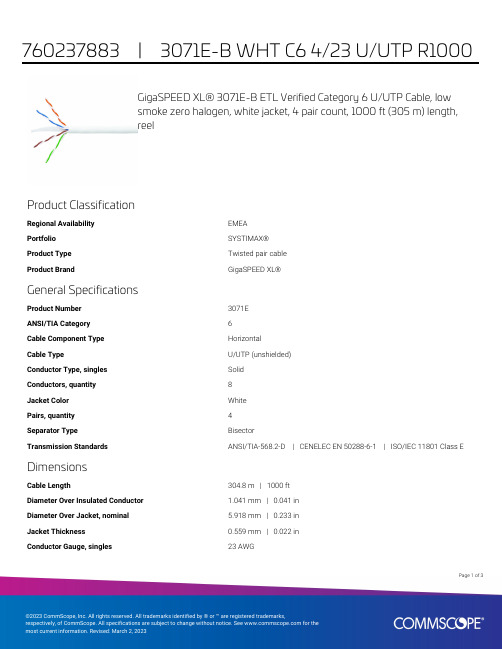
GigaSPEED XL® 3071E-B ETL Verified Category 6 U/UTP Cable, lowsmoke zero halogen, white jacket, 4 pair count, 1000 ft (305 m) length,reelProduct ClassificationRegional Availability EMEAPortfolio SYSTIMAX®Product Type Twisted pair cableProduct Brand GigaSPEED XL®General SpecificationsProduct Number3071EANSI/TIA Category6Cable Component Type HorizontalCable Type U/UTP (unshielded)Conductor Type, singles SolidConductors, quantity8Jacket Color WhitePairs, quantity4Separator Type BisectorTransmission Standards ANSI/TIA-568.2-D | CENELEC EN 50288-6-1 | ISO/IEC 11801 Class E DimensionsCable Length304.8 m | 1000 ftDiameter Over Insulated Conductor 1.041 mm | 0.041 inDiameter Over Jacket, nominal 5.918 mm | 0.233 inJacket Thickness0.559 mm | 0.022 inConductor Gauge, singles23 AWG13Page ofCross Section DrawingElectrical Specificationsdc Resistance Unbalance, maximum 5 %dc Resistance, maximum7.61 ohms/100 m | 2.32 ohms/100 ftDielectric Strength, minimum2500 VdcMutual Capacitance at Frequency 5.6 nF/100 m @ 1 kHzNominal Velocity of Propagation (NVP)70 %Operating Frequency, maximum300 MHzOperating Voltage, maximum80 VRemote Powering Fully complies with the recommendations set forth by IEEE 802.3bt (Type4) for the safe delivery of power over LAN cable when installed accordingto ISO/IEC 14763-2, CENELEC EN 50174-1, CENELEC EN 50174-2 or TIATSB-184-ASegregation Class cMaterial SpecificationsConductor Material Bare copperInsulation Material PolyolefinJacket Material Low Smoke Zero Halogen (LSZH)Separator Material PolyolefinPage of23Mechanical SpecificationsPulling Tension, maximum11.34 kg | 25 lbEnvironmental SpecificationsInstallation temperature0 °C to +60 °C (+32 °F to +140 °F)Operating Temperature-20 °C to +60 °C (-4 °F to +140 °F)Acid Gas Test Method EN 50267-2-3EN50575 CPR Cable EuroClass Fire Performance B2caEN50575 CPR Cable EuroClass Smoke Rating s1aEN50575 CPR Cable EuroClass Droplets Rating d0EN50575 CPR Cable EuroClass Acidity Rating a1Environmental Space Low Smoke Zero Halogen (LSZH)Smoke Test Method IEC 61034-2Packaging and WeightsCable weight38.097 kg/km | 25.6 lb/kftPackaging Type ReelRegulatory Compliance/CertificationsAgency ClassificationCENELEC EN 50575 compliant, Declaration of Performance (DoP) availableCHINA-ROHS Below maximum concentration valueISO 9001:2015Designed, manufactured and/or distributed under this quality management system REACH-SVHC Compliant as per SVHC revision on /ProductCompliance ROHSCompliantPage of33。
2SK2973中文资料
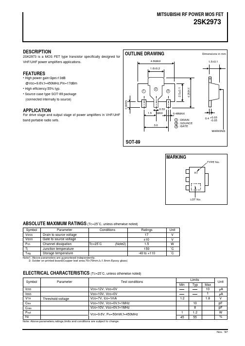
PO, add, t VS. VDD
95 90 PO 85 80 75 70 65 60 ηadd 55 50 45 40 6 7 8 9 35 10 11 12 13
ηt
0
2
INPUT POWER Pin (dBm)
DRAIN SUPPLY VOLTAGE VDD(V)
EQUIVALENT CIRCUIT
OUTLINE DRAWING
4.6MAX 1.6±0.2
Dimensions in mm 1.5±0.1
FEATURES
• High power gain:Gpe≥13dB @VDD=9.6V,f=450MHz,Pin=17dBm • High efficiency:55% typ. • Source case type SOT-89 package (connected internally to source)
S11 -28.167 -52.309 -71.057 -85.910 -97.535 -106.770 -114.312 -120.895 -126.479 -131.266 -136.032 -140.107 -144.290 -148.279 -151.821 -155.417 -159.212 -162.934 -166.562 -170.178 -173.594 -177.132 179.157 175.539 172.187 169.041 165.082 162.211 158.932 155.796 0.014 0.023 0.028 0.030 0.030 0.030 0.028 0.031 0.032 0.037 0.043 0.050 0.059 0.069 0.079 0.091 0.102 0.116 0.128 0.142 0.155 0.168 0.182 0.195 0.208 0.221 0.233 0.243 0.255 0.264
磷酸二氢钾安全技术说明书
化学品未经处理不允许向环境排放。
清洁/吸收措施:
采用安全的方法将泄漏物收集回收或运至废物处理场所处理,采用液体吸收残留物,根据化学品性质进一步处置。清理污染区,洗液排入废水处理池。
第七部分操作处置与储存
操作注意事项:
1、储存防溶液
2、在通风良好的地方才能打开,
3、不要直接于身体接触,
4、使用不发生火花及接地良好的通风系统和电器设备避免成为着火源,
合理小心处理产品不会产生生态问题。
第十三部分废弃处置
废弃物性质:危险废物工业固体废物
废弃方法:对化学品残存物的处置没有统一的国家法规。化学残存物一般作特殊废物。处置前应参阅国家和地方有关法规。我们建议您联系相关机构或认可的废物处置公司,他们会建议您如何处置特殊废物。
包装:处置前应参阅国家和地方有关法规。用外理污染物一样的方法来处理污染的包装。如果没有特别规定,末污染的包装可作家庭废物对待或再循环使用。
4、小心勿使液体沾染未污染的眼睛,
5、若冲洗后仍有刺激感,再反复冲洗,
6、以纱布覆盖双眼,立即就医检查治疗。
吸入:1、救护前做好自己的防护措施,以确保自己的安全,
2、走污染源或将患者移到空气新鲜处,
3、松脱束缚衣物及保持呼吸道畅通,
4、若呼吸困难,供给氧气,
5、若呼吸停止由受过急救训练的人员施以人工呼吸,
Material Safety Data Sheet /物质安全资料表
第一部分化学品及企业标识
化学品中文名称:磷酸二氢钾
化学品俗名或商品名:
化学品英文phate
企业名称、代理商::广东光华化学厂有限公司
地址:广东汕头市光华北四路26号
邮编::515021
VOCO Clip F 型号产品材料安全数据表说明书

1 Names of Material, Preparation and Companytradename:manufacturer/supplieraddress:information sector:emergency information:Clip FVOCO GmbHAnton-Flettner-Str. 1-3D - 27472 CuxhavenScientific DepartmentScientific DepartmentTel.: +49-4721/71 9 - 0Fax:+49-4721/71 9 - 109Tel.:+49-47 21/71 9 - 0emergency call: +49-47 21/71 9 - 02 Composition/Details on Componentspreparation:;ixture of diff. dimethacrylates, sodium fluoride, silicates, initiatora and additives description: Light-curing temporary filling material with fluoridehazardousingredients:nameUDMA CAS-No.41137-60-4content10-20 %danger symbolXiR-categories36-383P ossibleRisksdesignation of risk:special details of risk (R-categories): detrimental effects/symptoms:Xn, harmful20/21/22Harmful by inhalation, in contact with skin and if swallowed4 First-Aid-Measuresgeneralinformation:after inhalation:after skin contact:after eye contact:after swallowing:information for the attending physician: fresh air, in case of indisposition or nausea contact a doctor rinse thoroughly with plenty of waterrinse thoroughly with water, contact a doctorcontact immediately a physicianmaterial for dental or laboratory use only5 Fire Fighting Measuressuitable fire extinguishing agents: unsuitable fire extinguishing agents: particular hazards:fire fighting protective equipment:foam, carbon dioxide, powder fire extinguishers waternoneno data available6 Measures in Case of Unintended Releasemeasures related to persons: environmental measures: procedures of cleaning/uptake additional information:avoid eye and/or skin contactdo not let the material get in contact with sewerage systems take up mechanically, use common absorbentsnone7. Handling and Storage7.1 handling: only by qualified staff in dental offices or dental laboratories7.2instructions for safe handling:instructions on fire and explosion protectionStorage:demands on storerooms and containersindications and prohibitions of storage together with othermaterials:further details on storage conditions:see instructions for useno special measurements are requiredtightly closed at room temperaturestore in good ventilated roomsand areasdo not store together with foodkeep out of the reach of childrenEC-Safety Data Sheet page 1 of 4 according to: 91/155/EEC date: 07.07.95/01 trade name: Clip F revised on: 04/01/20068 8.1Exposition Restriction and Personal Protective Equipment additional information on the equipment of technical facilities: none8.2 components with limitating values related to place of work:CAS-No. name kind value unit additionalinformation:hazards related to place of work are not known.8.3 personal protective equipment:breathing protectionhand protection:eye protection:body protection:protective and hygiene measures: dental office or laboratory working clothes do not breeth or inhale vapour or dustuse of protective gloves is recommended use of protective glasses is recommendedwashing hands9 Physical and Chemical Properties9.1 appearance:form:colour:odour:pastepastywhite acrylate-like9.2 safety data: tested acc. to:9.3pH upon delivery:pH of 10g/l H2O and 20°C:change of state:boiling point/area:melting point/area:flash point:inflammability:ignition temperature:autoignition:fire advancing properties:explosion hazards:explosion limits: LEL:vapour pressure (°C)density (°C)bulk density:solubility in water (20°C) (°C):in (°C)solubility in fat:distribution coefficient n-octanol/water:viscosity (°C):solvent separation test:solvent content:further particulars:no data availableno data availableno data availableno data available °Cno data available °Cno data available °Cno data availableno data available °Cno data availableno data availableno data availableUEL:no data availableno data availableno data available hPano data availableno data available mg/lno data available mg/lno data availableno data availableno data availableno data available %no data available %none10 Stability and Reactivityconditions to be avoided:materials to be avoided:hazardous products of decomposition: further particulars:Influence of light, heatradical releasing agent, e. g. peroxides HCN, CyanidesnoneEC-Safety Data Sheet page 2 of 4 according to: 91/155/EEC date: 07.07.95/01 trade name: Clip F revised on: 04/01/200611. ToxicologicalData11.1 toxicological Test: no data availableacute toxicity: no data availableLD50/LC50:component kind value species method of determination11.2specific symptoms in animal test:irritant effect/corrosive action:sensitization:effects of repeated exposure or overexposure(subacute or chronic toxicity):carcinogenic and mutagenic effects hazardous to reproduction:other particulars:practical experience:observations relevant to classifications:other observations:no data availableno data availableno data availableno data availableno data availableno data availableno data availableno data availableno data availableno data available11.3 general remarks: during long-standing product application risks have not become known.12 12.1Ecological Datainformation on elimination: no data availableprocedure analytic method degree of elimination classification evaluation: no data availableadditional information: no data available12.2 behaviour in environmental compartments: no data availablemobility and bioaccumulation potential:no data availableadditional information: none12.3 environmental toxic effects: no data availableaquatic toxicity: no data availableorganism test period test method result assessment behaviour in sewage plants: no data availablerespiratory inhibition of local vitalised sludge: no data available12.4 additional information:CSB-value:BSB5-value:AOX-indication: noneno data available mg/g no data available mg/g no data availablecontains the following heavy metals and compounds (corresponding to guideline 76/464/EWG) according to preparation formula:nonegeneral information:none13 DisposalInstructions13.1 product:recommendation: obey local and governmental regulationswaste category waste name accountability13.2 uncleaned packing material:recommendation:cleaning agents: obey local and governmental regulations obey local and governmental regulations common cleansing agents for the laboratoryEC-Sate Data Sheet page 3 of 4 according to: 91/155/EEC date: 07.07.95/01 trade name: Clip F revised on: 04/01/200614 Particulars on Transport 14.1 land carriage:ADR/RID/GGVS/GGVE-class: warning label:designation of goods: remarks: figure/letter:risk no.:material no.:14.2 inland transport by ship:ADN/ADN R-class:designation of goods:remarks:figure/letter: category: 14.3 see transport:IMDG/GGV sea class: EMS:marine pollutant: correct technical name: remarks: UN-N o.:MFAG:PG:14.4 air transport:ICAO/IATA-class:correct technical name:remarks:UN/ID-No.: PG:14.5 further particulars: No hazardous goods within the meaning of transport regulations15 Regulation15.1 marking: acc. to governmental regulations concerning declaration of dangerous chemicals no marking is prescribeddanger symbol and designation: nonecontains:R-categories: noneS-categories: nonespecial marking of particular preparations: none15.2 national regulations: acc. to article 10 of Directive 66/379 EEC and 67/548 EECrestrictions of employment: noneinstructions in case of interference: noneclassification acc. VbF: not applicabletechnical instruction air: not applicablewater pollution class: no data availableother regulations, restrictions and prohibitions: Directive 91/155 EEC; medical product acc. to 93/42 EEC (medical products).16 OtherP articularsAll information above has been given according to our present state of knowledge. It has been compiled to the best of our knowledge. The above -mentioned data do not represent a guarantee on characteristics. They only describe the safety requirements with regard to our products. They do not represent an assurance of productcharacteristics in the meaning of guarantees.EC-Safety Data Sheet page 4 of 4 according to: 91/155/EEC date: 07.07.95/01 trade name:Clip F revised on: 04/01/2006。
2N2906中文资料

MIN. MAX. UNIT
−
−60
V
−
−40
V
−
−60
V
−
−5
V
−
−600 mA
−
−800 mA
−
−200 mA
−
400
mW
−
1.2
W
−65
+150 °C
−
200
°C
−65
+150 °C
VALUE 438 146
UNIT K/W K/W
1997 Jun 02
3
Philips Semiconductors
DC current gain 2N2906A
collector-emitter saturation voltage base-emitter saturation voltage collector capacitance emitter capacitance transition frequency
PNP switching transistors
Product specification
2N2906; 2N2906A
CHARACTERISTICS Tamb = 25 °C unless otherwise specified
SYMBOL
PARAMETER
CONDITIONS
MIN. MAX. UNIT
2N2906 2N2906A emitter-base voltage collector current (DC) peak collector current peak base current total power dissipation
Interflon Grease HTG化学品安全数据表说明书

第1部分 化学品及企业标识1.1产品识标注册名称Interflon Grease HTG1.2物质与混合物相关识别使用以及不建议使用相关识别用途润滑剂1.3安全数据表供货商详细信息Interflon BV Belder 474704 RK Roosendaal 荷兰电话: +31 (0)165 553911电邮:*********************网站: 电邮(主管人员)*********************1.4紧急电话号码+31 (0)165 55 39 11 (Monday to Friday from 8:30am to 17:00pm).第2部分 危险性概述2.1物质或混合物之分类依据 GHS 分类此混合物未符合分类标准.2.2标示组件标示毋须2.3其他危害PBT 与 vPvB 评估此混合物不含任何评估为 PBT 或 vPvB 之物质.高度关注物质 (SVHC)本产品不含有对人类健康或环境危险的物质(SVHC )。
(SVHC <0.1%(w/w )条例(EC )1907号/ 2006(REACH ),57条)。
.内分泌干扰特性Does not contain an endocrine disruptor (EDC) in a concentration of ≥ 0,1%.第3部分 成分/组成信息3.1物质不相关(混合物)3.2混合物产品说明合成油, 增稠剂, 添加剂和MicPol®的混合物有害成分无.依据 化学品安全技术说明书编写指南 依据法规 (EC) No. 1907/2006 (REACH),由2020/878/EU 修改Interflon Grease HTG版本编号:6.4取代版本: 5:发行日期05.07.2023修订: 05.07.2023物质名称识标重量 %依据 GHS 分类注意事项Propylene CarbonateCAS 编号108-32-72,5 – < 5Acute Tox. 4 / H312Eye Irrit. 2 / H319完整危害与欧盟危害说明:参阅第 16 节.第4部分 急救措施4.1急救措施说明一般注意事项受感染人员不可无人看管. 将患者移出危险区域. 保持受感染人员温暖、静止并覆盖. 立刻脱下所有沾染的衣物. 若有任何疑虑或症状持续,寻求医疗协助. 若昏迷将人员置于复苏姿势。
826-22-032-00-001000;中文规格书,Datasheet资料
RoHS Compliance Statement for the restriction of lead, mercury, cadmium and hexavalent chromium PBB, PBDE, including Octa-BDE, Penta-BDE, Deca -BDE, in electronic equipment and use of PFOA and PFOS in metal plating processes. Reference: 1. Directive 2002/95/EC of the European Parliament and of the Council of January 27 2003 on the restriction of the use of certain hazardous substances in electrical and electronic equipment. 2. Directive 2003/11/EC which amends Council Directive 76/769/EC to include pentabromodiphenyl ether and octabromodiphenyl ether. 3. Directive 2005/618/EC Commission decision of 18 August 2005 amending Directive 2002/95/EC. Establishes threshold limits for Lead, Mercury, Cadmium, Hexavalent Chromium, PBB, and PBDE. 4. Judgment of the Court (Grand Chamber) 1 April 2008, Directive 2002/95/EC-Electrical and electronic equipment Decabromodiphenyl ether (Deca-BDE) Actions for annulment of exemption. 5. EU Directive 2006/122/EC of the European Parliament and of the Council of 12 December 2006, amending Council Directive 76/769/EEC on the restriction of Perfluorooctanoic Acid (PFOA) and Perfluorooctane Sulfanates (PFOS) used during metal plating proபைடு நூலகம்esses. In reference to the directives described above, MILL-MAX Mfg.Corp. declares that lead, mercury, cadmium, hexavalent chromium, polybrominated biphenyls, polybrominated diphenyl ethers, including pentabromodiphenyl ether, octabromodiphenyl ether, decabromodiphenyl ether, Perfluorooctanoic Acid, and Perfluorooctane Sulfanates are not intentionally added to the raw material or processes used for our certified RoHS compliant products except where described and allowed under item 6 of the annex; Applications where lead mercury, cadmium, and hexavalent chromium, which are exempted from the requirements of Article 4 (1) of reference 1. No warranty, liability of indemnification is expressed or implied with this information. Compliance Statement for Registration, Evaluation, Authorization and Restriction of Chemicals (REACH) Reference: 1. Regulation EC No 1907/2006 of the European Parliament and of the Council of 18 December 2006, concerning the Registration, Evaluation, Authorization and Restriction of Chemicals (REACH) 2. ECHA, Candidate list of Substances of Very High Concern (SVHC) http://echa.europa.eu/reach_en.asp Mill-Max is aware of the regulation and the SVHC list the EU published (referenced above). Mill-Max does not produce or sell any of the listed substances in their homogeneous form. These substances are not intentionally added during the manufacturing of any Mill-Max products. To our knowledge, our products do not contain the substances described on the ECHA SVHC list. Testing is not performed for materials and substances that were not intentionally added. No warranty, liability of indemnification is expressed or implied with this information. Mill-Max maintains surveillance of the ECHA website to obtain the latest information and periodically reviews the SVHC list for changes and additions.
BL21-CodonPlus-RP Competent Cells, Part Number 230
BL21-CodonPlus-RP Competent Cells, Part Number 230250*************(24小时)化学品安全技术说明书GHS product identifier 应急咨询电话(带值班时间)::供应商/ 制造商:安捷伦科技贸易(上海)有限公司中国(上海)外高桥自由贸易试验区英伦路412号(邮编:200131)电话号码: 800-820-3278传真号码: 0086 (21) 5048 2818BL21-CodonPlus-RP Competent Cells, Part Number 230250化学品的推荐用途和限制用途BL21-CodonPlus-RP competent cells 230250-41pUC 18 DNA Control Plasmid 200231-42XL10-Gold 2-Mercaptoethanol 200314-43部件号:物质用途:分析试剂。
230250-41BL21-CodonPlus-RP competent cells1 ml(毫升) (10 x 100 µl)200231-42pUC 18 DNA ControlPlasmid0.01 ml(毫升) (0.1 ng/µl)200314-43XL10-Gold2-Mercaptoethanol0.05 ml(毫升)部件号(化学品试剂盒):230250安全技术说明书根据 GB/ T 16483-2008 和 GB/ T 17519-2013GHS化学品标识:BL21-CodonPlus-RP 感受态细胞,部件号 230250物质或混合物的分类根据 GB13690-2009 和 GB30000-2013紧急情况概述BL21-CodonPlus-RP competent cells液体。
pUC 18 DNA Control Plasmid 液体。
Pyxis Lab ST-588 PTSA Fluorescent Polymer Dual Inl

ST-588PTSA/Fluorescent Polymer DualInline SensorUser ManualOctober12,2020Rev.2.00Pyxis Lab,Inc.1729Majestic Dr.Suite5Lafayette,CO80026USA©2017Pyxis Lab,Inc.Pyxis Lab Proprietary and ConfidentialTable of Contents1Introduction21.1Main Features (2)2Specifications3 3Unpacking Instrument43.1Standard Accessories (4)3.2Optional Accessories (5)4Installation64.1ST-588Piping (6)4.2ST-588SS Piping (6)4.3Wiring (7)4.4Connecting via Bluetooth (8)4.5Connecting via USB (8)5Setup and Calibration with uPyxis®Mobile App95.1Download uPyxis®Mobile App (9)5.2Connecting to uPyxis®Mobile App (9)5.3Calibration Screen and Reading (10)5.4Diagnosis Screen (11)5.5Device Info Screen (12)6Setup and Calibration with uPyxis®Desktop App126.1Install uPyxis®Desktop App (12)6.2Connecting to uPyxis®Desktop App (13)6.3Information Screen (13)6.4Calibration Screen (14)6.5Diagnosis Screen (14)7Outputs157.14–20mA Output Setup (15)7.2Communication using Modbus RTU (15)8Sensor Maintenance and Precaution158.1Methods to Cleaning the ST-588 (16)8.2Storage (16)9Troubleshooting17 10Contact Us18Warranty InformationConfidentialityThe information contained in this manual may be confidential and proprietary and is the property of Pyxis Lab,rmation disclosed herein shall not be used to manufacture,construct,or otherwise reproduce the goods rmation disclosed herein shall not be disclosed to others or made public in any manner without the express written consent of Pyxis Lab,Inc.Standard Limited WarrantyPyxis Lab warrants its products for defects in materials and workmanship.Pyxis Lab will,at its option,repair or replace instrument components that prove to be defective with new or remanufactured components (i.e.,equivalent to new).The warranty set forth is exclusive and no other warranty,whether written or oral, is expressed or implied.Warranty TermThe Pyxis warranty term is thirteen(13)months ex-works.In no event shall the standard limited warranty coverage extend beyond thirteen(13)months from original shipment date.Warranty ServiceDamaged or dysfunctional instruments may be returned to Pyxis for repair or replacement.In some in-stances,replacement instruments may be available for short duration loan or lease.Pyxis warrants that any labor services provided shall conform to the reasonable standards of technical com-petency and performance effective at the time of delivery.All service interventions are to be reviewed and authorized as correct and complete at the completion of the service by a customer representative,or des-ignate.Pyxis warrants these services for30days after the authorization and will correct any qualifying deficiency in labor provided that the labor service deficiency is exactly related to the originating event.No other remedy,other than the provision of labor services,may be applicable.Repair components(parts and materials),but not consumables,provided during a repair,or purchased individually,are warranted for90days ex-works for materials and workmanship.In no event will the in-corporation of a warranted repair component into an instrument extend the whole instrument’s warranty beyond its original term.Warranty ShippingA Repair Authorization(RA)Number must be obtained from Pyxis Technical Support before any product can be returned to the factory.Pyxis will pay freight charges to ship replacement or repaired products to the customer.The customer shall pay freight charges for returning products to Pyxis.Any product returned to the factory without an RA number will be returned to the customer.To receive an RMA you can generate a request on our website at https:///request-tech-support/.Pyxis Technical SupportContact Pyxis Technical Support at+1(866)203-8397,*********************,or by filling out a request for support at https:///request-tech-support/.1IntroductionThe Pyxis ST-588inline fluorometer probe simultaneously measures the concentration of PTSA and Fluores-cent Polymer in water.It can be simply inserted to the compression fitting port of a custom-made tee.The standard ST-001installation tee provided with each ST-588sensor,has two¾inch female NPT ports and can be placed to an existing¾inch sample water line.Pyxis Lab also offers2”and3”Tee formats for larger flow installations.The4–20mA current output of the ST-588probe can be connected to any controller that accepts an isolated or non-isolated4–20mA input.The ST-588probe is a smart device.In addition to mea-suring PTSA and Fluorescent Polymer,the ST-588probe has extra photo-electric components that monitor the color and turbidity of the sample water.This extra feature allows automatic color and turbidity com-pensation to eliminate interference commonly associated with real-world waters.The Pyxis ST-588probe has a short fluidic channel and can be easily cleaned.The fluidic and optical ar-rangement of the ST-588probe is designed to overcome shortcomings associated with other fluorometers that have a distal sensor surface or a long,narrow fluidic cell.Traditional inline fluorometers are susceptible to color and turbidity interference and fouling and are difficult to properly clean.1.1Main FeaturesThe ST-588measures PTSA and Fluorescent Polymer in a water sample and includes the following features:•Easy calibration with using uPyxis®Mobile or Desktop App.•Automatic compensation for turbidity up to150NTU and color created by up to10ppm iron or equivalent to10ppm humic acid.•Diagnostic information(probe fouling,color or turbidity over range,failure modes)are available in uPyxis®App or via Modbus RTU.•Easy to remove from the system for cleaning and calibration without the need for any tools.2SpecificationsTable1.ST-588Specifications*With Pyxis’s continuous improvement policy,these specifications are subject to change without notice.†The fluorescent polymer concentration scale is based on the polymer containing0.25mole%fluorescent monomer.Typical polymer specifications are attached below but may vary by producer.‡See Figure4for ST-588SS dimensions.3Unpacking InstrumentRemove the instrument and accessories from the shipping container and inspect each item for any damage that may have occurred during shipping.Verify that all accessory items are included.If any item is missing or damaged,please contact Pyxis Lab Customer Service at*********************.3.1Standard Accessories•Tee Assembly3/4”NPT(1x Tee,O-ring,and Nut)P/N:ST-001*NOTE*ST-001is not included for ST-588SS•8-Pin Female Adapter/Flying Leads Cable(1.5ft)•User Manual available online at https:///support/3.2Optional AccessoriesFigure1.4Installation4.1ST-588PipingThe provided ST-001Tee Assembly can be connected to a pipe system through the3/4”female ports,either socket or NPT threaded.To properly install the ST-588probe into the ST-001Tee Assembly,follow the steps below:1.Insert the provided O-ring into the O-ring groove on the tee.2.Insert the ST-588probe into the tee.3.Tighten the tee nut onto the tee to form a water-tight,compression seal.Figure2.Dimension of the ST-588and the ST-001Tee Assembly(mm)4.2ST-588SS PipingThe ST-588SS probe has3/4”female NPT threaded ports on the probe itself and therefore does not require a custom tee assembly.It is recommended that two3/4”NPT to1/4”tubing adapters are used to connect the probe to the sampling system.Sample water entering the probe must be cooled down to below104°F (40°C).The probe can be held by a1.75-inch pipe clamp or mounted to a panel with four1/4-28bolts.See Figure4for ST-588SS dimensions.Figure3.Dimension of the ST-588SS(inch)4.3WiringIf the power ground terminal and the negative4–20mA terminal in the controller are internally connected (non-isolated4–20mA input),it is unnecessary to connect the4–20mA negative wire(gray)to the4–20mA negative terminal in the controller.If a separate DC power supply other than that from the controller is used,make sure that the output from the power supply is rated for22–26VDC@85mA.*NOTE*The negative24V power terminal(power ground)and the negative4–20mA ter-minal on the ST-588probe are internally connected.Follow the wiring table below to connect the ST-588probe to a controller:Table2.*Internally connected to the power ground4.4Connecting via BluetoothA Bluetooth adapter(P/N:MA-WB)can be used to connect a ST-588probe to a smart phone with the uPyxis®Mobile App or a computer with the uPyxis®Desktop App.Figure4.Bluetooth connection to ST-588probe4.5Connecting via USBA USB-RS485adapter(P/N:MA-485)can be used to connect a ST-588probe to a computer with the uPyxis®Desktop App.*NOTE*Using non-Pyxis USB-RS485adapters may result in permanent damage of the ST-588probe communication hardware.B connection to ST-588probe5Setup and Calibration with uPyxis®Mobile App5.1Download uPyxis®Mobile AppDownload uPyxis®Mobile App from Apple App Store or Google Play.Figure6.5.2Connecting to uPyxis®Mobile AppTurn on Bluetooth on your mobile phone(Do not pair the phone Bluetooth to the ST-588probe).Open uPyxis®Mobile App.Once the app is open the app will start to search for the sensor.Once the uPyxis®Mobile App connects to the sensor,press the ST-588probe.Figure7.5.3Calibration Screen and ReadingWhen connected,the uPyxis®Mobile App will default to the Calibration screen.From the Calibration screen,you can perform calibrations by pressing on Zero Calibration,Slope Calibration,and4–20mA Span for either Fluorescent Polymer or PTSA,independently.Follow the screen instructions for each calibration step.Figure8.5.4Diagnosis ScreenFrom the Diagnosis screen,you can check the diagnosis condition.This feature may be used for technical support when communicating with*********************.To preform a probe cleaniness check,first select the Diagnosis Condition which defines the fluid type that the ST-588probe in currently measuring,then press Cleanliness Check.If the probe is clean,a Clean mes-sage will be shown.If the probe is severely fouled,a Dirty message will be shown.In this case,follow the procedure in the Methods to Cleaning the ST-588section of this manual.Figure9.5.5Device Info ScreenFrom the Device Info screen.You can name the Device or Product as well as set the Modbus address.Figure10.6Setup and Calibration with uPyxis®Desktop App6.1Install uPyxis®Desktop AppDownload the latest version of uPyxis®Desktop software package from:https:///upyxis/this setup package will download and install the Framework4.5(if not previously installed on the PC),the USB driver for the USB-Bluetooth adapter(MA-NEB),the USB-RS485adapter(MA-485),and the main uPyxis®Desktop application.Double click the uPyxis.Setup.exe file to install.Figure11.Click Install to start the installation process.Follow the screen instructions to complete the USB driver and uPyxis®installation.6.2Connecting to uPyxis®Desktop AppWhen the uPyxis®Desktop App opens,click on Device,then click either Connect via USB-Bluetooth or Connect via USB-RS485depending on the connection type.Figure12.6.3Information ScreenOnce connected to the device,a picture of the device will appear on the top left corner of the window and the uPyxis®Desktop App will default to the Information screen.On the Information screen you can set the information description for Device Name,Product Name,and Modbus Address,then click Apply Settings to save.Figure13.6.4Calibration ScreenTo calibrate the device,click on Calibration.On the Calibration screen there are six calibration options:•Fluorescent Polymer:Zero Calibration,Slope Calibration,and4-20mA Span•PTSA:Zero Calibration,Slope Calibration,and4-20mA SpanThe screen also displays the reading of the device.The reading refresh rate is every4seconds.Figure14.6.5Diagnosis ScreenAfter the device has been calibrated and installation has been completed,to check diagnosis,click on Di-agnosis.When in the Diagnosis screen you can view the Diagnosis Condition of the device.This feature may be used for technical support when communicating with*********************.To preform a probe Cleaniness Check,first select the Diagnosis Condition which defines the fluid type that the ST-588probe inCheck.If the probe is clean,a Clean message will be shown.message will be shown.In this case,follow the procedure in theof this manual.Figure15.7Outputs7.14–20mA Output SetupThe4–20mA output of the ST-588sensor is scaled as:•Fluorescent Polymer:–4mA=0ppm–20mA=20ppm•PTSA:–4mA=0ppb–20mA=200ppb7.2Communication using Modbus RTUThe ST-588probe is configured as a Modbus slave device.In addition to the ppm Fluorescent Polymer and ppb PTSA values,many operational parameters,including warning and error messages,are available via a Modbus RTU connection.Contact Pyxis Lab Customer Service(*********************)for more informa-tion.8Sensor Maintenance and PrecautionThe ST-588probe is designed to provide reliable and continuous Fluorescent Polymer and PTSA readings even when installed in moderately contaminated industrial cooling waters.Although the optics are com-pensated for the effects of moderate fouling,heavy fouling will prevent the light from reaching the sensor, resulting in low readings and the potential for product overfeed if the ST-588probe is used as part of an au-tomated control system.When used to control product dosing,it is suggested that the automation system be configured to provide backup to limit potential product overfeed,for example by limiting pump size or duration,or by alarming if the pumping rate exceeds a desired maximum limit.The ST-588probe is designed to be easily removed,inspected,and cleaned if required.It is suggested that the ST-588probe be checked for fouling and cleaned/calibrated on a monthly basis.Heavily contam-inated waters may require more frequent cleanings.Cleaner water sources with less contamination may not require cleaning for several months.The need to clean the ST-588probe can be determined by the Cleanliness Check using either the uPyxis®Mobile App(see the Mobile Diagnosis Screen section)or the uPyxis®Desktop App(see the Desktop Diagnosis Screen section).8.1Methods to Cleaning the ST-588Any equipment in contact with industrial cooling systems is subject to many potential foulants and con-taminants.Our inline probe cleaning solutions below have been shown to remove most common foulants and contaminants.A small,soft bristle brush,Q-Tips cotton swab,or soft cloth may be used to safely clean the probe housing and the quartz optical sensor channel.These components and more come with a Pyxis Lab Inline Probe Cleaning Solution Kit(P/N:SER-01)which can be purchased at our online Estore/Catalog https:///product/probe-cleaning-kit/Figure16.Inline Probe Cleaning Solution KitTo clean the ST-588probe,soak the lower half of the probe in100mL inline probe cleaning solution for 10minutes.Rinse the ST-588probe with distilled water and then check for the flashing blue light inside the ST-588probe quartz tube.If the surface is not entirely clean,continue to soak the ST-588probe for an e the small,soft bristle brush and Q-Tips cotton swabs as necessary to remove any remaining contaminants in the ST-588probe quartz tube.8.2StorageAvoid long term storage at temperature over100°F.In an outdoor installation,properly shield the ST-588 probe from direct sunlight and precipitation.9TroubleshootingIf the ST-588probe output signal is not stable and fluctuates significantly,make an additional ground con-nection––connect the clear(shield,earth ground)wire to a conductor that contacts the sample water electrically such as a metal pipe adjacent to the ST-588tee.Carry out routine calibration verification against a qualified Fluorescent Polymer and PTSA combined stan-dard.After properly cleaning the ST-588sensor,carry out the zero point calibration with distilled water and slope calibration using the qualified Fluorescent Polymer and PTSA combined standard.10Contact UsPyxis Lab,Inc1729Majestic Dr.Suite5Lafayette,CO80026USAPhone:+1(866)203-8397Email:*********************。
Skirrow琼脂产品说明书
化学品安全技术说明书第一部分化学品及企业标识产品中文名称:Skirrow琼脂产品英文名称:Skirrow Agar产品编号:027385企业名称:广东环凯微生物科技有限公司地址:广东省广州市黄埔区广州开发区科学城神舟路788号邮编:510663公司网址电子邮件地址:*********************传真号码:************销售热线:************-8602技术热线:************-8877/8876推荐用途和限制用途:生化研究/分析第二部分危险性概述GSH危害性类别非危险物质或混合物GSH标签要素非危险物质或混合物其它危害(健康危害、环境危害)未见报道第三部分成分/组成信息混合物化学品成分:参考培养基使用说明。
有害物质成分:无第四部分急救措施一般信息:无特殊的措施要求。
皮肤接触:立即用清水彻底清洗。
眼睛接触:立即提起眼睑,用大量流动清水冲洗15min。
如不适就医。
吸入:如果吸入,将人员移动到新鲜空气处,如果没有呼吸,进行人工呼吸操作,并联系医生。
食入:如误食,用水冲洗口腔,如不适就医。
就医信息:出示产品使用说明或者此SDS。
第六部分 泄露应急处理个人防护:穿个人实验服,佩戴手套和口罩,避免吸入干粉。
环境保护措施:用湿布和地拖擦拭干净。
清洁/收集措施:保持干燥。
迅速清洗弄脏的区域。
第七部分 操作处置与储存安全操作注意事项:防止粉尘扬起,应提供通风设备。
储存注意事项:贮存于避光、干燥处,用后立即旋紧瓶盖。
第八部分 接触控制/个人防护职业接触限值没有已知的国家规定的暴露极限。
工程控制:提供安全淋浴和洗眼设备个人保护措施呼吸系统防护:在通风橱里称取产品,佩戴口罩。
眼睛防护:佩戴安全眼镜。
身体防护:穿实验室服。
手防护:戴防化学品手套。
其他防护:常规的工业卫生操作,工作后及时清洗双手。
第九部分 理化特性外观:粉末 pH 值: 7.4±0.2 颜色:淡黄色 气味: 特征性 熔点:无数据资料 沸点: 无数据资料 燃点:无数据资料 闪点: 无数据资料 爆炸限度下限:无数据资料 上限: 无数据资料 热分解:无数据资料 溶解性:按产品使用说明上的用量比例加蒸馏水,加热煮沸至完全溶解,溶液呈黄色澄清无沉淀。
ITU-T-G.826
INTERNATIONAL TELECOMMUNICATION UNIONITU-T G.826(12/2002) TELECOMMUNICATIONSTANDARDIZATION SECTOROF ITUSERIES G: TRANSMISSION SYSTEMS AND MEDIA, DIGITAL SYSTEMS AND NETWORKSDigital networks – Quality and availability targetsEnd-to-end error performance parameters and objectives for international, constant bit-rate digital paths and connectionsITU-T Recommendation G.826ITU-T G-SERIES RECOMMENDATIONSTRANSMISSION SYSTEMS AND MEDIA, DIGITAL SYSTEMS AND NETWORKS INTERNATIONAL TELEPHONE CONNECTIONS AND CIRCUITS G.100–G.199G.200–G.299 GENERAL CHARACTERISTICS COMMON TO ALL ANALOGUE CARRIER-TRANSMISSION SYSTEMSG.300–G.399 INDIVIDUAL CHARACTERISTICS OF INTERNATIONAL CARRIER TELEPHONESYSTEMS ON METALLIC LINESG.400–G.449 GENERAL CHARACTERISTICS OF INTERNATIONAL CARRIER TELEPHONESYSTEMS ON RADIO-RELAY OR SATELLITE LINKS AND INTERCONNECTION WITHMETALLIC LINESCOORDINATION OF RADIOTELEPHONY AND LINE TELEPHONY G.450–G.499 TESTING EQUIPMENTS G.500–G.599 TRANSMISSION MEDIA CHARACTERISTICS G.600–G.699 DIGITAL TERMINAL EQUIPMENTS G.700–G.799 DIGITAL NETWORKS G.800–G.899 General aspects G.800–G.809 Design objectives for digital networks G.810–G.819 Quality and availability targets G.820–G.829 Network capabilities and functions G.830–G.839 SDH network characteristics G.840–G.849 Management of transport network G.850–G.859 SDH radio and satellite systems integration G.860–G.869 Optical transport networks G.870–G.879 DIGITAL SECTIONS AND DIGITAL LINE SYSTEM G.900–G.999 QUALITY OF SERVICE AND PERFORMANCE G.1000–G.1999 TRANSMISSION MEDIA CHARACTERISTICS G.6000–G.6999 DIGITAL TERMINAL EQUIPMENTS G.7000–G.7999 DIGITAL NETWORKS G.8000–G.8999For further details, please refer to the list of ITU-T Recommendations.ITU-T Recommendation G.826End-to-end error performance parameters and objectives for international,constant bit-rate digital paths and connectionsSummaryThis Recommendation defines end-to-end error performance parameters and objectives for international digital paths which operate at or above the primary rate and for international digital connections which operate below the primary rate of the digital hierarchy. The objectives given are independent of the physical network supporting the path or connection.For digital paths which operate at or above the primary rate, this Recommendation is based upon a block-based measurement concept using error detection codes inherent to the path under test. This supports in-service measurements.For digital connections which operate below the primary rate of the digital hierarchy, this Recommendation is based upon bit error and bit error ratio measurements. This approach does not support in-service measurements.Annex A deals with the definition of availability of the path or connection. Annexes B, C and D give specific information concerning PDH, SDH and cell-based transmission paths.It is not required to apply this Recommendation to connections which operate below the primary rate using equipment designed prior to the adoption of this Recommendation in December 2002.This Recommendation deals with the performance of PDH paths, and of those SDH paths using equipment designed prior to the adoption of ITU-T Rec. G.828 in March 2000. ITU-T Rec. G.828 deals with the performance of SDH paths using equipment designed as of or after the adoption of ITU-T Rec. G.828 in March 2000. New Recommendation G.8201 deals with performance of ODUk paths of the OTN.SourceITU-T Recommendation G.826 was revised by ITU-T Study Group 13 (2001-2004) and approved under the WTSA Resolution 1 procedure on 14 December 2002.KeywordsBackground block error, background block error ratio, bit error, bit error ratio, block-based concept, digital connection, digital path, error detection codes, error performance objectives, error performance parameters, errored second, in-service measurements, severely errored second.ITU-T Rec. G.826 (12/2002) iFOREWORDThe International Telecommunication Union (ITU) is the United Nations specialized agency in the field of telecommunications. The ITU Telecommunication Standardization Sector (ITU-T) is a permanent organ of ITU. ITU-T is responsible for studying technical, operating and tariff questions and issuing Recommendations on them with a view to standardizing telecommunications on a worldwide basis.The World Telecommunication Standardization Assembly (WTSA), which meets every four years, establishes the topics for study by the ITU-T study groups which, in turn, produce Recommendations on these topics.The approval of ITU-T Recommendations is covered by the procedure laid down in WTSA Resolution 1.In some areas of information technology which fall within ITU-T's purview, the necessary standards are prepared on a collaborative basis with ISO and IEC.NOTEIn this Recommendation, the expression "Administration" is used for conciseness to indicate both a telecommunication administration and a recognized operating agency.INTELLECTUAL PROPERTY RIGHTSITU draws attention to the possibility that the practice or implementation of this Recommendation may involve the use of a claimed Intellectual Property Right. ITU takes no position concerning the evidence, validity or applicability of claimed Intellectual Property Rights, whether asserted by ITU members or others outside of the Recommendation development process.As of the date of approval of this Recommendation, ITU had not received notice of intellectual property, protected by patents, which may be required to implement this Recommendation. However, implementors are cautioned that this may not represent the latest information and are therefore strongly urged to consult the TSB patent database.ITU 2003All rights reserved. No part of this publication may be reproduced, by any means whatsoever, without the prior written permission of ITU.ii ITU-T Rec. G.826 (12/2002)CONTENTSPage1 Scope (1)1.1 Application of this Recommendation (1)1.2 Transport network layers (2)1.2.1 PDH and SDH transport networks (2)connections (2)1.2.2 ATM1.3 Allocation of end-to-end performance (3)2 References (3)3 Abbreviations (4)4 Terms and definitions (6)4.5 Error performance events for paths (6)4.6 Error performance events for connections (7)4.7 Error performance parameters (7)5 The measurement of the block (7)5.1 In-service monitoring of blocks (7)5.2 Out-of-service measurements of blocks (8)assessment (8)6 Performance6.1 Implications for error performance measuring devices (8)6.2 Performance monitoring at the near end and far end of a path (8)7 Error performance objectives (8)objectives (8)7.1 End-to-end7.2 Apportionment of end-to-end objectives (10)7.2.1 Allocation to the national portion of the end-to-end path or connection (10)7.2.2 Allocation to the international portion of the end-to-end path orconnection (11)Annex A – Criteria for entry and exit for the unavailable state (11)A.1 Criteria for a single direction (11)A.2 Criterion for a bidirectional path or connection (12)A.3 Criterion for a unidirectional path or connection (12)A.4 Consequences on error performance measurements (12)Annex B – Relationship between PDH path performance monitoring and the block-based parameters (13)B.1 General (13)B.1.1 Block size for monitoring PDH paths (13)B.1.2 Anomalies (13)B.1.3 Defects (13)ITU-T Rec. G.826 (12/2002) iiiPageB.2 Types of paths (14)B.3 Estimation of the performance parameters (14)B.4 In-service monitoring capabilities and criteria for declaration of theperformance parameters (15)B.5 Estimation of performance events at the far end of a path (16)B.6 Differences between this Recommendation and ITU-T Rec. M.2100concerning path performance (16)B.6.1 General (16)B.6.2 Allocationmethodology (16)Annex C – Relationship between SDH path performance monitoring and the block-based parameters (17)C.1 General (17)C.1.1 Converting BIP measurements into errored blocks (17)C.1.2 Block size for monitoring SDH paths (17)C.1.3 Anomalies (17)C.1.4 Defects (17)C.1.5 Measurement of performance events using aggregate parity error counts (18)C.2 Estimation of the performance parameters (19)C.3 Estimation of performance events at the far end of a path (19)Annex D – Relationship between cell-based network performance monitoring and theblock-based parameters (19)D.1 General (19)D.1.1 Block size for monitoring cell-based paths (19)D.1.2 Anomalies (20)D.1.3 Defects (20)D.2 Types of paths (21)D.3 Estimation of the performance parameters (21)D.4 Estimation of performance events at the far end of the path (21)Appendix I – Flow chart illustrating for digital paths the recognition of anomalies,defects, errored blocks, ES and SES (22)Appendix II – Bit errors and block errors, merits and limitations (23)Appendix III – Applicability of this Recommendation to non-public networks (24)iv ITU-T Rec. G.826 (12/2002)ITU-T Recommendation G.826End-to-end error performance parameters and objectives for international,constant bit-rate digital paths and connections1 ScopeThis Recommendation specifies end-to-end error performance events, parameters and objectives for:1) digital paths operating at bit rates at or above the primary rate; and2) N × 64 kbit/s circuit-switched digital connection (1 ≤ N ≤ 24 or 31 respectively).This Recommendation also specifies allocations of the end-to-end performance objectives.1.1 Application of this RecommendationThis Recommendation is applicable to international, constant bit-rate digital paths which operate at or above the primary rate and to international N × 64 kbit/s (1 ≤ N ≤ 24 or 31 respectively) digital connections.NOTE – It is not required to apply this Recommendation to connections which operate below the primary rate using equipment designed prior to the adoption of this Recommendation in December 2002. Performance events and objectives for connections using equipment designed prior to this date are given in ITU-T Rec. G.821 [14].The constant bit-rate digital paths may be based on a Plesiochronous Digital Hierarchy, Synchronous Digital Hierarchy or some other transport network such as cell-based. This Recommendation is generic in that it defines the parameters and objectives for the paths and connections independent of the physical transport network. Compliance with the path performance specification of this Recommendation will, in most cases, also ensure that a client 64 kbit/s connection will meet its requirements. Therefore, this Recommendation and ITU-T Rec. G.828 [24] are currently the only Recommendations required for designing the error performance of digital paths at or above the primary rate1. In accordance with the definition of a digital path, path end points may be located at user's premises.Paths are used to support services such as circuit switched, packet switched and leased circuit services. The quality of such services, as well as the performance of the network elements belonging to the service layer, is outside of the scope of this Recommendation.The performance objectives are applicable to a single direction of the path or connection. The values apply end-to-end over a 27 500 km Hypothetical Reference Path or Connection (see Figure 3), which may include optical fibre, digital radio relay, metallic cable and satellite transmission systems. The performance of multiplex and cross-connect functions employing ATM techniques is not included in these values.The parameter definitions for digital paths which operate at or above the primary rate are block-based, making in-service measurement convenient. In some cases, the network fabric is not able to provide the basic events necessary to directly obtain the performance parameters. In these cases, compliance with this Recommendation can be assessed using out-of-service measurements or estimated by measures compatible with this Recommendation, such as those specified in ____________________1This Recommendation deals with the performance of PDH paths, and of those SDH paths using equipment designed prior to the adoption of ITU-T Rec. G.828 in March 2000. ITU-T Rec. G.828 deals with the performance of SDH paths using equipment designed as of or after the adoption of ITU-T Rec.G.828 in March 2000. New ITU-T Rec. G.8201 deals with the performance of ODUk paths of the OTN.ITU-T Rec. G.826 (12/2002) 12 ITU-T Rec. G.826 (12/2002)Annexes B, C and D. The parameter definitions for digital connections which operate below the primary rate of the digital hierarchy are not block-based; rather, they are based upon bit error and bit-error ratio measurements. 1.2Transport network layersFor paths, this Recommendation specifies the error performance in a given transport network layer. Two cases have to be considered: 1.2.1PDH and SDH transport networksFigure 1 gives the intended scope where ATM does not form part of the end-to-end path. It should be noted that end-to-end performance monitoring is only possible if the monitored blocks together with the accompanying overhead are transmitted transparently to the path end points.G.826_F01Application of this RecommendationNetwork fabric, e.g., PDH, SDH A BNOTE – A and B are path end points located at physical interfaces, e.g. in accordance with ITU-T Rec. G.703 [1].Figure 1/G.826 – Application of this Recommendationfor a non-ATM end-to-end transmission path1.2.2 ATM connectionsWhere the path forms the physical part of an ATM connection (see Figure 2), the overall end-to-end performance of the ATM connection is defined by ITU-T Rec. I.356 [16]. In this case, this Recommendation can be applied with an appropriate allocation to the performance between the path end points where the physical layer of the ATM protocol reference model (see ITU-T Rec. I.321 [15]) is terminated by ATM cross-connects or switches. ATM transmission paths in the physical layer correspond to a stream of cells mapped either into a cell-based format or into SDH or PDH-based frame structures.G.826_F02Under study ITU-T Rec. I.356AAL ATM PLATM PLPLAAL ATM PLG.826 allocatedG.826 allocatedAAL ATM Adaptation Layer ATM ATM Layer PL Physical LayerFigure 2/G.826 – Architectural relationship betweenthis Recommendation G.826 and ITU-T Rec. I.356 [16]1.3 Allocation of end-to-end performanceAllocations of end-to-end performance of CBR paths and connections are derived using the rules laid out in 7.2 which are length- and complexity-based. Detailed allocations of G.826 performance to the individual components (lines, sections, multiplexers and cross-connects, etc.) are outside the scope of this Recommendation, but when such allocations are performed, the national and international allocations as given in 7.2 shall be achieved.2 ReferencesThe following ITU-T Recommendations and other references contain provisions which, through reference in this text, constitute provisions of this Recommendation. At the time of publication, the editions indicated were valid. All Recommendations and other references are subject to revision; users of this Recommendation are therefore encouraged to investigate the possibility of applying the most recent edition of the Recommendations and other references listed below. A list of the currently valid ITU-T Recommendations is regularly published. The reference to a document within this Recommendation does not give it, as a stand-alone document, the status of a Recommendation [1] ITU-T Recommendation G.703 (2001), Physical/electrical characteristics of hierarchicaldigital interfaces.[2] ITU-T Recommendation G.704 (1998), Synchronous frame structures used at 1544, 6312,2048, 8448 and 44 736 kbit/s hierarchical levels.[3] ITU-T Recommendation G.707/Y.1322 (2000), Network node interface for thesynchronous digital hierarchy (SDH), plus Corrigendum 1 (2001), Corrigendum 2 (2001),and Amendment 1 (2001).[4] ITU-T Recommendation G.732 (1988), Characteristics of primary PCM multiplexequipment operating at 2048 kbit/s.[5] ITU-T Recommendation G.733 (1988), Characteristics of primary PCM multiplexequipment operating at 1544 kbit/s.[6] ITU-T Recommendation G.734 (1988), Characteristics of synchronous digital multiplexequipment operating at 1544 kbit/s.[7] ITU-T Recommendation G.742 (1988), Second order digital multiplex equipment operatingat 8448 kbit/s and using positive justification.[8] ITU-T Recommendation G.743 (1988), Second order digital multiplex equipment operatingat 6312 kbit/s and using positive justification.[9] ITU-T Recommendation G.751 (1988), Digital multiplex equipments operating at the thirdorder bit rate of 34 368 kbit/s and the fourth order bit rate of 139 264 kbit/s and usingpositive justification.[10] ITU-T Recommendation G.752 (1988), Characteristics of digital multiplex equipmentsbased on a second order bit rate of 6312 kbit/s and using positive justification.[11] ITU-T Recommendation G.755 (1988), Digital multiplex equipment operating at139 264 kbit/s and multiplexing three tributaries at 44 736 kbit/s.[12] ITU-T Recommendation G.775 (1998), Loss of Signal (LOS), Alarm Indication Signal(AIS) and Remote Defect Indication (RDI) defect detection and clearance criteria for PDHsignals.[13] ITU-T Recommendation G.783 (2000), Characteristics of synchronous digital hierarchy(SDH) equipment functional blocks, plus Corrigendum 1 (2001).ITU-T Rec. G.826 (12/2002) 3[14] ITU-T Recommendation G.821 (2002), Error performance of an international digitalconnection operating at a bit rate below the primary rate and forming part of an Integrated Services Digital Network.[15] ITU-T Recommendation I.321 (1991), B-ISDN protocol reference model and itsapplication.[16] ITU-T Recommendation I.356 (2000), B-ISDN ATM layer cell transfer performance.[17] ITU-T Recommendation I.3622, B-ISDN ATM adaptation layer (AAL) functionaldescription.[18] ITU-T Recommendations I.432.x series, B-ISDN user-network interface – Physical layerspecification.[19] ITU-T Recommendation I.610 (1999), B-ISDN operation and maintenance principles andfunctions, plus Corrigendum 1 (2000).[20] ITU-T Recommendation M.60 (1993), Maintenance terminology and definitions.[21] ITU-T Recommendation M.2100 (1995), Performance limits for bringing-into-service andmaintenance of international PDH paths, sections and transmission systems.[22] ITU-T Recommendation M.2101 (2000), Performance limits and objectives for bringing-into-service and maintenance of international SDH paths and multiplex sections.[23] ITU-T Recommendation M.2101.1 (1997), Performance limits for bringing-into-serviceand maintenance of international SDH paths and multiplex sections.[24] ITU-T Recommendation G.828 (2000), Error performance parameters and objectives forinternational, constant bit-rate synchronous digital paths.[25] ITU-T Recommendation I.325 (1993), Reference configurations for ISDN connection types.[26] ITU-T Recommendation I.340 (1988), ISDN connection types.[27] ITU-T Recommendation G.801 (1988), Digital transmission models.3 AbbreviationsThis Recommendation uses the following abbreviations:AAL ATM Adaptation LayerAIS Alarm Indication SignalATM Asynchronous Transfer ModeUnitAU AdministrativeBBE Background Block ErrorBBER Background Block Error RatioBIP Bit Interleaved ParityB-ISDN Broadband Integrated Services Digital NetworkCBR Constant Bit RateCEC Cell Error ControlCRC Cyclic Redundancy Check____________________2Withdrawn in June 1997.4ITU-T Rec. G.826 (12/2002)EB ErroredBlockEDC Error Detection CodeSecondES ErroredESR Errored Second RatioFAS Frame Alignment SignalHEC Header Error CheckHP Higher order PathReferencePathHRP HypotheticalHRX Hypothetical Reference ConnectionGatewayIG InternationalISDN Integrated Services Digital NetworkMonitoringISM In-ServiceLOF Loss of Frame AlignmentLOM Loss of Multiframe AlignmentLOP Loss Of PointerLOS Loss Of SignalLP Lower order PathSectionMS MultiplexN-ISDN Narrow-band Integrated Services Digital Network NTE Network Terminal EquipmentOAM Operation and MaintenanceODUk Optical Channel Data Unit-kOOS Out-of-ServiceOTN Optical Transport NetworkPDH Plesiochronous Digital HierarchyPEP Path End PointLayerPL PhysicalRDI Remote Defect IndicationREI Remote Error IndicationSDH Synchronous Digital HierarchySES Severely Errored SecondSESR Severely Errored Second RatioSTM Synchronous Transport ModuleEquipmentTE TerminalTIM Trace Identifier MismatchPathTP TransmissionUnitTU TributaryUAS Unavailable SecondUNEQ Unequipped (defect)ContainerVC Virtual4 Terms and definitionsThis Recommendation defines the following terms:4.1 hypothetical reference path: A Hypothetical Reference Path (HRP) is defined as the whole means of digital transmission of a digital signal of specified rate including the path overhead (where it exists) between equipment at which the signal originates and terminates. An end-to-end Hypothetical Reference Path spans a distance of 27 500 km.paths: A digital path may be bidirectional or unidirectional and may comprise both 4.2 digitalcustomer-owned portions and network operator-owned portions.4.2.1 PDH digital paths: With regard to PDH digital paths, ITU-T Rec. M.60 [20] applies.4.2.2 SDH digital paths: An SDH digital path is a trail carrying the SDH payload and associated overhead through the layered transport network between the terminating equipment.4.2.3 cell-based digital paths: Under study.connections: The performance objectives for digital connections are stated for each 4.3 digitaldirection of a N × 64 kbit/s circuit-switched connection (1 ≤ N ≤ 24 or ≤ 31 respectively).ITU-T Rec. I.325 [25] gives reference configurations for the ISDN connection types listed in ITU-T Rec. I.340 [26]. In the context of error performance of 64 kbit/s circuit-switched connection types and the allocation of performance to the connection elements, an all-digital hypothetical reference configuration (HRX) is given in Figure 3. It encompasses a total length of 27 500 km and is a derivative of the standard hypothetical reference configuration given in Figure 1/G.801 [27] and of the reference configuration given in Figure 3/I.325.4.4 generic definition of the block: The error performance of digital paths in this Recommendation is based upon the error performance measurement of blocks. This clause offers a generic definition of the term "block" as follows3:A block is a set of consecutive bits associated with the path; each bit belongs to one and only one block. Consecutive bits may not be contiguous in time.Table 1 specifies the recommended range of the number of bits within each block for the various bit rate ranges. Annexes B, C and D contain information on block sizes of existing system designs.4.5 Error performance events for paths44.5.1 errored block (EB): A block in which one or more bits are in error.4.5.2 errored second (ES): A one-second period with one or more errored blocks or at least one defect.4.5.3 severely errored second (SES): A one-second period which contains ≥30% errored blocks or at least one defect. SES is a subset of ES.Consecutive Severely Errored Seconds may be precursors to periods of unavailability, especially when there are no restoration/protection procedures in use. Periods of consecutive Severely Errored ____________________3Appendix II contains information on block error versus bit-error measurements.4See Appendix I, which contains a flow chart illustrating for digital paths the recognition of anomalies, defects, errored blocks, ES and SES.Seconds persisting for T seconds, where 2 ≤ T < 10 (some Network Operators refer to these events as "failures"), can have a severe impact on service, such as the disconnection of switched services. The only way this Recommendation limits the frequency of these events is through the limit for the SESR. (See Notes 1 and 2.)NOTE 1 – The defects and related performance criteria are listed in the relevant Annexes (B, C or D) for the different network fabrics PDH, SDH or cell-based.NOTE 2 – To simplify measurement processes, the defect is used in the definition of SES instead of defining SES directly in terms of severe errors affecting the path. While this approach simplifies the measurement of SES, it should be noted that there may exist error patterns of severe intensity that w ould not trigger a defect as defined in Annexes B, C and D. Thus, these would not be considered as an SES under this definition. If in the future such severe user-affecting events were found, this definition will have to be studied again.4.5.4 background block error (BBE): An errored block not occurring as part of an SES.4.6 Error performance events for connections4.6.1errored second (ES): It is a one-second period in which one or more bits are in error or during which Loss of Signal (LOS) or Alarm Indication Signal (AIS) is detected.4.6.2severely errored second (SES): It is a one-second period which has a bit-error ratio ≥ 1.10–3 or during which Loss of Signal (LOS) or Alarm Indication Signal (AIS) is detected. 4.7 Error performance parametersError performance should only be evaluated whilst the path is in the available state. For a definition of the entry/exit criteria for the unavailable state, see Annex A.4.7.1 errored second ratio (ESR): The ratio of ES to total seconds in available time during a fixed measurement interval. This parameter is applicable to both paths and connections.4.7.2 severely errored second ratio (SESR): The ratio of SES to total seconds in available time during a fixed measurement interval. This parameter is applicable to both paths and connections. 4.7.3 background block error ratio (BBER): The ratio of Background Block Errors (BBE) to total blocks in available time during a fixed measurement interval. The count of total blocks excludes all blocks during SESs. This parameter is applicable only to paths.5 The measurement of the blockClause 5 is applicable only to paths.5.1 In-service monitoring of blocksEach block is monitored by means of an inherent Error Detection Code (EDC), e.g., Bit Interleaved Parity or Cyclic Redundancy Check. The EDC bits are physically separated from the block to which they apply. It is not normally possible to determine whether a block or its controlling EDC bits are in error. If there is a discrepancy between the EDC and its controlled block, it is always assumed that the controlled block is in error.No specific EDC is given in this generic definition but it is recommended that for in-service monitoring purposes, future designs should be equipped with an EDC capability such that the probability to detect an error event is ≥90%, assuming Poisson error distribution. CRC-4 and BIP-8 are examples of EDCs currently used which fulfil this requirement.Estimation of errored blocks on an in-service basis is dependent upon the network fabric employed and the type of EDC available. Annexes B, C and D offer guidance on how in-service estimates of errored blocks can be obtained from the ISM facilities of the PDH, SDH and cell-based network fabrics respectively.。
Celer T2 - HU0040010 HU0040030 产品安全数据表说明书
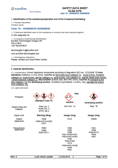
1. Identification of the substance/preparation and of the Company/Undertaking 1.1 Product identifiers Product nameCeler T2 – HU0040010/ HU00400301. 2 Relevant identified uses of the substance or mixture and uses advised against In vitro diagnostic kit.1. 3 Company/Undertaking identification Eurofins Technologies Hungary Kft. Fóti út 56/A.1047 BUDAPEST1. 4 Emergency telephonePlease, contact your local Poison Centre.2. Hazards Identification2.1 Classification : Known hazardous components according to Regulation (EC) No. 1272/2008: T2 toxin standards (methanol, x<10% wt/wt), classified as flammable liquid (category 3), acute toxicity, inhalation (category 4), acute toxicity, dermal (category 4), acute toxicity, oral (category 4), specific target organ toxicity - single exposure (category 2), stop solution (sulfuric acid, 5≤x<15% wt/wt), classified as corrosive to the skin (category 1A) and developing solution (N-Methyl-2-pyrrolidone 1<x>5%), may damage the unborn child (category 1B). 2.2 Label elementsPictogramStandard Toxin T2StopsolutionDeveloping solutionHazard Class andCategoryFlam Liq. 3 Acute Tox. 4 STOT SE 2Skin Corr. 1ARepr. 1BSignal word Warning (Wng) Danger (Dng)Danger (Dng)Hazard statementsH226H302+H312+H332H371 H314H360DPrecautionary statementsP260 P280 P307+P311P260 P264 P280P301+P330+P331 P303+P361+P353P363 P304+P340 P310P305+P351+P338P405 P501P201 P280 P308+P313 P405 P501Hazard statements and precautionary statements full text in section 16.2.3 Supplemental Hazard– none.3. Composition/information on ingredientsComponent Hazardoussubstance% (wt/wt)Componentclassification CAS No. EC No.Microtiter plate - - non pericoloso - -Standard T2 toxinMethanolT2 toxin < 10%< 0,01%Flam. Liq. 2 67-56-1 200-659-6Acute Tox. 3STOT SE 1Acute Tox. 1 21259-20-1 244-297-7 Skin Irrit. 2Enzyme Conjugate Thimerosal < 0,01% non pericoloso 54-64-8 200-210-4 Washing Buffer 10x/20x - - non pericoloso - -Developing solutionN-Methyl-2-pyrrolidone (NMP)1<x<5%Repr. 1BSkin Irrit. 2Eye Irrit. 2STOT SE 3 872-50-4 212-828-1 Stop solution, 8ml/6ml Sulfuric acid 5≤x<15%(1M)Skin Corr.1A 7664-93-9 231-639-5 4. First Aid Measures4.1 Description of first aid measuresIf inhaled: there is a minimal risk of inhalation. In case there appear to be symptoms of exposure, supply fresh air. Monitor respiration. If breathing becomes difficult, consult a doctor and give oxygen. Get medical aid.In case of skin contact: immediately flush with large amounts of water and soap. Remove all contaminated clothing and wash them before reusing. In presence of irritation, get medical aid.In case of eye contact:flush eyes with large amounts of water for at least 15 minutes. Insure adequate washing by keeping eyelids open with fingers. Get medical aid.If swallowed: STOP SOLUTION, DEVELOPING SOLUTION and T2 TOXIN STANDARDS: DO NOT induce vomit. Do not administer anything if victim is unconscious. Rinse mouth with water. Get medical aid.4.2 Most important symptoms and effects, both acute and delayedSee section 2.2 and section 11.DEVELOPING SOLUTION: Larger amounts of vapours may cause fatigue, dizziness, headache, nausea and vomiting. May cause irritation of eyes and skin. Prolonged exposure to vapours may result in damage on liver, kidneys, blood or central nervous system (including brain damage).4.3 Indication of any immediate medical attention and special treatment neededNo data available.5. Firefighting MeasuresT2 toxin standards are flammable. Risks derived from fire are reduced thanks to small volume of material. Other kit components are not flammable.5.1 Extinguishing media: Use water spray, alcohol-resistant foam, dry chemical or carbon dioxide. Keep surrounding materials cool with water spray.5.2 Special hazards arising from the mixture:Stop solution: sulphur oxides. T2 toxin standards: carbon oxides.5.3 Advice for firefighters: in case of fire, if necessary, wear approved self-contained breathing apparatus and5.4 Further information: Keep surrounding materials cool with water spray.6. Accidental Release Measures6.1 Personal precautions, protective equipment and emergency procedures:The small supplied volumes and packaging insure minimal risk of accidental release. In case of spill, wear protective clothing as indicated in section 8. Ensure adequate ventilation.6.2 Environmental precautions: avoid seepage into water course or sewage system.6.3 Methods and materials for containment and cleaning up: Absorb spill with inert absorbent material or absorbent paper. Discard all material into biohazard waste collection container for proper disposal. Wash the contaminated area taking care to avoid seepage into water course or sewage system.6.4 Further information: see section 13 for disposal.7. Handling and Storage7.1 Precautions for safe handlingThere are not special warnings if used according to instruction. Avoid skin and eyes contact. Avoid inhalation of vapour or mist. Wear appropriate personal protective equipment as specified in section 8.7.2 Conditions for safe storage, including any incompatibilitiesKeep products tightly sealed in their original containers. Store bottles between +2°C and +8°C. Avoid physical damage to containers. Do not expose to heat or direct light.The packaging guarantees the component isolation from incompatible material.7.3 Specific end usesIn vitro diagnostic reagents, as described in section 1.2.8. Exposure Controls/Personal Protection8.1 Control parametersComponents with workplace control parameters.Exposure workplace limit values for sulfuric acid (data refer to pure substance): 0,05 mg/m3 (TWA). Exposure workplace limit values for methanol (data refer to pure substance): 200 ppm; 260 mg/m3(TWA). Possible absorption through skin.Exposure workplace limit values for N-methyl-2-pyrrolidone (data refer to pure substance): 10 ppm; 40mg/m3(TWA). Possible absorption through skin8.2 Exposure controls:Adhere to instructions and good laboratory practice. Use disposable latex or nitrile rubber gloves and protective lab coat. The selected protective gloves have to satisfy the specifications of EU Directive 89/686/EEC and the standard EN 374 derived from it. Use equipment for eye protection tested and approved under appropriate government standards such as NIOSH (US) or EN 166(EU). Have emergency shower and eye wash stations available. Always avoid direct contact of the solution with eyes, skin and clothing. Avoid inhalation. Avoid prolonged or repeated exposure.9. Physical and Chemical Properties10. Stability and reactivity10.1 Reactivity: no data available.10.2 Chemical stability: stable under the conditions for storage and handling described in the instructions. Keep in their original containers.10.3 Possibility of hazardous reactions: no data available.10.4 Conditions to avoid: heat, flame, sparks, direct light, incompatible materials.10.5 Incompatible materials: Stop solution: bases, halides, organic materials, carbides, nitrates, picrates, cyanides, chlorates, alkali halides, zinc salts, permanganates, hydrogen peroxide, azides, perchlorates, nitromethane, phosphorous, cyclopentadiene, cyclopentanone oxime, nitroaryl amines, hexalithium disilicide, phosphorous(iii) oxide, powdered metals. T2 toxin standards: acids, oxidizing agents, alkali metals, acid chlorides, acid anhydrides, reducing agents. Developing solution: Strong oxidizing agents.10.6 Hazardous decomposition products: developing solution- thermal decomposition may produce oxides of carbon and nitrogen.11.Toxicological Information11.1 Information on toxicological effectsT2 toxin standards are harmful is inhaled, if swallowed and if absorbed through skin. They may cause skin, eye and respiratory tract irritation. They have specific target organ toxicity - single exposure (category 2). Methyl alcohol may be fatal or cause blindness if swallowed. Effects due to ingestion may include: headache, dizziness, drowsiness, metabolic acidosis, coma, seizures. Symptoms may be delayed. Target organ: liver, kidney.Further information: RTECS: PC1400000 (methanol).Stop solution is classified as corrosive to the skin (category 1A).Causes severe skin burns and eye damage.Toxicological properties have not been further investigated.Further information: RTECS: WS5600000 (sulfuric acid).Developing solution may damage the unborn child (Repr. 1B).It may irritate skin, mucous and eyes. If it inhaled may cause dizziness, headache and nausea.May cause irritation to mucous membranes in mouth , throat and stomach.Prolonged or frequent exposure to vapours of volatile organic compounds may result in damage on liver, kidneys, blood or central nervous system (including brain damage).According to animal tests, N-methyl-2pyrrolidone may cause harm to the unborn childFurther information: RTECS: UY5790000 (N-methyl-2pyrrolidone).Toxicological properties have not been further investigated.12. Ecological InformationThe components are furnished in volumes that do not represent hazard for the environment if used and disposed of correctly.This product contains no components considered to be either persistent, bioaccumulative and toxic (PBT) or very persistent and very bioaccumulative (vPvB).13. Disposal ConsiderationsUse the components according to good laboratory practice. Avoid release to the environment. Do not allow product to reach sewage system. Observe all international and local environmental regulations. Send surplus and non recyclable solutions to a licensed disposal company.14. Transport InformationThough some components are mentioned in legislation on transport of hazardous goods (methanol, UN1230 and sulphuric acid, with not more than 51% pure acid, UN2796), the volumes and the types of containers used with this product are such that this product is exempt from these norms.15. Regulatory InformationThis safety data sheet is in accordance with Regulation (EC) No. 1907/2006 and Regulation No. 453/2010.16. Other informationHazard statements and precautionary statements full textFull text of H-Statements referred to sections 2 and 3Flam Liq. 3 Flammable liquids (category 3)Acute Tox. 4 Acute toxicity (category 4)STOT SE 2 Specific target organ toxicity - single exposure (category 2)Skin Corr. 1A Corrosive to the skin (category 1A)Repr. 1B Toxic for reproduction (category 1B)H226: Flammable liquid and vapourH302+H312+H332: Harmful if swallowed, in contact with skin or if inhaledH314: Causes severe skin burns and eye damageH360D: May damage the unborn childH371: May cause damage to organsPrecautionary statementsP201: Obtain special instructions before useP260: Do not breathe dust/fume/gas/mist/vapours/sprayP264: Wash thoroughly after handlingP280: Wear protective gloves/protective clothing/eye protection/face protectionP301+330+331: if swallowed: Rinse mouth. Do NOT induce vomitingP303+361+353: if on skin (or hair): Take off immediately all contaminated clothing. Rinse skin with water/ showerP304+340: if inhaled: Remove person to fresh air and keep comfortable for breathingP305+P351+P338: If in eyes: rinse cautiously with water for several minutes. Remove contact lenses, if present and easy to do. Continue rinsingP307+P311: IF exposed: Call a POISON CENTER or doctor/ physicianP308+313: If exposed call a doctorP310: Immediately call a POISON CENTER/doctorP363: Wash contaminated clothing before reuseP405: Store locked upP501: Dispose of contents to in accordance with local regulationIMPORTANT! Read the safety data sheets before the use and disposal of this product. Insure that this information is understood by the operators exposed to this product. Use this product for the intended purpose as indicated in the instruction manual.The above information is believed to be accurate and up to date. It is, however, liable to change due to the continuous modification of legislation and of standards and security data. Since the correct or incorrect use of this product is beyond our jurisdiction, this information cannot be expressed or implied to be comprehensive. Eurofins Technologies cannot be held responsible for any improper use of the product, including those uses that could violate current patents or other copyrights. Only the user is responsible for the evaluation of this product’s conformity and of the risks involved before use, and must adopt appropriate precautions towards self and other persons involved.。
Lan-826最详细说明
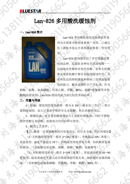
Lan-826多用酸洗缓蚀剂一、Lan-826简介Lan-826多用酸洗缓蚀剂被国家科委列为全国重点科技成果推广项目,已通过化工部技术鉴定并获得国家科委三等发明奖。
Lan-826缓蚀剂首创了多用型酸洗缓蚀剂品种,它能在各种化学清洗用酸——包括氧化性酸和非氧化性酸、多种无机酸和多种有机酸中都具有高效缓蚀作用,并具有优良的抑制渗氢和抑制三价铁加速腐蚀的能力。
酸洗金属时不产生孔蚀。
作为硝酸、盐酸、氨基磺酸、羟基乙酸、草酸、EDTA、硝酸-氢氟酸等多种酸酸洗缓蚀剂,Lan-826缓蚀剂是当前比较优秀的品种。
二、用量与用法1、配液:缓蚀剂的使用浓度一般为0.3%(一吨水加三公斤)。
将计量的缓蚀剂, 加入计量水中搅拌至完全溶解,然后再搅拌均匀。
2、配酸洗液:将计量的酸缓缓加入上述配好的液体,同时不停的搅拌使酸完全溶解,溶液混合均匀后即可使用。
3、酸洗工艺条件:【注:酸量一定要视酸洗的污垢量而定,可以先少量,然后再增加】(1)无机酸使用浓度一般在3-10%(重量),不能超过20%(重量);常温使用,温度不能超过55℃,否则缓蚀剂很容易失效,加快酸对金属的腐蚀。
(无机酸包括盐酸、硝酸、硫酸、磷酸、氢氟酸等)(2)有机酸使用浓度一般在3-20%(重量),常温或加热到60 -90度使用,温度或浓度不要太高否则缓蚀剂可能失效,加快酸对金属的腐蚀。
(有机酸包括氨基磺酸、柠檬酸、草酸、醋酸、EDTA等)。
初次使用或尚没有使用经验的,一定先小量试用满意后再大量使用。
Lan-826缓蚀剂为淡黄色液体,比重1.06(在20℃时),气味(芳香性)小,毒性低(LD50为1130mg/kg),不燃不爆,微碱性。
在常用条件下,其推荐用量和缓蚀性能如表所示。
序号清洗剂名称酸浓度%温度℃LAN-826浓度腐蚀率mm/a缓蚀率%1 加氨柠檬酸3 90 0.05 0.31 99.62 加氨柠檬酸-氟化氢氨1.8-0.24 90 0.05 0.39 99.33 氢氟酸 2 60 0.05 0.69 99.44 盐酸10 50 0.20 0.74 99.45 硝酸10 25 0.25 0.13 99.96 硝酸-氢氟酸(8:2)10 25 0.25 0.24 99.97 氨基磺酸10 60 0.25 0.46 99.78 羟基乙酸10 85 0.25 0.38 99.49 羟基乙酸-甲酸-氟化氢氨2-1-0.25 90 0.25 0.74 99.210 EDTA 10 65 0.25 0.16 99.211 草酸 5 60 0.25 0.40 99.412 磷酸10 85 0.25 0.93 99.913 醋酸10 85 0.25 0.52 98.914 硫酸10 65 0.25 0.67 99.9腐蚀率的计算公式:F=(W1-W2)/ATF-腐蚀速率,g/(m2*h)W1-试验前试片品质,gW2-试验后试片品质,gA-试片面积,m2T-时间,h。
2-硝基间苯二酚-安全技术说明书MSDS

第一部分化学品及企业标识化学品中文名:2-硝基间苯二酚化学品英文名:2-nitroresorcinolCAS No.:601-89-8分子式:C6H5NO4产品推荐及限制用途:工业及科研用途。
第二部分危险性概述紧急情况概述吞咽有害。
皮肤接触有害。
造成皮肤刺激。
造成严重眼刺激。
吸入有害。
可引起呼吸道刺激。
GHS危险性类别根据GB30000-2013化学品分类和标签规范系列标准(参阅第十六部分),该产品分类如下:急性经口毒性,类别4;急性经皮肤毒性,类别4;皮肤腐蚀/刺激,类别2;严重眼损伤/眼刺激,类别2;急性吸入毒性,类别4;特异性靶器官毒性一次接触,类别3。
标签要素:象形图警示词:警告危险性说明:H302 吞咽有害H312 皮肤接触有害H315 造成皮肤刺激H319 造成严重眼刺激H332 吸入有害H335 可引起呼吸道刺激防范说明●预防措施:—— P264 作业后彻底清洗。
—— P270 使用本产品时不要进食、饮水或吸烟。
—— P280 戴防护手套/穿防护服/戴防护眼罩/戴防护面具。
—— P261 避免吸入粉尘/烟/气体/烟雾/蒸气/喷雾。
—— P271 只能在室外或通风良好处使用。
●事故响应:—— P301+P312 如误吞咽:如感觉不适,呼叫解毒中心/医生—— P330 漱口。
—— P302+P352 如皮肤沾染:用水充分清洗。
—— P312 如感觉不适,呼叫解毒中心/医生—— P321 具体治疗(见本标签上的……)。
—— P362+P364 脱掉沾染的衣服,清洗后方可重新使用—— P332+P313 如发生皮肤刺激:求医/就诊。
—— P305+P351+P338 如进入眼睛:用水小心冲洗几分钟。
如戴隐形眼镜并可方便地取出,取出隐形眼镜。
继续冲洗。
—— P337+P313 如仍觉眼刺激:求医/就诊。
—— P304+P340 如误吸入:将人转移到空气新鲜处,保持呼吸舒适体位。
●安全储存:—— P403+P233 存放在通风良好的地方。
- 1、下载文档前请自行甄别文档内容的完整性,平台不提供额外的编辑、内容补充、找答案等附加服务。
- 2、"仅部分预览"的文档,不可在线预览部分如存在完整性等问题,可反馈申请退款(可完整预览的文档不适用该条件!)。
- 3、如文档侵犯您的权益,请联系客服反馈,我们会尽快为您处理(人工客服工作时间:9:00-18:30)。
2-826936-0 Product Details
Home | Customer Support | Suppliers | Site Map | Privacy Policy | Browser Support
© 2008 Tyco Electronics Corporation All Rights Reserved Search
Products Documentation Resources My Account Customer Support Home > Products > By Type > PCB Connectors > Product Feature Selector > Product Details
2-826936-0
Active .100 inch AMPMODU Headers
Always EU RoHS/ELV Compliant (Statement of Compliance)
Product Highlights:
?Header
?Header Type = Breakaway
?Number of Rows = Single
?Number of Positions = 20
?Mating Post Length = 5.80 mm
View all Features | Find Similar
Products
Check Pricing &
Availability
Search for Tooling
Product Feature
Selector
Contact Us About
This Product
Quick Links
Documentation & Additional Information
Product Drawings:
?None Available
Catalog Pages/Data Sheets: ?None Available
Product Specifications:
?None Available
Application Specifications: ?None Available
Instruction Sheets:
?None Available
CAD Files:
?None Available Additional Information:
?Product Line Information
Related Products:
?Tooling
Product Features (Please use the Product Drawing for all design activity)
Product Type Features:
?Product Type = Header
?Number of Positions = 20
?Mount Angle = Vertical
?PCB Retention Feature = No
?Surface Mount Compatible = No
?Board Standoff = Without
?Mounting Ears = Without
?Mating Connector Lock = Without
?Profile = Standard
Mechanical Attachment:
?Mating Post Length (mm [in]) = 5.80 [0.228]
?Panel Attachment = Without
Termination Related Features:
?Termination (Solder) Post Length (mm [in]) =
3.20 [0.126]
?Solder Tail Contact Plating = Tin
Body Related Features:
?Header Type = Breakaway
?Number of Rows = Single
?Centerline, Matrix (mm [in]) = 2.54 [.100]
?Selectively Loaded = No
?Mount Type = PC Board Contact Related Features:
?Contact Mating Area Plating = Tin over Nickel ?Contact Material = Brass
Housing Related Features:
?Housing Material = Thermoplastic Polyester
?Housing Flammability Rating = UL 94V-0
Industry Standards:
?RoHS/ELV Compliance = RoHS compliant, ELV
compliant
?Lead Free Solder Processes = Wave solder
capable to 240°C, Wave solder capable to 260°
C, Wave solder capable to 265°C
?RoHS/ELV Compliance History = Always was
RoHS compliant
Conditions for Usage:
?High Temperature Housing = No
Operation/Application:
?High Speed Serial Data Connector = No Other:
?Brand = AMP
Provide Website Feedback | Contact Customer Support。
