optics_20
NX20 主动式 3D眼镜 说明书
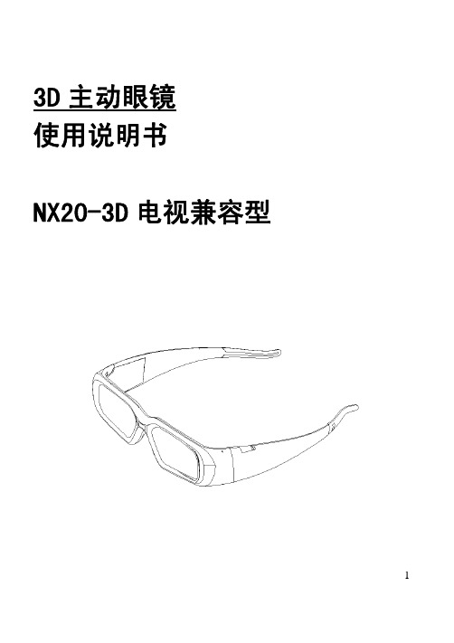
13D 主动眼镜 使用说明书NX20-3D 电视兼容型2产品概述祝贺您购买我司主动式 3D 眼镜,此产品可令您在 3D 电视上获得身临其境的 3D 体验。
我司 NX20 主动式 3D 眼镜必须 3D 电视机结合使用才能享用视觉效果。
支持的 3D 电视TCL L55X11FE3D KDL-60NX810 SHARP52LV925A KDL-55NX810 LED46XT39G3DKDL-60LX900海信LED55XT39G3D KDL-46NX710 46ZF1CKDL-40NX710东芝55ZF1C KDL-55HX800 42LX6500-CASONYKDL-46HX800 47LX6500-CA UA46C7000WF LG55LX6500-CA UA55C7000WF TH-P42GT20CUA55C8000XF TH-P46GT20C UA55C9000ZF TH-P65VT20 LA55C750R2F 松下TH-P50VT20UN55C7000WF UA65C8000XFXXZPS58C7000YF 康佳LED55IS95D三星P63C7000备注:如需查看NX20 立体眼镜支持的 3D 电视的完整列表,请留意我司的最新信息发布。
3零部件与组成部分主动式 3D 眼镜包装箱内装有以下部件及组成。
NX20 主动式 3D 眼镜(1)一根 USB 线缆(1)(1.5m)储物袋和眼镜布(各1)使用手册(1)4NX20 主动式 3D 眼镜备注:可在大多数普通眼镜的基础之上佩戴 NX20 主动式 3D 眼镜 。
开关按钮 按下即可查看电 池剩余电量状态 指示灯立体3D 眼镜完全充电一次大约可以连续畅玩游戏长达35小时。
红灯闪烁表示剩余电量不足需充电USB 接口 为眼镜充电(充电时指示灯为蓝色)红外接受器 请勿阻挡3D 影像观看指南z在荧光灯(50Hz~60Hz)或3波长灯下观看3D影像时,您可能会注意到轻微的画面闪动。
光电子学与光子学讲义-Chapter0-perface讲课教案
1990s: 稀土掺杂光纤(掺铒光纤放大器) 光通信技术的革命
期待新一代光电功能材料的突破 !!!
五.光电子学发展方向与趋势
➢ 量子化(材料的量子结构化)---
采用量子阱、应变量子阱、超晶格、 量子线、量子点等人构改性的材料
➢ 集成化(器件的集成化) ---
一. 光电子学的发展进程
1973年 法国 召开了光子学国际会议 The term “LA PHOTONIQUE” was coined by a French physicist to describe the use of photons in ways analogous to the use of electrons.
❖电
荷
-e
0
❖自
旋
l(h)/2
l(h)
三. 光子学与电子学
光子具有的优异特性: • 光子具有极高的信息容量和效率
• 光子具有极快的响应能力 • 光子系统具有极强的互连能力与并行能力 • 光子具有极大的存储能力
四.光电子学、光子学相关学术领域
• 光电子学物理基础研究
• 激光物理学 • 信息光电子学 • 生物光子学及激光医学 • 微光机电集成系统(MEMS) • 光电子武器 • 微波光子学 • 有机光子学与材料 • 光化学与分子动力学 • 能源 ……
支撑技术:
晶体外延生长工艺 --- MBE, MOCVD, CBE
细微加工工艺 --- 电子束光刻, 反应离子刻蚀(RIE)
聚焦离子束注入与刻蚀,
纳米级图形超微细加工 等
五.光电子学发展方向与趋势
集成化是器件发展水平的标志
集成光发射器:LD+EA Mod.,LD +Driver (HBT)
20倍双组联动变焦距光学系统设计_李宏壮

第35卷第2期2015年2月Vol.35,No.2February,2015光学学报ACTA OPTICA SINICA 20倍双组联动变焦距光学系统设计李宏壮张振铎中国科学院长春光学精密机械与物理研究所,吉林长春130033摘要针对双组联动变焦距系统结构复杂的特点,对其设计过程进行了梳理。
在此基础上编制了可视化辅助设计软件,该软件具有高斯解计算、变倍补偿曲线绘制、像差与外形尺寸分析、相对孔径图输出等功能。
使用该软件可以方便地完成双组联动变焦系统高斯解的合理选择,并给出各组元承担相对孔径及其变化情况,辅助进行初始结构的确定。
利用该辅助设计软件,对一套焦距25~500mm 的20倍可见光波段双组联动连续变焦距系统进行了初始结构设计,并通过整体优化使系统像差得到校正。
设计结果系统光学总长478mm ,各焦距位置在50lp/mm 处轴上视场调制传递函数(MTF)大于0.6,边缘视场MTF 大于0.4,各项指标满足系统要求。
关键词光学设计;双组联动;连续变焦距镜头;高斯光学计算中图分类号TH751文献标识码Adoi :103788/AOS201535.0222003Design of 20×Double-Linkage Continuous Zoom Optical SystemLi Hongzhuang Zhang ZhenduoChangchun Institute of Optics,Fine Mechanics and Physics,Chinese Academy of Sciences,Changchun,Jilin 130033,ChinaAbstract For the complexity of double-linkage zoom system,the design process is settled first,and thevisible assist design software is developed.The function of the software includes Guassian optical calculation,compensation curve drawing,aberration and lens size analysis,relative aperture curve output,ing thesoftware,rational Guassian parameters can be selected conveniently,and the relative aperture and its variationof each group can be given,which can help the designer to select the initial configuration.Then utilizing thesoftware,the initial design can performed for a double-linkage zoom system with focal length range from25mm to 500mm.And through integrated optimization,the system aberration is corrected and balanced.Thedesign results demonstrate that the total optical length is 478mm,and the modulation transfer function (MTF)at 50lp/mm for each zoom configuration is higher than 0.6for center field,and higher than 0.4for edge field.All indexes satisfy the command of system.Key words optical design;double linkage;continuous zoom system;Guassian optical calculationOCIS codes 220.3620;220.4830收稿日期:2014-09-01;收到修改稿日期:2014-10-21作者简介:李宏壮(1980—),男,副研究员,博士,主要从事光学设计、检测、主动光学、大口径望远镜波前探测等方面的研究。
Opticon OPR-3201Z 手持式条码扫描器说明书

Cabled Scanners_OPR-3201Z_07.2023© Copyright Opticon. All rights reserved. This information is subject to change without prior notice. For availability, contact your local representative.MSI/Plessey, UK/Plessey, S-Code, Telepen, Tri-Optic Postal code: Chinese Post, Korean Postal Authority codeDurabilityTemperature in operation: -5 to 50 0C / 23 to 122 0F Temperature in storage: -20 to 60 0C / -4 to 140 0F Humidity in operation: 5% to 95% (non-condensing) Humidity in storage: 5% to 95% (non-condensing)Ambient light immunity: Fluorescent 3,000 lx, direct sun 50,000 lx, incandescent 3,000 lx max Drop test: 1.5 m / 5 ft drop onto concrete surface Vibration test: 10 - 100Hz with 2G for 1 hour Protection rate: IP42PhysicalDimensions Scanner (W x H x D): 56 x 149 x 109 mm / 2.20 x 5.87 x 4.29 inWeight body: Ca. 90 g / 3.2 oz (excl. cable)Dimensions Stand (W x H x D): 146 x 106 x 295 mm / 5.75 x 4.17 x 11.61 in (excl. scanner)Weight Stand: Ca. 390 g / 3.76 ozCase: ABS. Black or White (Antimicrobial optional)Regulatory & safetyProduct compliance: CE, FCC, VCCI, RoHS,JIS-C-6802 Class 2, IEC60825-1 Class 2, FDA CDRH Class II, EN55022, EN55024ItemsEnclosed: StandSold separately: Power supply 6V/2A (for RS232)ModelsInterface versions: USB, RS232is optional Color versions: Black, WhiteOperating indicatorsVisual: 1 large LED (red/green/orange)Non-visual: buzzerOperating keysEntry options: 1 scan keyCommunicationRS232C: DB9 connector with external power supply USB: ver. 1.1, HID/VCP, USB-A connectorPowerVoltage requirement: 5V ±10% (USB), 6V (min 5.5, max. 6.5) (RS232)Current consumption: Max. 200 mABarcode scanner opticsLight source: 650 nm visible laser diode Scan method: Bi-directional scanning Scan rate: Up to 100 scans / secondTrigger mode: Manual, auto-trigger, stand detection Reading pitch angle: ± 350Reading skew angle: -500 to -80, 80 to +500 Reading tilt angle: ± 200Curvature: R ≥15 mm (EAN8), R ≥20 mm (EAN13)Min. resolution at PCS 0.9: 0.127 mm / 5 mil Min. PCS value: 0.45Depth of field at code 39:40 - 400 mm (1.0 mm) / 1.57 - 15.75 in (39 mil)20 - 300 mm (0.5 mm) / 0.79 - 11.81 in (20 mil)20 - 200 mm (0.25 mm) / 0.79 - 7.87 in (10 mil)20 - 100 mm (0.15 mm) / 0.79 - 3.94 in (6 mil)30 - 70 mm (0.127 mm) / 1.18 - 2.76 in (5 mil)Supported symbologiesBarcode (1D): JAN/UPC/EAN incl. add on, Codabar/NW-7, Code 11, Code 39, Code 93, Code 128, GS1-128 (EAN-128), GS1 DataBar (RSS), IATA, Industrial 2 of 5, Interleaved 2 of 5, ISBN-ISSN-ISMN, Matrix 2 of 5,Product SpecificationsOPR-3201Z。
Skylane Optics 光纤收发器产品手册说明书

PUBLIC_REV2017_AProduct GuideTransceivers for Datacom and TelecomApplicationsData CenterOptimized fiber optic solution for Data Center Application FTTHBroad Product Portfoloio and Technology for FTTH Broadband Networks WirelessEnabling Rapid Expnsion of Mobile Broadband Enterprise - CampusWe provides the enterprise network market with the most comprehensive product combinationsSkylane Optics is a leading provider of transceivers for optical communication. We offer an extensive portfolio for the enterprise, access, and metropolitan fiber optical market.The offerings provided by Skylane Optics are characterized by high quality and performance. In combination with our strong technical support, we enable our customers to build cost optimized network solutions solving existing and future capacity needs.SolutionsOur Engineering and Logistics Center> Inventory, logistics, programming and quality control based in Fraire, Belgium> IQC [Incoming Quality Control] and OQC [Outgoing Quality Control]> 100% optimized for handling of transceivers > SD [ANSI/ESD S20.20] compliant > Clean room environment; class 100K > Traceability> High CapacityOur Laboratory> Lab, based in Fraire, Belgium > Technical support > RMA handling> Qualification tests:- Measure performance over the temperaturerange to verify compliance with standards - Compliance with standards (IEEE, IEC, MSA)- Power consumption - Eye diagram - Sensitivity- WavelengthQualityCompatibilityAdva Agilent Alcatel - Nokia Allied Telesis Apac Opto AristaArborAruba Networks AsgaAvaya – Nortel BlackMagic Broadcom BrocadeBTI System BullCalix Carelink CienaCiscoCitrixCOE Commscope Coriant Corrigent CPECyanD-Link datacomDellDNWPECIEdge-Core Enterasys EricssonEricsson RedbackExtremeFibrolanForce10Fortigate (Fortinet)GeneexisGigamonHirschmanHPHP - ProcurveHP - H3CHP - BladeSystemHP - SANHP - ServerHSEHuaweiIBMID QuanticInfineraIntelIXIAJDSUWavereadyJuniperKeymileKTILANCOMLinksysLynxMellanoxMerakiMicrosensMikrotikMoxaMRVLynxMarconiMikrotikMyricomNECNetgearNexansOptowayOrckitPacketfrontPacketlightPalo AltoPica8Procera NetworksQlogicRADRadwareRiverstoneSorentoTellabsTP-LinktrendnetTransition NetworksUnifi - SwitchVSSWestermoWTDZhoneZTEZyxelHIGHLY COMPATIBLE : MAKE YOUR TRANSCEIVER COMPATIBLE FOR ALL MAJOR PLATFORM.WhySkylane Optics ?CustomizationDue to our high experienced engineers, we are enable to modify the hardware and software of the transceivers. We are also able to produce transceivers with withelabelling.Technical SupportHighly experienced Skylane Optics engi -neers will visit your facility to solve your issues.Quality & AssuranceWe have cutting-edge test equipment to ensure we supply high quality products.Mutli CompatibilitySkylane Optics offers the most cost-effec -tive solutions for all major platforms withthe proprietary firmware.Innovations for Early AdoptersThe manufacturing environment is strictly compliant to most avanced standard, whichensure long term reliability.Skylane Optics transceivers are certified by TUV.> E N 60950-1:2006 ITE, Safety, General require -ments > EN 60825-1:2007 Safety of laser products > EN 60825-2:2004 Safety of Optical Fiber Com -munication SystemsSkylane Optics transceivers are CE and ROHS compliant.Skylane Optics transceivers are certified by ULCertificationsT R A N S C E I V E R ST R A N S C E I V E R S P O NC A B L E SC OD I N G B O XP A S S I V E S(V i s i b i l e o n o u r w e b s i t e )Q S F P28100GBase-SR4Q2885P10C0PF103 Gb/s Multi Mode850nm 100m0°C to 70°C 100GBase-SR4/OTU4Q2885P10C1PF112 Gb/s Multi Mode850nm100m0°C to 70°C 100GBase-eSR4Q2885P30C0PF103 Gb/s Multi Mode850nm300m0°C to 70°C 100GBase-eSR4/OTU4Q2885P30C1PF112 Gb/s Multi Mode850nm300m0°C to 70°C 100GBase-PSM4Q2813P50C0PD103 Gb/s Single Mode1310nm500m0°C to 70°C100GBase-CWDM4Q28QL002C00F103 Gb/s Single Mode1270/1290/1310/1330nm2km 0°C to 70°C 100GBase-CLR4Q28QL002C00D103 Gb/s Single Mode1270/1290/1310/1330nm 2km 0°C to 70°C 100GBase-LR4Q28QD010C00D103 Gb/s Single Mode LAN-WDM 800GHz10km 0°C to 70°C 100GBase-LR4/OTU4Q28QD010C10D112 Gbps Single Mode LAN-WDM 800GHz10km 0°C to 70°C 100GBase-ER4 Lite Q28QD040C00F103 Gb/s Single Mode LAN-WDM 800GHz40km 0°C to 70°C 100GBase-ER4/OTU4 Lite Q28QD040C10F112 Gbps Single Mode LAN-WDM 800GHz40km 0°C to 70°CC F P4100GBase-LR4CF4QD010C00D103 Gb/s Single Mode LAN-WDM 800GH z10km0°C to 70°C 100GBase-LR4/OTU4CF4QD010C10D112 Gbps Single Mode LAN-WDM 800GH z10km 0°C to 70°C 100GBase-ER4 Lite CF4QD040C00F103 Gb/s Single Mode LAN-WDM 800GH z40km0°C to 70°C 100GBase-ER4/OTU4 Lite CF4QD040C10F112 Gbps Single Mode LAN-WDM 800GH z40km 0°C to 70°CC F P2100GBase-LR4CF2QD010C00D103 Gb/s Single Mode LAN-WDM 800GH z10km0°C to 70°C 100GBase-LR4/OTU4CF2QD010C10D112 Gbps Single Mode LAN-WDM 800GH z10km 0°C to 70°C 100GBase-ER4CF2QD040C00D103 Gb/s Single Mode LAN-WDM 800GH z40km0°C to 70°C 100GBase-ER4/OTU4CF2QD040C10D112 Gbps Single Mode LAN-WDM 800GH z40km 0°C to 70°CC F P100GBase-LR4CFPQD010C00D103 Gb/s Single Mode LAN-WDM 800GH z10km0°C to 70°C 100GBase-LR4 OTU4CFPQD010C10D112 Gbps Single Mode LAN-WDM 800GH z10km 0°C to 70°C 100GBase-ER4CFPQD040C00D 103 Gb/s Single Mode LAN-WDM 800GH z40km0°C to 70°C 100GBase-ER4/OTU4CFPQD040C10D112 Gbps Single Mode LAN-WDM 800GH z40km 0°C to 70°CQ S F P+40GBase-SR4QFP85xxx40PD 40 Gb/s Multi Mode850nm 100/300m0°C to 70°C 40GBase-PSM4 IR4 QFP13C1440PD40 Gb/s Single Mode1310nm1,4km0°C to 70°C 40GBase-PSM4 LR4QFP1301040PD40 Gb/s Single Mode1310nm10km 0°C to 70°C40GBase-IR4QFPQLC1400D40 Gb/s Single Mode1270/1290/1310/1330nm1,4km 0°C to 70°C 40GBase-LX4QFPQL002400U40 Gb/s Single/Multi Mode1270/1290/1310/1330nm2km 0°C to 70°C 40GBase-LR4QFPQL010400D40 Gb/s Single Mode1270/1290/1310/1330nm 10km 0°C to 70°C 40GBase-ER4QFPQL040400D40 Gb/s Single Mode1270/1290/1310/1330nm40km 0°C to 70°CS F P2825GBase-SR S2885P10250F25 Gb/s Multi Mode850nm100m-40°C to 85°C 25GBase-LR S2813010250D25 Gb/s Single Mode1310nm10km-40°C to 85°C 25GBase-ER S2813040250F25 Gb/s Multi Mode1310nm40km0°C to 70°C25GBase-CWDM S2CXX010250D25 Gb/s Single Mode CWDM ITU ch. 10km-20°C to 85°CX F P10GBase-SR XFP85P3010xD10.3 Gb/s Multi Mode850nm 300m -40°C to 85°C 10GBase-LR XFP1301010xD10.3 Gb/s Single Mode1310nm 10km -40°C to 85°C 10GBase-LR/OC-192XFP130100HxD11.35 Gb/s Single Mode1310nm 10km -40°C to 85°C 10GBase-LR XFP1302010xD10.3 Gb/s Single Mode1310nm 20km -40°C to 85°C 10GBase-ER XFP1504010xD10.3 Gb/s Single Mode1550nm 40km -40°C to 85°C 10GBase-ER/OC-192XFP150400HxD11.35 Gb/s Single Mode1550nm 40km -40°C to 85°C 10GBase-ZR XFP1508010xD10.3 Gb/s Single Mode1550nm 80km -40°C to 85°C 10GBase-ZR/OC-192XFP150800HxD11.35 Gb/s Single Mode1550nm 80km -40°C to 85°C10GBase-CWDM XFCxxB1010xD10.3 Gb/s Single Mode CWDM ITU ch. 10dB -40°C to 85°C 10GBase-CWDM XFCxx04010xD10.3 Gb/s Single Mode CWDM ITU ch. 14dB/40km -40°C to 85°C 10GBase-CWDM XFCxx07010xD10.3 Gb/s Single Mode CWDM ITU ch. 23dB/70km -40°C to 85°C10GBase-DWDM XFDxx04010xD10.3 Gb/s Single Mode DWDM ITU ch. 14dB/40km -40°C to 85°C 10GBase-DWDM/OC-192XFDxx0400HxD11.35 Gb/s Single Mode DWDM ITU ch. 14dB/40km -40°C to 85°C 10GBase-DWDM XFDxx08010xD10.3 Gb/s Single Mode DWDM ITU ch. 23dB/80km -40°C to 85°C 10GBase-DWDM OC-192XFDxx0800HxD11.35 Gb/s Single Mode DWDM ITU ch. 23dB/80km -40°C to 85°C10GBase-Tunable XFDTU0800H0D11.35 Gb/s Single Mode50GHz DWDM tun 23dB/80km0°C to 70°C10GBase-Bidi XFB23xxx10xD10.3 Gb/s Single Mode1270/1330nm 10/20/40/60km-40°C to 85°C 10GBase-Bidi XFB32xxx10xD10.3 Gb/s Single Mode1330/1270nm10/20/40/60km-40°C to 85°CX2X2X2S00000100D 10.3 Gb/s n/a n/a n/a0°C to 70°C X E N P A KXenpak XPS00000100D 10.3 Gb/s n/a n/a n/a0°C to 70°CS F P+16x Fiber Channel SW SPP85P10160C14.025 Gb/s Multi Mode850nm100m0°C to 70°C 16x Fiber Channel LW SPP13010160C14.025 Gb/s Single Mode1310nm10km0°C to 70°C 6G CPRI SR SPP85P30L6xD 6.144 Gb/s Multi Mode850nm300m-20°C to 85°C 6G CPRI LR SPP13002L6xD 6.144 Gb/s Single Mode1310nm2km-40°C to 85°C 6G CPRI LR SPP13010L62D 6.144 Gb/s Single Mode1310nm10km-40°C to 85°C 10GBase-SR SPP85P3010xD10.3 Gb/s Multi Mode850nm300m-40°C to 85°C 10GBase-LRM SPP13P2210xA10.3 Gb/s Multi Mode1310nm220m-40°C to 85°C 10GBase-LR SPP13xxx10xD10.3 Gb/s Single Mode1310nm10/20km-40°C to 85°C 10GBase-ER SPP1504010xD10.3 Gb/s Single Mode1550nm40km-40°C to 85°C 10GBase-ZR SPP1508010xD10.3 Gb/s Single Mode1550nm80km-40°C to 85°C 10GBase-ZR100SPP15100100D10.3 Gb/s Single Mode1550nm100km0°C to 70°C10GBase-CWDM SPCxxB1010xD10.3 Gb/s Single Mode CWDM ITU ch. 10dB-40°C to 85°C 10GBase-CWDM SPCxx04010xD10.3 Gb/s Single Mode CWDM ITU ch.14dB/40km-40°C to 85°C 10GBase-CWDM SPCxx07010xD10.3 Gb/s Single Mode CWDM ITU ch.23dB/70km-40°C to 85°C6G CPRI CWDM SBHxDxxxL62D 6.144 Gb/s Single Mode CWDM ITU ch.10dB/18dB-40°C to 85°C 6G CPRI CWDM SBHxUxxxL62D 6.144 Gb/s Single Mode CWDM ITU ch.10dB/18dB-40°C to 85°C10GBase-DWDM SPDxx04010xD10.3 Gb/s Single Mode DWDM ITU ch. 14dB/40km -40°C to 85°C 10GBase-DWDM SPDxx08010xD10.3 Gb/s Single Mode DWDM ITU ch.23dB/80km-40°C to 85°C10GBase-Tunable SPDTU08010xD11.35 Gb/s Single Mode50GHz DWDM tun23dB/80km-40°C to 85°C10GBase-Bidi SPB23xxx10xD10.3 Gb/s Single Mode1270/1330nm 10/20/40/60km-40°C to 85°C 10GBase-Bidi SPB32xxx10xD10.3 Gb/s Single Mode1330/1270nm10/20/40/60km-40°C to 85°C 10GBase-Bidi SPB45080100D10.3 Gb/s Single Mode1490/1550nm80km0°C to 70°C 10GBase-Bidi SPB54080100D10.3 Gb/s Single Mode1550/1490nm80km0°C to 70°C10GBase-T SPT00M30100010.3 Gb/s Copper n/a30m0°C to 70°CS F P100Base-LX SF P13xxxFExD125 Mb/s Single Mode1310nm2/10/20/30/40/60km-40°C to 85°C 100Base-LX SGMII SGP13xxxFExD125 Mb/s Single/Multi Mode1310nm2/10km -40°C to 85°C 100Base-ZX SFP15080FExD125 Mb/s Single Mode1550nm 80km -40°C to 85°C 1000Base-SX SFP85P55GExD 1.25 Gb/s Dual Fibre-MM850nm 550m -40°C to 85°C 1000Base-LX SFP13001GExD 1.25 Gb/s Dual Fibre-MM1310nm 2km -40°C to 85°C 1000Base-LX40SFP13xxxGExD 1.25 Gb/s Single Mode1310nm 10/20km -40°C to 85°C 1000Base-EX SFP13040GExD 1.25 Gb/s Single Mode1310nm 40km -40°C to 85°C 1000Base-ZX SFP15xxxGExD 1.25 Gb/s Single Mode1550nm 60/80/120km -40°C to 85°C 0C-48 Multi Rate SX SFP13002PAxD 2.67 Gb/s Single Mode1310nm 2km -40°C to 85°C 0C-48 Multi Rate LX SFP13020PAxD 2.67 Gb/s Single Mode1310nm 20km -40°C to 85°C OC-48 Multi Rate LX40SFP13040PAxD 2.67 Gb/s Single Mode1310nm 40km -40°C to 85°C 0C-48 Multi Rate EX SFP15040PAxD 2.67 Gb/s Single Mode1550nm 40km -40°C to 85°C 0C-48 Multi Rate ZX SFP15080PAxD 2.67 Gb/s Single Mode1550nm 80km -40°C to 85°C 3G CPRI Base-SX SFP85P30L31D 3.072 Gb/s Multi Mode850nm300m-20°C to 85°C 3G CPRI SX SFP13002L32D 3.072 Gb/s Single Mode1310nm2km-40°C to 85°C 3G CPRI LX SFP13010L32D 3.072 Gb/s Single Mode1310nm10km-40°C to 85°C1000Base-CWDM SFCxx040GE0D 1.25 Gb/s Single Mode CWDM ITU ch. 16dB/40km 0°C to 70°C 1000Base-CWDM SFCxx080GE0D 1.25 Gb/s Single Mode CWDM ITU ch. 24dB/80km 0°C to 70°C 1000Base-CWDM SFCxx120GE0D 1.25 Gb/s Single Mode CWDM ITU ch. 32dB/120km 0°C to 70°C 1000Base-CWDM SFCxx160GE0D 1.25 Gb/s Single Mode CWDM ITU ch. 40dB/160km 0°C to 70°C 4x Fiber Channel-CWDM SFCxx0404F0D 4.25Gb/s Single Mode CWDM ITU ch. 16dB/40km0°C to 70°C 4x Fiber Channel-CWDM SFCxx0804F0D 4.25Gb/s Single Mode CWDM ITU ch. 24dB/80km0°C to 70°C OC-48 Multi Rate CWDM SFCxx040PAxD 2.67Gb/s Single Mode CWDM ITU ch. 16dB/40km-20°c to 85°C OC-48 Multi Rate CWDM SFCxx080PAxD 2.67Gb/s Single Mode CWDM ITU ch. 24dB/80km-20°c to 85°C3G CPRI Bidi CWDM SBHxDB22L32D 3.072 Gb/s Single Mode CWDM ITU ch. 22dB-40°C to 85°C 3G CPRI Bidi CWDM SBHxUB22L32D 3.072 Gb/s Single Mode CWDM ITU ch. 22dB-40°C to 85°C1000Base-DWDM SFDxxyyyGE0D 1.25 Gb/s Single Mode DWDM ITU ch. 80/100/120km0°C to 70°C1000BASE-T SFT00P10GE0x 1.25 Gb/s Copper n/a100m 0°C to 70°C 1000BASE-T SGT00P10DR0x 1.25 Gb/s Copper n/a100m 0°C to 70°C1000Base-BXD SBD53xxxFExD125 Mb/s Single Mode1550/1310nm 10/20/40/60km -40°C to 85°C 1000Base-BXU SBU35xxxFExD125 Mb/s Single Mode1310/1550nm 10/20/40/60km -40°C to 85°C 1000Base-BXD SGMII SGD53010FExD125 Mb/s Single Mode1550/1310nm 10km -40°C to 85°C 1000Base-BXU SGMII SGU35010FExD125 Mb/s Single Mode1310/1550nm 10km -40°C to 85°C 1000Base-BXD SBD53xxxGExD 1.25 Gb/s Single Mode1550/1310nm 3/10/20/40/60km -40°C to 85°C 1000Base-BXU SBU35xxxGExD 1.25 Gb/s Single Mode1310/1550nm 3/10/20/40/60km -40°C to 85°C 1000Base-BXD SBD43xxxGExD 1.25 Gb/s Single Mode1490/1310nm 10/20/40/60km -40°C to 85°C 1000Base-BXU SBU34xxxGExD 1.25 Gb/s Single Mode1310/1490nm 10/20/40/60km -40°C to 85°C 1000Base-BXD SBD43xxxDRxD 1.25 Gb/s Single Mode1490/1310nm 10/20km -40°C to 85°C 1000Base-BXU SBU34xxxDRxD 1.25 Gb/s Single Mode1310/1490nm 10/20km -40°C to 85°C 1000Base-BXD SBD53xxxDRxD 1.25 Gb/s Single Mode1550/1310nm 10/20km -40°C to 85°C 1000Base-BXU SBU35xxxDRxD 1.25 Gb/s Single Mode1310/1550nm 10/20km -40°C to 85°C1000Base-BXD CSFP SCD53xxxDRxD 1.25 Gb/s Single Mode1550/1310nm 10/20km 0°C to 70°C 1000Base-BXD CSFP SCD53xxxGExD 1.25 Gb/s Single Mode1550/1310nm 10/20km 0°C to 70°C 1000Base-BXD CSFP SCD43xxxGExD 1.25 Gb/s Single Mode1490/1310nm 10/20/40km0°C to 70°CTransceivers PONGPON OLT B+SBM43CBPDGxD 2,488 Mbps 1,244 Mbps Bidi SFP 1490/1310nm DFB APD B+ -40°C to 85°C SC GPON OLT C+SBM43CCPDGxD 2,488 Mbps 1,244 Mbps Bidi SFP 1490/1310nm DFB APD C+ -40°C to 85°C SC GPON OLT C++SBM43CCCDG3D2,488 Mbps1,244 MbpsBidi SFP1490/1310nmDFBAPDC++0°C to 70°CSCXGSPON OLTXSM52CN1NN3D9,953 Mbps9,953 MbpsBidi XFP1577/1270nmEMLAPDN10°C to 70°CSCXGSPON OLT SSM52CN1NN3D 9,953 Mbps 9,953 Mbps Bidi SFP+1577/1270nm EML APD N10°C to 70°C SC XGSPON ONUSSN25CN1XXxD10,3125 Mbps10,3125 MbpsBidi SFP+1270/1577nmEMLAPDN1-40°C to 85°CSC10GEPON OLTSPH53C30XR3D 10,3125 Mbps 1,25 Mbps Bidi SFP+1577/1310nm EML APD PRX300°C to 70°C SC 10GEPON ONUSPI25C30PR3D 10,3125 Mbps 10,3125 Mbps Bidi SFP+1270/1577nm EML APD PR300°C to 70°C SC SPI35C30RX3D 1,25 Mbps 10,3125 Mbps Bidi SFP+1310/1577nm DFB APD PRX300°C to 70°C SC XGPON1 OLT SPF52CN1ND3D 9,953 Mbps 2,488 Mbps Bidi SFP+1577/1270nm EML APD N10°C to 70°C SC XGPON1 ONUSPG25CN1DNxD2,488 Mbps9,953 MbpsBidi SFP+1270/1577nmDFBAPDN1-40°C to 85°CSC10GEPON OLT XBO52C30PR3D 10,3125 Mbps 10,3125 Mbps Bidi XFP 1577/1270nm EML APD PR300°C to 70°C SC XGPON1 OLTXBM52CN1ND3D9,953 Mbps2,488 MbpsBidi XFP1577/1270nmEMLAPDN10°C to 70°CSCX F PS F PS F P +A L L P R O D U C T S A R E D D MQ S F P 28Q S F P +100GBase-T DAPQQMxxC000QSFP28 to QSFP28103 Gb/s n/a n/a n/a 50cm/1/2/3m 100xGigabit Ethernet 0°C to 70°C 1100GBase-T Breakout CableDAPQSMxxC000QSFP28 to 4x SFP28103 Gb/sn/an/an/a50cm/1/2/3m25x/100x Gigabit Ethernet0°C to 70°C1,2100GBase DAOQQMxxC00D QSFP28 to QSFP28103 Gb/s 850nm 4x VCSEL 4xPIN 1/3/5/10/15/30/50/75/100m 100xGigabit Ethernet 0°C to 70°C 1100GBaseBreakout CableDAOQSMxxC00DQSFP28 to 4x SFP28103 Gb/s850nm4x VCSEL4xPIN50cm/1/2/3m25x/100x Gigabit Ethernet0°C to 70°C1,240GBase-T (passive)DAPQQxxx4000QSFP+ to QSFP+40 Gb/s n/a n/a n/a 50cm/1/2/3/4/5m 40xGigabit Ethernet 0°C to 70°C 140GBase-T Breakout DAPQSxxx4000QSFP+ to 4x SFP+40 Gb/s n/a n/a n/a 50cm/1/2/3/4/5m10x/40x Gigabit Ethernet 0°C to 70°C 1,240GBase-T (active)DAAQQMxx4000QSFP+ to QSFP+40 Gb/sn/an/an/a7/10m40xGigabit Ethernet0°C to 70°C140GBase DAOQQxxx400D QSFP+ to QSFP+40 Gb/s 850nm 4x VCSEL 4xPIN 3/5/10/30/50/100m 40xGigabit Ethernet 0°C to 70°C 140GBaseBreakout CableDAOQSMxx400DQSFP+ to 4x SFP+40 Gb/s850nm4x VCSEL4xPIN3/5/10/30/50/100m10x/40x Gigabit Ethernet0°C to 70°C1,21 M x x & x x x I N P A R T N U M B E R I N D I C A T E S C A B L E L E N G T H.2 B R E A K O U T C A B L E.25GBaseDAOSSMxx250DSFP28 to SFP2825 Gb/s850nmVCSELPIN1/2/3/5/10/20/30/50/100m25xGigabit Ethernet0°C to 70°C1S F P 28S F P +25GBase-TDAPSSMxx2500SFP28 to SFP2825 Gb/sn/an/an/a50cm/1/2/3/5m25xGigabit Ethernet0°C to 70°C110GBaseDAOSSxxx100DSFP+ to SFP+10.3 Gb/s850nmVCSELPIN1/3/5/7/10/15/20/30/50/100m10x Gigabit Ethernet 10x Fibre Channel0°C to 70°C110GBase-T (passive)DAPSSMxx1000SFP+ to SFP+10.3 Gb/s n/a n/a n/a 50cm/1/2/3/5/7m 10x Gigabit Ethernet 10x Fibre Channel 0°C to 70°C 110GBase-T (active)DAASSxxx1000SFP+ to SFP+10.3 Gb/sn/an/an/a1/2/3/5/7/10m10x Gigabit Ethernet 10x Fibre Channel0°C to 70°C11 M x x & x x x I N P A R T N U M B E R I N D I C A T E S C A B L E L E N G T H.2 B R E A K O U T C A B L E.Coding BoxThe SkyBox is a solution, provided and managed by Skylane Optics , enabling our customer to program Skylane Optics transceivers by themselves.Customers can now easily make SFP/ SFP+/ SFP28 / CSFP , XFP , QSFP+/ QSFP28 and XFP transceivers compatible with equipment from a large number of vendors (Cisco, Juniper, HP , …).The wavelength of Skylane tunable transceivers can also be set to the desired value using SkyBox . To allow use of SkyBox in any situation, the box comes with a battery.By the way, you never know where you must reprogram and install your transceivers!As the world is getting more and more connected the SkyBox comes with a mobile and desktop applica -tion compatible with android ® and Mac OS ®.With this toolbox, you are able to code your transceivers but also to see the history of all your previous coding activities.Furthermore, other options can be added such as OTDR, Power Meter, VOA, Wavelength meter.There is no other brand offering a battery-powered coding box.The SkyBox is a real partner for you engineers on the field. With SkyBox, you do not need to code your transceiver before leaving the office. You can do everything on the field.M ain benefitsUser Friendly The SkyBox is provided with a mobile and desktop application.Cost-effective Solution Less part numbers needed and stock management/logistics will be simplified.H ighly CompatibleMake your transceiver compatible for all major platform.ContactP20PRODUCT GUIDE B E L G I U MR u e d u M o u l i n , 18B -5650 F r a i r e B e l g i u mT. +32 71 610 640F. +32 71 610 649E. i n f o @s k y l a n e o p t i c s.c o m R u a U m b u 286 - 1º p a v i m e n t o A l p h a v i l l e C a m p i n a s E m p r e s a r i a l C E P 13.098-325 C a m p i n a s S ão P a u l o - B r a s i l T.+55 (19) 3514-6000E. i n f o @s k y l a n e o p t i c s.c o m V i k d a l s g r än d , 10A 13140 N a c k a S w e d e n E. i n f o @s k y l a n e o p t i c s.c o m B R A Z I L S W E D E N U S A (C O M I N G S O O N )F O L L O W U S O N :Tw i t t e r | L i n k e d I nO U R O F F I C E S A R O U N D T H E W O R L D。
欧司朗LED产品介绍

电压 正常工作功耗
正常光强 (启动10 分钟之后)
保护 等 级
接
线
OS-WL01AA1 红色
10
OS-WL01AY1 黄色
10
OS-WL01AV1
翠绿色
10
OS-WL01AB1 蓝色
10
24 VDC; 1.1 W
24 VDC; 1.1 W
24 VDC; 1.3 W
24 VDC; 1.3 W
3500
2500
• 低功率 ( < 10W/m)
• 低热量 • 长寿命 • 颜色可变 (任意选择)
制造商: Public screen Freigericht/Altenmittlau/D
制造商: Ilti/Italy
LINEARlight进行建筑照明
案例
Parkgate, Schwabing 德国 2002
建筑照明
COINlight 用于室外标志性照明或装饰性照明
案例
室外灯具 意大利 方向照明/效果照明 采用 COINlight 颜色: 蓝,白
COINlight 的装饰效果
案例
水晶灯 德国
效果照明 采用 COINlight 颜色: 蓝,红,白, 黄,绿
COINlight 型号综述
模块型号 可选颜色 LED数目 / 模块
光束方向 电源电压 正常功耗
保护等级
接
线
OS-CM01E-X -A,-Y,-T,-B, W
9
顶部发光
24 VDC; 1-1,2 W 由颜色决定
OS-CM01B-X -A,-Y,-T,-B, W
8
侧面发光
24 VDC; 0,5-0,9 W 由颜色决定
卡尔·泽伊斯 SteREO Discovery.V20 立体显微镜说明书

M i c r o s c o p y f r o m C a r l Z e i s sSteREO Discovery.V20The New SpectrumZoom Factor 20 in Stereomicroscopy –More Flexibility Between Overview andDetail MagnificationSFact Innovation:Never Before hasthe MagnificationSpectrum beenLarger.There’s a new performance standard in the demandingworld of stereomicroscopy: Zoom Factor 20. The factorfor the largest spectrum between overview and detailmagnification. The microscope: SteREO Discovery.V20.A Carl Zeiss design. And a research instrument withwhich the pioneer of the CMO principle (C ommon M ainO bjective) has once again broken new ground for thefuture of stereomicroscopy after the telescope principle.The development of the SteREO Discovery.V20 hasexceeded the limits of conventional modes of action.Founded on a new technological base and integratedinto the SteREO* generation series from Carl Zeiss,SteREO Discovery.V20 is highly impressive and boastsa superior performance profile. For maximum precisionand considerably more freedom in biology, medical andindustrial labs. The new features:• planapochromatic corrected microscope bodieswith a zoom range of 20:1• high end magnification of up to 345x(with eyepiece 10x)• maximum resolution of 1000LP/mm(with objective PlanApo S 2.3x)• excellent 3D-effect up to the highestmagnification• comfortable, securely reproducible operationaland control concept with SyCoP• seamless integration into the modular systemof the SteREO Discovery generation* SteREO – Stereomicroscopy Redefined in Ergonomics and Optics2teREO Discovery.V2034SyCoP 1.2.3.3.Extraordinarily large working area:the stand design with decentralized profile column S.The Performance Factor:Superiority Can be DocumentedAt the borders of technical possibilities details become a critical factor. Better optics is responsible for a visible improvement in image information. The easier operation concept delivers faster results. Fac-tors which Carl Zeiss places the utmost importance on in development and consistently optimizes until the peak of performance is reached. The results create new benchmarks. At any place where living objects or material samples are observed, manipulated or documented in detail, three-dimensionally and with high resolution or high contrast.1A in 3D: Spatial impressionWith SteREO Discovery.V20, higher magnifications can also be realized with smaller lenses thanks to the large zoom range of the microscope body. The smaller stereo angles associated improve the 3D impression of the microscopic image. The result:you remain more relaxed during observation and notice even the smallest details.Secure the highest magnifications: StabilityHigh image resolution and end magnification place new demands on the stability of the stand system of this stereomicroscope. All relevant components were designed and built according to the most modern methods. The stands feature a significantly higher rigidity and is considerably less susceptible to vibrations than previous systems. The motor focusing makes fine focusing in intervals of 350 nm in a range of 340 mm for loads of up to 17 kg possible.1.With SyCoP,even the most complex stereomicroscopic operation procedures can be handled comfortably.Without letting the sample out of your sight.With one hand,reliable and flawless.2.The new SteREO Discovery.V12 zoom body is parfocally adjusted.For pin sharp pictures in the complete magnification range.5Increase free space:Zoom factor 20:1The largest range from overview to detail –SteREO Discovery.V20 has brought a new zoom range into the research laboratory. And what’s more: even the basic configuration of this top ste-reomicroscope offers an end magnification of 150x.Equipped with the nosepiece S. cod as well asthe objectives PlanApo S 0.63x, PlanApo 1x and PlanApo S 2.3x, SteREO Discovery.V20 covers a magnification range from 4.7 to 345x. That is a factor of 73! With only one turn of the nosepiece.Decide economically:The SteREO Discovery upgrade conceptSteREO Discovery offers a wide spectrum of com-patible modules and accessory components. No matter what instrument type you choose, you have the freedom to upgrade your system according to your needs at any time. Up to the highest-capacity Imaging System that stereomicroscopy has to offer currently.Sophisticated and universally compatible:the wide accessory range fits for every instrument type of the SteREO Discovery generation.Intelligent operation: SyCoPSyCoP stands for S ystem C ontrol P anel and for a considerable gain in time, overview capability and flexibility in the operation of increasingly complex operation procedures. Designed especially for the demands of stereomicroscopy, the novel operation concept combines joystick, keys and touch screen in the handy design of a computer mouse. With SyCoP ,almost all important microscope functions can be controlled virtually location-independent. Fast, pre-cise and reproducible. Without removing your eye from the eyepiece ocular. Your attention stays on the object. In addition, SyCoP provides current data about the total magnification, object field, resolution and depth of focus of your microscope setting.SyCoP is an option for the future. New functions and further accessories are integrated through the open CAN-Bus concept.SteREO Discovery.The Technology Factor:Exceeding the LimitsAt the limits:The conventional technologyThe centerpiece of a CMO stereomicroscope is the pancrat (microscope or zoom body). During zoom-ing, lenses are moved and must be brought into a certain position in relation to other securely in-stalled lenses with extraordinary precision. Until now a mechanical curve – a simple metal piece milled with great care – determined largely parts the exactness of the traverse path of these lenses and thereby the overall microscope quality. The precision required for new stereomicroscope generations can no longer be fulfilled in this way. The solution:The new active principleOn the SteREO Discovery.V20, this mechanical curve has been replaced by a virtual one. The movable lenses are moved with a stepping motor and posi-tioned exactly with a processor. The microscopic images then stay considerably sharper. That has some definite advantages for your research applications:• 3D images can be viewed in the stereomi-croscope in a noticeably more relaxed way The partial images which are produced for our eyes are much sharper and better coordinated. The effort of the brain to create a 3D imageis less.• Sharper images producecontrast improvementsParticularly decisive when the stereomicroscopeis used in high and the highest magnifications. Microscopy pushed to the limits of useful magnification.• Higher magnifications with alarger zoom rangeUntil recently a zoom with a factor of 16 butnot higher was considered technically possible but this limit can now be exceeded considerably with this new technology. And it’s affordable.Carl Zeiss has created a new milestone in stereomi-croscopy with the SteREO Discovery.V20. Over 30 invention disclosures and patent applications are pro-viding that this technological advantage is preserved.Better 3D images, higher resolution, larger zoomranges – technologically, the conventional stereo-microscope has reached its limits. Each lens, eachmechanical detail exhibits tolerances – regardless ofthe precision of the production. The higher thedemands on resolution and magnification become,the less acceptable are these tolerances.Fast,flexible and effective: the final assembly of the stereomicroscopeSteREO Discovery in the clean rooms of Carl Zeiss Micro scopy GmbHin Jena.It is customized as “individual item chain production according tothe Wertstrom design criteria”.671.2.3.4.5.6.V20Zoom position of pancratD e f o c u s p o s i t i o n i n µmDepth of field curve, with in these parameters the picture is in focusTypical defocus curve of one channel with classical adjustment (pancrat with mechanical zoom curve)T ypical defocus curve of one channel of the SteREO Discovery.V20(pancrat with virtual electronically derived curve)1.Before the assembly begins each lens is exactly calibrated against a “0-lens type”.This lens value is digitally saved in a data pool – the basis on which computer-calculated combinations are established.By doing this,an optimally coordinated lens family is developed for every individual microscope2.Rotating reflexes of a lens.As soon as it is in the circle…3....a moveable micro clapper of the computer-controlled glue leveling machine autonomously undertakes the fine alignment.4.After being moved into place,the lenses are immediately fixed.Precision tools automatically lay high-precision,uninterrupted glue beads through a strong cannula 0.5 mm wide.5.Hardening of the glue beads under UV-radiation.6.In the pancrat adjusting device,the precise procedures of all moveable optical elements are programmed.To do this,around 7000 supporting points are analyzed via computer.In doing so,each stereomicroscope obtains its own correc-tion – its own individual zoom control curve.Illustration of the defocus curve of a classical mechanical pancrat in comparison to a motorized one (SteREO Discovery.V20).It is clear that the motorized pan-crat differs from the 0 line about half less than the mechanical one.That means:SteREO Discovery.V20 with motorized pancrat delivers twice as sharp images.8S1. 2. 4.3.1. Tubes Today ergonomics is a basic demand on microscopy.The user’s posture should remain relaxed even over long periods of work. An important factor for this are the observation tubes. The eyepiece sockets are swingable and adjustable in two levels. With the ergotube the angle of vision can be individually adjusted between 5 and 45 degrees.2. ObjectivesObjectives largely determine the image quality –and they are a relevant economic factor. The selec-tion of objectives for the SteREO Discovery.V20receives special attention for a reason. The spectrumranges from the cost-effective objectives of the Achromat series to the high-capacity Plan-Achromat objectives to the Plan-Apochromat series, which meets the highest requirements.3. StagesDesigned to move your objects gently and jolt-free during observation – a wide spectrum of different stages is available for the SteREO Discovery.V20.According to your needs, choose from sliding,rotating, mechanical or ball-and-socket stages.The motorized mechanical stage offers an addi-tional advantage in precision when adjusting and controlling objects: precisely accurate, fast and reproducible.4. FluorescencePentaFluar S is the retrofittable intermediate tube with a coaxial fluorescence mechanism which con-verts your SteREO Discovery.V20 into a high-capacity fluorescence system. The filter turret holds up to five filter modules and there are also many possibilities regarding illumination. Besides the well-established HBO lamps, X-Cite 120 with a liquid lightguide is recommended.The Flexibility Factor:the Upgrade Possiblities are EndlessThe modular construction of the SteREO Discovery.V20is typical for main lens stereomicroscopes. The multi-tude of accessory components which you can have installed on the high-capacity stereomicroscope in order to create an effective observation and docu-mentation system is correspondingly wide . The flexi-bility is unusual: completely integrated into the Carl Zeiss system world and equipped with intelligent interfaces, each component can be installed for every instrument type in the SteREO Discovery range.teREO Discovery.V205. 6.8.5. CamerasThe demands on the documentation of microscopic images in research are as different as the projects themselves. The spectrum of digital microscope cameras for the innovative high-performance system SteREO Discovery.V20 is correspondinglydiverse. Starting with digital consumer cameras through to professional cameras of the microscope camera family AxioCam, Carl Zeiss offers you a suit-able price and performance class for every demand.6. IlluminationThe quality of illumination essentially determines the quality of the results – in particular with stereo-microscopic contrasts. With an elaborate system of interfaces and adapters, SteREO Discovery.V20 can be equipped with modern fiber optic LED-compo-nents. Optimal for the illumination and contrasting of various objects.7. OperationCompletely motorized, SteREO Discovery.V20 offers reproducibility and considerable simplifications for your experiment procedures. In particular for con-trolling object details as well as for setting illumina-tion and contrasts. In addition, the innovative control system is now available. Designed to be user-friendly and securely operable. This is the foundation of thefact that the control of the current highest-capacity stereomicroscopy research device practically runsitself.8. Microscope SoftwareAxioVision is the superior software for microscopecontrol, image acquisition, image processing,image administration and archiving. With a univer-sal modular design and upgradeable according toyour needs from the basic version to the mostdemanding special configuration. The microscopesoftware from Carl Zeiss is completely integrated tothe current highest-capacity analysis platform andholds a top position worldwide on account of itssimple operation principle and its high productivity.9101.2.3.STrue to reality, completely shift-free 3D imaging of the researched specimen are the demands of contemporary stereomicroscopy. From a complete overview down to the smallest detail like organs,tissues and neurons. Now, Carl Zeiss raises the bar even higher.SteREO Discovery.V20 with its zoom of 20x doesn’t just deliver a large magnification range, it also shines with a brilliant image quality in the research of living specimen and other objects of Life Science. The con-sequent minimization of stray light of all tubes, the zoom body and the objectives as well as the indi-vidually tailored zoom curve, allow for a rich contrast in the images over the entire zoom range – from the overview up to the highest magnification. The large base and the grand front lens add to the unique 3D effect.Therefore the SteREO Discovery.V20 ensures an image quality that you can count on in research facilities and laboratories of biology and medicine. It is also ideal to observe and research model organ-isms of developmental biology.Practical Life Sciences:High Magnifications,Excellent Depth Perception1.Mouse embryo,stained,transmitted-light brightfield,objective PlanApo S 0.63x,magnification 4.7x*2.Mouse embryo,stained,transmitted-light brightfield,objective PlanApo S 0.63x,magnification 94x*3.Diatome,transmitted-light darkfield,objective PlanApo S 2.3x,magnification 345x*111.2.teREO Discovery.V20The demands for high-end stereomicroscopes rise with the perception of smaller details. On one hand there is the need for fast orientation of where you are in the specimen and that requires a large overview. On the other hand there is the need for observing and documenting the smallest detail in a rapid switch from the overview image – ideally without re-focussing.The SteREO Discovery.V20 with a zoom of 20x gives you a vast advantage in your lab. It is the only stereomicroscope that allows a fast switch from overview to detail image. Here the motorised zoom delivers a precise and free to choose zoom position.And it only differs less than 1%. That means a reproducibility of more than 99%! This is the pre-cision of an ideal research instrument with its always correctly scaled images to measure and document tasks in micromechanics and quality control. And it is a safe investment into a new dimension of achievement.Practical Materials:99% Reproducibility,100% Investment Security1.Semiconductor,reflected-light darkfield,objective PlanApo S 1x,magnification 7.5x*2.Semiconductor,reflected-light darkfield,objective PlanApo S 1x,magnification 150x*3.Semiconductor,reflected-light darkfield,objective PlanApo S 1x,magnification 20x*,Extended Depth of Focus* Total magnification through eyepiecesObjectivesEyepiecesSteREO Discovery.V20:The Technical DataCarl Zeiss Micro scopy GmbH 07745 Jena, Germany ********************www.zeiss.de/stereo-discoveryP r i n t e d o n e n v i r o n m e n t a l l y -f r i e n d l y p a p e r , b l e a c h e d w i t h o u t t h e u s e o f c h l o r i n e .S u b j e c t t o c h a n g e .46-0128 e 05.2007。
常用物理英语词汇(全)
常用物理英语词汇(全)力学(Mechanics)1. Force(力)2. Acceleration(加速度)3. Momentum(动量)4. Kinetic Energy(动能)5. Potential Energy(势能)6. Gravity(重力)7. Friction(摩擦力)8. Torque(扭矩)9. Angular Momentum(角动量)10. Work(功)热学(Thermodynamics)11. Temperature(温度)12. Heat(热量)13. Internal Energy(内能)14. Entropy(熵)15. Boyle's Law(波义耳定律)16. Charles's Law(查理定律)17. GayLussac's Law(盖吕萨克定律)18. Ideal Gas Law(理想气体定律)19. First Law of Thermodynamics(热力学第一定律)20. Second Law of Thermodynamics(热力学第二定律)电磁学(Electromagnetism)21. Electric Charge(电荷)22. Electric Field(电场)23. Magnetic Field(磁场)24. Current(电流)25. Voltage(电压)26. Resistance(电阻)27. Capacitance(电容)28. Inductance(电感)29. Ohm's Law(欧姆定律)30. Ampère's Law(安培定律)光学(Optics)31. Light(光)32. Refraction(折射)33. Reflection(反射)34. Diffraction(衍射)35. Interference(干涉)36. Polarization(偏振)37. Lens(透镜)38. Prism(棱镜)39. Spectrum(光谱)40. Wave Optics(波动光学)现代物理(Modern Physics)41. Quantum Mechanics(量子力学)42. Relativity(相对论)43. Photon(光子)44. Electron(电子)45. Proton(质子)46. Neutron(中子)47. Quark(夸克)48. Black Hole(黑洞)49. Higgs Boson(希格斯玻色子)50. String Theory(弦理论)这些词汇仅为物理学中常用术语的一小部分。
AE十大插件介绍

AE十大插件介绍AE十大插件介绍一、55MM55MM的基本功能是用来复制电影工业中所使用的电影摄像机上的玻璃滤镜的光学特性。
这意味着你用DV拍摄的视频也可以拥有这们通常所缺乏的那种光泽和深度感。
转场和渐变看起来会比通常的视频效果显得更富有质感。
Polarising(偏振)滤镜非常出色。
它可以将一个有着薄薄雾气的白色天空转变为非常真实的蓝色。
滤镜虽无法像真实偏振那样删除玻璃上的反光,但是它可以实现的效果已经非常接近真实了。
这些滤镜可以用各种方法进行*作,而且决不会降低画面的质量,同时渲染的时间也是相对较少的。
二、MAGIC BULLET唯一一款可以精确模拟真实电影胶片效果的AE插件真正的电影胶片是非常锐丽而且清晰的,当出现运动的地方就会模糊,Magic Bullet是唯一一款可以在DV影片上精确模拟这种效果的产品。
它的强大功能来自于去除瑕疵的处理过程,它可以去掉视频影像中的锯齿边界而不会出现模糊。
其他的技术只是简单的减少细节,或者降低分辨率来达到类似的效果。
但是Magic Bullet却可以保留所有应该锐丽的区域,而只模糊掉不必要的区域。
最后的效果是极好的,堪称可能实现的最好的仿电影效果。
这个滤镜非常适于电视广播的应用,但是也可以被用来将DV处理为35mm胶片。
这个插件包中包括了模拟的Promist滤镜和诸如光学溶解等电影工作室的处理方法,不过需要渲染的时间也是非常漫长的。
三、AURORA SKY AE创建写实主义的天空模拟的天空在非常多的项目中都会用到。
刚开始时插件的选项有些让人无从下手,但大量的预设效果会帮助你很快的找到方向。
生成的效果虽然还达不到照片的真实度,但也相差不远了。
也许这个插件给你的第一印象是觉得它只适合动画或特效,其实你也可以用它来替换不适合的天空——这个3D效果看起来太象photoshop了,所以使用的时候一定要小心噢!这个插件的渲染速度很慢,有时候你可以只渲染一个静帧,然后用它来做背景!四、SWIM真实的水面波纹效果想模仿真实的海洋或湖泊,你也许需要类似Psunami 这样的高端滤镜。
对EugeneHecht第四版《Optics》的评介-南开大学图书馆
关于Eugene Hecht 的第四版《Optics》张立彬(教育部南开大学外国教材中心副教授)张功(南开大学泰达应用物理学院)Eugene Hecht所编《Optics》是几十年来美国高校最流行的光学教材之一,至今仍被世界各国广泛使用和广为称道,在1974-2006年间,该书被译成6种语言,被世界各国发行57个版本,并被全世界1497个图书馆收录.该书1974年发行第一版,至今已出至第四版.我国首次中译本出版于1979年,由秦克诚、詹达三、林福成等译.它除了传统内容之外,还反映了现代光学的基本内容,全书基本覆盖了我国光学课程的主要教学内容,课程体系也和我国的光学教学相接近.按“光学”课程的教学要求,张存林对其进行了针对性的改编,使该书在保持原来特色的基础上具有很强的教学适用性,张存林的改编版发行于2005年.原版第四版由世界著名出版商Addison-Wesley 于2002年出版发行,ISBN号为0-321-18878-0,全书共13章,698页.一、作者简介Eugene Hecht 是位于美国纽约的Adelphi 大学物理系最受欢迎的教授,主要教授大学物理和光学课程.Eugene Hecht对于物理与数学、物理与艺术之间的关系造诣极深,著作颇丰.自1967年以来,他共写了97部作品,这些著作被译成10种语言,全世界7870个图书馆藏有他的著作,其中最经典的便是他编写的这本光学教材.除此之外,他还编著了《Schaum's outline of theory and problems of college physics》,《Schaum's outline of theory and problems of optics》,《Physics : calculus》,《Physics in perspective》,《Physics : algebra,Physics》等经典教材.为此,Eugene Hecht 在1989年度获得了美国艺术图书奖.二、教材的总体架构与内容简介Eugene Hecht 第四版《Optics》主要内容分为四部分:第一部分(1-4章)主要介绍了光学基础知识,为后面的内容提供一些预备知识;第二部分(5-6章)介绍了几何光学的内容;第三部分(7-12章)是物理光学的内容;第四部分(13章)是现代光学的内容.每章最后都有一定量的习题,用于读者练习,全书的最后还附有部分习题的详细解答.书的最后除了参考文献之外,还列出了名词索引,便于读者快速查阅.附录1为电磁理论,包括麦克斯韦方程的微分形式及其推导过程,和电磁波动方程及其推导过程;附录二为基尔霍夫衍射理论.第一部分介绍了光学的基础知识,作者首先在第一章回顾了光学的历史,从公元前1200年古埃及讲起,直到20世纪的光学,其中提到了毕达哥拉斯、德谟克利特、柏拉图、亚里士多德、阿尔哈曾、开普勒、伽利略、笛卡尔、费马、牛顿、惠更斯、菲涅尔、麦克斯韦和爱因斯坦等人对光学的研究和贡献. 第二章介绍了波动的知识,包括简谐波、叠加原理、复数表示、平面波、球面波和柱面波,以及三维波动微分方程.第三章主要介绍了电磁理论、光子和光的基础知识,包括电磁理论的基本定律(法拉第感应定律、安培环路定理、高斯定理、麦克斯韦方程等)、电磁波、辐射和量子理论基础,其中还介绍了经典理论和量子理论对光的描述以及对比,和光的传播等.第四章介绍了光的传播,包括散射、反射、折射以及对他们的处理方法,还有光与物质相互作用的一些日常现象.第二部分在第五章主要介绍了几何光学的内容,包括透镜、棱镜、光阑、光学系统、光纤光学、波前重塑等,详细叙述了光在这些元件和系统中的传播规律和处理方法,最后介绍了引力透镜效应.第六章是几何光学的深入拓展,介绍了厚透镜和透镜组、解析法光线描迹、像差、GRIN(梯度折射率)系统 .第三部分是所有光学教材的重点内容—物理光学.为了更好地学习干涉、衍射和偏振,作者首先在第七章独立介绍了光的叠加规律,包括同频率和不同频率光波的叠加、非简谐周期波和非周期波的傅里叶处理方法.第八章论述偏振,内容非常全面,包括偏振光的性质、起偏器、二向色性、双折射、散射和偏振、反射引起偏振、延迟器、圆起偏器、多色光的偏振、旋光性、感生光学效应—光调制器、液晶、偏振的数学描述.第九章论述干涉,先介绍干涉条件,再分别论述分波前干涉仪与分振幅干涉仪,再讨论干涉条纹的类型与位置,最后论及多光束干涉.在干涉的应用方面,介绍了单层膜和多层膜的应用、干涉量度学的应用.第十章论述衍射,分别讨论了夫琅禾费衍射和菲涅尔衍射,基尔霍夫标量衍射理论,最后还介绍了边界衍射波的内容.第十一章讨论了傅里叶变换及其在光学中的应用,即傅里叶光学.第十二章介绍了相干理论,包括可见度、互相干函数和相干度的问题.第四部分是第十三章,主要介绍了现代光学的内容,包括激光、光信息、全息术和非线性光学.此内容可使读者了解现代光学的发展,开拓读者的光学视野.三、该书特色3.1 内容全面、丰富,编排合理Eugene Hecht 第四版《Optics》的内容极为丰富,他不仅包括所有光学教材共有的几何光学和物理光学传统内容,还在本书前几章介绍了光学的基础预备知识,如光学简史、波动和电磁理论,这为读者学习后面的光学主题知识打下了基础.这是非常重要的,因为许多读者之前并没有掌握波动和电磁理论,这会导致后面的干涉、衍射、偏振和傅里叶光学的学习会很吃力,所以先引入波动和电磁理论是非常必要的.在进入干涉衍射偏振之前,单独列出一章(第七章)介绍叠加原理,所以该书这样安排也是很合理的.另外,对于光学的部分—几何光学和物理光学,该书每一章节的知识都非常细致和丰富,几乎比国内任何一本光学教材内容都丰富.最后,该书除了传统内容之外,还反映了现代光学的基本内容.如第三章光学冷却,第五章光纤光学、波前重塑、引力透镜效应,第六章梯度折射率系统,第七章超光速与亚光速,第八章延迟器、光调制器和液晶,第九章单层膜和多层膜的应用、雷达干涉仪,第十章零阶贝塞尔光束和第十三章.3.2语言生动、讲解清楚、图片丰富全书图片非常丰富,而且清晰、美观与准确,使读者非常容易理解,表格也直观简练.新版更是重画了100多张图片并添加了许多新的图片.书中大量的公式推导思路清晰、简单明确,没有过于高深的数学推导,参数运用恰当,使学生主要关注了光学的物理意义,而非舍本逐末.3.3 本书的几个思想在几乎光学的各个方面,突出原子散射的中心角色;尽早地使读者从傅里叶理论的角度深刻理解光学;从书的一开始就明确了光的量子本质.四、该书的社会反映和适用对象十年来,该书一直在众多的光学教材中处于领导地位,它以一种活泼的易于理解的方式论述,它以其精确、权威、全面的视野和出色的配图而著称.第四版更新了一些图例、图片,并补充了光学领域的最新进展。
F P可调谐滤波器
Sheila
刘志杰 时光
1
提纲
一、FP滤波器的历史和发展 二、FP滤波器的基本原理和参数 三、可调谐FP滤波器的分类及实现方法 四、可调谐FP滤波器的应用
2
光滤波器
只让特定的光波长的光通过,并阻止其他光波长通过
3
F-P滤波器的历史和发展
1897年由C.Fabry和A.Perot提出的平行平面腔干涉仪。由 于这种干涉仪所产生的干涉条纹非常细锐,因此它一直是 长度计量和研究超精细光谱的有效工具。
在空气隙腔滤波器的基 础上,腔内加入一段光 纤波导,通过调节波导 段的长度来调整其FSR (其长度一般100μm 到 厘米量级)。
同时这种结构也使第二种FFPF 存在的模式失配和插 入损耗较ห้องสมุดไป่ตู้的问题得到解决。
26
光纤FP 滤波器
光纤Fabry-Perot 滤波器的特点是:
纤入纤出,器件的损耗可以做到比较小,约3dB 左右; FSR 覆盖范围极大,可根据不同的要求以不同的结构来 满足其不同的FSR,从MHz 量级到上百个nm; 分辨率较高,精细度可以做到上千; 器件稳定性好,偏振无关;调谐简单。
基于光纤F-P滤波器的FBG传感解调系统不仅具有体 积小、价格低、光能利用率高、操作简单等优势,而 且可以直接输出对应于波长变化的电信号,实现准确 的多点同时测量,因此是目前最具发展前景且实用性 较好的解调方法。
36
F-P滤波器在传感解调中的应用
宽
隔
耦
带
离
合
光
器
器
源
传感光纤光栅
可调谐F-P腔
DSP系统构成的 驱动和采集电路
该滤波器用途较为广泛,在光纤传感系统可用作传感元件 进行温度,压强和应力的测量;在光通讯系统中,可作在 WDM 系统的解复用,还可用在光纤环形激光器中实现可 调谐波长输出,用在掺铒光纤放大器(EDFA)中进行噪 声抑制等。
美军标关于光学表面疵病的说明
What is an optic surface figure Filed under: choose your optics — Tags: compare how to choose my optics Marechal criterion MIL-O-13830 peak-to-valley peak-to-valley vs RMS scratch-dig stray light Strehl ratio surface figure surface quality — Webmaster7:58 pm The surface figure or surface quality or surface cosmetics all refer to the deviation between an actual optic and its ideal surface. There are basically two set of information that are commonly given by manufacturers: the surface flatness and what is referred to as “scratch-dig”. Why is it important Well an optic with a bad rating on surface flatness will introduce some wavefront distortions which are responsible for aberrations and bad quality focus. Aberrated wavefront leads to poor Strehl ratio ratio of the observed peak intensity at the image plane compared to the theoretical maximum peak intensity of a perfect optical system so poor optics makes one loose valuable optical power at focus. Plus scratches or digs on an optic create diffraction and stray light which no one wants either. Surface flatness This is the measurement of the difference between the actual surface of the optic and the surface it would have if it was defect-free. There are two main way to measure it the most common is called “peak-to-valley” P-V. This is the difference between the “highest” and “lowest” parts on the surface of the optic those “top” and “bottom” being defined as the local difference between the actual optic and the ideal one. Of course this ignores the curvature of the optics which is not a defect. We consider this method of measuring defects on optic as inaccurate and misleading: it is a maximum measurement and it does not say how many peaks and valley there are on the whole surface. Consequently it is difficult to predict how an optic will perform with this sort of measurement. An optical system having a large P-V error may actually perform better than a system having a small P-V error. Unfortunately it is by far the most widespread flatness quality control in the industry. A much better measurement is the RMS Root Mean Square value of the flatness. This technique involves measuring a substantial amount of the optic’s surface at many points and then calculating the standard deviation of the surface from the ideal form. This measurement has direct mathematical implications: for instance it is possible to calculate the Strehl ratio from it. Once again in short the Strehl ratio is a very good indication on how much power you get at the image plane of the optical system versus what power you will get from an ideal aberration-free system. Once the Strehl ratio has been calculated the quality of the optical system may be ascertained using the Maréchal criterion. The Maréchal criterion states that a system is regarded as well corrected if the Strehl ratio is greater than or equal to 0.8 which corresponds to an rms wavefront error λ/14. For instance an optical system introducing a λ/3 RMS deformation will have his actual power at focus reduced to approximately 3 of its theoretical power. The reason for this drop in power at the focus is that some interferences are created in the focus with different rays arriving with a different phase. Since most manufacturers are specifying their optics flatness in peak-to-valley here is a short comparison of what one should expect. This is without guarantee: as explained above peak-to-valley is imprecise and misleading. surface flatness peat-to-valley quality applications less than λ/2 very low non critical divergent applications only λ/4 low Often best standard for cube beam splitter. Not suitable for high power applications or when wavefront control is important λ/10 good General standard for quality manufacturer. Suitable for most laser and scientific applicati on. λ/20 very good Manufacturers who specify surface flatness in peak-to-valley advise this flatness for critical wavefront control applications such as interferometry or intense femto-second lasers. But honestly ifthis is your case you wouldn’t want to l eave room for imprecision and you would choose a manufacturer able to specify the RMS flatness. Scratch-dig This is yet another very subjective quality measurement. Scratch-dig sometimes called surface quality relates to the number and apparent size of visible defects typically scratches and pits called digs on the part surface. While this may seem straightforward probably no optical specification causes greater confusion. The problem arises because the assessment of scratches and digs is performed using a purely visual non-quantitative comparison to a set of standards which conform to the US military specification MIL-O-13830. This situation arose because the specification was developed many years before the advent of the laser when surface quality was primarily a cosmetic consideration without performance information. Scratch-dig is specified by two numbers such as 40-20. The first number is the maximum width allowance for a scratch measured in microns and the second is the maximum diameter for a dig in hundredths of a milimetre. So 40-20 would permit a scratch width of 0.04mm and a dig diameter of 0.2mm This measurement is obviously badly limited: not only does it entirely rely on a visual inspection but there is no measure of irregularities depth and scratches length nor of their number nor of their position centre being worse. The problem is that this measurement has the potential to give important information on the optic. Small size defects are responsible light scattering loss of contrast and stray light which can damage sensitive components in high power applications. A much better measurement would be the Fourier transform of the surface of the optic if this were available from manufacturers. Once again to help people getting an idea of what they are getting here is a comparison of the average scratch-dig quality from quality manufacturers. Just keep in mind how imprecise this measurement is though. scratch-dig quality applications 60-40 Very low Commercial grade non-critical applications. Also used in low power laser and imaging applications where scattered light is not as critical as costs. 40-20 Low Standard scientific research applications for laser or imaging applications with focused beam that tolerate little scattered light. 20-10 Moderate Laser mirrors and extra-cavity optics. For laser and imaging application with focused beams where minimising scattered light is important. This is the best quality offered by some manufacturer. 10-5 High Intra-cavity laser optics high power applications. Rating: 8.5/10 4 votes cast Share and Enjoy: 引用美军标关于光学表面疵病的说明Link - Thu 16 Oct 2008 09:30:01 0800 Description: 引用pitter_li 的美军标关于光学表面疵病的说明一.定义表面缺陷标准依据美国军用标准MIL-PRF-13830B用两组数字表示表面缺陷大小。
原发性开角型青光眼诊疗规范

31/87
Ocular Hypertension Treatment Study (OHTS)
• 降压治疗能使OH发展成POAG风险由10%降到5%; • OH发展为POAG危险原因:老年、大视杯、高眼压、高
视野模式变异、薄角膜。其中中央角膜厚度意义更大。
原发性开角型青光眼诊疗规范
中国和全球青光眼发病形势严峻
WHO汇报显示:中国及全球青光眼患者数量呈增加趋势,预计到 年,全
球青光眼患者将到达 8000万,我国青光眼患者将达 2200万
患者数量(万)
10000 8000 6000 4000 2000
0
7960 6050
全球
2010年 2020年
1580 2180
后OCT时代即未降临了吗?
原发性开角型青光眼诊疗规范
19/87
internal limiting membrane
OCT-光学活检
blood vessels
external limiting membrane inner photoreceptor segm.
photoreceptor segm. Interface
原发性开角型青光眼诊疗规范
11/87
青光眼发病线粒体机制
He Y, Ge J*,Tombran-Tink J.. IOVS, ;49(11):4912-22. Zhang Y, Jiang R, Ge J*. Mol Vis ;14:1028-36.
原发性开角型青光眼诊疗规范
Zhuo YH, Wei YT, Ge J. Mol Vis ;14:1533-9. Wang L, Zhuo Y, Ge J. Mol Vis ;13:618-25. He Y, Leung KW,, Ge J* et al.. IOVS, ;49(4):1447-58.
optics教程
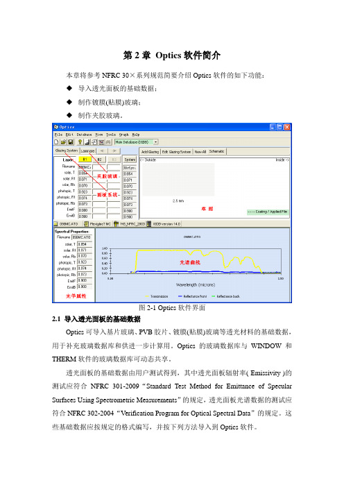
第2章Optics软件简介本章将参考NFRC 30×系列规范简要介绍Optics软件的如下功能:◆导入透光面板的基础数据;◆制作镀膜(贴膜)玻璃;◆制作夹胶玻璃。
图2-1 Optics软件界面2.1 导入透光面板的基础数据Optics可导入基片玻璃、PVB胶片、镀膜(贴膜)玻璃等透光材料的基础数据,用于补充玻璃数据库和供进一步计算用。
Optics的玻璃数据库与WINDOW和THERM软件的玻璃数据库可动态共享。
透光面板的基础数据由用户测试得到,其中透光面板辐射率( Emissivity )的测试应符合NFRC 301-2009“Standard Test Method for Emittance of Specular Surfaces Using Spectrometric Measurements”的规定,透光面板光谱数据的测试应符合NFRC 302-2004“Verification Program for Optical Spectral Data”的规定。
这些基础数据应按规定的格式编写,并按下列方法导入到Optics软件。
按“CTRL+I”组合键,或点击菜单“File→Import Text File(s)...”,打开光谱数据文件导入对话框,如图2-2所示。
选中光谱数据文件,单击打开按钮即可将光谱数据文件导入到用户数据库“user database”,Optics软件会自动将其存储到相应的分类中(Coated、Interlayer、Monolithic等),如图2-3所示。
这些文件可在制作镀膜(贴膜)玻璃或夹胶玻璃时在Add Glazing和Add Interlayer 中调用,同时还可在WINDOW和THERM软件中调用。
图2-2 光谱数据文件导入对话框图2-3 用户数据库中透光面板及其组件分类2.2 制作镀膜(贴膜)玻璃本节内容主要根据NFRC 304-2009“Creating an Applied Film Layer in Optics for NFRC Certification”编制。
微芯基MicroHAWKMV-20用户手册说明书

Specifications and OptionsNo. Function 1 Vbus (5V) 2 D – 3 D+ 4 NC 5GroundMicroHAWK ®MV –20Note: Nominal dimensions in MM are shown. Typical tolerances apply.DIMENSIONSHeight: 24 mm (0.94") Width: 34 mm (1.34") Length: 39 mm (1.54") Weight: 26 g (0.92 oz.)ENCLOSUREIP40, PlasticENVIRONMENTALOperating Temperature: 0° to 45° C (32° to 113° F)Storage Temperature: -50° to 75° C (-58° to 167° F)Humidity: 5% to 95% (non-condensing)EMISSIONSEN 55022:2010 Class A LimitsELECTRICAL5 VDC ± 5%, 350 mA at 5 VDC (typ.)CONNECTORMicro-B USBCOMMUNICATION USB 2.0 High Speed, Ethernet over USB/HID ILLUMINATIONInner Red: 4 LEDs, 625 nm nominal Inner White: 4 LEDsLight Modes: Off, On, StrobeOperating Life: 50,000 hours @ 25° CINDICATORSPower LED, 2 Target Pattern LEDs, 2 Inspection Passed Green Flash LEDsSPEED400 MHzMEMORY2 GB Non-Volatile Flash, 256 MB RAMSOFTWAREAutoVISION Sensor, AutoVISION, VisionscapeFTP IMAGE STORAGESupportedSENSOR OPTIONSWVGA (Mono): CMOS 0.34 MP (752 x 480), 4.51 x 2.88 mm, 6 μm pixel sizeSXGA (Mono): CMOS 1.2 MP (1280 x 960), 4.80 x 3.60 mm, 3.75 μm pixel sizeQSXGA (Color): CMOS 5 MP (2592 x 1944), 4.536 x 3.402 mm, 1.75 μm pixel sizeEXPOSURE TIMEWVGA: 50 to 66,667 μs SXGA: 66 to 58,825 μs QSXGA: 66 to 66,667 μsSHUTTER Global (WVGA, SXGA), Rolling (QSXGA)OPTICSStandard Density (5.2 mm), High-Density (8.0 mm), UHD (16.0 mm)FOCUSSD, HD: Factory Set to 50, 102, 190, or 300 mm UHD : Factory Set to 64 or 400 mmFRAMES PER SECONDWVGA: Up to 52SXGA: Up to 40QSXGA: Up to 5PIN ASSIGNMENTSMicro-B USB Socket©2018 Omron Microscan Systems, Inc. SP093C-EN-0518Specifications are subject to change. For complete technical information, please see the User Manual.Warranty – For current warranty information about this product, please visit /warranty.SAFETY AND QUALITY FCC, CE, UL, RoHS-Compliant QMS CERTIFICATION/qualityUltra-CompactHeight: 24 mm (0.94")Width: 34 mm (1.34")Length: 39 mm (1.54")Integrated LEDsSYMBOLOGIES2D: Data Matrix (ECC 0-200), QR Code, Micro QR Code, Aztec CodeStacked: PDF417, MicroPDF417, GS1 Databar (Composite and Stacked)Linear: Code 39, Code 128, BC412, Interleaved 2 of 5, UPC/EAN, Codabar, Code 93, Pharmacode, PLANET, POSTNET, Japanese Postal, Australia Post, Royal Mail, Intelligent Mail, KIXM icro HAWK ®MV –20 F ield oF V ieW And r eAd r Ange c HArtsWVGA Sensor Read RangesSXGA Sensor Read RangesExample Read Range:Example Read Range:Example Read Range:UHD Read RangesNote: Minimum 1D element is typically 1/2 the size of minimum 2D element. Example: 10 mil 2D = 5 mil 1D.。
举例二十种物理性质
举例二十种物理性质物理学是研究能量和物体的运动、变化的作用规律的一门科学。
物理学研究的范围很广,包括物质的结构、运动、能量、力学、声学、电磁学、温度、压力、热学、光学、原原子核物理等等。
物理性质是物质存在的基本特征,包括形状、重量、温度等。
下面我们以二十种物理性质为例,来简要了解一下物理性质的定义和特征。
1、形状(shape):指物体的外形,是物体最基本的识别标志,有正方形、圆形、椭圆形等。
2、大小(size):指物体占据的空间的大小。
大小可以确定物体的质量和密度,比如一块石头的大小比一块木头大得多,说明它的质量也更大。
3、重量(weight):指物体所具有的质量,它取决于物体的大小和密度,常用千克来表示。
4、物质(matter):是指物体所由什么组成的,它可以是气体,液体,固体等不同性质的物质组成的。
5、密度(density):指物体占据同样面积内所包含质量的多少,它取决于物体的物质组成、形状、大小等。
6、温度(temperature):温度指物体的热力,是物体状态的变化的重要指标。
它可以描述物体的温度分布,温度不同时物体的物性也各有不同。
7、质量(mass):质量是物体的另一个属性,它取决于物体的大小和密度,它可以表示物体的能量积聚、热散发等过程。
8、能量(energy):指物体存在的动能和静止能,它可以表示物体的运动情况,比如物体的加速度、热能、电能、光能等等。
9、力学(mechanics):力学是研究物体的运动、变化规律的一门学科,它可以研究物体的速度、位移、加速度等物理量的变化情况。
10、声学(acoustics):声学是研究声音的物理规律的一门学科,它可以研究声波的传播和产生过程等。
11、电磁学(electromagnetism):电磁学是研究电能、磁能、电磁场等物理量的交互作用规律的一门学科。
12、压力(pressure):指物体对周围环境产生的作用力,它是物体运动、变化、状态变化时的重要指标。
小学下册F卷英语第4单元期末试卷

小学下册英语第4单元期末试卷英语试题一、综合题(本题有100小题,每小题1分,共100分.每小题不选、错误,均不给分)1.What is the longest river in the world?A. AmazonB. NileC. YangtzeD. Mississippi答案:B2.The _______ (鸟) builds its nest high in the trees.3.The bee is busy collecting ______.4.My mom is a _____ (teacher).5.My brother is playing ________.6.The dog chases the ______ (ball).7.What do we call a scientist who studies animals?A. BotanistB. GeologistC. ZoologistD. Biologist答案:C Zoologist8.________ (植物生态监测) provides critical data.9.My dad runs a ____ (store) in our neighborhood.10. A solution is a homogeneous mixture of a solute and a ______.11.What do we call the study of the distribution and movement of populations?A. DemographyB. SociologyC. AnthropologyD. Geography答案:A12. A ________ (有机农业) avoids chemicals.13.He is a _____ (厨师) who makes delicious food.14.What do you call a baby chicken?A. DucklingB. GoslingC. ChickD. Lamb答案:C15.The __________ (历史资料) are essential for research.16.My sister is my sweet _______ who always helps me.17.The _____ (药草) has many uses in cooking and medicine.18.Which of these is a traditional Asian dish?A. PizzaB. SushiC. HamburgerD. Tacos答案:B19.How many days are there in a week?A. FiveB. SixC. SevenD. Eight20.I want to learn more about ______ (植物) and how they grow. They are very______ (重要).21.My sister is a ______. She loves to organize events.22.The teacher is _____ (kind/mean) to us.23.What do we call the process of water turning into ice?A. MeltingB. FreezingC. EvaporatingD. Condensing24.The _____ (月亮) is full tonight.25.The _____ (相互关系) between plants and animals is vital.26.The ______ (小鲸鱼) breaches the water and splashes down. It is a spectacular______ (景象).27.What do you call a baby giraffe?A. CalfB. KidC. CubD. Pup28.Planting trees can have a positive impact on reducing ______ levels in urban areas. (种树可以对减少城市地区的噪音水平产生积极影响。
场镜型号大全

场镜(f-theta镜)德国SILL OPTICS场镜(f-theta透镜)德国Sill optics生产的透镜能适用于许多激光应用领域。
产品线组合包括:标准f-theta扫描透镜(场镜)以及各种远心f-theta扫描透镜。
这些透镜主要优化波长范围为:266nm-1980nm。
1、标准ƒ-THETA透镜(场镜)型号焦距扫描范围最大入射光直径[mm]长度最大外径螺纹工作距离[mm][mm][mm][mm][mm]S4LFT0063/1266336x36835.659.2M39x1 /M55x174.5 S4LFT0101/126100.155x55104090M85x1112 S4LFT0162/126160100x100825.259.2M39x1/ M55x1179.9 S4LFT0163/126162.4107x1071243.389M85x1181.1 S4LFT3163/126163120x1201552103M85x1186.6 S4LFT2163/126163106x1062066128M85x1192.7S4LFT716316395 x 95104489M85x1197.2 S4LFT0191/126191.9125x1252057.8128 3.875“x32220.9 S4LFT0202/126*201.690x903084.1132M85x1243 S4LFT3254/126253.9115x1153075.5130M85x1297.2 S4LFT4255/126254168x1682070.1130M85x1292.7 S4LFT1254/126254.4160x1601255.3109M85x1306.3 S4LFT0300/126300175x1752078128M85x1353.1*最大远心误差为6.8°*最大远心误差为5.4°*最大远心误差为6.8°S4LFT0825/121768.6552x5521658130M102x1839.2 *最大远心误差为4.5°型号焦距扫描范围最大入射光直径[mm]长度最大外径螺纹工作距离[mm][mm][mm][mm][mm]S4LFT0375/173375.3300x3001048116M92x447.52、标准熔融石英ƒ-THETA透镜(场镜)型号焦距扫描范围最大入射光斑[mm]长度外径螺纹工作距离[mm][mm][mm][mm][mm]S4LFT0260/159260.0@1941nm160x16020182.6155M85x1120.1 S4LFT1330/159344.8@1908nm215x21520179.4163M85x1203型号焦距扫描范围最大入射光斑[mm]长度外径螺纹工作距离[mm][mm][mm][mm][mm]S4LFT3100/008115.882x8264989M85x1160.5 S4LFT0260/008264.1160x16015182.6155M85x1124 S4LFT2250/008264.7170x1701061.1105M85x1328.1 S4LFT1330/008342.2215x21520177.4163M85x1202.61064nm焦距扫描范围[mm]最大入射光斑[mm]长度外径螺纹工作距离标准型[mm][mm][mm][mm]3、超短脉冲激光器专用ƒ-THETA透镜(场镜)1030nm-1090nm焦距扫描范围[mm]最大入射光斑[mm]长度外径螺纹工作距离低吸收[mm][mm][mm][mm] S4LFT2175/328*163.494x9420110.2150M85x1205.5 S4LFT3260/328277.1142x1421561105M85x1346.1 S4LFT1330/328340215x21520174.6163M85x1203.4 S4LFT1420/328420280x2801467.7122M85x1499.2 S4LFT1500/328500340x3402068148M85x1571.3 S4LFT2500/328217.3280x28030127198M120x1620.1515nm-545nm焦距扫描范围[mm]最大入射光斑[mm]长度外径螺纹工作距离低吸收[mm][mm][mm][mm] S4LFT3100/292112.874x7454989M85x1151.5 S4LFT3260/292259.4162x1621061105M85x1325.5 S4LFT1330/292347.9212x21214108.4122M85x12794、消色差ƒ-THETA扫描透镜405nm-650nm(光学玻璃), , , ,型号焦距[mm]扫描范围最大入射光斑长度外径螺纹工作距离[mm]405nm650nm[mm][mm][mm][mm]405nm650nm S4LFT7400398.6398.670 x 7015291.7132M85x1160160。
树脂的光学设计与应用考核试卷
D.使用环境
10.下列哪些添加剂可以提高光学树脂的阻燃性?()
A.氢氧化铝
B.氢氧化镁
C.磷系阻燃剂
D.氮系阻燃剂
11.以下哪些场合需要使用高折射率的光学树脂?()
A.红外光学元件
B.高性能眼镜片
C.光学传感器
D.摄像头透镜
12.下列哪些因素会影响光学树脂的机械性能?()
A.树脂的分子结构
A.聚苯乙烯
B.聚甲基丙烯酸甲酯
C.聚乙烯
D.聚丙烯
2.光学树脂的折射率主要取决于下列哪一项?()
A.树脂的化学结构
B.树脂的分子量
C.树脂的填充物
D.环境温度
3.以下哪种方法常用于改善光学树脂的耐热性?()
A.增加分子量
B.添加紫外线吸收剂
C.使用交联剂
D.提高加工温度
4.在光学设计中,以下哪个因素通常不影响树脂透光率?()
答案:_____________,_____________
6.光学树脂的__________和__________是评价其耐环境性能的重要指标。
答案:_____________,_____________
7.在制造光学元件时,__________和__________是常见的成型方法。
答案:_____________,_____________
树脂的光学设计与应用考核试卷
考生姓名:________________答题日期:____年__月__日得分:_____________判卷人:_____________
一、单项选择题(本题共20小题,每小题1分,共20分,在每小题给出的四个选项中,只有一项是符合题目要求的)
1.下列哪种树脂具有最高的透明度?()
CZ-V20系列数字RGB光滑度传感器头用户手册说明书
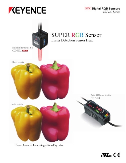
NEWDigital RGB SensorsCZ -V20 SeriesSUPER R G B SensorLuster Detection Sensor HeadDetect luster without being affected by colorLuster Detection Sensor HeadCZ -H72Digital RGB Sensor AmplifierCZ -V20Glossy objectsMatte objectsLUSTERUnaffected by colored patterns or print below a glossy surfaceThe CZ-H72 can reliably detect targets by their luster level, without being affected by colors or printDigital display indicates gloss levels Easy setup with dual digital displayThe measured value and the setting value can be viewed simultaneously. In addition, the sensitivity can be easily fine-tuned with a touch of a button.*The glossy level may vary depending on printing ink or paper quality.21Industrial firstFastest in its classFILM mode for detecting presence/absence of films (Patent pending)The amplifier features a built-in FILM mode, which can be selected for difficult detection of such targets as packaging films for cigarettes or Compact Discs. These films exhibit birefringence, which can prevent stable detection in conventional photoelectric sensors.World's firstAll the features you need for stable luster detectionConventional photoelectric sensors can't come closeAmplifier for luster detection sensorLuster Detection Sensor HeadCZ-H72Digital Color Sensor Amplifier for Luster Detection SensorCZ-V21A (P ) [Main unit ]CZ-V22A (P ) [Expansion unit ]GlossyMatteOne touch tuningOne touch of a button completes sensitivity settingElectrical connector (Receiver) 4 outputs x 2ch HeatsinkFiber cable (Transmitter)size of theconventional models Lighter and smaller sensor head (Patent pending)Light is emitted using a fiberoptic cable. Designing the light emitting electronics in the amplifier, rather than the sensor head, results in a significant size reduction.Detecting presence/absence of wrapping film Small beam spot SmallLargeLarge beam spotSelectable beam spot sizeChoose from 0.12" (3 mm) or 0.20" (5 mm)diameter beam spots (when detecting from 0.59" (15 mm))Note: Total detecting range is from 0.39" to 0.79" (10 to 20 mm)Detecting presence/absence of adhesive on targetsIt extracts only the luster component from the target's surfaceMost targets reflect both regular and diffuse light components. The special luster capturing optics in the CZ-H72 sensor head extract only the luster component and eliminate the undesirable effects of diffuse reflections.Response frequency 200µsMost levels in its classOne unit can detect 4 differentglossy levelsDetecting presence/ absence of adhesive agent on targetsDetecting presence/absence of sealing tapePackagingDetecting defect of shrink packagingElectric/Electronic industryAutomotive/MetalAutomotive/MetalPlastic/MoldingDetecting presence/absence of plating at contact pointsDetecting presence/absence of plating(low temperature)Detecting presence/absence of flat paint on plasticsDetecting presence/absence of hot-melt coating/adhesive agentLuster Detection Sensor Head ----- Applications in various industriesDetects presence/absence of sealing tape. It stably detects patternedtransparent sticker without being affected by background colors or patterns.Detects presence/absence of transparent film. It can stably detect targets without being affected by vibration.Detects shrink film wrapping defects. FILM mode reduces dual refraction from films to stably detect targets.Detects presence/absence of plating electrodes. With selectable large/small beam spots, it can stably detect small targets.Detects presence/absence of plating. It digitally indicates luster level. Sensitivity setting or fine adjustment are easily performed with simple push buttons.Detects presence/absence of adhesive. The sensor head is half the size of conventional models, enabling more flexible mounting.Detects different types of molded articles by checking presence/absence of flat paint. It can recognize up to 4 different types of targets without tooling Detects presence/absence of hot-melt coating. It stably detects targets without being affected by the targets' colors or patterns.Specifications Input/output circuit* CZ-V21/ V21A/V21P/V21AP only Output circuitCZ-V21/V22/V21A/V22A * CZ-V21/V21A onlyCZ-V21P/V22P/V21AP/V22AP * CZ-V21P/V21AP only2.When several units are connected, the acceptable ambient temperature varies depending on the conditions given below. To connect several units, be sure to mount them to a DIN rail and to limit the output current to a maximum of 20 mA. When 1 or 2 units are connected: -10 to +50°C (14 to 122°F) When 3 units are connected: -10 to +45°C (14 to 113°F)Note:The expansion unit of the FS-V20 Series cannot be connected to the main unit of the CZ-V20 Series. To connect the FS and CZ Series units, connect the expansion unit of the CZ-V20 Series to the main unit of the FS-V20 Series. To connect two or more expansion units, connect the CZ-V20 Series units on the right of the FS-V20 Series units.DimensionsCZ-H72When the mounting bracket is attachedUnit: inch mmWhen sensor head rotated at 45° clockwiseWhen sensor headrotated at 45° counterclockwiseLuster canceling diffuse reflectiveLong detection distance diffuse reflectiveCZ-H35SCZ-H37SUnaffected by surface conditionssuch as warpage, vibration, inclination of luster3 Adjustable beam spotsDigital R G B Sensor Line-upFluorescence detection UV sensorIt radiates ultraviolet to detect fluorescent substances Small beam spot of 0.04" (1 mm) dia. at setting distance 0.63" (16 mm)CZ-H35S/ CZ-H37SDetects subtle difference of colors or patterns. Unaffected by a target’s luster.CZ-H32Can be mounted at a distance from targets. Unaffected by vibration.CZ-H52Unaffected by patterns or colors of targets to detect fluorescent。
- 1、下载文档前请自行甄别文档内容的完整性,平台不提供额外的编辑、内容补充、找答案等附加服务。
- 2、"仅部分预览"的文档,不可在线预览部分如存在完整性等问题,可反馈申请退款(可完整预览的文档不适用该条件!)。
- 3、如文档侵犯您的权益,请联系客服反馈,我们会尽快为您处理(人工客服工作时间:9:00-18:30)。
图 4-20:左,矩孔;右该矩孔的夫琅禾费衍射条纹。衍射装置如图 4-19。特点: 孔径越宽,衍射光场能量集中得越窄;孔径越窄,衍射光场能量散布得越宽。可 以预测一下,单缝衍射条纹的形状如何吗?
通信:zmh@ - 36 -
光学讲义 安徽大学 2013-2014 年秋季学期
光学讲义 安徽大学 2013-2014 年秋季学期
(续)讨论:具有一定缝宽的杨氏双缝在此装置下,条纹分布如何?
F
b=f a
θ θ
x
关于几道习题: 例 15:如 4-25:
f
d 2 d 2
sin
π aθ 2π d λ e j λ 2θ π aθ λ
cos
2
a
2
sin
π aθ λ
π aθ 2π d λ e− j λ 2 θ
通信:zmh@ - 46 -
通信:zmh@
- 45 -
光学讲义 安徽大学 2013-2014 年秋季学期
光学讲义 安徽大学 2013-2014 年秋季学期
(3)主极大
(4)次级大及其位置
图 4-28:条纹中最亮的位置称“主极大” 。出现在衍射条纹的正中。这恰恰是几 何光学预言的像点。 几何光学不正确的地方, 在于它不能预言像点附近也存在光 场分布。事实上,除了主极大,还有次级大…
通信:zmh@
- 40 -
光学讲义 安徽大学 2013-2014 年秋季学期
光学讲义 安徽大学 2013-2014 年秋季学期
4.3.3 单缝衍射因子的特点
极值 条件 :
d sin δ 2
δ 2
( ) = 0 ⇔ (δ 2) cos (δ 2) − sin (δ 2) = 0, (δ ≠ 0) ; (δ 2 )
sin
π aθ λ
π aθ λ
2
。被包络的明暗相间的条纹,cos
2
2π b πb θ θ ∝ 1 + cos λ λ
,恰
sinα 图 4-35:单元衍射因子为 α ,缝间干涉因子为1+ejβ + ej3β; 故其衍射场为 sinα jβ j3β α (1+e + e ) ,其模即为书上的答案。
- 47 -
光学讲义 安徽大学 2013-2014 年秋季学期
光学讲义 安徽大学 2013-2014 年秋季学期
例 8(思考题 4-19)在弗朗禾费衍射中,为保证在衍射场中至少出 现强 度的 一级 极小 ,单 缝的 宽度 不能 小于 多少 ?
(5) 讨论:如果单缝沿垂直于主光轴的平面内移动,条纹如何移 动?
光学讲义 安徽大学 2013-2014 年秋季学期
光学讲义 安徽大学 2013-2014 年秋季学期
(1)暗斑位置
(2)亮斑的角宽度
图 4-26:考察衍射因子,知其为 0 的位置在δ = ±2π, ±4π, … ±2nπ…处。这跟刚 才用半波带法给出一个唯像的解释完全一致。
图 4-27:相邻暗条纹的角距离作为其间亮条纹的角宽度。特别地,零级亮斑的 λ 角宽度为:2·a ,为其他亮条纹宽度的 2 倍。
通信:zmh@ - 33 -
1 透镜后焦平面上的图案由___点和副___点 图 4-18:夫琅和费衍射印象。请讨论○ 2 图案中唯一的___点应来自于透镜前_________于主轴的_______光;众 构成;○ 3 焦平面的 多的副___点分别来自于透镜前______后不平行于主轴的_______光。 ○ 图案上,有的位置亮,有些位置暗。这些点子的位置,代表其对应的平行光的 ______,它们的亮暗,代表其对应平行光的________。 请务必清晰的理解上述物理图像。 本节只研究单缝和矩孔的衍射。 下面将开始实 际的内容。
通信:zmh@ - 37 -
δ=
3π
L or Δ
= 3λ
f
图 4-22:用半波带法可以粗略预测:当焦平面考察点距单缝边缘的位相差相差 3π,5π…时,此时等效半波带剩余仅仅一个,能观察到亮纹;相差 2π,4π…时, 相当于半波带两两抵消,只能观察到暗条纹。这样的分析正确吗?为什么?
2
F
sin
π π π sin aθ aθ 2π d sin aθ − j 2π d θ λ e λ 2 =4 λ λ e j λ 2θ + π π π aθ aθ aθ λ λ λ
2
πa sin x 2 π 2π d λf dθ ∝ x 1 + cos πa λ λf x λf
图 4-34:结论。具有一定缝宽的杨氏双缝,其弗朗禾费衍射条纹的包络为构成 其的单缝的衍射条纹
1.5π
2.5π
δ/2
y = tan δ 2
( )
y =δ 2
通信:zmh@ - 43 -
图 4-25:衍射光场(强度)随单缝上下边缘光场振幅叠加时相位差之半(δ/2) δ 的变化。此处的2 可折算成衍射角(及其正弦) 、屏幕的位置等物理量。
通信:zmh@
- 44 -
j sinα 图 4-36:单元衍射因子依然为 α ,缝间干涉因子变为1 + e λ
为间距为 b,而缝宽为零的理想杨氏双缝在此光路下的干涉条纹。
通信:zmh@
- 53 -
通信:zmh@
- 54 -
光学讲义 安徽大学 2013-2014 年秋季学期
光学讲义 安徽大学 2013-2014 年秋季学期
例 16:又如 4-26:
例 17:再如,4-27:2N 条平行狭缝:
量的计算方法如图。 单缝衍射因子。还 记得之前在哪见过 吗?
通信:zmh@ - 41 -
( )
- 42 -
的交 点。
通信:zmh@
光学讲义 安徽大学 2013-2014 年秋季学期
光学讲义 安徽大学 2013-2014 年秋季学期
y
-2.5π
-1.5π
−π/2 0 π/2
θsinfFra bibliotekπa θ λ
πa θ πb λ e−j λ θ
d 2
sin
πa θ πb λ ej λ θ πa θ λ
F
1 两个 图 4-32:如前所述,此杨氏双缝在焦平面F 上的的条纹是这样产生的:○ 各自的场表达式为图中的式子所描述。 (可 单缝各自的光扰动衍射至焦平面F 上, 以看出,二者模平方完全相同,因而条纹形状和位置相同。但各自场的相位并非 2 上述上述两个衍射场相干叠加。请见下页… … 一样) ;○
sin
图 4-33: (续)上述两个场量 π a θ 、 π a θ
λ λ
πa θ λ
sin
πa θ πb λ e−j λ θ
相加后(! )再取模平方,才
(! )是条纹的强度分布。
通信:zmh@ - 52 -
通信:zmh@
- 51 -
光学讲义 安徽大学 2013-2014 年秋季学期
图 4-29:对单缝衍射因子求导并令之为 0,可求出次级大的位置(当然,已包含 δ 主极大位置) 。他们是2 = ±1.43π, 2.46π, 3.47π…这跟刚才用半波带法预言这些次 级大出现的位置只是近似,为什么?哪个更严格?
通信:zmh@ - 48 -
通信:zmh@
通信:zmh@
- 38 -
光学讲义 安徽大学 2013-2014 年秋季学期
光学讲义 安徽大学 2013-2014 年秋季学期
4.3.2 单缝衍射的强度公式
(1)矢量图解法
图
1 单缝上边 4-23:屏幕上衍射角为 θ 处的点 Pθ 处的相对光强可按如下思路。○
π 2 据此,可认为从 A 缘 A 与下边缘 B 的光场传播至 Pθ 处时的相位差为2λ asinθ ;○
光学讲义 安徽大学 2013-2014 年秋季学期
(2)单缝的夫琅禾费衍射图样及特点
图 4-21:单缝(实际上是比较狭长的矩孔)的夫琅禾费衍射图样,衍射装置图 依旧如图 4-19。当照明光源为点光源时,衍射图样如中,当照明光源为平行于 狭缝的线状光源时,衍射条纹如右。二者的共性是,衍射条纹垂直于狭缝方向的 强度分布相同,如最右边蓝色曲线所示。下面将先定性分析亮、暗条纹的位置, 然后在 4.3.2 节定量分析该强度分布。
光学讲义 安徽大学 2013-2014 年秋季学期
光学讲义 安徽大学 2013-2014 年秋季学期
4 .3 夫 琅 禾 费 单 缝 衍 射 和 矩 孔 衍 射
前面已经介绍过菲涅尔衍射和夫琅禾费衍射的异同。 对于前者, 我们已经探讨了 圆孔、圆屏衍射中,轴上强度的分布规律。至于轴外强度的分布,由于不具备稳 定性,且稍复杂。我们在普通光学中就不讨论了。 但对于夫琅和费衍射,则不然。夫琅和费衍射场可认为是一系列平面波的迭加, 衍射条纹的强度分布, 恰恰代表了衍射源的 “平面波组分” 的权重分布。 其本质, 是衍射源场的傅里叶变换。这在光学中占有举足轻重的地位。 下面试图通过一个“八一”军徽的夫琅和费衍射图样,来建立起夫琅禾费衍射物 理内涵的印象。对单缝衍射和矩孔衍射条纹的理解,应比这个例子更简单,需要 熟练掌握。
图 4-30。为保证在衍射场中至少出现强度的一级极小,单缝的宽度不能小于一 个波长。同样的道理,对于类似“视场中最多能出现几条亮条纹、几条暗条纹” 的问题也应掌握计算的方法。
通信:zmh@ - 49 -
图 4-31:答: (1)和(2)各自单独开放时,条纹位置重合;故此装置中,衍射 条纹不随单缝的垂直移动而移动。但各自的场量(图中的数学表达式)的相位不 相同,因此当两缝同时开放时,会产生干涉条纹,而非仅仅是两个衍射条纹的简 单叠加。
通信:zmh@ - 50 -
... ...
光学讲义 安徽大学 2013-2014 年秋季学期
光学讲义 安徽大学 2013-2014 年秋季学期
