MCNNINCH Copyright Workshop Sept 7, 2002, Toronto, Canada
[讲稿]IconWorkshop使用技巧新手篇教程
![[讲稿]IconWorkshop使用技巧新手篇教程](https://img.taocdn.com/s3/m/ac88849cb8d528ea81c758f5f61fb7360b4c2b8a.png)
IconWorkshop使用技巧新手篇教程IconWorkshop是一款专业的功能强大的图标制作工具,Axialis IconWorkshop的简称。
基于行业标准为Windows,MacOS和工具栏等创建,编辑,转换图标的软件。
允许高效率地工作,并在几分钟内创建专业的图标。
拥有强大的编辑器,能够创建毫无质量损失的各种图像格式的图标。
下面,由我来为大家详细介绍一下这款软件的一些使用技巧。
一、制作Windows Vista图标1.创建一个256x256像素的图像,Axialis IconWorkshop兼容的文件格式有:BMP,PNG,PSD,JP2000。
也可以结合Adobe Photoshop插件创建一个图标,或是通过组合多个图像对象。
在这个教程中,我们将使用图像down.png。
可以点击下载,也可以在管理器重查找:对象/Pack2。
如果对象包不存在,可以在IconWorkshop中文网站下载。
2.启动IconWorkshop,打开图像文件。
3.选择整个图像。
选择编辑/选择全部或按Ctrl + A组合键。
现在已经选择矩形周围绘制的图像。
选择文件/创建Windows 图标或按Ctrl+Shift+Y,打开创建从图像新建windows图标对话框,允许创建所有图标格式:4.点击选择图像格式。
要创建一个Windows Vista的图标,不要忘了添加256×256的Windows Vista格式的RGB / A 、256色以及16色模式。
要创建一个完全兼容Windows Vista的图标,需要选中Windows Vista的PNG压缩256x256格式。
以及添加平滑/锐化滤镜效果所产生的图像中的RGB / A模式。
单击确定,完成Windows Vista图标制作。
5.所有可用的格式被显示在左侧列表中。
可以选择它们来编辑或预览,添加/删除图标项目等。
6.只有256x256的格式可以压缩,可以通过选择“绘图/PNG压缩图像格式(Windows Vista)或者按K键来添加/删除选项。
MCNP简介
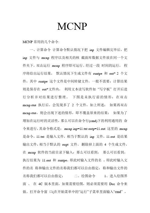
MCNPMCNP常用的几个命令:一、计算命令计算命令默认情况下把inp 文件编辑完毕后,把inp 文件与mcnp 程序以及相关的核截面库数据文件放在同一个文件夹下,双击运行mcnp 程序即可运行。
经过一段时间的运行,程序将给出运行结果,默认情况下生成文件有runtpe 和out* 2 个文件,其中runtpe 这个文件是中间转储文件,一般不需要;计算结果则是保存在out*文件内,利用文本读写软件如“写字板” 打开后进行分析并对结果进行整理。
下图是未执行前的情形:在双击mcnp.exe 执行后,会发现多了2 个文件,如上所述:如果再双击mcnp.exe,则会出现下述的情形,即不覆盖原来的结果:如果为了增加在运行时的灵活性,那么可以在命令行(cmd)下的利用通用的命令来进行,其命令格式是:mcnp inp=11.txt outp=11.out 这里的mcnp 是命令,11.txt 是输入文件,相当于默认的inp 文件,11.out 是结果输出文件,相当于默认的oupt 文件。
删除掉上面的4 个生成文件,在mcnp 软件的当前目录下输入:那么可以看到,那么可以看到,执行结果为11.out 和runtpe,即此时输入文件的名,即此时输入文件的名称和输出文件的名称我们都可以自由指定:称和输出文件的名称我们都可以自由指定:二、绘图命令1、进入绘图界面、在4C 版本里面,如果需要绘图,则必须需要用Dos 命令来做。
打开命令窗口(在开始菜单中的“运行”子菜单里面输入“cmd” ,回车),利用“cd”命令进入MCNP 程序所在目录(建议MCNP 所在的文件夹路径要尽量短并且文件夹名称为英文名称),输入MCNP IP 命令,此时系统会自动给你打开MCNP 的绘图命令窗口:MCNP 的操作界面,在主窗口里会出现 2 个子窗口,名称分别为MCNP Execute Window(命令窗口)和MCNP Plot Window(绘图窗口),如上图所示,用户在命令窗口中输入各种绘图命令和相关参数,MCNP 将把执行结果显示在绘图窗口中。
ASUS CREATOR CENTER 用户指南说明书

1CREATOR CENTER for Creation NOTEBOOK2ContentsAbout CREATOR CENTER (4)CREATOR CENTER Basics (5)Main Screen (5)Information Bar (5)Main Menu (6)Sub Menu (6)Creative Applications Optimization (7)Creator Mode (7)How to Enable Creator Mode (8)User Scenario (9)Selecting User Scenario (9)General Settings (10)Monitor (11)True Color (12)True Color Preset Options (12)Mystic Light (13)Voice Command (16)Noise Cancellation (21)Duet Display (22)Create a New Screen Profile (23)Activating Duet Screen Capture (23)Gaming Gear (24)Product Registration (25)Live Update (26)System Info (27)Microsoft APP (28)Battery Master (29)Calibrating Battery (29)Backup (30)Notices (31)Copyright (31)Revision History (31)3ContentsAbout CREATOR CENTER∙Optimize performance for creative applications.∙System performance tuning—you can choose overclock or silent.∙Monitor system information.∙Adjust the best display settings for your eyes.∙Register your MSI products.∙Control LED light effects and synchronize effects to your devices.∙Use utilities to control special features.∙Set the charging method and calibrate the battery.∙Backup system.⚠ImportantTHE SOFTWARE FEATURES IN THIS USER GUIDE VARY BY PRODUCT.THE SCREENSHOTS FOR THE UI IN THIS USER GUIDE ARE FOR REFERENCE ONLY AND THE ACTUAL UI DESIGN MAY VARY.4About CREATOR CENTER5CREATOR CENTER Basics CREATOR CENTER Basics Main Screen⚠Important The screenshots for the UI in this user guide are for reference only and the actual UI design may vary.Operation PanelInformation Bar Display System Profile Picture/Login/ Logout Display Creator Mode Status.Main MenuSub Menu Information Bar Display MSI product currently in use. Click to enter the control page.Display mode currently applied. Switch between different modes by selecting a mode from the drop-down menu.6CREATOR CENTER BasicsSub MenuMain MenuHomeMy DeviceSupportToolsSettingCollapse Button7Creative Applications Optimization Creative Applications OptimizationThe Creator Mode feature will optimize the computer system, monitor, cooler and other peripherals to provide the best experience while using creative applications.Creator Mode Creator Mode main switchSelect Creator Mode in the sub menu to enter Creator Mode control panel You can drag and drop to set the priority List software that supported by creator modeEdit the software listRefresh the software listAdd software to the software listCreator Mode selection User Priority Mode: User-defined software priority Real-Time Mode: Automatically optimize software performance.8Creative Applications OptimizationHow to Enable Creator Mode You can enable the Creator Mode for Processor Affinity, System Performance and Application Priority while using creative applications.1.Go to Home > Creator Mode, and turn on Creator Mode main switch.Turn on Creator Mode main switch2.Select User Priority Mode or Real-Time Mode.Check the box Check the boxor3. Run the application.⚠ImportantIn order to apply the settings, the creator mode must be enabled before running the software.9User Scenario User Scenario Selecting User Scenario The CREATOR CENTER has default scenarios and customized preset options.1. Go to Home > User Scenario.2. Select one of the options. ▪Extreme Performance – A configuration that boosts the highest possible performance. ▪Balanced - MSI recommended settings for average users. ▪Silent - A configuration that allows system to run smoothly with minimum loading. ▪Super Battery - A power-saving mode that lowers the power consumption forbasic needs.Adjust Panel Brightness, Keyboard Brightness and Fan Speed for each scenario.Click to reset to defaultGeneral SettingsYou can enable/disable some general settings in this panel.⚠ImportantThe features in the General Settings vary by product.Windows Key - Click to enable or disable the Windows key on the keyboard. Switch Key - Click to switch the Windows key and the Fn key on the keyboard. WebCam - Click to enable or disable the webcam.Display OverDrive - Only available on certain displays. Once enabled, the response time of the will be overclocked.USB Lighting - Control the USB port lighting mode.GPU Switch - Click to switch the MSHybrid Graphics Mode and the Discrete Graphics Mode.Crosshair Display - Click to enable or disable the Crosshair Display. Click the gear icon to open the True Color control and choose the type of crosshair and its color.10General Settings11Monitor Monitor Monitor feature provides a custom hardware monitor gadget to display the system status.Click to free up memory Click to clean up the disk Select Monitor in the sub menu to enter Monitor page12True ColorTrue Color With True Color function, you can adjust the best screen gamma, saturation, brightness and contrast settings for your eyes.The Ture Color feature supports games in windowed mode.Select True Color in the sub menu to enter True Color control panelSelect the quick screen color optionTrue Color Preset Options When you click the preset option, the screen settings will be immediately applied to your computer. The detailed options are as follows: ⚠Important The features in the True Color vary by product. ▪Gamer - For playing games. ▪Anti-Blue - For reducing the amount of blue light that is emitted from the display to reduce eye fatigue. ▪sRGB - For accurate color when viewing images on websites. ▪Designer - For design applications.▪Office - For office and productivity applications.▪Movie - For watching movies. ▪AdobeRGB - For accurate color when viewing images and other media created in the Adobe RGB color space. ▪Display P3 - For accurate color in wide-gamut cinema mode. ▪Customize - For the True Color 3 application setting.13Mystic Light Mystic Light Mystic Light feature allows you to control LED light effects of MSI & partner products. For some earlier products, you can go to product download page to download the applicable LED control software. ⚠ImportantThe Mystic Light feature is only available when MSI Gear devices are connected.When you click the Apply button, the LED effect settings can be saved to Profile1~3, and you can switch to different settings by clicking Profile1~3.Device synchronizationClick to access Ambient Link All Synchronization LED item drop-down menu Light effect, LED color, speed and brightness lever selectors Apply buttonVoice Command14Mystic Light∙Device synchronization - In this section, you may synchronize LED light effect to your devices.Chain icon - indicates the device has been synchronized.Broken-chain icon - indicates thedevice is not synchronized.Device icon - click it to change LED effect setting for this device. When the device icon turns blue, it indicates the device you’re currently setting.▪Individual - You can also change settings for one single device. To do that, click the chain icon and the color will turn gray as below.▪To synchronize devices - Click the chain icon above device icon. When the chain icon turns blue, it indicates that the device has synchronized LED effect settings with other devices.▪All synchronization - Click the big chain icon on the left side of all the devices.Click the big chain icon∙LED item drop-down menu - Click it to select the LED item on the device. The LED effects vary depending on your LED item selection.15Mystic Light ∙Light effect drop-down menu Click it to select LED light effects. Please note that the options about light effects would be more or less depending on the devices you have. It will only list the light effects which are available for all applicable devices.∙LED Color selector - In this section, you may select the color for one single light effect (Stack, Breathing, Flashing etc.).The outer arc is a custom color picker and the inner arc is the default color picker that cannot be changed. You can simply change the LED color by clicking on the color on the outer or inner arc. To store a custom color, click one of the color slotson the outer arc to store the color of your choice.Use the Hue Circle to choose the color you want. The color you choose will be displayed on the center circle.You can specify a color by editing an RGB (red, green, blue) color value between 0 and 255.Drag the brightness slider up to increase brightness or drag down to decrease brightness. ∙Effect speed and brightness levelDrag the sliders to adjust the LED light effect for switching speed and light brightness.Please note that these function will only be available if your device supports it.Voice CommandMystic Light allows you to use your voice to change LED effects.⚠ImportantThe Voice Command feature is only available for the Notebook with the Per Key RGB keyboard or connected to MSI Gear devices.To start Voice Command, you need to install Windows 10 Speech Voices.1. Go to Windows Settings, and select Time & Language.2. Select Add a preferred language, then add English and the voice packages.3. Change your default speech options to English by selecting Speech.16Mystic Light17Mystic Light How to Control Mystic Light via Voice Command Go to Home > Mystic Light, and click setting in the upper right corner. Enable Voice Command and then you can change the LED style by saying Hey Lucky.Click hereEnable Voice CommandA list of Hey Lucky commands Click to open the list of Hey Lucky commands18Mystic LightAmbient Link With the Ambient Link feature, it will provide visual color feedback on Philips Hue and Nanoleaf depending on what is happening in games. To use Ambient Link, you need to follow the instructions below to complete the link setup.⚠ImportantThe Ambient Link feature is only available for the Notebook with the Per Key RGB keyboard or connected to MSI Gear work Requirements ∙The router is broadcasting a 2.4GHz network. ∙The Wi-Fi network is using WPA/WPA2 security.∙The router is configured for any of the Wi-Fi modes a/b/g/n.Philips Hue Setup (optional)1. Plug in your Hue bridge and it will automatically power up.2. Connect it to the router LAN port.3. Wait for the two lights to come on and you are good to go. (Left is power light and center is local network Nanoleaf Setup (optional) ∙The router is compatible with Bonjour (mDNS).Click to enter the Ambient Link control panelSelect Mystic Light in the sub menu to enter Mystic Light menu19Mystic Light Ambient Link Control PanelGame Mode and Ambient Mode can only be activated one at a time on the Ambient Link control panel.∙Game Mode tab Click to synchronize/ non-synchronize the game Synchronization main switch Click to access the game control panelBack Select Game Event, color and brightnessPreview the effect Apply changes20Mystic Light∙Ambient Mode tab∙Ambient Link tabClick to select an effect asbackground lightClick to switch to PhilipsHue and Nanoleaf Status indicator Click to detectdevicesClick tosynchronize Re-synchronize Removethe device Adjust orientation orpositionApply changesPreview the effectON/OFF backgroundlight & musicDrag the slider to adjust lightbrightness21Noise Cancellation Select Noise Cancellation in the sub menu to enter MSI Sound Tune panel Enable/ Disable Speaker Noise Cancellation.Enable/ Disable Microphone Noise Cancellation.Select Microphone (MSI Sound Tune) in the communication software.Select Speaker (MSI Sound Tune) in the communication software.Noise Cancellation The AI-powered noise cancellation is trained through a deep neural network (DNN), the model is generated with more than 500 million data, simulates the way the human brain works. When a sound is heard, the model automatically recognizes and separates the vocal sound from background noises. Hence, filtering out all the unwanted noise. This feature greatly improves the users’ communication experience.22Duet DisplayDuet Display Duet turns your iOS device & Android phone, tablet, or Chromebook into the most advanced extra display, and offers unparalleled performance and display quality.Click to open the Duet Display introduction window Duet Display InstructionsiOS mode Scan the QR code to download Duet Coach app on your iOS device and follow the app instructions to mirror screen.Screen Profiles Hotkey SettingClick to review the screen profile for 5 seconds Click to remove the screen profileCreate a New Screen Profile1. Connect to a second display.2. Click the New button.3. Enter the name of this new profile and click the Apply button.4. Drag through the portion of the display you want to capture.5. Click the Next Segment button to set maximum 3 segments.6. Click the Done button.Activating Duet Screen Capture1. Connect to a second display.2. Check the hotkey setting of the screen profile and remember it.3. Run the application.4. Press the hotkey and the selected portion will be projected on to the second display.23Duet Display24Gaming GearGaming Gear This panel allows you to control MSI’s gaming gear and supported third-party devices. ⚠ImportantThe Gaming Gear feature is only available when MSI Gear devices are connected.Select Gaming Gear in the sub menu to enter Gaming Gear menu Supported devices will be displayed here. Click the device to enter the control panel of the device.25Product Registration Product RegistrationRegister your MSI product to get exclusive updates, quicker service and product support.Login to your MSI account on this My Devices tab. If you don’t have an MSI account, please click the Join MSI Member button or use Facebook/ Google Plus to login.Click the Product Register button and fill in the product registration form.Select My Device in the sub menuto register your product26Live UpdateLive UpdateLive Update feature allows you to scan system and download the latest drivers and utilities. With Live Update, you don’t need to search the drivers on websites. Live Update will download the appropriate drivers automatically. Some software/ drivers will be installed automatically after downloading, please follow the instructions of the installer.To use Live Update:1. Connect your computer to the internet. 2.Go to Support > Live Update.Select which item you want to update Click to scan the systemUtility and driver listClick to install27System Info System Info The System Info provides information about OS, Product Name, Serial Number and Software information.To open System Info:1. Go to Support > System Info.To export system information:1. Go to Support > System Info.2. Click Export System Info button in the upper right corner.3. Browse to the location where you want to save the new text file, and then click Save.To send the serial number to MSI online customer service:1. Go to Support > System Info.2. Click Content Transfer button in the upper right corner.3. Follow customer service’s instructions, and enter 5-digit encryption code.System InformationClick to export system information to a text file.Click to send the serial number of the laptop to MSI online customer service.28Microsoft APPMicrosoft APPThe Microsoft App feature detects installed drivers and displays a relative Microsoft application download links.To install Microsoft App:1. Go to Support > Microsoft App.2. Click the Get it from Microsoft icon on the right side of the item.3.Download and install the application from Microsoft Store.Click to install29Battery Master Battery Master Battery Master is a function tab related to battery maintenance such as RemainBattery Percentage, Battery Health Option, and Battery Calibration.Battery Health Option - Select the battery charging capacity Remain battery percentage Click to calibrate the batteryCalibrating Battery We recommends doing Battery Calibration every 3 months to have the best battery life.1. Go to Tools > Battery Master.2. Click the Battery Calibration icon.3. Follow the instructions on the Battery Calibration screen to connect to the power adapter, install the battery and close the other windows.4. Click Start.30BackupBackupBackup utility designed to backup the recovery image to a USB flash disk or ISO files. They can be used to recover the system to manufacturer’s default settings when it is needed.⚠ImportantUsage of this application on any product with no authorization may be prohibited.Select to create arecovery USB flashdiskSelect to create anISO image fileAfter choosing the type ofbackup, click Next to start thebackup process.NoticesThe MSI logo used is a registered trademark of Micro-Star Int’l Co., Ltd. All other marks and names mentioned may be trademarks of their respective owners. No warranty as to accuracy or completeness is expressed or implied. MSI reserves the right to make changes to this document without prior notice.Copyright© Micro-Star Int’l Co.,Ltd. 2020 All rights reserved.Revision HistoryVersion 1.0, 2020/11, First release31Notices。
肯为旎免费办公平台安装使用说明

肯为旎免费办公平台安装:
1. 下载本软件。
2. 然后解压缩,其中包含有两个文件,一个是肯为旎免费办公平台安装使用说明,另一个是安装文件,您可以参照说明文件,然后双击安装文件并选择安装路径即可安装。
3. 您有三种方法可启动本平台: 第一种方法是点击桌面的快捷图标;第二种方法是从开始菜单中选择程序;第三种方法是如果您在本次开机中运行过本平台,您可以直接在浏览器地址栏中输入http://localhost 。
v3.3.2以后版本增加了通讯录分组功能,增加了分组查看、多选发送电子邮件、多选发送短信等功能,让您维护客户更容易。
v3.3.3以后版本增加了通讯录按品牌导入导出功能、鼠标悬停显示手机号码和电子邮件功能,操作更简单。
v3.3.6以后版本增加了上传文件编码格式的自动检测功能和自动转码为UTF-8功能,使用通讯录导入更简单。
对于端口80、443或3306被占用的解决方法:先关闭占用端口80、443或3306的软件,然后运行肯为旎免费办公平台,等本平台启动后,再打开占用端口80或3306的软件即可,比如迅雷。另,需要注意是您不能再启动IIS或其他mysql数据库。
附:查看80的端口的方法说明(443、3306类似):
2.2 发送电子邮件和接收功能让您发送与接收电子邮件更简单、快捷。一键收取多个邮箱邮件并将接收人设置为同一人的功能,让您的邮件接收速度更快、效率更高,彻底免去多个邮箱多次登录收取邮件的麻烦!
V3.2以后版本新增加电子邮件漂流功能,您发送的电子邮件不知道将漂向何方,被何人捡到,充满着未知的神秘气息。快来玩吧。
2. 沟通交流方式十分丰富,轻松实现有效沟通。提供多种交流工具,比如短信、电子邮件、网络电话、聊天室、站内消息(或称局域网邮件)等等,实现各部门、各角色、各人间的顺畅沟通。
BANNERsnack:在线制作Flash Banner
BANNERsnack:在线制作Flash Banner/用BANNERsnack制作Banner的操作过程非常简单,而且不需要下载软件,也不需要付费就能制作出自己喜欢的Banner。
的网站或博客带来不错的视觉效果,但传统FIash软件的制作流程比较复杂,还需要下载庞大的安装软件。
这时,你不妨去BANNERsnack上看看,它支持免费的FlashBanner在线制作,可以为你省去不少麻烦。
BANNERsnack是一款强大的线上Flash横幅广告制作工具,它提供的Banner制作工具非常容易上手。
感觉与PowerPoint的制作过程差不多,就算你没有制作F10sh的基础,也能够轻松地制作出swf 格式的Bonner动画。
用户可以直接在BANNERsnack上寻找自己喜欢的Banner模板进行修改,或是从零开始逐步制作自己喜欢的样式。
首先,打开BANNERsnack的网站首页,在点击“M0keaBanner’’按钮之后,网站就会弹出注册提示。
用户在完成注册之后,将会自动进入制作界面,点击“CreatenewBanner”按钮,会弹出Banner的设置界面,在这里用户可以选择Banner的尺寸和背景颜色设置。
遗憾的是,免费用户只能选择14种Banner 尺寸,而收费用户则可以自定义Banner的尺寸,定制背景颜色。
点击“Settings”按钮,用户还可以选择颜色和图片来装饰背景。
接下来就可以开始编辑Banner了,BANNERsnack右侧的页面是编辑Banner各种属性和效果的导航条。
其中“Addtext’’意为增加文字,但不支持中文;“Addimage”是指增加图片,用户可以直接上传图片;“Te对”与“lmaqe”分别是编辑文字与图片的各种属性;“Filters”的意思是增加各种特效,BANNERsnack 提供了闪烁,倒影、阴影等多种效果;“Bullain”和“Buildout”可以设置图片或文字进出时的特效。
印能捷Connect工作流程系统(版本5.0)Workshop用户指南简体中文(下册)
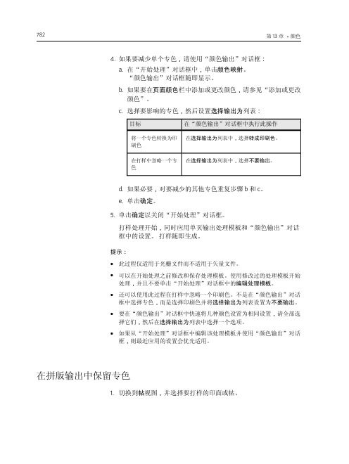
在最终输出中保留专色
785
目标
选择此选项
保留一个专色
分离
(只有在处理模板的输出转换部分选择了制作色 版复选框, 该色版才会分色输出。)
在打样中忽略一个 颜色
不要输出
c. 单击确定。
3. 通过将选定的印面或帖拖到拼版输出处理模板,对这些印面或帖 开始拼版输出处理。
4. 通过设置处理模板中的一个选项而保留所有其他专色: a. 在开始处理对话框中,单击编辑处理模板。 b. 展开输出转换部分。 c. 在输出分色处理列表中,选择全部分色输出。 d. 关闭该处理模板。
关于无专色扩展颜色管理
791
输出 输出
输出
列出已在页面颜色 列表中对每种颜色指定的颜色输出处理 办法。
选择输出为
指定希望 Prinergy 如何输出每个颜色。在页面颜色栏中选 择一种或多种颜色后,列表会显示以下选项: ● 分离
输出专色。对于最终输出,Prinergy 会将专色作为分色 输出。对于拼版输出,如果在输出分色处理框中选择 输出所有分色,印能捷会将专色作为分色输出。
b. 选择专色,然后在选择输出为列表中选择一个选项:
要完成此操作
选择此选项
将一个专色转换为印 刷色
转成印刷色或一个印刷色
将一个专色映射为另 一个颜色
专色或印刷色
(如果该颜色已经不存在,首先添加一个分 色。)
788
第 13 章 -颜色
要完成此操作 保留颜色
选择此选项
分离 (只有在处理模板的输出转换部分选择了制作 色版复选框,该色版才会分色输出。)
3. 通过清除处理模板中的一个选项而保留专色: a. 在开始处理对话框中,单击编辑处理模板。 b. 展开输出转换部分或颜色转换部分。 c. 在颜色库区域中,清除始终使用颜色组合器来转换专色复选 框。 d. 关闭该处理模板。
WorkShopManager自动化工具说明书
WorkShopManagerWorkShopManager offerS neW poSSibilitieSIt is generally thought that automated production is complicated to introduce and that it can only be appliedto long runs. The may be true when the robot grips the workpiece directly, but hardly when the workpiece is palletised.The handling units in System 3R’s automation programs are all intended to move pallets between a magazine and predefined chucks in one or more machines. When you work with pallets, the preparations are the same whether you are producing 100 different parts or 100 parts of the same type. When you have made the preparations for production in WorkShopManager, the operation of lifting the pallet into and out of the machine is not complicated at all. WorkShopManager has been developed …… to simplify the preparations for production in automatic cells… to maximise production capacity… to create the greatest possible flexibility… to ensure the security of the process. WorkShopManager is equally useful for manual loading of pallets in a single machine as for automatic production in a seven-axis linear robot cell, since this software grows with the task. Start with a single machine on the lowest level and then upgrade as your business develops.WorkShopManager SecureS the proceSSThe core of the system is a central database. All clients, machines and automation devices are in constant contact with the database.WorkShopManager links all machining processes together in a controllable and clearly-arranged production system. All machining data is available to the machines and can easily be transferred to the right machine at the right moment.User-friendly – necessary data are entered quickly and ina structured mannerQuick, precise overview of the entire process chainGreat flexibility – the order of priority can be changed at any timeSimpler, safer preparation of automatic cells. Information about workpieces, magazine positions, offset values and NC programs is always available.The risk of errors due to the human factor is minimised.Generates shorter lead timesGreater process securityOffers the possibility of automated one-piece productionJob status and machining times are recorded and stored in the database.Reports such as machining time per workpiece can be generated and transferred to a planning system.Alarm messages from machines and robots can be transferred via e-mail or SMS.All information about the machining is brought together in WorkCenter, which communicates with the database.In the database, a manufacturing order is created. This may contain:• an operation list• an NC program for the operation in question • documents linked to the operations • pallet identity • offset valuesWorkCenter does not produce its own data; it compiles information for every machining operation.The necessary information is fetched from the database and transferred to the machines.How the relevant order is executed depends on the type of cell…… manual creation of a batch with BatchBuilder, or … automatic execution with CellManager.A batch is a complete machining operation, containing several manufacturing orders with their magazine positions. This type of magazine loading can be regarded as static, since machining of the entire batch must be completed before changes can be made in the magazine.With CellManager, each individual job is startedaccording to a priority list. Here, you can change priorities and magazine content while the machine is working.EXECUTIONThe user-friendly procedure in WorkShopManager can be summarised in three stages: preparation, execution and monitoring.PREPARATIONSMONITORINGOrder creationIn WorkCenter, manufacturing orders can beorganised in accordance with the company’sstandard order structure.A manufacturing order covers one or moreidentical parts which may be located on one ormore pallets. The same pallet may also be carryingdifferent parts, each with its own manufacturingorder. This open structure offers great flexibilitywhen creating a manufacturing order.Article registerThe operation list can be saved as an article foruse if the part needs to be produced again. If anew order is created, based on an article, everymachining step and NC program will be present inthe new production order.Simpler and quickerReduces the risk of data entry errorsOption –planning system integrationWhen information is imported from ERP/MPS, amanufacturing order is created automatically.What then remains to be done is to place theworkpiece on its pallet, to identify it and to fetch anyoffset values from the measuring machine.Up-to-date machining information is fed back toERP/MPS for evaluation and post-calculation.IdentifyThe next step is to link the physical objects with their manufacturing orders.The object is mounted on a pallet with a code carrier which is recorded in the database.All information held in the database for that object can now be M integrationIf required, a measuring machine can be used before machining to determine offset values (X-Y -Z-C) for the workpiece on its pallet.The measurements are stored in a neutral format. They are then adapted and transferred to the machine tool.Reduces the risk of data entry errors Multi-pallet functionThere is no need to measure objects on multi-pallets. Every fixture on the pallet has a knownposition, and this automatically gives the objects the correct offset values.With this function, users can create their own multi-palletsEspecially suitable for milling applications Quality controlWhen the measuring machine has performed a geometrical inspection of the object and sent the status to the database, the object can be barred or released for further operations.Operation listsIn an operation list, the order of the variousmachining steps is defined. One operation must be complete before the next operation can start.DocumentsDocuments – machining instructions, reports,images, etc. – can be linked to every operation. This allows the operator to make use of the information directly at the machine.No searching for informationThe information is linked to the right machining operationIf the operation has been saved as an article, information from previous occasions will be available.Linked ordersFor an EDM operation, electrodes need to beproduced. Linking electrode manufacturing with the EDM operation minimises the risk of mistakes. As soon as the electrode blank has been identified on its holder, the electrode and the EDM operation are linked.The right electrode for the right EDM operation High process safety StatusThe status – waiting / machining / ready – of every object in the magazine is recorded in the database.cellManagerCellManager, which requires the pallets to have an identification system, manages the entire robot cell, handling all necessary data automatically. The cell is controlled entirely from the screen.• Starts the robot’s ID cycle.• Manages the pallet ID codes and magazine positions.• Displays the magazine content graphically.• Creates priority lists.• Automatically starts available jobs in the order of the priority list.• Updates the information in the database with the status and machining times of individual orders.Identification systemWhether you work with visual identification such as labels, or an electronic system with inductive readers and ID transponders, CellManager ensures the security of the process.Chaotic magazine loadingOn loading, the pallet is placed at the first available free magazine position.CellManager MultiManages a robot cell consisting of one robot and more than one machine, regardless of the type and make of the machines.Easy to change prioritiesThe order of priority of jobs can be changed while the machine is working.Easy to insert new jobsFinished workpieces can be lifted out of the magazine and new ones loaded into it, while the machine is working.Manually loaded machinesChaotic loading of a machine table with multiple chucks.After manual scanning of the machine table, a job list is created in CellManager. The jobs are then done in the sequence in the job list – one program at a time. The job sequence can be changed Automatic monitoringRobot-loaded machinesChaotic loading of the magazinesAfter automatic scanning of the magazine, a job list is created in CellManager.The jobs are then done in the sequence in the job list – one program at a time.The job sequence can be changed Automatic monitoringThe magazines can be lifted out and loaded while the machine is working.EXECUTION EXECUTION EXECUTION EXECUTION EXECUTIONEXECUTION EXECUTION EXECUTION EXECUTION EXECUTIONBatchBuilderBatchBuilder is a WorkCenter function for creating a complete machining operation – en batch – made up of several individual orders. You choose a number of orders and add magazine positions. The function then generates a main program with associated subprograms. The batch is transferred to the right machine and when the machine is started, the individual machining operations are executed – from the beginning to the end.Magazine positionsThe NC programs that were linked to the respective operation do not include the magazine positions. This information therefore must therefore beadded when the batch is created. This can be done manually or the information can be generated automatically.Simplified NC-programming.Loading listWhen the batch has been created, you can print out a loading list which describes the magazine positions of the objects.Less risk of loading at the wrong magazine positionTransfer of NC programsWhen creating the batch, you choose the machine or the cell that you want to perform the machining operation. The complete information is then transferred via the network. The magazines are loaded according to the loading list and the machining operation can start.Option – automatic electrode selection (AES)Automatically chooses the best electrode for the machining operation. Used to limit the number of electrodes when producing identical workpieces. However, for this function it is necessary to make an estimate of the electrode wear with coarse, intermediate and fine machining.You can, for instance, choose to “downgrade” the electrodes after the first bit. For the second bit you then use the first intermediate electrode for the coarse machining, the first fine electrode for the intermediate machining, and a new electrode for the fine machining.Option – cutting tool control (CTC)This function checks that all cutting tools that are needed for the milling operatins are available before machining starts.Option – RobotManagerOption for cells with industrial robot: CellManager handles communication between the various units of the cell, coordinates all activities, and monitors the status of every operation.MONITORING MONITORING MONITORING MONITORING MONITORINGCellManagerCellManager maintains constant contact with themachines and monitors what is happening in thecell.• When a machining operation starts and ends• What operation is being done• What object is in the machine• Messages coming from the maskinOption – AlarmServerAlarm messages from the machine and the robotcan be transferred via e-mail or SMS.WorkCenterAll information about the various operations issaved in the database. WorkCenter makes itpossible to use this information wherever youhappen to be.ReportingReports such as machining time per part can becreated and transferred to a production planningsystem (PPS).StatusWorkCenter keeps track of what is to be machined,and on which machine, as well as monitoring thestatus of jobs.Option –planning system integrationUp-to-date machining information can beautomatically fed back to ERP/MPS for evaluationand post-calculation.ModuleS in WorkShopManagerexaMpleS of applicationS1011baSic configurationSWorkShopManager is equally useful for manual loading of pallets in a single machine as forautomatic production in a seven-axis linear robotcell, since it grows with the task. Start with a single machine on the lowest level and then upgrade as your business develops.T -2219-E 08.05 S u b j e c t t o m o d i fi c a t i o n s • S y s t e m 3R , a m e m b e r o f t h e G e o r g F i s c h e r G r o u p .Combi, Delphin, Dynafix, Locx, LX, Macro, One Minute Set-Up, One System Partner, R2R, System 3R, VDP , WorkMaster, WorkPal, WorkPartner, WorkShopManager, 3HP , 3R, 3Ready-To-Run and 3Refix are registered trademarks of System 3R.EUROPESystem 3R Europe GmbH Wasserweg 19DE-64521, GROSS-GERAU tel +49 61 52 80 02 0fax +49 61 52 80 02 35**************************Chech Republic & SlovakiaSystem 3R Czech Tiskarska 10/257CZ-108 28 PRAHA 10tel +420 234 054 224fax +420 234 054 225**********************France & PortugalSystem 3R France56 Boulevard de Courcerin Les Espaces Multiservices 15F-77183 CROISSY BEAUBURG tel +33-01 60 95 90 80fax +33-01 60 37 88 16**************************Germany & BeNeLuxSystem 3R Deutschland Wasserweg 19DE-64521, GROSS-GERAU tel +49 61 52 80 02 0fax +49 61 52 80 02 35**************************Italy & SpainSystem 3R Italia Via Ponchielli, 2/4IT-20063 CERNUSCO SUL NAVIGLIO (MI)tel +39 02 92 38 821fax +39 02 92 11 23 19**************************ScandinaviaSystem 3R Nordic Sorterargatan 1SE-162 50 VÄLLINGBY tel +46-08 620 20 00fax +46-08 38 81 84**************************Järfälla Härdverkstad Elektronikhöjden 8SE-175 43 JÄRFÄLLA tel +46-08 580 125 50fax +46-08 580 126 55*****************Switzerland & AustriaSystem 3R Schweiz AG Wilerstrasse 98CH-9230 FLAWIL tel +41-071 394 13 50fax +41-071 394 13 60**************************Turkey & BulgariaSystem 3R TürkiyeAbdi Ipekci Cad. Ozel Idare Is Merk 150/209Bayrampasa 34030 ISTANBUL tel +90-212 613 8062-8063fax +90-212 613 8069******************************United KingdomSystem 3R UKRedvale House, New RoadPRINCES RISBOROUGH, Buckinghamshire HP27 0JN United Kingdom tel +44-01844 27 44 55fax +44-01844 34 88 00**************************ASIAFar East, China & IndiaSystem 3R Far East Pte.Ltd.6 Harper RoadLeong Huat Building, 01-01SINGAPORE SG-369 674tel +65-6289 4811fax +65-6289 3011**************************Shanghai Contact Office tel +86-21 6432 7927fax +86-21 6432 7928**************************Beijing Contact Office tel +86-10 8225 1632fax +86-10 8225 1635Guangdong Contact Office tel +86-769 8162 0628fax +86-769 8162 0638Malaysia Contact Office tel +60-03 7877 4785fax +60-03 7877 5948Taiwan Re gional Office tel +886-02 2278 3126fax +886-02 2278 3108Thailand Contact Office tel / fax +66-2 6422 764Japan & KoreaSystem 3R Japan CO., Ltd.Kaki Building2-5-22, Suido, Bunkyo-ku TOKYO JP-112-0005tel +81-03 5840-7383fax +81-03 5848-8723**************************Nagoya Regional Office tel +81-052 774 6250fax +81-052 774 6285Osaka Regional Office tel +81-06 6396 1500fax +81-06 6396 2855AMERICASystem 3R USA Inc.Headquarters & Technical Center 915 Busse RoadELK GROVE VILLAGE, US-IL 60007tel +1 847 439 4888fax +1 847 439 5099e-mail:********************Canada & Eastern MI116 Lynngate PlaceLondon Ontario Canada N6k 1S5Canadatel +1 519 870 8339, +1 248 320 1016 e-mail:***********************AZ, CA, CO, ID, MT, NM, NV, OR, TX, UT, WA, WY & Mexico1241 Celery LaneCorona, US-CA 91719Tel +1 909 226 1042e-mail:**********************1524 Valley Dr.Norco, US-CA 92860tel +1 714 299 4923e-mail:***************************IA, MN, ND, NE, SD & WI915 Busse RoadElk Grove Village, US-IL 60007tel +1 847 439 4888, +1 630 240 9825fax +1 847 439 5099e-mail:************************AR, IN, KY, OH & TN8466 Hill Pine CourtIndianapolis, US-IN 46227tel +1 317 215 4039, +1 317 694 7508fax +1 317 215 4041e-mail:*************************AL, FL, GA, LA, MS, NC & SC20934 Orchard Town nd O Lakes, US-FL 34638tel +1 813 326 0125e-mail:**************************IL, KS, MO, OK & Western MI915 Busse RoadElk Grove Village, US-IL 60007tel +1 847 439 4888, +1 630 240 9824fax +1 847 439 5099e-mail:******************************NJ, NY & PA67 Forest DrivePompton Plains, US-NJ 07444tel +1 201 248 3885e-mail:**************************CT, DC, DE, MA, MD, ME, NH, RI, VA, VT & WV915 Busse RoadElk Grove Village, US-IL 60007tel +1 847 439 4888, +1 201 214 7088fax +1 847 439 5099e-mail:************************System 3R International ABSorterargatan 1, SE-162 50 VÄLLINGBYtel+46-086202000,fax+46-087595234,e-mail:*****************,。
MCNP4c中文教程
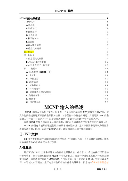
MCNP输入的描述___________________________________________________ 1Ⅰ. INP文件_________________________________________________________________ 1A.信息块__________________________________________________________________ 1B.初始运行________________________________________________________________ 2C.接续运行________________________________________________________________ 2D.卡片格式________________________________________________________________ 3E.粒子标识符 ______________________________________________________________ 6F.缺省值 __________________________________________________________________ 6G.输入错误信息 ____________________________________________________________ 6H.检查几何错误____________________________________________________________ 6Ⅱ. 栅元卡 __________________________________________________________________ 7Ⅲ. 曲面卡 __________________________________________________________________ 9A.由方程定义曲面__________________________________________________________ 9B .用点定义对称曲面 _____________________________________________________ 12C.由三个点定义一般平面__________________________________________________ 13Ⅳ.数据卡_____________________________________________________________ 13A. 问题类型(MODE)卡_________________________________________________ 14B. 几何卡_______________________________________________________________ 14C . 降低方差 ____________________________________________________________ 19D. 源的描述_____________________________________________________________ 27E 记数指定卡__________________________________________________________ 41F.材料指定卡__________________________________________________________ 62H.能量和热处理方式指定 ________________________________________________ 67I.问题截断卡 ___________________________________________________________ 71J.外围卡_______________________________________________________________ 73K.用户数据组 __________________________________________________________ 73MCNP输入的描述MCNP的输入包括几个文件,但主要一个是由用户填写的INP(缺省文件名)文件,该文件包括描述问题所必需的全部输入信息。
Company-presentation-template公司演示英文模板
Design inspiration For presentation
Powerpoint is a complete presentation graphic package it gives you everything you need to produce a professional-looking presentation
Stylish design
Slide main title
Design inspiration For presentation
Our user-friendly and functional search engine helps you locate the right templates, effectively saving your time.
Slide main title
Design inspiration For presentation
Our user-friendly and functional search engine helps you locate the right templates, effectively saving your time.
Our user-friendly and functional search engine helps you locate the right templates, effectively saving your time.
Stylish design
Stylish design
Stylish design
Slide main title
Design inspiration For presentation
SONAR7官方中文手册

Cakewalk SONAR 7官方中文手册美国Cakewalk公司 原著云天音乐网 饶磊 编译云天音乐网()版权所有 抄袭必究本文档所涉及的信息如有更改,孰不另行通知,Twelve Tone Systems公司不承担相应的义务。
此文档所描述的软件仅授权给已经合法取得许可证的用户使用。
软件只能在协议条款规定的范围内使用和复制。
除非协议特别允许,任何媒体复制该软件均属非法。
在没有得到Twelve Tone Systems 公司书面许可的任何情况下,本文件不得以任何形式、任何理由(电子的或机械的)进行复制或传播,包括复印和录制。
Copyright © 2007 Twelve Tone Systems, Inc. 版权所有。
ACID是Sony公司的注册商标。
Cakewalk是Twelve Tone Systems公司的注册商标。
SONAR和Cakewalk标志是Twelve Tone Systems公司的注册商标。
其它的公司和产品名称均是其拥有者的商标。
在互联网上访问Cakewalk英文站:。
在互联网上访问Cakewalk中文站:。
在互联网上访问云天音乐网:。
SONAR 7 官方中文手册0.目录0. 目录 (3)1. 编者的话 (6)2. 中文SONAR系列图书 (7)3. 前言 (9)4. SONAR 7 介绍 (11)7 新特性概览 (12)4.1. SONAR7 的系统需求 (13)4.2. SONAR4.3. SONAR7 新特性详解 (13)7 的峰值限制器-Boost 11 (17)4.4. SONAR7 包含的虚拟乐器 (17)4.5. SONAR4.6. SONAR7 的母带后期处理插件 (19)7Producer Edition(制作人版)和Studio Edition(工作室版)功能比较 (21)4.7. SONAR4.8. 选择SONAR 7的20个理由 (21)5. 安装 (28)6. 指南 (38)6.1. 指南1——基础 (39)6.1.1. 打开工程 (39)6.1.2. 回放准备 (39)6.1.3. 播放工程 (42)6.1.4. 自动重新开始工程 (44)6.1.5. 更改速度 (46)6.1.6. 静音和独奏 (47)6.1.7. 更改音轨乐器 (48)6.1.8. 在MIDI键盘上演奏音乐 (49)6.2. 指南2——录制MIDI (51)6.2.1. 创建新工程 (51)6.2.2. 录制MIDI音轨 (51)6.2.3. 保存 (54)6.2.4. 循环录制 (54)6.2.5. 插入录制 (56)6.3. 指南3——录制数字音频 (58)6.3.1. 设置采样率 (58)6.3.2. 设置音频驱动器的精度和录制精度 (58)6.3.3. 新建一个工程 (59)云天音乐网()版权所有 抄袭必究6.3.4. 设置音频轨 (59)6.3.5. 检查输入电平 (59)6.3.6. 录制数字音频 (60)6.3.7. 聆听录制结果 (60)6.3.8. 录制另外一个动机 (61)6.3.9. 输入监听 (61)6.3.10. 循环和插入录制 (62)6.3.11. 多通道录制 (62)6.4. 指南4——编辑MIDI (63)6.4.1. 移调 (63)6.4.2. 用托放的方法复制事件条 (63)6.4.3. 在钢琴卷帘视图里编辑音符 (64)6.4.4. 滑动编辑 (65)6.4.5. 绘制MIDI包络线 (66)6.4.6. 把MIDI转换成音频 (67)6.5. 指南5——编辑数字音频 (69)6.5.1. 打开工程 (69)6.5.2. 导入音频文件 (69)6.5.3. 移动以及循环事件条 (70)6.5.4. 对事件条进行滑动编辑 (70)6.5.5. 自动交叠淡变 (71)6.5.6. 合并音轨 (71)6.6. 指南6——使用智能事件条 (72)6.6.1. 添加智能事件条到工程里 (72)6.6.2. 循环智能事件条 (73)6.6.3. 更改智能事件条的音高 (75)6.6.4. 更该工程的速度 (76)6.6.5. 创建你自己的智能事件条 (76)6.7. 指南7——混音 (80)6.7.1. 添加实时的音频效果 (80)6.7.2. 对单独的效果设置自动控制 (80)6.7.3. 编组控制 (81)6.7.4. 对混音自动控制 (81)6.7.5. 导出MP3文件 (82)6.8. 指南8——使用软件合成器 (84)6.8.1. 把Cakewalk TTS-1插入到工程里 (84)6.8.2. 通过软件合成器播放MIDI音轨 (85)6.8.3. 将软件合成器音轨转换成音频 (85)6.9. 指南9——鼓映射 (87)SONAR 7 官方中文手册6.9.1. 创建一个新工程 (87)6.9.2. 创建鼓映射 (87)6.9.3. 创建一条鼓音轨 (87)6.9.4. 映射鼓音符到不同的输出端口上 (88)6.10. 指南10——Cyclone软件合成器 (91)6.10.1. Cyclone概述 (91)6.10.2. 添加文件到节奏垫 (91)6.10.3. 设置节奏垫的音量和相位 (92)6.10.4. 演奏Cyclone (92)6.10.5. 在循环编辑器里编辑循环 (93)7. 版权说明 (95)云天音乐网()版权所有 抄袭必究1.编者的话云天音乐网()是专门从事电脑音乐研究和教学的专业网站,自从2000年开办以来一直得到广大电脑音乐爱好者的喜爱。
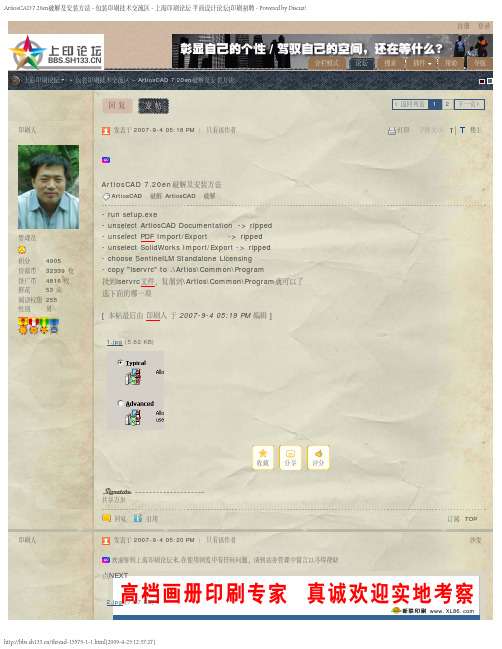
ArtiosCAD.7.20en破解及安装方法
TOP 9#
/thread-15575-1-1.html[2009-4-25 12:37:27]
ArtiosCAD 7.20en破解及安装方法 - 包装印刷技术交流区 - 上海印刷论坛 平面设计论坛|印刷招聘 - Powered by Discuz! 管理员
积分
哎,包装软件怎么这么不好下载呢!
初学乍练
积分
9
资源币 200 枚
推广币 0 枚
鲜花
0朵
阅读权限 10
shihuanyu
回复
引用
发表于 2008-2-2 07:24 PM | 只看该作者
没有找到lservrc 文件,谁告诉在哪里呢,我看下载的文件夹里面没有呢.
初学乍练
积分
9
资源币 200 枚
推广币 0 枚
分栏模式
论坛
搜索
插件
帮助
导航
返回列表 1 2 下一页
打印 字体大小:
楼主
管理员
积分
4905
资源币 32339 枚
推广币 4816 枚
鲜花 53 朵
阅读权限 255
性别 男
ArtiosCAD 7.20en破解及安装方法
ArtiosCAD , 破解 ArtiosCAD , 破解
- run setup.exe - unselect ArtiosCAD Documentation -> ripped
我装了起动不了,太可惜了.
渐入佳境
积分
168
资源币 246 枚
推广币 1 枚
鲜花
0朵
阅读权限 30
guise4543
回复
引用
发表于 2007-9-26 11:06 AM | 只看该作者
Native Instruments MASCHINE MIKRO MK3用户手册说明书
The information in this document is subject to change without notice and does not represent a commitment on the part of Native Instruments GmbH. The software described by this docu-ment is subject to a License Agreement and may not be copied to other media. No part of this publication may be copied, reproduced or otherwise transmitted or recorded, for any purpose, without prior written permission by Native Instruments GmbH, hereinafter referred to as Native Instruments.“Native Instruments”, “NI” and associated logos are (registered) trademarks of Native Instru-ments GmbH.ASIO, VST, HALion and Cubase are registered trademarks of Steinberg Media Technologies GmbH.All other product and company names are trademarks™ or registered® trademarks of their re-spective holders. Use of them does not imply any affiliation with or endorsement by them.Document authored by: David Gover and Nico Sidi.Software version: 2.8 (02/2019)Hardware version: MASCHINE MIKRO MK3Special thanks to the Beta Test Team, who were invaluable not just in tracking down bugs, but in making this a better product.NATIVE INSTRUMENTS GmbH Schlesische Str. 29-30D-10997 Berlin Germanywww.native-instruments.de NATIVE INSTRUMENTS North America, Inc. 6725 Sunset Boulevard5th FloorLos Angeles, CA 90028USANATIVE INSTRUMENTS K.K.YO Building 3FJingumae 6-7-15, Shibuya-ku, Tokyo 150-0001Japanwww.native-instruments.co.jp NATIVE INSTRUMENTS UK Limited 18 Phipp StreetLondon EC2A 4NUUKNATIVE INSTRUMENTS FRANCE SARL 113 Rue Saint-Maur75011 ParisFrance SHENZHEN NATIVE INSTRUMENTS COMPANY Limited 5F, Shenzhen Zimao Center111 Taizi Road, Nanshan District, Shenzhen, GuangdongChina© NATIVE INSTRUMENTS GmbH, 2019. All rights reserved.Table of Contents1Welcome to MASCHINE (23)1.1MASCHINE Documentation (24)1.2Document Conventions (25)1.3New Features in MASCHINE 2.8 (26)1.4New Features in MASCHINE 2.7.10 (28)1.5New Features in MASCHINE 2.7.8 (29)1.6New Features in MASCHINE 2.7.7 (29)1.7New Features in MASCHINE 2.7.4 (31)1.8New Features in MASCHINE 2.7.3 (33)2Quick Reference (35)2.1MASCHINE Project Overview (35)2.1.1Sound Content (35)2.1.2Arrangement (37)2.2MASCHINE Hardware Overview (40)2.2.1MASCHINE MIKRO Hardware Overview (40)2.2.1.1Browser Section (41)2.2.1.2Edit Section (42)2.2.1.3Performance Section (43)2.2.1.4Transport Section (45)2.2.1.5Pad Section (46)2.2.1.6Rear Panel (50)2.3MASCHINE Software Overview (51)2.3.1Header (52)2.3.2Browser (54)2.3.3Arranger (56)2.3.4Control Area (59)2.3.5Pattern Editor (60)3Basic Concepts (62)3.1Important Names and Concepts (62)3.2Adjusting the MASCHINE User Interface (65)3.2.1Adjusting the Size of the Interface (65)3.2.2Switching between Ideas View and Song View (66)3.2.3Showing/Hiding the Browser (67)3.2.4Showing/Hiding the Control Lane (67)3.3Common Operations (68)3.3.1Adjusting Volume, Swing, and Tempo (68)3.3.2Undo/Redo (71)3.3.3Focusing on a Group or a Sound (73)3.3.4Switching Between the Master, Group, and Sound Level (77)3.3.5Navigating Channel Properties, Plug-ins, and Parameter Pages in the Control Area.773.3.6Navigating the Software Using the Controller (82)3.3.7Using Two or More Hardware Controllers (82)3.3.8Loading a Recent Project from the Controller (84)3.4Native Kontrol Standard (85)3.5Stand-Alone and Plug-in Mode (86)3.5.1Differences between Stand-Alone and Plug-in Mode (86)3.5.2Switching Instances (88)3.6Preferences (88)3.6.1Preferences – General Page (89)3.6.2Preferences – Audio Page (93)3.6.3Preferences – MIDI Page (95)3.6.4Preferences – Default Page (97)3.6.5Preferences – Library Page (101)3.6.6Preferences – Plug-ins Page (109)3.6.7Preferences – Hardware Page (114)3.6.8Preferences – Colors Page (114)3.7Integrating MASCHINE into a MIDI Setup (117)3.7.1Connecting External MIDI Equipment (117)3.7.2Sync to External MIDI Clock (117)3.7.3Send MIDI Clock (118)3.7.4Using MIDI Mode (119)3.8Syncing MASCHINE using Ableton Link (120)3.8.1Connecting to a Network (121)3.8.2Joining and Leaving a Link Session (121)4Browser (123)4.1Browser Basics (123)4.1.1The MASCHINE Library (123)4.1.2Browsing the Library vs. Browsing Your Hard Disks (124)4.2Searching and Loading Files from the Library (125)4.2.1Overview of the Library Pane (125)4.2.2Selecting or Loading a Product and Selecting a Bank from the Browser (128)4.2.3Selecting a Product Category, a Product, a Bank, and a Sub-Bank (133)4.2.3.1Selecting a Product Category, a Product, a Bank, and a Sub-Bank on theController (137)4.2.4Selecting a File Type (137)4.2.5Choosing Between Factory and User Content (138)4.2.6Selecting Type and Character Tags (138)4.2.7Performing a Text Search (142)4.2.8Loading a File from the Result List (143)4.3Additional Browsing Tools (148)4.3.1Loading the Selected Files Automatically (148)4.3.2Auditioning Instrument Presets (149)4.3.3Auditioning Samples (150)4.3.4Loading Groups with Patterns (150)4.3.5Loading Groups with Routing (151)4.3.6Displaying File Information (151)4.4Using Favorites in the Browser (152)4.5Editing the Files’ Tags and Properties (155)4.5.1Attribute Editor Basics (155)4.5.2The Bank Page (157)4.5.3The Types and Characters Pages (157)4.5.4The Properties Page (160)4.6Loading and Importing Files from Your File System (161)4.6.1Overview of the FILES Pane (161)4.6.2Using Favorites (163)4.6.3Using the Location Bar (164)4.6.4Navigating to Recent Locations (165)4.6.5Using the Result List (166)4.6.6Importing Files to the MASCHINE Library (169)4.7Locating Missing Samples (171)4.8Using Quick Browse (173)5Managing Sounds, Groups, and Your Project (175)5.1Overview of the Sounds, Groups, and Master (175)5.1.1The Sound, Group, and Master Channels (176)5.1.2Similarities and Differences in Handling Sounds and Groups (177)5.1.3Selecting Multiple Sounds or Groups (178)5.2Managing Sounds (181)5.2.1Loading Sounds (183)5.2.2Pre-listening to Sounds (184)5.2.3Renaming Sound Slots (185)5.2.4Changing the Sound’s Color (186)5.2.5Saving Sounds (187)5.2.6Copying and Pasting Sounds (189)5.2.7Moving Sounds (192)5.2.8Resetting Sound Slots (193)5.3Managing Groups (194)5.3.1Creating Groups (196)5.3.2Loading Groups (197)5.3.3Renaming Groups (198)5.3.4Changing the Group’s Color (199)5.3.5Saving Groups (200)5.3.6Copying and Pasting Groups (202)5.3.7Reordering Groups (206)5.3.8Deleting Groups (207)5.4Exporting MASCHINE Objects and Audio (208)5.4.1Saving a Group with its Samples (208)5.4.2Saving a Project with its Samples (210)5.4.3Exporting Audio (212)5.5Importing Third-Party File Formats (218)5.5.1Loading REX Files into Sound Slots (218)5.5.2Importing MPC Programs to Groups (219)6Playing on the Controller (223)6.1Adjusting the Pads (223)6.1.1The Pad View in the Software (223)6.1.2Choosing a Pad Input Mode (225)6.1.3Adjusting the Base Key (226)6.2Adjusting the Key, Choke, and Link Parameters for Multiple Sounds (227)6.3Playing Tools (229)6.3.1Mute and Solo (229)6.3.2Choke All Notes (233)6.3.3Groove (233)6.3.4Level, Tempo, Tune, and Groove Shortcuts on Your Controller (235)6.3.5Tap Tempo (235)6.4Performance Features (236)6.4.1Overview of the Perform Features (236)6.4.2Selecting a Scale and Creating Chords (239)6.4.3Scale and Chord Parameters (240)6.4.4Creating Arpeggios and Repeated Notes (253)6.4.5Swing on Note Repeat / Arp Output (257)6.5Using Lock Snapshots (257)6.5.1Creating a Lock Snapshot (257)7Working with Plug-ins (259)7.1Plug-in Overview (259)7.1.1Plug-in Basics (259)7.1.2First Plug-in Slot of Sounds: Choosing the Sound’s Role (263)7.1.3Loading, Removing, and Replacing a Plug-in (264)7.1.4Adjusting the Plug-in Parameters (270)7.1.5Bypassing Plug-in Slots (270)7.1.6Using Side-Chain (272)7.1.7Moving Plug-ins (272)7.1.8Alternative: the Plug-in Strip (273)7.1.9Saving and Recalling Plug-in Presets (273)7.1.9.1Saving Plug-in Presets (274)7.1.9.2Recalling Plug-in Presets (275)7.1.9.3Removing a Default Plug-in Preset (276)7.2The Sampler Plug-in (277)7.2.1Page 1: Voice Settings / Engine (279)7.2.2Page 2: Pitch / Envelope (281)7.2.3Page 3: FX / Filter (283)7.2.4Page 4: Modulation (285)7.2.5Page 5: LFO (286)7.2.6Page 6: Velocity / Modwheel (288)7.3Using Native Instruments and External Plug-ins (289)7.3.1Opening/Closing Plug-in Windows (289)7.3.2Using the VST/AU Plug-in Parameters (292)7.3.3Setting Up Your Own Parameter Pages (293)7.3.4Using VST/AU Plug-in Presets (298)7.3.5Multiple-Output Plug-ins and Multitimbral Plug-ins (300)8Using the Audio Plug-in (302)8.1Loading a Loop into the Audio Plug-in (306)8.2Editing Audio in the Audio Plug-in (307)8.3Using Loop Mode (308)8.4Using Gate Mode (310)9Using the Drumsynths (312)9.1Drumsynths – General Handling (313)9.1.1Engines: Many Different Drums per Drumsynth (313)9.1.2Common Parameter Organization (313)9.1.3Shared Parameters (316)9.1.4Various Velocity Responses (316)9.1.5Pitch Range, Tuning, and MIDI Notes (316)9.2The Kicks (317)9.2.1Kick – Sub (319)9.2.2Kick – Tronic (321)9.2.3Kick – Dusty (324)9.2.4Kick – Grit (325)9.2.5Kick – Rasper (328)9.2.6Kick – Snappy (329)9.2.7Kick – Bold (331)9.2.8Kick – Maple (333)9.2.9Kick – Push (334)9.3The Snares (336)9.3.1Snare – Volt (338)9.3.2Snare – Bit (340)9.3.3Snare – Pow (342)9.3.4Snare – Sharp (343)9.3.5Snare – Airy (345)9.3.6Snare – Vintage (347)9.3.7Snare – Chrome (349)9.3.8Snare – Iron (351)9.3.9Snare – Clap (353)9.3.10Snare – Breaker (355)9.4The Hi-hats (357)9.4.1Hi-hat – Silver (358)9.4.2Hi-hat – Circuit (360)9.4.3Hi-hat – Memory (362)9.4.4Hi-hat – Hybrid (364)9.4.5Creating a Pattern with Closed and Open Hi-hats (366)9.5The Toms (367)9.5.1Tom – Tronic (369)9.5.2Tom – Fractal (371)9.5.3Tom – Floor (375)9.5.4Tom – High (377)9.6The Percussions (378)9.6.1Percussion – Fractal (380)9.6.2Percussion – Kettle (383)9.6.3Percussion – Shaker (385)9.7The Cymbals (389)9.7.1Cymbal – Crash (391)9.7.2Cymbal – Ride (393)10Using the Bass Synth (396)10.1Bass Synth – General Handling (397)10.1.1Parameter Organization (397)10.1.2Bass Synth Parameters (399)11Working with Patterns (401)11.1Pattern Basics (401)11.1.1Pattern Editor Overview (402)11.1.2Navigating the Event Area (404)11.1.3Following the Playback Position in the Pattern (406)11.1.4Jumping to Another Playback Position in the Pattern (407)11.1.5Group View and Keyboard View (408)11.1.6Adjusting the Arrange Grid and the Pattern Length (410)11.1.7Adjusting the Step Grid and the Nudge Grid (413)11.2Recording Patterns in Real Time (416)11.2.1Recording Your Patterns Live (417)11.2.2Using the Metronome (419)11.2.3Recording with Count-in (420)11.3Recording Patterns with the Step Sequencer (422)11.3.1Step Mode Basics (422)11.3.2Editing Events in Step Mode (424)11.4Editing Events (425)11.4.1Editing Events with the Mouse: an Overview (425)11.4.2Creating Events/Notes (428)11.4.3Selecting Events/Notes (429)11.4.4Editing Selected Events/Notes (431)11.4.5Deleting Events/Notes (434)11.4.6Cut, Copy, and Paste Events/Notes (436)11.4.7Quantizing Events/Notes (439)11.4.8Quantization While Playing (441)11.4.9Doubling a Pattern (442)11.4.10Adding Variation to Patterns (442)11.5Recording and Editing Modulation (443)11.5.1Which Parameters Are Modulatable? (444)11.5.2Recording Modulation (446)11.5.3Creating and Editing Modulation in the Control Lane (447)11.6Creating MIDI Tracks from Scratch in MASCHINE (452)11.7Managing Patterns (454)11.7.1The Pattern Manager and Pattern Mode (455)11.7.2Selecting Patterns and Pattern Banks (456)11.7.3Creating Patterns (459)11.7.4Deleting Patterns (460)11.7.5Creating and Deleting Pattern Banks (461)11.7.6Naming Patterns (463)11.7.7Changing the Pattern’s Color (465)11.7.8Duplicating, Copying, and Pasting Patterns (466)11.7.9Moving Patterns (469)11.8Importing/Exporting Audio and MIDI to/from Patterns (470)11.8.1Exporting Audio from Patterns (470)11.8.2Exporting MIDI from Patterns (472)11.8.3Importing MIDI to Patterns (474)12Audio Routing, Remote Control, and Macro Controls (483)12.1Audio Routing in MASCHINE (484)12.1.1Sending External Audio to Sounds (485)12.1.2Configuring the Main Output of Sounds and Groups (489)12.1.3Setting Up Auxiliary Outputs for Sounds and Groups (494)12.1.4Configuring the Master and Cue Outputs of MASCHINE (497)12.1.5Mono Audio Inputs (502)12.1.5.1Configuring External Inputs for Sounds in Mix View (503)12.2Using MIDI Control and Host Automation (506)12.2.1Triggering Sounds via MIDI Notes (507)12.2.2Triggering Scenes via MIDI (513)12.2.3Controlling Parameters via MIDI and Host Automation (514)12.2.4Selecting VST/AU Plug-in Presets via MIDI Program Change (522)12.2.5Sending MIDI from Sounds (523)12.3Creating Custom Sets of Parameters with the Macro Controls (527)12.3.1Macro Control Overview (527)12.3.2Assigning Macro Controls Using the Software (528)13Controlling Your Mix (535)13.1Mix View Basics (535)13.1.1Switching between Arrange View and Mix View (535)13.1.2Mix View Elements (536)13.2The Mixer (537)13.2.1Displaying Groups vs. Displaying Sounds (539)13.2.2Adjusting the Mixer Layout (541)13.2.3Selecting Channel Strips (542)13.2.4Managing Your Channels in the Mixer (543)13.2.5Adjusting Settings in the Channel Strips (545)13.2.6Using the Cue Bus (549)13.3The Plug-in Chain (551)13.4The Plug-in Strip (552)13.4.1The Plug-in Header (554)13.4.2Panels for Drumsynths and Internal Effects (556)13.4.3Panel for the Sampler (557)13.4.4Custom Panels for Native Instruments Plug-ins (560)13.4.5Undocking a Plug-in Panel (Native Instruments and External Plug-ins Only) (564)14Using Effects (567)14.1Applying Effects to a Sound, a Group or the Master (567)14.1.1Adding an Effect (567)14.1.2Other Operations on Effects (574)14.1.3Using the Side-Chain Input (575)14.2Applying Effects to External Audio (578)14.2.1Step 1: Configure MASCHINE Audio Inputs (578)14.2.2Step 2: Set up a Sound to Receive the External Input (579)14.2.3Step 3: Load an Effect to Process an Input (579)14.3Creating a Send Effect (580)14.3.1Step 1: Set Up a Sound or Group as Send Effect (581)14.3.2Step 2: Route Audio to the Send Effect (583)14.3.3 A Few Notes on Send Effects (583)14.4Creating Multi-Effects (584)15Effect Reference (587)15.1Dynamics (588)15.1.1Compressor (588)15.1.2Gate (591)15.1.3Transient Master (594)15.1.4Limiter (596)15.1.5Maximizer (600)15.2Filtering Effects (603)15.2.1EQ (603)15.2.2Filter (605)15.2.3Cabinet (609)15.3Modulation Effects (611)15.3.1Chorus (611)15.3.2Flanger (612)15.3.3FM (613)15.3.4Freq Shifter (615)15.3.5Phaser (616)15.4Spatial and Reverb Effects (617)15.4.1Ice (617)15.4.2Metaverb (619)15.4.3Reflex (620)15.4.4Reverb (Legacy) (621)15.4.5Reverb (623)15.4.5.1Reverb Room (623)15.4.5.2Reverb Hall (626)15.4.5.3Plate Reverb (629)15.5Delays (630)15.5.1Beat Delay (630)15.5.2Grain Delay (632)15.5.3Grain Stretch (634)15.5.4Resochord (636)15.6Distortion Effects (638)15.6.1Distortion (638)15.6.2Lofi (640)15.6.3Saturator (641)15.7Perform FX (645)15.7.1Filter (646)15.7.2Flanger (648)15.7.3Burst Echo (650)15.7.4Reso Echo (653)15.7.5Ring (656)15.7.6Stutter (658)15.7.7Tremolo (661)15.7.8Scratcher (664)16Working with the Arranger (667)16.1Arranger Basics (667)16.1.1Navigating Song View (670)16.1.2Following the Playback Position in Your Project (672)16.1.3Performing with Scenes and Sections using the Pads (673)16.2Using Ideas View (677)16.2.1Scene Overview (677)16.2.2Creating Scenes (679)16.2.3Assigning and Removing Patterns (679)16.2.4Selecting Scenes (682)16.2.5Deleting Scenes (684)16.2.6Creating and Deleting Scene Banks (685)16.2.7Clearing Scenes (685)16.2.8Duplicating Scenes (685)16.2.9Reordering Scenes (687)16.2.10Making Scenes Unique (688)16.2.11Appending Scenes to Arrangement (689)16.2.12Naming Scenes (689)16.2.13Changing the Color of a Scene (690)16.3Using Song View (692)16.3.1Section Management Overview (692)16.3.2Creating Sections (694)16.3.3Assigning a Scene to a Section (695)16.3.4Selecting Sections and Section Banks (696)16.3.5Reorganizing Sections (700)16.3.6Adjusting the Length of a Section (702)16.3.6.1Adjusting the Length of a Section Using the Software (703)16.3.6.2Adjusting the Length of a Section Using the Controller (705)16.3.7Clearing a Pattern in Song View (705)16.3.8Duplicating Sections (705)16.3.8.1Making Sections Unique (707)16.3.9Removing Sections (707)16.3.10Renaming Scenes (708)16.3.11Clearing Sections (710)16.3.12Creating and Deleting Section Banks (710)16.3.13Working with Patterns in Song view (710)16.3.13.1Creating a Pattern in Song View (711)16.3.13.2Selecting a Pattern in Song View (711)16.3.13.3Clearing a Pattern in Song View (711)16.3.13.4Renaming a Pattern in Song View (711)16.3.13.5Coloring a Pattern in Song View (712)16.3.13.6Removing a Pattern in Song View (712)16.3.13.7Duplicating a Pattern in Song View (712)16.3.14Enabling Auto Length (713)16.3.15Looping (714)16.3.15.1Setting the Loop Range in the Software (714)16.3.15.2Activating or Deactivating a Loop Using the Controller (715)16.4Playing with Sections (715)16.4.1Jumping to another Playback Position in Your Project (716)16.5Triggering Sections or Scenes via MIDI (717)16.6The Arrange Grid (719)16.7Quick Grid (720)17Sampling and Sample Mapping (722)17.1Opening the Sample Editor (722)17.2Recording Audio (724)17.2.1Opening the Record Page (724)17.2.2Selecting the Source and the Recording Mode (725)17.2.3Arming, Starting, and Stopping the Recording (729)17.2.5Checking Your Recordings (731)17.2.6Location and Name of Your Recorded Samples (734)17.3Editing a Sample (735)17.3.1Using the Edit Page (735)17.3.2Audio Editing Functions (739)17.4Slicing a Sample (743)17.4.1Opening the Slice Page (743)17.4.2Adjusting the Slicing Settings (744)17.4.3Manually Adjusting Your Slices (746)17.4.4Applying the Slicing (750)17.5Mapping Samples to Zones (754)17.5.1Opening the Zone Page (754)17.5.2Zone Page Overview (755)17.5.3Selecting and Managing Zones in the Zone List (756)17.5.4Selecting and Editing Zones in the Map View (761)17.5.5Editing Zones in the Sample View (765)17.5.6Adjusting the Zone Settings (767)17.5.7Adding Samples to the Sample Map (770)18Appendix: Tips for Playing Live (772)18.1Preparations (772)18.1.1Focus on the Hardware (772)18.1.2Customize the Pads of the Hardware (772)18.1.3Check Your CPU Power Before Playing (772)18.1.4Name and Color Your Groups, Patterns, Sounds and Scenes (773)18.1.5Consider Using a Limiter on Your Master (773)18.1.6Hook Up Your Other Gear and Sync It with MIDI Clock (773)18.1.7Improvise (773)18.2Basic Techniques (773)18.2.1Use Mute and Solo (773)18.2.2Create Variations of Your Drum Patterns in the Step Sequencer (774)18.2.3Use Note Repeat (774)18.2.4Set Up Your Own Multi-effect Groups and Automate Them (774)18.3Special Tricks (774)18.3.1Changing Pattern Length for Variation (774)18.3.2Using Loops to Cycle Through Samples (775)18.3.3Load Long Audio Files and Play with the Start Point (775)19Troubleshooting (776)19.1Knowledge Base (776)19.2Technical Support (776)19.3Registration Support (777)19.4User Forum (777)20Glossary (778)Index (786)1Welcome to MASCHINEThank you for buying MASCHINE!MASCHINE is a groove production studio that implements the familiar working style of classi-cal groove boxes along with the advantages of a computer based system. MASCHINE is ideal for making music live, as well as in the studio. It’s the hands-on aspect of a dedicated instru-ment, the MASCHINE hardware controller, united with the advanced editing features of the MASCHINE software.Creating beats is often not very intuitive with a computer, but using the MASCHINE hardware controller to do it makes it easy and fun. You can tap in freely with the pads or use Note Re-peat to jam along. Alternatively, build your beats using the step sequencer just as in classic drum machines.Patterns can be intuitively combined and rearranged on the fly to form larger ideas. You can try out several different versions of a song without ever having to stop the music.Since you can integrate it into any sequencer that supports VST, AU, or AAX plug-ins, you can reap the benefits in almost any software setup, or use it as a stand-alone application. You can sample your own material, slice loops and rearrange them easily.However, MASCHINE is a lot more than an ordinary groovebox or sampler: it comes with an inspiring 7-gigabyte library, and a sophisticated, yet easy to use tag-based Browser to give you instant access to the sounds you are looking for.What’s more, MASCHINE provides lots of options for manipulating your sounds via internal ef-fects and other sound-shaping possibilities. You can also control external MIDI hardware and 3rd-party software with the MASCHINE hardware controller, while customizing the functions of the pads, knobs and buttons according to your needs utilizing the included Controller Editor application. We hope you enjoy this fantastic instrument as much as we do. Now let’s get go-ing!—The MASCHINE team at Native Instruments.MASCHINE Documentation1.1MASCHINE DocumentationNative Instruments provide many information sources regarding MASCHINE. The main docu-ments should be read in the following sequence:1.MASCHINE MIKRO Quick Start Guide: This animated online guide provides a practical ap-proach to help you learn the basic of MASCHINE MIKRO. The guide is available from theNative Instruments website: https:///maschine-mikro-quick-start/2.MASCHINE Manual (this document): The MASCHINE Manual provides you with a compre-hensive description of all MASCHINE software and hardware features.Additional documentation sources provide you with details on more specific topics:►Online Support Videos: You can find a number of support videos on The Official Native In-struments Support Channel under the following URL: https:///NIsupport-EN. We recommend that you follow along with these instructions while the respective ap-plication is running on your computer.Other Online Resources:If you are experiencing problems related to your Native Instruments product that the supplied documentation does not cover, there are several ways of getting help:▪Knowledge Base▪User Forum▪Technical Support▪Registration SupportYou will find more information on these subjects in the chapter Troubleshooting.Document Conventions1.2Document ConventionsThis section introduces you to the signage and text highlighting used in this manual. This man-ual uses particular formatting to point out special facts and to warn you of potential issues.The icons introducing these notes let you see what kind of information is to be expected:This document uses particular formatting to point out special facts and to warn you of poten-tial issues. The icons introducing the following notes let you see what kind of information canbe expected:Furthermore, the following formatting is used:▪Text appearing in (drop-down) menus (such as Open…, Save as… etc.) in the software andpaths to locations on your hard disk or other storage devices is printed in italics.▪Text appearing elsewhere (labels of buttons, controls, text next to checkboxes etc.) in thesoftware is printed in blue. Whenever you see this formatting applied, you will find thesame text appearing somewhere on the screen.▪Text appearing on the displays of the controller is printed in light grey. Whenever you seethis formatting applied, you will find the same text on a controller display.▪Text appearing on labels of the hardware controller is printed in orange. Whenever you seethis formatting applied, you will find the same text on the controller.▪Important names and concepts are printed in bold.▪References to keys on your computer’s keyboard you’ll find put in square brackets (e.g.,“Press [Shift] + [Enter]”).►Single instructions are introduced by this play button type arrow.→Results of actions are introduced by this smaller arrow.Naming ConventionThroughout the documentation we will refer to MASCHINE controller (or just controller) as the hardware controller and MASCHINE software as the software installed on your computer.The term “effect” will sometimes be abbreviated as “FX” when referring to elements in the MA-SCHINE software and hardware. These terms have the same meaning.Button Combinations and Shortcuts on Your ControllerMost instructions will use the “+” sign to indicate buttons (or buttons and pads) that must be pressed simultaneously, starting with the button indicated first. E.g., an instruction such as:“Press SHIFT + PLAY”means:1.Press and hold SHIFT.2.While holding SHIFT, press PLAY and release it.3.Release SHIFT.1.3New Features in MASCHINE2.8The following new features have been added to MASCHINE: Integration▪Browse on , create your own collections of loops and one-shots and send them directly to the MASCHINE browser.Improvements to the Browser▪Samples are now cataloged in separate Loops and One-shots tabs in the Browser.▪Previews of loops selected in the Browser will be played in sync with the current project.When a loop is selected with Prehear turned on, it will begin playing immediately in-sync with the project if transport is running. If a loop preview starts part-way through the loop, the loop will play once more for its full length to ensure you get to hear the entire loop once in context with your project.▪Filters and product selections will be remembered when switching between content types and Factory/User Libraries in the Browser.▪Browser content synchronization between multiple running instances. When running multi-ple instances of MASCHINE, either as Standalone and/or as a plug-in, updates to the Li-brary will be synced across the instances. For example, if you delete a sample from your User Library in one instance, the sample will no longer be present in the other instances.Similarly, if you save a preset in one instance, that preset will then be available in the oth-er instances, too.▪Edits made to samples in the Factory Libraries will be saved to the Standard User Directo-ry.For more information on these new features, refer to the following chapter ↑4, Browser. Improvements to the MASCHINE MIKRO MK3 Controller▪You can now set sample Start and End points using the controller. For more information refer to ↑17.3.1, Using the Edit Page.Improved Support for A-Series Keyboards▪When Browsing with A-Series keyboards, you can now jump quickly to the results list by holding SHIFT and pushing right on the 4D Encoder.▪When Browsing with A-Series keyboards, you can fast scroll through the Browser results list by holding SHIFT and twisting the 4D Encoder.▪Mute and Solo Sounds and Groups from A-Series keyboards. Sounds are muted in TRACK mode while Groups are muted in IDEAS.。
subtitle_workshop基础教程
1. 介绍一下左面板:这里可以设定字幕是按时间显示还是按帧率(FPS)显示;看到字幕显示区有部分乱码了吗?可以从在字符编码集中把ANSl改为GB2312就可以显示中文;左面板可以按F4显示或隐藏。
2. 插入字幕:“编辑>>插入字幕”,快捷键为INSERT键,本命令会在当前选中的字幕后面插入一句新的字幕,默认状态下字幕开始时间为前一句字幕结束时间加1毫秒,时间跨度为1秒,字幕内容为空。
如果想在当前字幕前插入新的字幕,比如在第一句前加入,就要SHIFT+INS3. 删除字幕:“编辑/移除字幕”,快捷键为DEL键,本命令会跳出对话框,询问是否真的要删除。
如果没有对话框弹出,选择“设置>>设置>>基本设置”,选中“删除字幕须确认”。
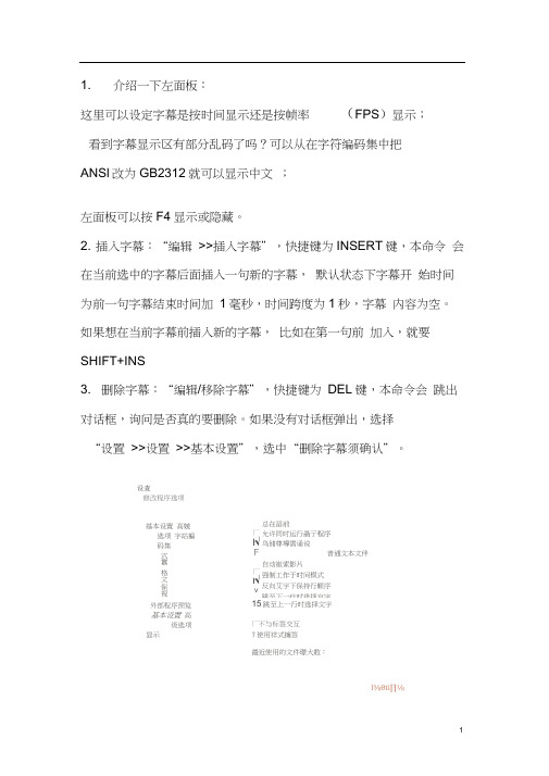
设査修改程序选项基本设置高皴选项字站褊码集式囂格文保视厂l√F厂ι√V总在畐前允许同时运行聶亍程序鸟储尊導需诵说普通文本文伴自动崔索影片强制工作于时间模式反向艾宇下保持行顺序跳至下一疔时选择宜字外部程序预览基本设置高级选项显示15跳至上一行时选择文宇厂不与标签交互7使用祥式擁签最近使用的文件璟大数:l⅜θti∏⅛MkJ .∣∣U^4. 时间微调:1. 可以在“时间控件”中直接输入字幕的起止时间或者跨度(需要按回车后更改才生效);2. 可以上下翻动输入框右边的调整按钮(按键盘上的上下箭头亦可);3. ALT + C设定字幕起始时间为影片当前时间,ALT+ V设定字幕结束时间为影片当前时间;4. 另一种插入字幕的方法:ALT+ Z设定影片当前时间为字幕开始时间,ALT+ X设定影片当前时间为字幕结束时间,与上面C点不同的就是这个方法可以同时插入新的字幕。
内容输入:在“字幕内容编辑区”输入的字幕内容可以立刻显示在“字幕显示区”和影视预览区。
时间轴的制作真是一件费时费力的事情,为了把一句字幕显示的精确,需要反复的校对。
颜色定义:在当前字幕行点按鼠标右键即可发现颜色标记的功能,可定义亦可取消,非常方便。
Table of Contents
Table of ContentsModule 1: Getting Started With Altium Designer1.1Introduction to Altium Designer.........................................................................................1-11.2The Altium Designer environment.....................................................................................1-21.3Document Editor Overview................................................................................................1-61.4Working with projects and documents............................................................................1-10Module 2: Help and DXP system menu2.1Using the Help system.......................................................................................................2-12.2Using the Altium website...................................................................................................2-32.3DXP System menu...........................................................................................................2-10Module 3: Schematic Editor Basics3.1Schematic Editor basics....................................................................................................3-13.2Schematic graphical objects..............................................................................................3-43.3Schematic electrical objects..............................................................................................3-9Module 4: Schematic Capture4.1Introduction to Schematic Capture....................................................................................4-14.2The Schematic Editor workspace......................................................................................4-24.3Libraries and components.................................................................................................4-94.4Placing and wiring............................................................................................................4-17Module 5: Multi-Sheet Design5.1Multi-Sheet Design.............................................................................................................5-1Module 6: Building the Project6.1Assigning designators........................................................................................................6-16.2Compiling and verifying the project...................................................................................6-5Module 7: Setting Up for Transfer to PCB and Importing Data7.1Setting Up for Transfer to PCB..........................................................................................7-1Module 8: PCB Editor Basics8.1PCB Editor Basics..............................................................................................................8-18.2PCB design objects............................................................................................................8-4Module 9: Setting up the PCB9.1Setting up the PCB.............................................................................................................9-19.2Creating a new PCB..........................................................................................................9-69.3Setting up the PCB layers................................................................................................9-10Module 10: Global Editing10.1Editing Multiple Text Objects...........................................................................................10-110.2The Data Editing System.................................................................................................10-4Module 11: PCB Design Flow, Transferring a Design and Navigation11.1PCB design process........................................................................................................11-111.2Transferring design information to the PCB......................................................................11-311.3Using the PCB Panel.......................................................................................................11-711.4Project Navigation and Cross Probing..........................................................................11-16Module 12: Design Rules12.1Design rules and design rule checking...........................................................................12-1Module 13: Classes and Rooms13.1Object classes..................................................................................................................13-113.2Rooms..............................................................................................................................13-3Module 14: Placement and Re-annotation14.1Component Placement tools...........................................................................................14-114.2Re-Annotation and back annotate...................................................................................14-3Module 15: Schematic Library Editor15.1Introduction to Library Editing..........................................................................................15-115.2Schematic Library Editor..................................................................................................15-2Module 16: PCB Library Editor16.1PCB Library Editor...........................................................................................................16-116.23D dimensional component detail.................................................................................16-14Module 17: Linking Models, Parameters, Library Package and Updates17.1Adding Model and Parameter Detail to a Component..................................................17-117.2Component Auditing........................................................................................................17-817.33D PCB Components....................................................................................................17-1417.4Library Package types...................................................................................................17-1817.5Library Reports...............................................................................................................17-20Module 18: Routing and Polygons18.1Routing.............................................................................................................................18-118.2Testpoint System...........................................................................................................18-1018.3Adding and removing teardrops....................................................................................18-1518.4Automatic routing...........................................................................................................18-1618.5Polygons and the Polygon Manager.............................................................................18-19Module 19: Output Generation and CAM File Editing19.1Bill of Materials.................................................................................................................19-119.2Output Generation............................................................................................................19-819.3CAM Editor.....................................................................................................................19-20Module 20: Interfacing to 3D Mechanical CAD20.1Interfacing to 3D Mechanical CAD..................................................................................20-1。
NOC创作平台使用手册

NOC创作平台使用教程深圳市恩欧希互联科技有限公司目录1.安装注册 (1)1.1安装 (1)1.2注册 (1)1.2.1注册账号 (1)1.2.2.打开“开始菜单”运行程序(如图1) (1)1.2.3 登录 (1)1.2.4 登录成功 (2)2.NOC创作平台使用说明 (3)2.1界面介绍 (3)2.1.1菜单加速条 (4)2.1.2工具箱 (5)2.1.3效果栏 (8)2.1.4属性窗 (8)2.1.5节目区 (9)2.2操作介绍 (9)2.2.1建立一个新节目 (9)2.2.2页的创建、编辑、运行和测试 (10)2.2.3对象的创建和编辑 (10)2.2.3.1几何对象类 (11)2.2.3.2媒体对象类 (14)2.2.3.3复合和粘接对象类 (15)2.2.4对象属性的设置 (16)2.2.4.1外观设置 (17)2.2.4.2动作设置 (17)2.2.4.3交互设置 (21)2.2.5对象的常见属性操作 (23)2.2.6如何实现动画功能 (23)2.2.7如何实现交互功能 (25)2.2.8如何打包节目 (27)2.2.9素材管理 (28)2.2.9.1通过节目区设置 (29)2.2.9.2通过菜单设置 (29)2.2.10鼠标右键和键盘快捷键的使用 (30)3.范例 (33)3.1时钟运动 (33)3.2小车运动 (35)3.3旋转风车 (36)4.常用技巧与疑难解答 (39)1.安装注册1.1安装NOC创作平台的运行环境如下。
硬件:PentiumIII 1G以上,256M以上内存,200M以上硬盘剩余空间,4M 以上显存,VGA 卡,声卡,音箱。
推荐使用Pentium IV 2G以上,512M内存,16M显卡,1024x768显示模式。
软件:中文Windows XP/Windows 2003/Windows Vista/Windows 7环境。
安装步骤:按照安装提示做即可。
1.2注册1.2.1注册账号(1)登录网站。
Autodesk Inventor Content Center自定义:流程与优化说明书
Customizing the Inventor Content Center Customizing the Inventor Content CenterBarrett Kamille – IMAGINiT TechnologiesMA201-1L The Autodesk Inventor Content Center ships with over 700,000 parts. This session will show CAD managers and every-day users alike how to streamline their libraries to include only the parts they use. You’ll learn how this process accelerates not only a design team’s part-selection process, but also significantly increases the performance of the Content Center itself. In addition, attendees will learn how to publish their own custom parts to the Content Center and to modify and add default properties to standard library components such as internal part numbers and descriptions used in bills of materials and parts lists. About the Speaker:Barrett Kamille has over 12 years of experience in the Autodesk community focusing primarily on mechanical CAD and PDM products. He was part of the Autodesk Inventor product team for five years and was a consultant for Inventor, Vault and Productstream. Barrett brings a wealth of experience in the realm of CAD data management as well as database-driven applications. Barrett is currently a Senior Applications Engineer with IMAGINIiT; one of Autodesk’s largest business partners.OverviewThe Autodesk Inventor Content Center gives you the ability to access 700,000 unique, standard parts for use in your Inventor assemblies. This session will show you how to streamline your parts libraries to limit the availability as-per your company standard. You’ll learn how this process accelerates not only a design team’s part-selection process, but also significantly increases the performance of the Content Center itself. In addition, you will learn how to publish your own custom parts to the Content Center and to modify and add default properties to standard library components such as your own part numbers and descriptions for use in bills of materials and parts lists.After this lab you will be able to:•Create your own custom Content Center Library•Populate your library with standard components•Customize those standard components with company specific properties. (Ex. Company Part Numbers, Alternate Descriptions etc.)•Add your own company specific parts to your custom library•Perform backup and recovery of your custom librariesPrerequisitesThis class assumes a good working knowledge of Inventor, its environments and general functionality. Specifically you should be familiar with the user interface components and how to use Content Center to navigate and place parts within an assembly. The class will be conducted using Autodesk Inventor 2008 (similar methods apply in Autodesk Inventor 11).For More InformationFor more information on this or any other topic please visit:/mfgcommunitySetupTo prepare for this exercise ensure that you have both Autodesk Inventor 2008 an ADMS Console 2008 installed on your system:1) Launch ADMS Console 2008 and ensure that you have Autodesk Inventor 2008 ContentCenter libraries installed:NOTE: If you already have a library called “AI2008_MyLibrary”, delete it by right-clicking on it and choosing delete.2) Launch Inventor 2008 and make sure that you can connect to the Place from ContentCenter dialog:You are now ready to begin customizing your content center.Creating a Custom LibraryThe first step is to create your own custom library which will allow you to copy parts from the existing read-only Content Center libraries and will also allow you to modify the properties of these parts such as the description and part number.1) Start by opening ADMS Console 2008 – right click on Libraries and select CreateLibrary…:2) In the Display Name box type in “MyLibrary”. Keep the selection for Autodesk Inventor2008 in the Partition section and use the default of AI2008_MyLibrary as the database name:Click OK when finished. You will be notified that the library was successfully created. Note that the library has a different icon than the others indicating that it is read/write enabled.Adding the Custom Library to the current projectNow that you have a custom library you need to activate it within the current Inventor project.1) Open Inventor 2008 and select the Projects… button:2) Select the Configure Content Center Libraries button in the lower-right side of theProjects dialog:3) Click on the Add Library… button:4) Choose MyLibrary from the pulldown:Click OK to close this dialog.5) Your Configure Libraries dialog should now contain your custom library:Click OK to continue.Modifying the Custom LibraryNow you have created a custom library and have added it to the current Inventor project. From this point you can modify your custom library to include your company’s standard parts and apply your own descriptions and part numbers too them.1) Open Inventor 2008 and launch the Content Center Editor:(You may have to wait while the content center data is loaded from SQL Server)2) From the list of items on the left, right click on Fasteners->Rivets->Plain->Copy To->MyLibrary:(You will get a warning that this will take a few minutes to copy – allow it to copy)BREAK (while copying)3) When notified that that you need to refresh the local view choose Yes:4) In the Content Center Editor dialog change your view to MyLibrary:5) Now you can begin editing the parts you have copied. You can modify the properties:6) Change the Name to and the Description of the part:Choose OK to close the dialog – you will be asked to refresh your local view again.7) Change the File Naming scheme for the part you are editing (right click):8) :Add MyPart- as a prefix for new parts:Choose OK to continue.9) Modify the Family Table for the part so that you can edit its part number. Notice that thefilenames are already pre-pended with the MyPart- prefix. If you wanted you couldmodify part file names directly from here. Modify the part number for the first row:10) Delete a few rows of parts by clicking on the row number and holding the Ctrl or Shiftkeys and click Delete Row:Click OK when finished.11) Select a few of the other part families and right-click on one and choose Delete Family:You will be prompted to delete selected families, choose Yes.12) Once you have copied over and cleaned up your custom library using the standard content as a base, you can detach the standard content libraries from your system. Go to ADMS Console and expand the Libraries folder, right-click on a library and choose Detach. You can also delete the library but this is not recommended as you may need items from the library at a later time. Detaching it simply removes its link to the system without deleting the library file:13) Now you will add the modified part to an assembly. Start a new assembly, choose Place from Content Center and navigate to your custom part family:Choose the default sizes and pick OK to continue.14) Note the prefix for the new part name:Click Save to continue.15) Add a few instances of the part to the new assembly and open its Bill of Materials:16) Examine the new part number and description modified previously:Summary: You have created and customized a library using content center data. You have also removed unneeded part instances and families and have detached the no-longer needed Standard Content Center libraries. You now have complete control over which parts are used in an assembly as well as the part numbering and file naming conventions used.Adding custom parts to a Custom LibraryNow that you have created and copied data from a standard content library, you will see how you can add your own company’s parts to this library.1) Start by creating a part that will be used to simulate your company’s standard parts (oropen Bracket.ipt). Once finished go to Tools->Publish Part:2) In the Publish Guide dialog make sure that MyLibrary is selected and then click Next:Choose Next to Continue.3) In the Select Category to publish to pulldown, choose whatever is most appropriate foryour shape. If you are not sure which to use Choose Features->English->Block:Choose Next to continue.4) Unless you have chosen something other than Block, you can simply choose Next onthe Map Family Columns to Category Parameters dialog.5) For Define Family Key Columns, you are going to want to have both the Material andPart Number fields referenced in your family table. Choose the items so that theyappear in this order (you may need to use the arrow up and down keys on the right side of the dialog):6) You will now be prompted to add standard information for the new part:7) Select a thumbnail image for the new part – the default is to use Inventor’s thumbnail:Click Publish to place the part in the content library.8) Open a new assembly and navigate to the newly published part inside of the ContentCenter dialog:9) Place it into an assembly and check its bill of materials:Summary: you have now created a new library part and published it to your custom library which is now accessible using the Place From Content Center dialog. You can modify the properties of this new part using the methods described earlier.Backing up and Restoring Custom LibrariesAs a rule of thumb it is always a good idea to back up your custom libraries, especially once you have imported all of your parts and have made necessary changes.1) Open ADMS Console and log in as Administrator (no password). Go to Tools->Backupand Restore. Make sure Backup is selected and pick Next>.2) Make sure that Full Backup is selected and that Backup Standard Content is alsoselected. In the Backup Path field type in C:\ and select Finish:3) The backup will take a few minutes to complete.BREAK (while backup completes)4) When the backup is complete, go to your C:\ Drive. You should notice a new backup setwith today’s date and time as part of the folder name. Navigate inside this folder to see that your custom library (C:\VaultBackupXXXX\databases\AI2008_MyLibrary_dbak)exists. Once you have backed up the Standard Content Center Libraries you do notneed to do so again as they do not change (read-only).Summary: You have successfully backed up your content center and custom libraries. Restoring them is a reverse of the same process you just completed. If you have time, try restoring and using the libraries you just backed up.Customizing the Inventor Content Center20 Quiz Yourself1) What must be done first before you can create your own library of parts?a. Create a new Inventor Project fileb. Create a new custom library using ADMS Consolec. Create a new folder for the library partsd. Change the read only setting on a standard Content Center library2) How can you duplicate data from a standard Content Center library to a custom library?a. Edit the excel file that controls content centerb. Changing the read only setting on standard Content Center librariesc. Use the Copy To command to copy standard content to a read/write libraryd. There is no way to copy data from the standard content libraries3) How do you add your own parts to a custom library?a. The Content Center Editorb. The Publish… tool in Inventorc. Edit the Excel spreadsheet to add the new part informationd. ADMS Console4) Where are Content Center libraries modified (Part Numbers, etc.)?a. ADMS Consoleb. On a shared network drivec. On a dedicated content center serverd. Content Center Editor5) Where are Content Center libraries managed by the system?a. ADMS Consoleb. On a shared network drivec. On a dedicated content center serverd. Content Center EditorAnswers: 1b, 2c, 3b, 4d, 5a。
MCNP绘图常用的几个命令
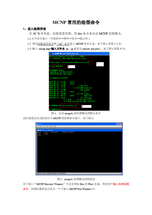
MCNP常用的绘图命令1、进入绘图界面在4C版本里面,如果需要绘图,用dos命令来启动MCNP绘图模式。
1.1打开命令窗口(开始程序→附件→命令→提示符);1.2 利用切换盘符命令和“cd”命令进入MCNP所在目录,如下图1的第1-2步;1.3 输入mcnp inp=输入文件名ip(ip意思为initiate and plot),如下图1的第3步;图1、启动mcnp4c的绘图模式的默认命令此时系统会自动给你打开MCNP的绘图命令窗口,如下图2:图2、mcnp4c绘图模式初始状态在子窗口“MCNP Execute Window”中会有类似Dos的Plot>出现,等待用户输入各种绘图命令,绘图结果将显示在另一个子窗口MCNP Plot Window中。
2、基本绘图命令介绍2.1常见绘图命令图3、mcnp常见绘图命令列表2.2 绘图命令解释1)Options:显示可用命令的关键词列表;2)Status:显示绘图参数的当前值;3)Exit:退出查询命令菜单。
4)Basis X1 Y1 Z1 X2 Y2 Z3:第一个X1 Y1 Z1向量是屏幕水平方向,第二个X2 Y2 Z3向量是屏幕的垂直方向。
格式:basis 1 0 0 0 1 0 ;屏幕显示的是X-Y平面5)Origin:视平面的中心。
格式:origin X Y Z ;表示模型的坐标原点6)Extent EH EV:限制视平面的大小。
例1:对于PX截面,origin X Y Z extent Y1 Z1;则屏幕显示区域为水平方向Y-Y1、Y+Y1;Z-Z1、Z+Z1例2:extent 数字1 或者是extent 数字1 数字2,分别大小为数字1*数字1或是数字1*数字2的区域7)PX,PY,PZ:各方向上的截面,以PX例,相当于basis 0 1 0 0 0 1 origin VX vy vz。
例:PX 1.0 basis 0 1 0 0 0 1 origin 1.0 vy vz8)Label S C DES:S、C分别指是否在曲线、区上打印标号,DES指示区标的意义。
Earthworks 艾尔斯维克 ICON USB 流媒体麦克风使用说明书
I C O NSTUDIO-QUALIT YUSB STRE AMING MICROPHONEFor more information, please visit or call 1-603-654-2433.1 ICON USB Microphone with Custom Triad-Orbit Stand 1 USB CableYOUR PURCHASE INCLUDESThank you for purchasing theEarthworks ICON USB Streaming Microphone!The ICON is class-compliant, so users don't need to install a driver on any OS in order to use itBegin by removing all included components from the packaging. Make sure to mute any incoming signal to speakers or headphones to avoid any loud “pops” when connecting. Connect the microphone to your given device with a USB port. Confirm in your computer's settings that ICON is recognized as an audio device (appearing as "USB Audio CODEC").When using your ICON, be sure to take advantage of its features, such as:• Gain Knob: This can be found on the back of the microphone, as shown above. The center position is the default setting, and is best for speech at a medium-loud volume from 3 inches away. The knob can be adjusted depending on your distance from the microphone. Turning it right increases the gain, and turning it left lowers the gain. (When turning, you will also feel a click when the knob is at the center position. Use this as an indicator of its position when you're not looking at the back.)• If the ICON is set as your computer’s output device, the computer’s master output volume will control the ICON’s output level. If it isn’t set as the output device, you can adjust it in your computer’s control panel. If you’re using a smart device like an iPhone or iPad, you can control the ICON’s volume using the device’s master volume control.• Haptic Analog Mute Switch: This can be activated by pushing in on the gain knob on the back of the microphone. Think of this as the microphone's E-Brake; when engaged, no sound will pass through. We've included it as an additional safety level beyond the digital mute on your computer. When pressing the knob, you will also hear an audible click sound to indicate you've been muted. (The click sound will not occur when unmuting the microphone.)• LED Indicators: Found under the microphone, where the body meets the ball joint, the LED indicator will light up depending on these criteria:• Blue: the microphone is plugged in and powered on.• Green: the computer is actively streaming audio from the microphone.• Red: the analog circuitry in the microphone is clipping.• Low Handling Noise: We've paid special attention to making sure the ICON does not make noise when you move it. As such, feel free to touch/move/adjust the microphone while it is powered on - and know that you will experience very little noise while doing so.• Integrated M2-R Ball Adapter: The ICON can be unscrewed from its included Triad-Orbit stand and mounted on any microphone stand or boom mount.GE T TING S TAR TED US ING YOUR ICONS PECIFIC ATION S 37 Wilton Rd. Milford, NH 03055 (603) 654-2433************************ © 2021 Earthworks, Inc To guarantee your microphone provides years of performance, follow these guidelines:• Avoid extreme heat and condensing humidity. Allow the microphone to warm up when bringing it in from the cold.• Rough handling may damage the microphone even if no markings are visible.• When not in use, keep the microphone in its box.• Windows users intending to record audio using a Digital Audio Workstation (DAW) with ASIO driverswill want to install the free ASIO4ALL driver (). Doing so will guarantee the lowest-possible latency for real-time monitoring and playing software instruments.• If you wish to use the ICON with a smart device, be sure you have an adapter that can simultaneously connect the mic to the device while supplying external power. For example, we would recommend the Apple Lightning to USB 3 Camera Adapter.If you encounter issues while using your Earthworks Audio microphone, please make sure that:• Your USB cable is well connected on both ends.• Your microphone is confirmed as an input device on your computer.• The microphone is positioned at an appropriate distance from the sound source.• External noise in your recording environment is kept to a minimum.• Your recording space is at room temperature and free of dust.If your issue persists after checking, please contact us via our website.TROUBLE S HOOTING PROPER MAINTENANCE ADVANCED US E WARR ANT Y The ICON and ICON Pro carry a two-year limited warranty (parts and labor). Please register your warranty at:/register. If you have any problems with your Earthworks products, please contact our warranty/repairdepartmentbyemailat:***************************.NOTE: This warranty only applies to Earthworks microphones purchased brand new. For microphones purchased/received second-hand, please contact us via our website.WE 'RE HE RETO HELP For anything else, we're a phone call or email away. Please feel free to contact us by email at ************************,orbyphoneat(603)-654-2433.ICONFrequency Response20Hz-20kHz Polar PatternCardioid Peak Acoustic input132dB SPL ConnectionMicro USB to USB A Power SourceUSB Bus Power Power Consumption70 mA at 5V (Bus Power)Typical Headphoneimpedance16 Ohms Headphone Output Power50 mW (at 16 Ohms)ColorStainless Steel Dimensions5.53" x 1.6"Weight1.5lb。
blackmagic design 说明
blackmagic design 说明下载温馨提示:该文档是我店铺精心编制而成,希望大家下载以后,能够帮助大家解决实际的问题。
文档下载后可定制随意修改,请根据实际需要进行相应的调整和使用,谢谢!并且,本店铺为大家提供各种各样类型的实用资料,如教育随笔、日记赏析、句子摘抄、古诗大全、经典美文、话题作文、工作总结、词语解析、文案摘录、其他资料等等,如想了解不同资料格式和写法,敬请关注!Download tips: This document is carefully compiled by the editor. I hope that after you download them, they can help you solve practical problems. The document can be customized and modified after downloading, please adjust and use it according to actual needs, thank you!In addition, our shop provides you with various types of practical materials, suchas educational essays, diary appreciation, sentence excerpts, ancient poems, classic articles, topic composition, work summary, word parsing, copy excerpts, other materials and so on, want to know different data formats and writing methods, please pay attention!黑魔法设计(Blackmagic Design)是全球领先的数字影视技术公司,其产品覆盖了摄像机、视频编辑软件、信号处理设备等各个领域。
操作手册实用PPT文档
垂直爐管
1
National Nano Device Laboratories
Create for the future 國家奈米元件實驗室垂直爐管操作手冊
1. 使用設備卡及密碼開啟系統。 2. 操作垂直爐管之前,必須登入MSC II。 登入:
(1)從功能選擇單,選擇[login]。 (2)在密碼區輸入密碼,選擇[OK]按鈕。 3. 批次執行 步驟1:點選螢幕下方之[PCS]按鈕
Create for the future 國家奈米元件實驗室垂直爐管操作手冊
步驟6:選擇須執行的條件後,點選[Queue]。
圖6 Batch Manager視窗 7
National Nano Device Laboratories
Create for the future 國家奈米元件實驗室垂直爐管操作手冊
圖1 在右方主螢幕顯示PCS功能
2
National Nano Device Laboratories
Create for the future 國家奈米元件實驗室垂直爐管操作手冊
步驟2:點選圖1右方之[Edit Operations]按鈕,出現下方畫面。 在此畫面設定recipe,溫度表格及設定片數等等。
圖7 Cassette Workbench
8
National Nano Device Laboratories
Create for the future 國家奈米元件實驗室垂直爐管操作手冊
步驟8:輸入Lot Identifier,按[OK]按鈕。
圖8 Batch 的指示將晶舟放進機台中,即可執行。
9
National Nano Device Laboratories
- 1、下载文档前请自行甄别文档内容的完整性,平台不提供额外的编辑、内容补充、找答案等附加服务。
- 2、"仅部分预览"的文档,不可在线预览部分如存在完整性等问题,可反馈申请退款(可完整预览的文档不适用该条件!)。
- 3、如文档侵犯您的权益,请联系客服反馈,我们会尽快为您处理(人工客服工作时间:9:00-18:30)。
ROM Policy Development
Spring 2000 – ROM board adopts governance model Redefined its fundamental role and responsibilities: specifically the care, protection and safeguarding of ROM collections, property, premises and resources Required board task force to develop and monitor policies to articulate Museum’s mandate, vision, values and objectives, limits of executive authority project co-ordinated through executive office of Museum’s Chief Operating Officer Fall 2001/Spring 2002 – 20 policies approved Cover everything from health and safety to repatriation of Canadian aboriginal objects
MCN/NINCH Copyright Workshop Sept. 7, 2002, Toronto, Canada.
Putting Together a Museum's IP Policy: Renaissance ROM as a Case Study
Brian Porter (brianp@rom.on.ca) Royal Ontario Museum
ROM Digital Desired Outcomes
Crafting a long term vehicle for disciplined capture and secure storage of digital assets Protecting the ROM’s assets Providing access to more of the collections for wider audiences Helping people to make personal connections Extending education beyond our boundaries Growing revenues to sustain the program Improving our own efficiency
1 million physical visitors 1.5 million web visitors
More than five million objects
BOARD ROM Foundation President/CEO
President & Executive Director
Vice-President Collections & Research
Copyright Policy Process
No clear guidelines/principles in the Museum community that could be easily adopted (professional associations, other museums). Task Force examined intellectual property/copyright issues/concerns applicable to ROM as producer/creator, publisher/distributor, and consumer: Collections - permanent & loan Exhibition right, Reproduction right etc. i.e. exhibiting designer dresses, publishing catalogues/books, etc. Original research by curators Collections-based research, field research (sponsorship issues) Works based on the collections by non-employees volunteers, Students, Curators Emeritus, External Scholars Photographs/Video/Digitization Publications
ROM’s Options
Managed retreat
Real operating budget has been declining for 12 years with little prospect for growth despite increased reliance on self-generated revenues.
ROM Copyright Policy
Need for IP policy based on:
Recognition that information is a vital institutional asset, central to the Museum’s role and purpose. Recognition that information is increasingly seen as commodity that can be purposefully used to further institutional interests. Demands for increased self-sufficiency, to build revenuegeneration. Importance of intellectual property in creating ROM programs, exhibits, products; need to comply with law in the use of diverse intellectual property interests (liability). – ie. ROM field guide series and use of images by curators Inconsistent past practice at the ROM; potential to negatively impact institutional interests.
Opening Points
I am not a lawyer or policy writer. “I know what I don’t know.” “I am Canadian.” So is Celine Dion. I have a confession. I like journalists. “What a great way to spend your life!” It is now 4 R’s: Rights to Reproduce Rina’s Reasons Bandwidth. Think three per cent. Have fun. Respect the time! Meet my friend.
ROM Digital
A comprehensive program to systematically digitize, store and manage our collections information and leverage digital assets
E.g. access, education, licensing
Education & Programs
Museum Sales Hosting & Special Services
NEW MEDIA RESOURCES •Information Centre & Library •Information Technology •Media Productions •Publications •Photography •Web
Chief Operating Officer
Director Collections Management Director Research
Vice-President Exhibits, Programs & New Media Resources Exhibit Planning and Community Programs Exhibit Design
Language of business: the ROM’s digital imperative is driven by business initiatives Initiatives require:
New New New New Technology Policy Process Organization
ROM Policy Development
Policies complement ROM Digital initiative:
Public Access – access to collections and information resources a key responsibility Copyright – prudent and fair use of its resources and protection in real world Information Management – information as a corporate and organizational asset, includes practice statement on use of IT resources Publications – promotes core ROM activities
