UG3002-T中文资料
立鼎光电探测器产品手册(第二版)说明书
光电探测器产品手册(第二版)立鼎光电@郭玉西Tel*************Mob:139****43722016年8月20日立鼎光电探测器事业部简介西安立鼎光电科技有限公司是一家专业从事各种光电类产品及其部件、组件、元件的研发生产、系统集成、专业代理销售推广为一体的高新技术企业。
公司专注于为客户提供从元件、组件、部件到全套光电系统产品的完整解决方案。
总部位于中国古都西安的电子城街区和高新技术开发区之间,周围有众多知名高校、科研院所及高新技术企业,科研创新氛围浓厚,是公司人才引进和技术创新的强大源泉。
为了高效便捷地服务于国内广大客户,公司在北京、深圳、上海、武汉、香港等地设有分公司或办事处。
公司自成立以来,秉承“资源整合,自主创新”之思想研发产品的同时,也致力于将国外的先进产品和技术引进到国内。
立鼎光电探测器事业部以市场为导向,有效整合探测器资源,多年来与世界多家知名的探测器厂商建立了紧密的合作关系,一直专注于探测器产品在国内的售前、售中及售后的优质服务。
客户范围覆盖了航空、航天、兵器、船舶、电子、核工业等十大军工集团以及中科院所、知名高校和工农业领域。
我们始终秉承“领先技术、诚实服务、合作共赢”的发展理念,真诚与国内外广大用户、合作伙伴及同行携手合作,共创光电事业美好明天!产品目录光电探测器中华立鼎(CLPT)短波点元/焦平面探测器--------------------------------------------4 波兰VIGO公司MCT探测器及组件-----------------------------------------------------10 美国InfraRed 中/长波及双色探测器-----------------------------------------------------13 德国IFW 紫外探测器-----------------------------------------------------------------------18 美国EOS全波段光电探测器---------------------------------------------------------------22 美国GPD近红外探测器--------------------------------------------------------------------25 西班牙NIT硒化铅中波探测器------------------------------------------------------------29 德国ALPHALAS可见光/近红外高速探测器-------------------------------------------36 美国AGI短波/中波探测器-----------------------------------------------------------------40美国Teledyne Judson全波段探测器------------------------------------------------------43 俄罗斯Ekran像增强器及光电倍增管----------------------------------------------------45一、中华立鼎(CLPT )公司短波探测器前瞻技术研究室中华立鼎光电是一家研发、生产高品质InGaAs 短波探测器的公司,其产品从点元探测器到面阵探测器一应俱全,质量可靠,价格合理,得到世界客户的广泛认可和应用。
SGM3002中文资料
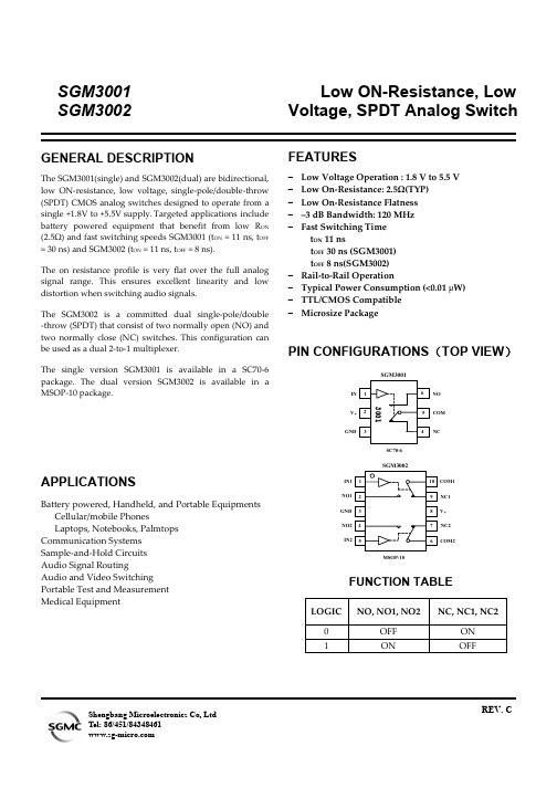
PIN DESCRIPTION
NAME
SC70-6 PIN
V+
2
GND
3
IN(IN1, IN2)
1
COM(COM1, COM2)
5
NO(NO1, NO2)
6
NC(NC1, NC2)
4
MSOP-10 PIN
8 3
1,5
6,10 2,4 7,9
FUNCTION
Power supply Ground Digital control pin to connect the COM terminal to the NO or NC terminals Common terminal Normally-open terminal Normally-closed terminal
Stresses beyond those listed under “Absolute Maximum Ratings” may cause permanent damage to the device. These are stress ratings only, and functional operation of the device at these or any other conditions beyond those indicated in the operational sections of the specifications is not implied. Exposure to absolute maximum rating conditions for extended periods may affect device reliability. (1) Signals on NC, NO, or COM or IN exceeding V+ will be clamped by internal diodes. Limit forward diode current to maximum current ratings.
ADVANTEST U3741 U3751 U3771 U3772 说明书
MANUAL NUMBER C Printed in JapanADVANTEST CORPORATIONAll rights reserved .U3700 SeriesUser’s GuideFOE-8440185H00First printing November 20, 2004Applicable ModelsU3741U3751U3771U37722004Certificate of ConformityThis is to certify, thatcomplies with the provisions of the EMC Directive 89/336/EEC (All of these factors arerevised by 91/263/EEC,92/31/EEC,93/68/EEC) in accordance with EN61326and Low V oltage Directive 73/23/EEC (All of these factors are revised by 93/68/EEC)in accordance with EN61010.ADVANTEST Corp.ROHDE&SCHWARZ Tokyo, Japan Europe GmbHMunich, Germanyinstrument, type, designation3700.05Spectrum AnalyzerU3700 SeriesNo. CR B00CR-1有毒有害物质含量信息说明书•本有毒有害含量含量说明内容是为了贯彻[电子信息产品污染控制管理办法]而编制的。
This document is made for Chinese Administration on the Control of Pollution Caused by Electronic In-formation Products, unofficially called "China-RoHS".この文書は、中国の「電子情報製品汚染防止管理弁法」のための文書です。
C3-U3002产品需求说明书

目录第一章概述 (1)1.1主要功能和特点 (1)1.2产品选型 (1)1.3注意事项 (2)1.4技术规格 (3)第二章安装与接线 (7)2.1电源输入端子定义 (7)2.2开关量输入端子 (7)2.3开关量输出端子 (8)2.4传感器端子定义 (9)第三章操作方法 (10)3.1开机与空闲状态 (10)3.2置零 (10)3.3去皮 (10)3.4运行状态 (10)3.5暂停状态(L2.D=0或L2.D=3) (10)3.6停止运行 (10)3.7显示值的选择 (11)3.8手动加料 (11)3.9手动卸料/手动清管 (11)3.10手动夹/松袋 (11)3.11手动推袋 (11)3.12快捷编辑 (12)3.13菜单编辑一般操作 (13)第四章菜单详细说明 (15)4.1生产参数L1 (15)4.2控制参数L2 (16)4.4衡器参数L3 (18)4.5衡器校准L4 (19)4.6仪表参数L5 (21)第五章典型自动运行控制流程(应用篇) (22)5.1准备 (22)5.2有计量斗自动定量控制 (22)5.3无计量斗自动定量控制 (24)5.4灌装自动定量控制 (25)5.5暂停及暂停中的操作 (26)第六章常见故障处理 (27)6.1操作错误提示 (27)6.2称重传感器故障检测方法 (27)6.3称重传感器故障排查 (28)第一章概述JY500C3系列定量控制器适于在各种有斗及无斗定量包装装置中作为控制部件。
JY500C3系列定量控制器为LED数码显示,带有十八个控制按键,操作简单,便于掌握。
主要用于建材、建筑行业中各种散装颗粒、分装物料和液体灌装的定量控制。
为了安全、正确地使用本仪表,充分发挥本仪表的作用,请您在使用本仪表之前务必详细阅读操作手册。
1.1主要功能和特点1)可预置目标值、提前量、落差与批数,并可快捷修改;2)可随时暂停当前自动运行控制,并转换为手动操作控制;3)快慢加料控制;4)具有自动避冲力延时功能;5)可随时暂停;6)具有按键去皮功能和自动去皮功能;7)可设置置零范围、判稳范围、滤波系数等参数;8)可进行无实物校准;更换传感器、仪表后均无须实物校准;9)全金属机箱,超强抗干扰能力,ESD达8000V,EFT达4000V;10)可选配带有模拟信号输出的产品;11)可选配带有数字通讯接口的产品;12)可选配带有日历时钟的产品;1.2产品选型产品型号为JY500C3□□□S:串口;C:串口+时钟;省略:无I:4——20mA;V:1——5V;省略:无A:基本型11.3注意事项1)开箱※开箱后,请妥善保管装箱单、合格证、说明书及附件配件。
武威市黄牛改良及肉牛生产情况的调研与思考
1 3 杂 交 技 术 .
户 和养 殖 小 区蓬勃 发 展 。黄牛 改 良是 牛 产 业 发展 的 前 提 和基 础 , 作为 一项 常 规实用 技 术 , 于 推进 养 牛 对
业 增 长方 式 的转 变 , 高 养牛效 益 和 质 量 , 提 推进 牛 产 业 化 发展 起 着重 要作 用 。
严秉 莲 , : 等 武威 市黄 牛改 良及 肉牛生产 情况 的调 研 与思考
3 9
育 肥场 5 9个 , 栏 肉 牛 2 9 9头 , 栏 肉 牛 64 0 3 2 综合效 益 不佳 存 5 出 8 . 头 ; 成养牛小区 7 建 5个 , 栏 肉 牛 1 3 存 51 1头 , 出栏 肉牛屠 宰加 工线 三条 , 设计 年加 工 屠宰 能力 90 0t 0 ,
乳兼 用 型品 种一 西 门达尔 牛冻 精 对本 地 黄 牛进 行 冻
精 配种 杂交 改 良 , 效 地 促 进 了黄 牛改 良工作 。九 有 十 年代 , 引进 夏 洛 来 、 木 辛 、 埃 蒙 特 、 格 斯 、 又 利 皮 安 德 国黄 牛等 优 良肉 牛冻 精 开展 了 肉 牛 三 元 杂 交 , 大 大 提高 了肉牛 生 产 效 益 。据 试 验 测 定 : 元 杂 交 犊 三
4 对 策 建 议
黄 牛冻 配改 良是 提 高 养 牛 生 产 水 平 最 成 熟 、 最 有 效 、 经 济 的技术 措 施 之 一 , 增 加 农 民收 入 、 最 对 提 升 牛产业 发 展水 平 具 有 重 要 意 义 , 一 项 长 期 持 久 是 的 系统工 程 [ 。武 威市 正在 大力 实 施 百万 头 肉牛 生 4 ]
THS3002资料
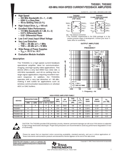
PRODUCTION DATA information is current as of publication date. Products conform to specifications per the terms of Texas Instruments standard warranty. Production processing does not necessarily include testing of all parameters.元器件交易网IMPORTANT NOTICETexas Instruments and its subsidiaries (TI) reserve the right to make changes to their products or to discontinueany product or service without notice, and advise customers to obtain the latest version of relevant informationto verify, before placing orders, that information being relied on is current and complete. All products are soldsubject to the terms and conditions of sale supplied at the time of order acknowledgement, including thosepertaining to warranty, patent infringement, and limitation of liability.TI warrants performance of its semiconductor products to the specifications applicable at the time of sale inaccordance with TI’s standard warranty. Testing and other quality control techniques are utilized to the extentTI deems necessary to support this warranty. Specific testing of all parameters of each device is not necessarilyperformed, except those mandated by government requirements.CERTAIN APPLICATIONS USING SEMICONDUCTOR PRODUCTS MAY INVOLVE POTENTIAL RISKS OFDEATH, PERSONAL INJURY, OR SEVERE PROPERTY OR ENVIRONMENTAL DAMAGE (“CRITICALAPPLICATIONS”). TI SEMICONDUCTOR PRODUCTS ARE NOT DESIGNED, AUTHORIZED, ORWARRANTED TO BE SUITABLE FOR USE IN LIFE-SUPPORT DEVICES OR SYSTEMS OR OTHERCRITICAL APPLICATIONS. INCLUSION OF TI PRODUCTS IN SUCH APPLICATIONS IS UNDERSTOOD TOBE FULLY AT THE CUSTOMER’S RISK.In order to minimize risks associated with the customer’s applications, adequate design and operatingsafeguards must be provided by the customer to minimize inherent or procedural hazards.TI assumes no liability for applications assistance or customer product design. TI does not warrant or representthat any license, either express or implied, is granted under any patent right, copyright, mask work right, or otherintellectual property right of TI covering or relating to any combination, machine, or process in which suchsemiconductor products or services might be or are used. TI’s publication of information regarding any thirdparty’s products or services does not constitute TI’s approval, warranty or endorsement thereof.Copyright © 1999, Texas Instruments Incorporated。
MAX3002EUP+T中文资料

General DescriptionThe MAX3000E/MAX3001E/MAX3002–MAX3012 8-channel level translators provide the level shifting nec-essary to allow data transfer in a multivoltage system.Externally applied voltages, V CC and V L , set the logic lev-els on either side of the device. Logic signals present on the V L side of the device appear as a higher voltage logic signal on the V CC side of the device, and vice-versa.The MAX3000E/MAX3001E/MAX3002/MAX3003 use an architecture specifically designed to be bidirectional without the use of a directional pin.The MAX3000E/MAX3001E/MAX3002/MAX3004–MAX3012feature an EN input that, when low, reduces the V CC and V L supply currents to < 2µA. The MAX3000E/MAX3001E also have ±15kV ESD protection on the I/O V CC side for greater protection in applications that route signals externally. The MAX3000E operates at a guaranteed data rate of 230kbps. The MAX3001E operates at a guaranteed data rate of 4Mbps. The MAX3002–MAX3012 operate at a guaranteed data rate of 20Mbps over the entire specified operating voltage range.The MAX3000E/MAX3001E/MAX3002–MAX3012 accept V L voltages from +1.2V to +5.5V and V CC voltages from +1.65V to +5.5V, making them ideal for data transfer between low-voltage ASICs/PLDs and higher voltage systems. The MAX3000E/MAX3001E/MAX3002–MAX3012 are available in 20-bump UCSP™, 20-pin TQFN (5mm x 5mm), and 20-pin TSSOP packages.ApplicationsCMOS Logic-Level Translation CellphonesSPI™ and MICROWIRE™ Level Translation Low-Voltage ASIC Level Translation Smart Card Readers Cellphone Cradles Portable POS SystemsPortable Communication Devices Low-Cost Serial Interfaces GPSTelecommunications EquipmentFeatureso Guaranteed Data Rate Options230kbps (MAX3000E)4Mbps (MAX3001E)20Mbps (MAX3002–MAX3012)o Bidirectional Level Translation Without Using a Directional Pin (MAX3000E/MAX3001E/MAX3002/MAX3003)o Unidirectional Level Translation (MAX3004–MAX3012)o Operation Down to +1.2V on V Lo ±15kV ESD Protection on I/O V CC Lines (MAX3000E/MAX3001E)o Ultra-Low 0.1µA Supply Current in Shutdown o Low Quiescent Current (< 10µA)o UCSP, TQFN, and TSSOP PackagesMAX3000E/MAX3001E/MAX3002–MAX3012+1.2V to +5.5V , ±15kV ESD-Protected, 0.1µA,35Mbps, 8-Channel Level Translators________________________________________________________________Maxim Integrated Products1Ordering InformationTypical Operating Circuit19-2672; Rev 4; 12/06For pricing, delivery, and ordering information,please contact Maxim/Dallas Direct!at 1-888-629-4642, or visit Maxim’s website at .UCSP is a trademark of Maxim Integrated Products, Inc.SPI is a trademark of Motorola, Inc.MICROWIRE is a trademark of National Semiconductor.Ordering Information continued at end of data sheet.Pin Configurations and Functional Diagrams appear at end of data sheet.Note:All devices operate over the -40°C to +85°C operating temperature range.M A X 3000E /M A X 3001E /M A X 3002–M A X 3012+1.2V to +5.5V , ±15kV ESD-Protected, 0.1µA,35Mbps, 8-Channel Level Translators 2_______________________________________________________________________________________ABSOLUTE MAXIMUM RATINGSStresses beyond those listed under “Absolute Maximum Ratings” may cause permanent damage to the device. These are stress ratings only, and functional operation of the device at these or any other conditions beyond those indicated in the operational sections of the specifications is not implied. Exposure to absolute maximum rating conditions for extended periods may affect device reliability.(All voltages referenced to GND.)V CC ...........................................................................-0.3V to +6V V L...........................................................................................-0.3V to +6V I/O V CC_......................................................-0.3V to (V CC + 0.3V)I/O V L_...........................................................-0.3V to (V L + 0.3V)EN, EN A/B...............................................................-0.3V to +6V Short-Circuit Duration I/O V L_, I/O V CC_to GND .......Continuous Continuous Power Dissipation (T A = +70°C)20-Pin TSSOP (derate 7.0mW/°C above +70°C).........559mW 20-Bump UCSP (derate 10mW/°C above +70°C).......800mW 20-Pin 5mm x 5mm TQFN(derate 20.0mW/°C above +70°C)......................................1667mWOperating Temperature RangesMAX3001EAUP..............................................-40°C to +125°C MAX300_EE_P.................................................-40°C to +85°C MAX30_ _E_P ..................................................-40°C to +85°C Junction Temperature......................................................+150°C Storage Temperature Range.............................-65°C to +150°C Lead Temperature (soldering, 10s).................................+300°CELECTRICAL CHARACTERISTICSMAX3000E/MAX3001E/MAX3002–MAX3012+1.2V to +5.5V , ±15kV ESD-Protected, 0.1µA,35Mbps, 8-Channel Level Translators_______________________________________________________________________________________3ELECTRICAL CHARACTERISTICS (continued)(V CC = +1.65V to +5.5V, V L = +1.2V to V CC , EN = V L (MAX3000E/MAX3001E/MAX3002/MAX3004–MAX3012), EN A/B = V L or 0(MAX3003), T= T to T . Typical values are at V = +1.65V, V = +1.2V, and T = +25°C.) (Notes 1, 2)M A X 3000E /M A X 3001E /M A X 3002–M A X 3012+1.2V to +5.5V , ±15kV ESD-Protected, 0.1µA,35Mbps, 8-Channel Level Translators 4_______________________________________________________________________________________TIMING CHARACTERISTICSNote 2:For normal operation, ensure that V L < V CC . During power-up, V L > V CC does not damage the device.MAX3000E/MAX3001E/MAX3002–MAX3012+1.2V to +5.5V , ±15kV ESD-Protected, 0.1µA,35Mbps, 8-Channel Level Translators_______________________________________________________________________________________5TIMING CHARACTERISTICS (continued)(V CC = +1.65V to +5.5V, V L = +1.2V to V CC , EN = V L (MAX3000E/MAX3001E/MAX3002/MAX3004–MAX3012), EN A/B = V L or 0(MAX3003), T= T to T . Typical values are at V = +1.65V, V = +1.2V, and T = +25°C.) (Notes 1, 2)M A X 3000E /M A X 3001E /M A X 3002–M A X 3012+1.2V to +5.5V , ±15kV ESD-Protected, 0.1µA,35Mbps, 8-Channel Level Translators 6_______________________________________________________________________________________TIMING CHARACTERISTICS —MAX3002–MAX3012(V CC = +1.65V to +5.5V, V L = +1.2V to V CC , EN = V L (MAX3002/MAX3004–MAX3012), EN A/B = V L or 0 (MAX3003), T A = T MIN to T) (Notes 1, 2)MAX3000E/MAX3001E/MAX3002–MAX3012+1.2V to +5.5V , ±15kV ESD-Protected, 0.1µA,35Mbps, 8-Channel Level Translators_______________________________________________________________________________________7Typical Operating Characteristics(T A = +25°C, unless otherwise noted.)2000150010005000-4010-15356085TEMPERATURE (°C)V L S U P P L Y C U R R E N T (µA )V L SUPPLY CURRENT vs. TEMPERATURE (DRIVING I/O V CC , V CC = 3.3V, V L = 1.8V)0200060004000800010,0001.52.53.02.03.54.04.55.05.5SUPPLY VOLTAGE (V)V C C S U P P L Y C U R R E N T (µA )V CC SUPPLY CURRENT vs. SUPPLY VOLTAGE(DRIVING I/O V L , V L = 1.8V)01002003004005006001.52.52.03.03.54.04.55.05.5V L SUPPLY CURRENT vs. SUPPLY VOLTAGE(DRIVING I/O V L , V L = 1.8V)SUPPLY VOLTAGE (V)V L S U P P L Y C U R R E N T (µA )05001500100020002500-4010-15356085TEMPERATURE (°C)V C C S U P P L Y C U R R E N T (µA )V CC SUPPLY CURRENT vs. TEMPERATURE (DRIVING I/O V CC , V CC = 3.3V, V L = 1.8V)020406080100104050203060708090100CAPACITIVE LOAD (pF)V L S U P P L Y C U R R E N T (µA )V L SUPPLY CURRENT vs. CAPACITIVE LOAD ON I/O V CC (DRIVING I/O V L , V CC = 3.3V, V L = 1.8V)02000100040003000600050007000103040205060708090100CAPACITIVE LOAD (pF)V C C S U P P L Y C U R R E N T (µA )V CC SUPPLY CURRENT vs. CAPACITIVE LOAD ON I/O V CC (DRIVING I/O V L , V CC = 3.3V, V L = 1.8V)CAPACITIVE LOAD (pF)R I S E /F A L L T I M E (n s )9080706050403020500100015002000010100MAX3000ERISE/FALL TIME vs. CAPACITIVE LOAD ON I/O V CC (DRIVING I/O V L , V CC = 3.3V, V L = 1.8V)M A X 3000E /M A X 3001E /M A X 3002–M A X 3012+1.2V to +5.5V , ±15kV ESD-Protected, 0.1µA,35Mbps, 8-Channel Level Translators 8_______________________________________________________________________________________Typical Operating Characteristics (continued)(T A = +25°C, unless otherwise noted.)0102030405060103020405060708090100CAPACITIVE LOAD (pF)R I S E /F A L L T I M E (n s )MAX3001ERISE/FALL TIME vs. CAPACITIVE LOAD ON I/O V CC (DRIVING I/O V L , V CC = 3.3V, V L = 1.8V)864201030204050CAPACITIVE LOAD (pF)R I S E /F A L L T I M E (n s )MAX3002–MAX3012RISE/FALL TIME vs. CAPACITIVE LOAD ON I/O V CC (DRIVING I/O V L , V CC = 3.3V, V L = 1.8V)050010001500200010206080100CAPACITIVE LOAD (pF)R I S E /F A L L T I M E (n s )MAX3000ERISE/FALL TIME vs. CAPACITIVE LOAD ON I/O V L (DRIVING I/O V CC , V CC = 3.3V, V L = 1.8V)30405070900102030405060103020405060708090100CAPACITIVE LOAD (pF)R I S E /F A L L T I M E (n s )MAX3001ERISE/FALL TIME vs. CAPACITIVE LOAD ON I/O V L (DRIVING I/O V CC , V CC = 3.3V, V L = 1.8V)43211020152530CAPACITIVE LOAD (pF)R I S E /F A L L T I M E (n s )MAX3002–MAX3012RISE/FALL TIME vs. CAPACITIVE LOAD ON I/O V L (DRIVING I/O V CC , V CC = 3.3V, V L = 1.8V)100200300400500104050203060708090100CAPACITIVE LOAD (pF)P R O P A G A T I O N D E L A Y (n s )MAX3000EPROPAGATION DELAY vs. CAPACITIVE LOAD ON I/O V CC (DRIVING I/O V L , V CC = 3.3V, V L = 1.8V)MAX3000E/MAX3001E/MAX3002–MAX3012+1.2V to +5.5V , ±15kV ESD-Protected, 0.1µA,35Mbps, 8-Channel Level Translators_______________________________________________________________________________________9Typical Operating Characteristics (continued)(T A = +25°C, unless otherwise noted.)100200300400500600103020405060708090100CAPACITIVE LOAD (pF)P R O P A G A T I O N D E L A Y (n s )MAX3000EPROPAGATION DELAY vs. CAPACITIVE LOAD ON I/O V L (DRIVING I/O V CC , V CC = 3.3V, V L = 1.8V)03961215CAPACITIVE LOAD (pF)P R O P A G A T I O N D E L A Y (n s )1030204050MAX3001EPROPAGATION DELAY vs. CAPACITIVE LOAD ON I/O V L (DRIVING I/O V CC , V CC = 3.3V, V L = 1.8V)013245CAPACITIVE LOAD (pF)P R O P A G A T I O N D E L A Y (n s)1020152530MAX3002–MAX3012PROPAGATION DELAY vs. CAPACITIVE LOAD ON I/O V L (DRIVING I/O V CC , V CC = 3.3V, V L = 1.8V)1µs/divMAX3000E RAIL-TO-RAIL DRIVING (DRIVING I/O V L , V CC = 3.3V, V L = 1.8V,CV CC = 50pF, DATA RATE = 230kbps)GNDI/O V L_1V/div GNDMAX3000E/01E/02-12 toc19I/O V CC_2V/div 40ns/divMAX3001E RAIL-TO-RAIL DRIVING (DRIVING I/O V L , V CC = 3.3V, V L = 1.8V,CV CC = 50pF, DATA RATE = 4Mbps)GNDI/O V L_1V/div GNDMAX3000E/01E/02-12 toc20I/O V CC_2V/div 10ns/divMAX3002–MAX3012 RAIL-TO-RAIL DRIVING (DRIVING I/O V L , V CC = 3.3V, V L = 1.8V,CV CC = 50pF, DATA RATE = 20Mbps)GNDI/O V L_1V/div GNDMAX3000E/01E/02-12 toc21I/O V CC_2V/div 0105201525301030204050CAPACITIVE LOAD (pF)P R O P A G A T I O N D E L A Y (n s )MAX3001EPROPAGATION DELAY vs. CAPACITIVE LOAD ON I/O V CC (DRIVING I/O V L , V CC = 3.3V, V L = 1.8V)428610121020152530CAPACITIVE LOAD (pF)P R O P A G A T I O N D E L A Y (n s )MAX3002–MAX3012PROPAGATION DELAY vs. CAPACITIVE LOAD ON I/O V CC (DRIVING I/O V L , V CC = 3.3V, V L = 1.8V)M A X 3000E /M A X 3001E /M A X 3002–M A X 3012+1.2V to +5.5V , ±15kV ESD-Protected, 0.1µA,35Mbps, 8-Channel Level Translators 10______________________________________________________________________________________Pin DescriptionMAX3000E/MAX3001E/MAX3002MAX3000E/MAX3001E/MAX3002–MAX301235Mbps, 8-Channel Level Translators Pin Description (continued)M A X 3000E /M A X 3001E /M A X 3002–M A X 301235Mbps, 8-Channel Level Translators Pin Description (continued)MAX3004–MAX3012______________________________________________Test Circuits/Timing DiagramsFigure 1a. Driving I/O V L Figure 1b. Timing for Driving I/O V LFigure 2a. Driving I/O V CC Figure 2b. Timing for Driving I/O V CCMAX3000E/MAX3001E/MAX3002–MAX301235Mbps, 8-Channel Level TranslatorsM A X 3000E /M A X 3001E /M A X 3002–M A X 301235Mbps, 8-Channel Level Translators _________________________________Test Circuits/Timing Diagrams (continued)Figure 3. Propagation Delay from I/O V L to I/O V CC After ENFigure 4. Propagation Delay from I/O V CC to I/O V L After ENsourced to each load on the V L side, yet the device does not latch up.The maximum data rate also depends heavily on the load capacitance (see the Typical O perating Characteristics), output impedance of the driver, and the operational voltage range (see the Timing Characteristics table).Input Driver Requirements The MAX3001E/MAX3002–MAX3012 architecture is based on a one-shot accelerator output stage. See Figure5. Accelerator output stages are always in three-state except when there is a transition on any of the translators on the input side, either I/O V L or I/O V CC. When there is such a transition, the accelerator stages become active, charging (discharging) the capacitances at the I/Os. Due to its bidirectional nature, both stages become active during the one-shot pulse. This can lead to some current feeding into the external source that is driving the translator. However, this behavior helps to speed up the transition on the driven side.F or proper full-speed operation, the output current of a device that drives the inputs of the MAX3000E/ MAX3001E/MAX3002–MAX3012 should meet the fol-lowing requirements:•MAX3000E (230kbps):i > 1mA, R drv< 1kΩ•MAX3001E (4Mbps):i > 107x V x (C + 10pF)•MAX3002–MAX3012 (20Mbps):i > 108x V x (C + 10pF)where i is the driver output current, V is the logic-supply voltage (i.e., V L or V CC) and C is the parasitic capaci-tance of the signal line.Enable Output Mode (EN, EN A/B) The MAX3000E/MAX3001E/MAX3002 and the MAX3004–MAX3012 feature an EN input, and the MAX3003 has an EN A/B input. Pull EN low to set the MAX3000E/ MAX3001E/MAX3002/MAX3004–MAX3012s’ I/O V CC1 through I/O V CC8 in three-state output mode, while I/O V L1 through I/O V L8 have internal 6kΩpulldown resis-tors. Drive EN to logic-high (V L) for normal operation. The MAX3003 is intended for bus multiplexing or bus switch-ing applications. Drive EN A/B low to place channels 1B through 4B in active mode, while channels 1A through 4A are in three-state mode. Drive EN A/B to logic-high (V L) to enable channels 1A through 4A, while channels 1B through 4B remain in three-state mode.±15kV ESD Protection As with all Maxim devices, ESD-protection structures are incorporated on all pins to protect against electro-static discharges encountered during handling and assembly. The I/O V CC lines have extra protection against static discharge. Maxim’s engineers have developed state-of-the-art structures to protect these pins against ESD of ±15kV without damage. The ESD structures withstand high ESD in all states: normal operation, three-state output mode, and powered down. After an ESD event, Maxim’s E versions keep working without latchup, whereas competing products can latch and must be powered down to remove latchup.MAX3000E/MAX3001E/MAX3002–MAX301235Mbps, 8-Channel Level Translators Detailed Description The MAX3000E/MAX3001E/MAX3002–MAX3012 logic-level translators provide the level shifting necessary to allow data transfer in a multivoltage system. Externally applied voltages, V CC and V L, set the logic levels on either side of the device. Logic signals present on the V L side of the device appear as a higher voltage logic signal on the V CC side of the device, and vice-versa.The MAX3000E/MAX3001E/MAX3002/MAX3003 are bidirectional level translators allowing data translation in either direction (V L↔V CC) on any single data line.These devices use an architecture specifically designed to be bidirectional without the use of a direc-tion pin. The MAX3004–MAX3012 unidirectional level translators level shift data in one direction (V L →V CC or V CC→V L) on any single data line. The MAX3000E/MAX3001E/ MAX3002–MAX3012 accept V L from +1.2V to +5.5V. All devices have V CC ranging from +1.65V to +5.5V, making them ideal for data trans-fer between low-voltage ASICs/PLDs and higher volt-age systems.The MAX3000E/MAX3001E/MAX3002/MAX3004–MAX3012 feature an output enable mode that reduces V CC supply current to less than 2µA, and V L supply current to less than 2µA when in shutdown. The MAX3000E/MAX3001E have ±15kV ESD protection on the V CC side for greater protection in applications that route signals externally. The MAX3000E operates at a guaranteed data rate of 230kbps; the MAX3001E oper-ates at a guaranteed data rate of 4Mbps and the MAX3002–MAX3012 are guaranteed with a data rate of20Mbps of operation over the entire specified operating voltage range.Level Translation For proper operation, ensure that +1.65V ≤V CC≤+5.5V,+1.2V ≤V L≤+5.5V, and V L≤V CC. During power-up sequencing, V L≥V CC does not damage the device.During power-supply sequencing, when V CC is floating and V L is powering up, up to 10mA current can beM A X 3000E /M A X 3001E /M A X 3002–M A X 301235Mbps, 8-Channel Level Translators ESD protection can be tested in various ways. The I/O V CC lines of the MAX3000E/MAX3001E are char-acterized for protection to ±15kV using the Human Body Model.ESD Test ConditionsESD performance depends on a variety of conditions.Contact Maxim for a reliability report that documents test setup, test methodology, and test results.Human Body ModelFigure 7a shows the Human Body Model and Figure 7b shows the current waveform it generates when dis-charged into a low impedance. This model consists of a 100pF capacitor charged to the ESD voltage of inter-est, which is then discharged into the test device through a 1.5k Ωresistor.Machine ModelThe Machine Model for ESD tests all pins using a 200pF storage capacitor and zero discharge resis-tance. Its objective is to emulate the stress caused by contact that occurs with handling and assembly during manufacturing. Of course, all pins require this protec-tion during manufacturing, not just inputs and outputs.Therefore, after PCB assembly, the Machine Model is less relevant to I/O ports.Figure 5. MAX3001E/MAX3002–MAX3012 Simplified Functional Diagram (1 I/O Line)Figure 6. Typical I IN vs. V INApplications InformationPower-Supply Decoupling To reduce ripple and the chance of transmitting incor-rect data, bypass V L and V CC to ground with a 0.1µF capacitor. To ensure full ±15kV ESD protection, bypass V CC to ground with a 1µF capacitor. Place all capaci-tors as close to the power-supply inputs as possible.I2C Level Translation For I2C level translation for I2C applications, please refer to the MAX3372E–MAX3379E/MAX3390E–MAX3393E datasheet.Unidirectional vs. Bidirectional LevelTranslator The MAX3000E/MAX3001E/MAX3002/MAX3003 bidi-rectional translators can operate as a unidirectionaldevice to translate signals without inversion. TheMAX3004–MAX3012 unidirecitional level translators,level-shift data in one direction (V L→V CC or V CC→V L) on any single data line (see the Ordering Information.)These devices provide the smallest solution (UCSPpackage) for unidirectional level translation withoutinversion. MAX3000E/MAX3001E/MAX3002–MAX301235Mbps, 8-Channel Level TranslatorsM A X 3000E /M A X 3001E /M A X 3002–M A X 301235Mbps, 8-Channel Level TranslatorsFigure 7a. Human Body ESD Test Model Figure 7b. Human Body Current WaveformSelector Guide**See Table 1.Table 1. Data RateMAX3000E/MAX3001E/MAX3002 Functional DiagramMAX3000E/MAX3001E/MAX3002–MAX301235Mbps, 8-Channel Level TranslatorsM A X 3000E /M A X 3001E /M A X 3002–M A X 301235Mbps, 8-Channel Level TranslatorsMAX3003 Functional DiagramMAX3000E/MAX3001E/MAX3002–MAX301235Mbps, 8-Channel Level TranslatorsPin ConfigurationsM A X 3000E /M A X 3001E /M A X 3002–M A X 301235Mbps, 8-Channel Level Translators 22______________________________________________________________________________________Pin Configurations (continued)MAX3000E/MAX3001E/MAX3002–MAX301235Mbps, 8-Channel Level Translators______________________________________________________________________________________23Pin Configurations (continued)Ordering Information (continued)*Future product—contact factory for availability.-T = Tape-and-reel package.Chip InformationTRANSISTOR COUNT: 1184PROCESS: BiCMOSM A X 3000E /M A X 3001E /M A X 3002–M A X 301235Mbps, 8-Channel Level Translators 24______________________________________________________________________________________Package Information(The package drawing(s) in this data sheet may not reflect the most current specifications. For the latest package outline information,go to /packages .)Package Information (continued)MAX3000E/MAX3001E/MAX3002–MAX301235Mbps, 8-Channel Level Translators (The package drawing(s) in this data sheet may not reflect the most current specifications. For the latest package outline information,go to /packages.)M A X 3000E /M A X 3001E /M A X 3002–M A X 301235Mbps, 8-Channel Level Translators Maxim cannot assume responsibility for use of any circuitry other than circuitry entirely embodied in a Maxim product. No circuit patent licenses are implied. Maxim reserves the right to change the circuitry and specifications without notice at any time.26____________________Maxim Integrated Products, 120 San Gabriel Drive, Sunnyvale, CA 94086 408-737-7600©2006 Maxim Integrated Productsis a registered trademark of Maxim Integrated Products.Package Information (continued)(The package drawing(s) in this data sheet may not reflect the most current specifications. For the latest package outline information,go to /packages .)Revision HistoryPages changed at Rev 4: 1, 2, 3, 10, 11, 15, 16, 21,23–26。
ug电子产品常用标准uh

电子产品常用标准信息技术类产品GB/T 9813-2000 微型计算机通用规范GB/T 18220-2000 手持式个人信息处理设备通用规范GB/T 18240-2000 电子收款机通用规范SJ/T 10360-1993 家用电子游戏机通用技术条件GB/T 17541-1998 学习机通用规范SJ/T 11193-1998 微型数字电子计算机多媒体性能规范GB/T 9313-1995 数字电子计算机用阴极射线管显示设备通用技术条件GB/T 9314-1995 串行击打式点阵打印机通用技术条件GB/T 17540-1998 台式激光打印机通用规范GB/T 17974-2000 台式喷墨打印机通用规范GB/T 14714-1993 微小型计算机系统设备用开关电源通用技术条件GB/T 14715-1993 信息技术设备用不间断电源通用技术条件GB/T 4967-1995 电子计算器通用技术条件GB/T 15279-1994 自动电话机技术条件YD/T 718-1994 录音电话机技术要求及测量方法GB/T 17113-1997 无绳电话机进网技术要求和测试方法GB/T 16891-1997 无绳电话系统设备总规范YD/T 696-1993 无绳电话机进网要求音视频类产品:GB/T 10239-1994 彩色电视广播接收机通用技术条件GB/T 9372-1988 电视广播接收机测量方法GB/T 17309.1-1998 电视广播接收机测量方法第一部份: 一般考虑射频和视频电性能测量以及显示性能的测量(IEC107-1:1995)SJ/T 11157-1997 电视广播接收机测量方法第二部份: 伴音通道的电性能测量一般测量方法和单声道测量方法GB/T 14859-1993 黑白电视广播接收机总技术条件GB/T 9382-1988 彩色电视广播接收机可靠性验证试验贝叶斯方法GB/T 14127-1993 黑白电视接收机可靠性验证试验贝叶斯方法GB/T 9379-1988 电视广播接收机主观试验评价方法SJ/T 10327-1992 电视广播接收机外观、结构和工艺评价方法SJ/T 9502-1991 彩色电视广播接收机质量分等标准SJ/T 9503-1992 黑白电视广播接收机质量分等标准GB/T 14960-1994 电视广播接收机用红外遥控发射器技术要求和测量方法SJ/T 10512-1994 电视广播接收机遥控部分的技术要求和测量方法GB/T 14858-1993 黑白监示器通用技术条件SJ/T 10603-1994 彩色监示器通用技术条件GB/T 2846-88 调幅广播收音机测量方法GB/T 6163-85 调频广播接收机测量方法GB/T 9374-88 声音广播接收机基本参数GB/T 2018-87 磁带录音机测量方法GB/T 2019-87 磁带录音机基本参数及技术要求GB/T14277-93 音频组合设备通用技术条件SJ/T 3258-89 普及级小型录音机总技术条件GB/T 9001-88 声频放大器测量方法SJ/T10406-93 声频功率放大器通用技术条件SJ/T10217-2000 家庭影院用环绕声放大器通用技术条件SJ/T10470-94 卡拉OK处理器通用技术条件GB/T15860-95 激光唱机通用技术条件SJ/T10730-1997 VCD视盘机通用技术条件SJ/T 超级VCD视盘机通用规范SJ/T DVD视盘机通用规范SJ/T10369-93 汽车收放机总技术条件SJ/T10447-93 汽车收、放、扩音机分类与基本参数SJ/T10448-93 汽车收、放、扩音机测量方法GB/T14185-93 语言学习系统通用技术条件GB/T 9003-88 调音台基本特性测量方法GB/T15640-1995 调音台通用技术条件GB/T12841-91 盒式磁带录音机运带机构总技术条件GB/T10197-88 盒式磁带录音机运带机构技术要求及测量方法SJ/T3252-89 普及级小型录音机运带机构总技术条件SJ/T10692-1996 汽车用盒式磁带放音机运带机构总技术条件SJ/T11128-1997 微盒式磁带录音机运带机构总技术条件GB/T15294-94 高保真调频广播调谐器最低性能要求(IEC581-2)GB/T14160-93 高保真唱盘最低性能要求(IEC581-3)GB/T14200-93 高保真声频放大器最低性能要求(IEC581-6)GB/T12062-89 高保真声频组合设备最低性能要求(IEC581-8)GB/T10372-93 车用高保真系统最低性能要求(IEC581-11)GB/T17310-1998 电视调谐接收器高保真声输出最低性能要求(IEC581-12)SJ/T10422-93 车用高保真调频广播调谐器最低性能要求(IEC581-13)SJ/T 9505-93 收录音机产品质量分等标准SJ/T 9566-95 音频组合设备质量分等标准SJ/T 9522-93 盒式磁带录音机运带机构质量分等标准通用电子测量仪器:SJ/T 2314-1983 直流数字电压表通用技术条件SJ/T 2811.1-1987 通用直流稳定电源术语及定义,性能与额定值SJ/T 2811.2-1987 通用直流稳定电源测试方法SJ/T 2943-1988 交流数字电压表通用技术条件SJ/T 2944-1988 交流数字电压表测试方法SJ/T 10541-1994 抗干扰交流稳压电源通用技术条件SJ/T 10542-1994 抗干扰交流稳压电源测试方法GB 17478-1998 低压直流电源设备的特性和安全要求(eqvIEC 1204:1993)GB/T 13978-1992 数字多用表通用技术条件GB/T 15151.1-1994 频率计数器通用技术条件GB/T 15151.1-1994 频率计数器测试方法通用电子元器件:GB/T 5729-1994 电子设备用固定电阻器第一部份:总规范GB/T 5730-1985 电子设备用固定电阻器第二部份:分规范低功率非线绕固定电阻器SJ/T 2789-1987 电子设备用电位器第五部份: 单圈旋转低功耗线绕和非线绕电位器SJ/T 2885-1988 电子设备用固定电感器总规范GB/T 2693-1990 电子设备用固定电容器第一部份:总规范GB/T 7332-1987 第二部份: 金属化聚脂膜介质直流固定电容GB/T 5993-1986 第四部份: 固体和非固体电解质铝电容器GB/T 5966-1986 第八部份: 1类瓷介固定电容器GB/T 5968-1986 第九部份: 2类瓷介固定电容器GB/T 6346-1986 第十部份: 金属箔式聚乙烯对笨二甲酸乙二醇酯膜介质直流固定电容器GB/T 11305-1989 电子设备用固定电容器: 3类瓷介固定电容器GB 3667-1997 交流电动机电容器GB/T 5095.1-1985 电子设备用机电元件基本试验规程及测量方法总则GB/T 8554-1998 电子和通信设备用变压器和电感器测量方法及试验程序GB 13028-1991 隔离变压器和安全隔离变压器技术要求GB/T 15290-1994 电子设备用电源变压器和滤波扼流圈总技术条件GB/T 9396-1996 扬声器主要性能测试方法(neq IEC 268-5:1989)GB/T 9397-1996 直接辐射式电动扬声器通用规范GB/T 7313-1987 高保真扬声器系统最低性能要求及测量方法(idtIEC 581-7)SJ/T 10218-2000 家庭影院用组合扬声器系统通用技术条件GB/T 15742-1995 汽车电喇叭性能要求及测量方法GB/T 16261-1996 印制板总规范GB/T 4588.1-1996 无金属化孔的单、双面印制板分规范GB/T 4588.2-1996 有金属化孔的单、双面印制板分规范GB/T 4588.4-1996 多层印制板分规范GB/T 10244-1988 电视广播接收机用印制板规范SJ/T 11171-1998 无金属化孔单双面碳膜印制板分规范SJ/T 2946-1988 彩色电视广播接收机用中频变压器及可调线圈SJ/T 2947-1988 彩色电视广播接收机用内附电容式中频变压器SJ/T 10139-1991 半导体调频广播接收机用中频变压器SJ/T 10290-1991 半导体调频广播接收机用内附电容式中频变压器SJ/T 10685-1995 半导体调幅广播接收机用中频变压器及振荡线圈GB/T 4023-1997 半导体分立器件第二部份:整流二极管GB/T 6351-1998 100A以下环境和管壳额定整流二极管空白详细规范SJ/T 10947-1996 电子元器件详细规范半导体绿色发光二极管SJ/T 10948-1996 电子元器件详细规范半导体红色发光二极管GB/T 12561-1990 发光二极管空白详细规范SJ/T 2558-1984 SM1~18型半导体发光数码管GB/T 15529-1995 半导体发光数码管空白详细规范GB/T 6217-1998 高低频放大环境额定双极型晶体管空白详细规范GB/T 7576-1998 高低频放大管壳额定双极型晶体管空白详细规范电器类产品:GB 7000.1-1996 灯具一般安全要求与试验(idt IEC 598-1:1992)GB 7000.2-1996 应急照明灯具安全要求(idt IEC 598-2-22:1990)GB 7000.4-1996 儿童感兴趣的可移式灯具安全要求(idt IEC 598-2-10:1987)GB 7000.6-1996 内装变压器的钨丝灯灯具安全要求(idt IEC 598-2-6:1994)GB 7000.7-1997 投光灯具安全要求(idt IEC 598-2-5:1979)GB 7000.9-1998 灯串安全要求(idt IEC 598-2-20:1996)GB 7000.10-1999 固定式通用灯具安全要求(idt IEC 60598-2-1:1997)GB 7000.11-1999 可移式通用灯具安全要求(idt IEC60598-2-4:1997)GB 7000.12-1999 嵌入式灯具安全要求(idt IEC60598-2-2:1997)GB 15143-1994 管形荧光灯用交流电子镇流器一般要求和安全要求(idtIEC928:1990) GB 2313-1993 管形荧光灯镇流器的一般要求和安全要求(idtIEC920:1990)环境和可靠性试验:GB/T 2423-1986 电工电子产品基本环境试验规程(IEC68)GB/T 2423.1-1989 电工电子产品基本环境试验规程低温试验方法GB/T 2423.2-1989 电工电子产品基本环境试验规程高温试验方法GB/T 2423.3-1993 电工电子产品基本环境试验规程恒定湿热试验方法GB/T 2423.4-1993 电工电子产品基本环境试验规程交变湿热试验方法GB/T 2423.5-1995 电工电子产品基本环境试验规程冲击GB/T 2423.6-1995 电工电子产品基本环境试验规程碰撞GB/T 2423.8-1995 电工电子产品基本环境试验规程自由跌落GB/T 2423.10-1995 电工电子产品基本环境试验规程振动(正弦)试验GB/T 2423.21-1995 电工电子产品基本环境试验规程低气压试验GB/T 2423.22-1995 电工电子产品基本环境试验规程温度变化试验GB/T 9384-1997 广播收音机、广播电视接收机、磁带录音机、声频功率放大器(扩音机)的环境要求和试验方法SJ/T 10325-1992 汽车收放机环境试验要求和方法GB/T 5080.6-1996 设备可靠性试验恒定失效率假设的有效性试验(idt IEC605-6:1989)GB/T 5080.7-1985 设备可靠性试验恒定失效率假设下的失效率与平均无故障时间的验证试验方案(idt IEC605-7:1978)GB/T 12165-1998 盒式磁带录音机可靠性要求和试验方法GB/T 12840-1991 盒式磁带录音机运带机构可靠性要求和试验方法GB/T 9382-1988 彩色电视广播接收机可靠性验证试验贝叶斯方法GB/T 14127-1993 黑白电视接收机可靠性验证试验贝叶斯方法电磁兼容检测的主要标准:GB 4343-1995 家用和类似用途电动、电热器具,电动工具以及类似电器无线电干扰特性测量方法和允许值(CISPR 14:1993)GB 9254-1998 信息技术设备的无线电骚扰限值和测量方法(idt:CISPR 22:1997)GB 13837-1997 声音和电视广播接收机及有关设备无线电干扰特性限值和测量方法(eqvIEC/CISPR 13:1996)GB 17625.1-1998 低压电气及电子设备发出的谐波电流限值(设备每相输入电流≤16A)(eqvIEC61000-3-2:1995)GB 17625.2-1999 电磁兼容限值对额定电流不大于16A的设备在低压供电系统中产生的电压波动和闪烁的限制(eqvIEC61000-3-3:1994)。
测试仪器培训教材

测试仪器(3250)培训3250是一种全自动变压器测试系统,可测试的项目有LX (电感)LK (漏电感)TURN (圈比)PH (相位)PS (脚位短路)DCR (直流电阻)ACR (交流电阻)BL (电感平衡)CX (电容)ZX (交流阻抗)等等的精密测试仪器。
可接上开尔文四端测试夹进行单组变压器测试,也可藉由3001A 扫描盒进行变压器扫描测试。
此仪器不可置于阳光直射,多灰尘,潮湿的环境内,仪器上不可放置重物,仪器两侧与后侧的通风孔要保持通顺,不可堵塞以免仪器内部温度升高造成测试精度下降与频繁死机。
开机之前注意检查电源线,各测试信号线是否连接好,注意不可连续开关机,以免造成仪器损坏。
不可将液体倒入仪器各扫描盒内,以免仪器开机时内部短路,烧毁仪器。
不可用尖锐物件在仪器表面、显示屏上刻划。
仪器开机后若发出异响、冒烟、发出烧焦气味等异常,必须立即切断电源并通知相关人员进行检修。
开机调测试档案:1.2. 按Meas Display 进入变压器测试画面。
按TRANSFORMER SCNNING TEST 进入变压器扫描测试画面。
3.4.56.7.按TRANSFORMER ID进入变压器编号画面。
按RECALL进入变压器档案列表画面。
按Enter 后,显示屏中央出现一个对话框,利用数字键输入所需档案的序号,按Enter。
按Yes 后进入变压器编号画面。
8.在变压器编号画面后按NEXTPAGE进入测试条件画面。
9.在变压器测试条件画面按MEASDISP进入测试画面。
打开加电流测试设置1.在变压器测试画面按此键打开加电流设置按键。
2.按BIAS ON 打开加电流按BIAS OFF 关闭加电流3.确认测试架是否正确安置到扫描盒上,测试档案是否正确,将材料正确放入测试架内,踩下脚踏板开关,仪器即开始测试。
不良品如何判定:1.断线如下所示PIN LX TURN DCR1-2 -26354 uH 1。
00T 365214KΩ1-3 -15121 uH 20。
SDL-3002电能质量说明书

3 .............................................................................................................................. 标指术技要主�4 2 .............................................................................................................................. 能功要主置装�3 1 .............................................................................................................................. 点特术技置装�2 1 . . . . . . . . . . . . . . . . . . . . . . . . . . . . . . . . . . . . . . . . . . . . . . . . . . . . . . . . . . . . . . . . . . . . . . . . . . . . . . . . . . . . . . . . . . . . . . . . . . . . . . . . . . . . . . . . . . . . . . . . . . . . . . . . . . . . . . . . . . . . . 述 概 �1
司 公 限 有 术 技 力 电 大 山 东 山
册手户用
置装测监线在量质能电
2003-LDS
版 ]9002V[
ROHM KD3002-DC72A 说明书
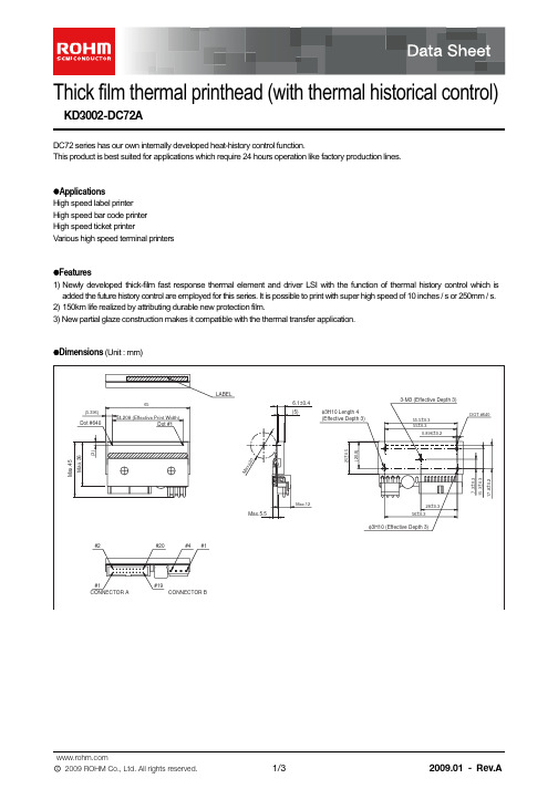
Thick film thermal printhead (with thermal historical control)KD3002-DC72ADC72 series has our own internally developed heat-history control function.This product is best suited for applications which require 24 hours operation like factory production lines.z ApplicationsHigh speed label printer High speed bar code printer High speed ticket printerVarious high speed terminal printersz Features1) Newly developed thick-film fast response thermal element and driver LSI with the function of thermal history control which is added the future history control are employed for this series. It is possible to print with super high speed of 10 inches / s or 250mm / s. 2) 150km life realized by attributing durable new protection film.3) New partial glaze construction makes it compatible with the thermal transfer application.z Dimensions (Unit : mm)z Equivalent circuitDI No.DI640 to 1DOT No.640 to 257256 to 1/ STB No./ STB2/ STB1DOT No.V HV DDGND/ RESETCLK DODI/ LOAD / STB2/ STB1STARTINCTM TMSEL2SEL1CONNECTORz Pin assignments/ RESET START DO NC TM TM / STB2/ STB1NC NCV H (COM)V H (COM)GND GND11121314151617181920No.CircuitNo.1234Circuit V DD V DD SEL2SEL1CLK (CP)NC DI NC INC / LOADNo.12345678910CircuitCONNECTOR A CONNECTOR Bz CharacteristicsParameter−Rave V H P O 54.2080.08476401250240.550.416408φ20.0−−SLT −−mm mm dots ΩV W/dot ms dots MHz mm −150/(1×108)5 to 45−−km/pulses°CEffective printing width Symbol Typical Unit Average resistance value Dot pitch Total dot number Maximum number of dots energized simultaneously Maximum clock frequency Maximum roller diameter Running life / pulse life Operating temperatureApplied power Applied voltage Print cyclez Data sheetsENERGY (mJ/dot)Fig.2 Representative density curveO P T I C A L D E N S I T YSCANNING LINE TIME (ms)Fig.3 Maximum energy curveS U P P L Y E N E R G Y (M a x .) (m J /d o t )Appendix-Rev4.0Thank you for your accessing to ROHM product informations.More detail product informations and catalogs are available, please contact your nearest sales office.ROHM Customer Support SystemTHE AMERICAS / EUROPE / ASIA / JAPANContact us : webmaster@rohm.co.jpAppendixNotesNo copying or reproduction of this document, in part or in whole, is permitted without the consent of ROHM CO.,LTD.The content specified herein is subject to change for improvement without notice.The content specified herein is for the purpose of introducing ROHM's products (hereinafter "Products"). If you wish to use any such Product, please be sure to refer to the specifications, which can be obtained from ROHM upon request.Examples of application circuits, circuit constants and any other information contained herein illustrate the standard usage and operations of the Products. The peripheral conditions must be taken into account when designing circuits for mass production.Great care was taken in ensuring the accuracy of the information specified in this document. However, should you incur any damage arising from any inaccuracy or misprint of such information, ROHM shall bear no re-sponsibility for such damage.The technical information specified herein is intended only to show the typical functions of and examples of application circuits for the Products. ROHM does not grant you, explicitly or implicitly, any license to use or exercise intellectual property or other rights held by ROHM and other parties. ROHM shall bear no re-sponsibility whatsoever for any dispute arising from the use of such technical information.The Products specified in this document are intended to be used with general-use electronic equipment or devices (such as audio visual equipment, office-automation equipment, communication devices, elec-tronic appliances and amusement devices).The Products are not designed to be radiation tolerant.While ROHM always makes efforts to enhance the quality and reliability of its Products, a Product may fail or malfunction for a variety of reasons.Please be sure to implement in your equipment using the Products safety measures to guard against the possibility of physical injury, fire or any other damage caused in the event of the failure of any Product, such as derating, redundancy, fire control and fail-safe designs. ROHM shall bear no responsibility whatsoever for your use of any Product outside of the prescribed scope or not in accordance with the instruction manual.The Products are not designed or manufactured to be used with any equipment, device or system which requires an extremely high level of reliability the failure or malfunction of which may result in a direct threat to human life or create a risk of human injury (such as a medical instrument, transportation equipment, aerospace machinery, nuclear-reactor controller, fuel-controller or other safety device). ROHM shall bear no responsibility in any way for use of any of the Products for the above special purposes. If a Product is intend-ed to be used for any such special purpose, please contact a ROHM sales representative before purchasing.If you intend to export or ship overseas any Product or technology specified herein that may be controlled under the Foreign Exchange and the Foreign Trade Law, you will be required to obtain a license or permit under the Law.。
海天注塑机资料汇总.ppt

意义 离太阳最近,技术最炙手可热 第二颗行星,美丽的名称和外表,技术锐不可挡 第四颗行星,特有的火红色象征着海天炙热的技术 太阳系行星中体积最大 体积第二,拥有极多卫星,可用于基础平台 有黑白两面,寓意天作之合 运行速度最快,海天高速机系列,预留 预留 第九行星,体积虽小但质量大 希腊众神之一,通过此机型将竞争对手打败
.精品课件.
19
机筒
• 氮化机筒 (38CrMoAl) • 双金属机筒 (40Cr+离心浇铸)
.精品课件.
20
02合模部分
1.自锁作用 2.增力作用
.精品课件.
21
移动模板滑脚
.精品课件.
22
移动模板滑脚
.精品课件.
23
自动润滑系统
定阻式
润滑点
润滑点
定量加压式
润滑点 润滑点
其它分配器
其它分配器
35
四、海天注塑机液压部分
.精品课件.
36
• 液压系统故障绝大多数是因为液压油引起的。液压元件中, 油泵对液压油的性能最为敏感,因泵内零件的运动速度最高, 工作压力也最高,且承压时间长,温升高。 • 液压油的最佳工作油温应在45℃左右,最高不能超过55℃。 油温太高,液压油粘度降低且易氧化变色产生油泥。 • 液压元件都是靠间隙密封,所以油质必须干净。 • 液压油油量要充足,不足易吸进气泡,产生气蚀。
海天注塑机客户培训
.精品课件.
1
提纲
• 海天注塑机型号简介 • 海天注塑机机械部分 • 海天注塑机电气部分 • 海天注塑机液压部分 • 海天注塑机伺服节能系列
.精品课件.
2
一、海天注塑机型号简介
.精品课件.
3
海天注塑机新命名
GPT-3002N型全站仪操作规程
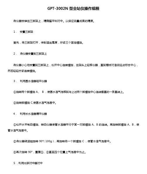
将仪器安装在三脚架上,精确整平和对中。
以保证测量成果的精度。
1.安置三脚架
首先,将三脚架打开,伸到适当高度,拧紧三个固定螺旋。
2.将仪器安置到三脚架上
将仪器小心地安置到三脚架上,松开中心连接螺旋,在架头上轻移仪器,直到锤球对准测站点标志中心,然后轻轻拧紧连接螺旋。
3.利用圆水准器粗平仪器
①旋转两个脚螺旋 A、 B ,使圆水准气泡移到与上述两个脚螺旋中心连线垂直的一条直线上。
②旋转脚螺旋 C,使圆水准气泡居中。
4.利用长水准器精平仪器
①松开水平制动螺旋、转动仪器使管水准器平行于某一对脚螺旋 A、B 的连线。
再旋转脚螺旋 A、B,使管水准气泡居中。
②将仪器绕竖轴旋转90°( 100g ),再旋转另一个脚螺旋 C ,使管水准气泡居中。
③再次旋转90°,重复①、②直至四个位置上气泡居中为止。
5 .利用光学对中器对中
根据观测者的视力调节光学对中器望远镜的目镜。
松开中心连接螺丝,轻移仪器,将光学对中器的中心标志对准测站点,然后拧紧连接螺旋。
在轻移仪器时不要让仪器在架头上有转动,以尽可能减少气泡的偏移。
6 .最后精平仪器
按第 4 步精确整平仪器,直到仪器旋转到任何位置时,管水准气泡始终居中为止,然后拧紧连接螺旋。
7.确认仪器已经整平后,打开电源开关,用软件设置开始工作。
PR-3002-EVA- 蒸发量变送器说明书
蒸发量变送器(模拟量型)Ver2.0目录第1章产品简介 (3)1.1产品概述 (3)1.2功能特点 (3)1.3主要参数 (4)1.4产品选型 (5)第2章硬件连接 (5)2.1传感器接线 (5)2.2设备安装调试 (5)第3章计算方法 (6)3.1电流型输出信号转换计算 (7)3.2电压型输出信号转换计算 (7)第4章免责声明 (7)第1章产品简介1.1产品概述PR-3002-EVA-*蒸发量变送器是我司研发的一款用来观测水面蒸发的仪器,产品采用双层不锈钢结构设计,可以防止太阳直晒导致的蒸发量误差,测量精度更加准确,且产品整机采用304不锈钢材质制作,外观精美,耐腐蚀,可有效保证传感器的使用寿命。
使用数字化传感器,拥有测量精度高,宽量程,高灵敏,无温度漂移、时漂、性能长期稳定等特点。
采用标准工业接口4~20mA/0~10V/0~5V模拟量信号输出,可接入现场数显表、PLC、变频器、工控主机等设备。
设备采用压力测量式原理,通过称重原理测量蒸发皿内液体的重量变化,然后算出液面高度,从而获得得到蒸发量,测量更精准,数据更科学;不受液体结冰的影响,克服了使用超声波原理测量液面高度时出现的结冰时测量不准、无水时易损坏传感器、测量精度低等弊端。
产品适用于气象观测、植物栽培、种子培养、农林业、地质勘测、科学研究等领域。
既可与自动加水装置、数据采集发送装置等配套使用,实现蒸发过程自动监控,也可与数据采集存储装置(记录仪)组合使用,实现蒸发数据的自动存储,还可与雨量传感器、数据采集发送装置等搭配使用,实现蒸发、降雨过程的自动观测和远程传输。
此外,可以作为雨量站、蒸发站、气象站、环境监测站等设备的组成部分,用来观测气象或环境参数之一的“水面蒸发”。
1.2功能特点●整机选用304不锈钢材质制成,耐腐蚀,不起锈,外观精美,保证传感器使用寿命;●应用压力式测量原理,通过高精度的称重原理测量蒸发皿内液体的重量变化,再计算出液面高度,从而测量得到蒸发量,测量更精准,数据更科学;●采用底部出线的接线方式,减少明线,避免线路故障,安装方便,操作简单;●双层防护的设计结构,该产品独特的双层不锈钢设计,可以有效隔离外界干扰,使测量结果更加精准;●适应能力强,在风浪和降雨气候条件下也能正常观测,不失准确度,抗电磁干扰,即使停电后再通电,输出数据依然正确;●本产品为数字化传感器,无温漂、时漂,性能长期稳定。
ug材料库ug10.0中英文对照

ABS——树脂ABS-GF——增强塑料Acetylene_C2H2_Gas——乙炔气态Acetylene_C2H2_Liquid——乙炔液态Acrylic——丙烯酸塑料Air——空气Air_Temp-dependent_Gas——(毒气)AISI_310_SS——北美标准310 不锈钢AISI_SS_304-Annealed——北美标准不锈钢304 退火AISI_Steel_1005——北美标准钢1005AISI_Steel_1008-HR——北美标准钢1008-美国?AISI_Steel_Maraging——北美标准钢马氏体Aluminum_2014——铝合金2014Aluminum_5086——铝镁合金Aluminum_6061——铝合金6061Aluminum_A356——铝合金A356Ammonia_Gas——氨气Ammonia_NH3_Liquid——液体氨Aniso_Sample——不均样本(类别属于Template指样本)(各向异性)Argon_Ar_Gas——氩气Bismuth_Liquid——铋液体Brass——黄铜Bronze——青铜Carbon_Dioxide_Gas——碳处理二氧化物气体Carbon_Dioxide_Liquid——碳处理二氧化物液体Copper_C10100——无氧铜Engine_Oil_Liquid——发动机用油Epoxy——环氧树脂Ethylene_Glycol_Liquid——乙烯乙二醇液体Freon_Liquid_R12——氟利昂R12Glycerin_Liquid——甘油Helium_Gas——氦气Hydrogen_Gas_H2——氢气Inconel_718-Aged——铬镍铁合金718 老标准Iron_40——40铁Iron_60——60铁Iron_Cast_G25——铸铁G25Iron_Cast_G40——铸铁G40Iron_Cast_G60——铸铁G60Iron_Malleable——可锻造铁Iron_Nodular——球状石墨铸铁Isobutane_(R600a)_Gas——异丁烷气体Isobutane_(R600a)_Liq——异丁烷液体Lead_Liquid——液态铅Magnesium_Cast——铸造镁Mercury_Liquid——水银Methane_CH4_Gas——甲烷气体Methanol_CH3(OH)——甲醇液体Nak(22-78)_LiquidNaK(45-55)_Liquid——Nitrogen_Gas_N2——氮气Nylon——尼龙Ortho_Sample——正色样本Ortho_Sample_Legacy——正色样本复数Ortho_Sample_W_Damping——正色样本W阻尼Oxygen_Gas_O2——氧气PbBi(45-55)_Liquid——液态PbBiPolycarbonate——聚碳酸酯Polycarbonate-GF——聚碳酸酯Polyethylene——聚乙烯Polypropylene——聚丙烯Polypropylene-GF——聚丙烯Polyurethene-Hard——聚丙烯硬Polyurethene-Soft——聚丙烯软Potassium_Liquid——液体钾Propane_C3H8_Gas——丙烷PVC——聚氯乙烯R134a_C2H2F4_Gas——四氟乙烷气态R134a_C2H2F4_Liquid——四氟乙烷液态S/Steel_PH15-5——一种不锈钢SMC——片状模塑料Sodium_Liquid——金属钠液态Steel-Rolled——镀金钢Steel——钢Sulfur_Dioxide_Liquid——二氧化硫液体Titanium-Annealed——退火钛Titanium_Alloy——钛合金Titanium_Ti-6Al-4V——某种钛合金Tungsten——金属钨Waspaloy——美国牌号的高温合金钢water——水Water_saturated_Liquid——饱和的水Water_vapour_Gas——水蒸汽Manten——蔓藤。
T3002快充充电器说明书
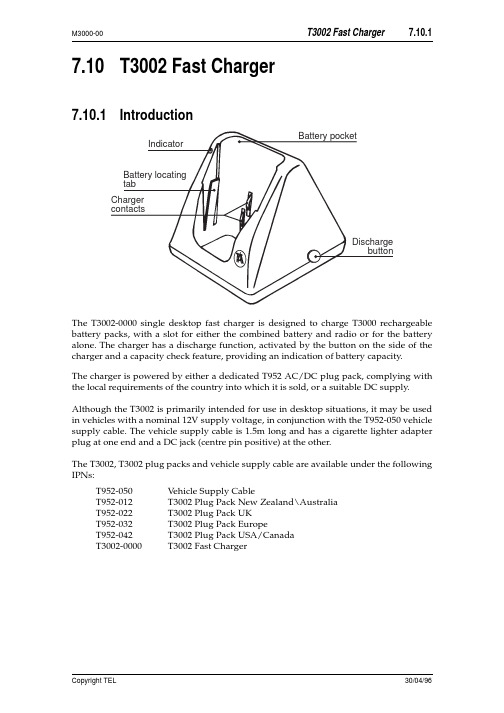
7.10T3002 Fast Charger7.10.1IntroductionThe T3002-0000 single desktop fast charger is designed to charge T3000 rechargeable battery packs, with a slot for either the combined battery and radio or for the battery alone. The charger has a discharge function, activated by the button on the side of the charger and a capacity check feature, providing an indication of battery capacity.The charger is powered by either a dedicated T952 AC/DC plug pack, complying with the local requirements of the country into which it is sold, or a suitable DC supply.Although the T3002 is primarily intended for use in desktop situations, it may be used in vehicles with a nominal 12V supply voltage, in conjunction with the T952-050 vehicle supply cable. The vehicle supply cable is 1.5m long and has a cigarette lighter adapter plug at one end and a DC jack (centre pin positive) at the other.The T3002, T3002 plug packs and vehicle supply cable are available under the following IPNs:T952-050V ehicle Supply CableT952-012T3002 Plug Pack New Zealand\AustraliaT952-022T3002 Plug Pack UKT952-032T3002 Plug Pack EuropeT952-042T3002 Plug Pack USA/CanadaT3002-0000T3002 Fast Charger7.10.2Performance SpecificationsPower Supply..10.8 to 16V DC, 13W maximumBattery Capacity..up to 2AHBattery Types..NiCd and NiMHOperating Temperature..+5°C to +40°C (best performance+15°C to +25°C)between Fast Charge Rate..800mADischarge Rate..400mATrickle Charge Rate:NiCd..115mANiMH..50mAStandby Charge Rate.. 2.2mACharge Duration:Fast (for an exhausted battery pack):NiCd.. 1.5 hours (typical)NiMH.. 2.5 hours (typical)Trickle:NiCd.. 1 hoursNiMH.. 2 hoursStandby..indefiniteEnd Of Charge Detection..- high voltage- ∆T (rate of temperature rise)- negative ∆V- high temperature cut-off- safety timer7.10.3WarningsAvoid extreme temperatures and direct sunlight when charging a T3000 batterypack. The required temperature range for the charger is 5°C to 40°C. Chargingefficiency is maximised around normal room temperature i.e. 15°C to 25°C.•T o give maximum battery life, do not recharge the battery until the ‘low battery warning’ is activated. This will avoid reduced battery capacity.7.10.4OperationPlace the charging unit on a stable horizontal surface and power the unit either from the T952 plug pack or the T952-050 vehicle supply cable.Check that the connectors are properly pushed home to ensure reliable electrical contact.Place the battery to be charged, with or without its radio, into the charging unit with the 4 contacts to the rear.•To locate a battery pack correctly in the charger, lean the top of the battery as far for-ward as possible to seat the bottom of the battery . Pivot the battery back against the contacts and it should snap into place.•After fast charging, the charge current terminates. The green LED then illuminates,indicating that trickle charge has commenced.•The battery may be left in the charger until needed, where it will be trickle orstandby charged, with no risk of damage.•The indicator beside the pocket indicates the charge status, as shown in the follow-ing table.7.10.4.1Discharge FunctionRegular discharging of the battery (at least weekly) will result in longer battery life.Note:The ‘discharge before charge’ feature can only be used on batteries with a date codenext to the serial number (e.g. G95). Earlier batteries cannot be discharged using a T3002.Press the discharge button to initiate a discharge-charge cycle.LEDConditionFunctionoffchargingsuspended•Incorrectly seated battery .•Charger powered but no battery present.•No power connected.amberwaitingBattery present, but awaiting charge while battery is being tested (3 seconds), or until the battery is within the correct temperature range for charging.green flashing discharging Battery is being being completely discharged.red fast charge Fast charge in progress.green standby charge Fast charge complete - trickle or standby charge in progress.red flashingfaultCharge suspended - faulty battery , or faulty charger.7.10.4.2Cycle & Capacity CheckIntroductionThe T3002 fast charger has a cycle and capacity check feature that discharges and charges a NiMH battery pack for 2 cycles, and a NiCd battery pack for 3 cycles. This means that the battery can be cycled and the capacity checked within a 16 hour period. The charger will then provide an indication of the batteries capacity.The cycle and capacity check function can also be used to rejuvenate batteries that have been stored without use for a significant time, or those suffering from reduced capacity through lack of regular exercise.When the T3002 is in the ‘cycle and capacity check’ mode, any discharge request by the user pressing the discharged button is ignored until the last charge cycle.Note:The capacity check feature can only be used on batteries with a date code next to the serial number (e.g. G95). Earlier batteries cannot be discharged using a T3002. ProcedureInsert the battery in the charger, while holding down the discharge button.Depress the discharge button until the indicator LED has changed from amber (battery being tested) to flashing green (battery discharging). The charger is now in ‘cycle and capacity check’ mode.Battery CapacityThe last battery discharge cycle is timed to give an approximate battery capacity. The indicator LED gives the charge and capacity status, as shown in the following table.LED Condition Functionamber waiting Battery present, but awaiting charge while battery is being tested (3 seconds), or until the battery is within the correct temperature range for charging.green flashing dischargingBattery is now discharging and is in ‘cycle and capacity check’mode.amber flashing low capacityBattery is less than 70% of the rated capacity, and will be leftdischarged.green capacity adequate Battery capacity is adequate. Fast charge is complete and trickle or standby charge is in progress.7.10.5Circuit DescriptionRefer to the T3002 block diagram, shown below.The DC supply to the charger feeds the 11.7V and 5V regulators, via a fuse.•The 11.7V regulator supplies the current source, LED, voltage interface and tempera-ture cutout circuitry.•The 5V regulator supplies the microprocessor and low voltage indicator (LVI) cir-cuitry.Battery voltage, temperature and capacity information is presented to the microproces-sor via the internal analogue to digital converter. V oltage information arrives through interface circuitry, that provides a normal battery voltage signal and an expanded volt-age signal (from 8.24V to 10.5V).This information, and any discharge request via the discharge button, is used by the microprocessor to appropriately switch on either the charging current source or the dis-charge circuitry.During charging, the current source is either continuously switched on (fast charge), or switched on and off at an appropriate duty cycle to provide trickle or standby charging. The exact state of the microprocessor is indicated to the user via the charger LED.The microprocessor can be put into a reset state if either of the following conditions occur:•The supply voltage drops and activates the LVI circuitry.•The internal charger temperature gets too hot and activates the temperature cut-out circuitry.T3002 Parts List (IPN 220-01342-01)Ref VAR IPN Description Ref VAR IPN Description!C1018-14100-00CAP 0603 CHIP 1N 50V X7R +-10%!C2018-16100-01CAP 0603 CHIP 100N +80-20% Y5V 16V!C3018-14100-00CAP 0603 CHIP 1N 50V X7R +-10%!C4018-14100-00CAP 0603 CHIP 1N 50V X7R +-10%!C5018-16100-01CAP 0603 CHIP 100N +80-20% Y5V 16V!C15018-16100-01CAP 0603 CHIP 100N +80-20% Y5V 16!C16018-16100-01CAP 0603 CHIP 100N +80-20% Y5V 16!C17018-16100-01CAP 0603 CHIP 100N +80-20% Y5V 16!C18018-16100-01CAP 0603 CHIP 100N +80-20% Y5V 16!C19018-14100-00CAP 0603 CHIP 1N 50V X7R +-10%!C20018-12330-00CAP 0603 CHIP 33P 50V NPO +-5%!C21018-12330-00CAP 0603 CHIP 33P 50V NPO +-5%!C22018-14100-00CAP 0603 CHIP 1N 50V X7R +-10%!C25018-15100-00CAP 0603 CHIP 10N 50V X7R +-10%!C30018-16100-01CAP 0603 CHIP 100N +80-20% Y5V 16!C40018-14100-00CAP 0603 CHIP 1N 50V X7R +-10%!C41018-12180-00CAP 0603 CHIP 18P 50V NPO +-5%!C42018-12180-00CAP 0603 CHIP 18P 50V NPO +-5%!C43018-16100-01CAP 0603 CHIP 100N +80-20% Y5V 16!C44018-12180-00CAP 0603 CHIP 18P 50V NPO +-5%!C45018-12180-00CAP 0603 CHIP 18P 50V NPO +-5%!C46018-14100-00CAP 0603 CHIP 1N 50V X7R +-10%!C47018-16100-01CAP 0603 CHIP 100N +80-20% Y5V 16!C48018-14100-00CAP 0603 CHIP 1N 50V X7R +-10%!C49016-08100-01CAP ELECT 6X4MM CHIP 10M 20% 16V !C50018-14100-00CAP 0603 CHIP 1N 50V X7R +-10%!C51018-16100-01CAP 0603 CHIP 100N +80-20% Y5V 16!C52018-16100-01CAP 0603 CHIP 100N +80-20% Y5V 16!C55018-16100-01CAP 0603 CHIP 100N +80-20% Y5V 16!C56018-14100-00CAP 0603 CHIP 1N 50V X7R +-10%!C57018-14100-00CAP 0603 CHIP 1N 50V X7R +-10%!C58018-12180-00CAP 0603 CHIP 18P 50V NPO +-5%!C60018-16100-01CAP 0603 CHIP 100N +80-20% Y5V 16!C61016-08100-01CAP ELECT 6X4MM CHIP 10M 20% 16V!D1001-00012-77(S) DIODE 1N6277A ZENER 18V 1500W!D3008-02099-00(S) LED RED/GREEN BI-COLOUR 3.1MM !D4001-10000-70(S) DIODE SMD BAV70 DUAL SWITCH SO !D6001-10000-70(S) DIODE SMD BAV70 DUAL SWITCH SO !D9001-10000-70(S) DIODE SMD BAV70 DUAL SWITCH SO !D12001-10014-03(S) DIODE SMD MBRS140T3 SCHOTTKEY!IC1002-00078-05(S) IC MC7805ACT 5V REG(LINEAR)1A!IC4002-06870-51(LS) IC MC68HC705P6P OTP MICRO 28!IC4A240-04020-95(L) SKT SMD DIP 28!IC5002-10340-64(S) IC SMD MC34064 LO VOLT SENSE!IC8002-10003-24(S) IC SMD 324 QUAD OP AMP SO14!Q1000-00295-50(S) XSTR MTP2955 FET TO-220!Q3000-10084-81(S) XSTR SMD BC848BW NPN SOT-323 S !Q4000-10084-81(S) XSTR SMD BC848BW NPN SOT-323 S !Q5000-10084-81(S) XSTR SMD BC848BW NPN SOT-323 S !Q6000-00295-50(S) XSTR MTP2955 FET TO-220!Q7000-10084-81(S) XSTR SMD BC848BW NPN SOT-323 S !Q8000-00012-49(S) XSTR TIP31 NPN PWR SWTCH TO220 !Q9000-10084-81(S) XSTR SMD BC848BW NPN SOT-323 S !Q10000-10084-81(S) XSTR SMD BC848BW NPN SOT-323!R2036-14470-10RES M/F 0805 CHIP 4K7 1%!R15038-14100-00RES 0603 CHIP 1K0 1/16W +-5%!R16036-15470-10RES M/F 0805 CHIP 47K 1%!R17036-13560-00RES M/F 0805 CHIP 560E 5%!R18036-15100-10RES M/F 0805 CHIP 10K 1%!R19038-17100-00RES 0603 CHIP 1M 1/16W +-5%!R20036-13820-00RES M/F 0805 CHIP 820E 5%!R21036-13560-00RES M/F 0805 CHIP 560E 5%!R22036-16120-10RES M/F 0805 CHIP 120K 1%!R23036-15100-10RES M/F 0805 CHIP 10K 1%!R24036-15470-10RES M/F 0805 CHIP 47K 1%!R25038-17100-00RES 0603 CHIP 1M 1/16W +-5%!R30036-16100-10RES M/F 0805 CHIP 100K 1%!R31036-15180-10RES M/F 0805 CHIP 18K 1%!R32036-11180-10RES M/F 0805 CHIP 1E8 1%!R33038-14470-00RES 0603 CHIP 4K7 1/16W +-5%!R34038-14100-00RES 0603 CHIP 1K0 1/16W +-5%!R35038-14470-00RES 0603 CHIP 4K7 1/16W +-5%!R36038-14100-00RES 0603 CHIP 1K0 1/16W +-5%!R37036-11180-10RES M/F 0805 CHIP 1E8 1%!R38036-11180-10RES M/F 0805 CHIP 1E8 1%!R39036-11180-10RES M/F 0805 CHIP 1E8 1%!R45038-14100-00RES 0603 CHIP 1K0 1/16W +-5%!R46036-15100-10RES M/F 0805 CHIP 10K 1%!R47036-15100-10RES M/F 0805 CHIP 10K 1%!R48036-15100-10RES M/F 0805 CHIP 10K 1%!R49036-15100-10RES M/F 0805 CHIP 10K 1%!R50036-15390-10RES M/F 0805 CHIP 39K 1%!R51038-14470-00RES 0603 CHIP 4K7 1/16W +-5%!R52036-15390-10RES M/F 0805 CHIP 39K 1%!R53036-15390-10RES M/F 0805 CHIP 39K 1%!R54036-15100-10RES M/F 0805 CHIP 10K 1%!R55036-15100-10RES M/F 0805 CHIP 10K 1%!R56036-16120-10RES M/F 0805 CHIP 120K 1%!R57038-14100-00RES 0603 CHIP 1K 1/16W +-5%!R58036-15330-00RES M/F 0805 CHIP 33K 5%!R59038-14100-00RES 0603 CHIP 1K0 1/16W +-5%!R60036-15100-10RES M/F 0805 CHIP 10K 1%!R61036-15100-10RES M/F 0805 CHIP 10K 1%!R62036-11180-10RES M/F 0805 CHIP 1E8 1%!R63036-11180-10RES M/F 0805 CHIP 1E8 1%!R64036-11180-10RES M/F 0805 CHIP 1E8 1%!R65036-11180-10RES M/F 0805 CHIP 1E8 1%!R66036-11180-10RES M/F 0805 CHIP 1E8 1%!R67036-11180-10RES M/F 0805 CHIP 1E8 1%!R68036-11180-10RES M/F 0805 CHIP 1E8 1%!R69036-11180-10RES M/F 0805 CHIP 1E8 1%!R70036-11180-10RES M/F 0805 CHIP 1E8 1%!R71036-15390-10RES M/F 0805 CHIP 39K 1%!R72036-15100-10RES M/F 0805 CHIP 10K 1%!R75036-15100-10RES M/F 0805 CHIP 10K 1%!R76036-15100-10RES M/F 0805 CHIP 10K 1%!R77036-15100-10RES M/F 0805 CHIP 10K 1%!R78045-15100-00RES NTC SMD 10K 5%!R79045-15100-00RES NTC SMD 10K 5%!R80036-14120-00RES M/F 0805 CHIP 1K2 5%!R81036-14120-00RES M/F 0805 CHIP 1K2 5%!R82036-15470-10RES M/F 0805 CHIP 47K 1%!R83036-15180-10RES M/F 0805 CHIP 18K 1%!R84036-13560-00RES M/F 0805 CHIP 560E 5%!R86038-14100-00RES 0603 CHIP 1K0 1/16W +-5%!R87036-13560-00RES M/F 0805 CHIP 560E 5%!R88036-15180-10RES M/F 0805 CHIP 18K 1%!R89036-15100-10RES M/F 0805 CHIP 10K 1%!R90036-15100-10RES M/F 0805 CHIP 10K 1%!R91038-14100-00RES 0603 CHIP 1K0 1/16W +-5%!R92036-15100-10RES M/F 0805 CHIP 10K 1%!R93036-10000-00RES M/F 0805 CHIP ZERO OHM!SW1232-00010-29(L) SWITCH TACT 3.85MM RED STEM HSK1240-02020-07SKT DC JACK 5.5MM HOLE 2.5MM PIN!XL1274-00010-33XTAL 4MHZ TE-35 HC49U C/W TEFLON 220-01342-01(L) PCB T3002 SINGLE FAST CHARGER302-40038-00BUTTON RED T3002 OPERATING303-20051-01COVER TOP A1M2800 T3003 TRICKLE CHA303-20052-01COVER BTM A1M2801 T3003 TRICKLE CH303-50027-00CONTACT A3M2818 T3000 BAT CHARGER308-13110-00HSINK PCB MTG FOR VERT MNT TO220 C/308-13117-00HSINK TO-220 HOR PCB MOUNTING349-00010-22SCREW NO 4X3/8 PAN POZI PLASTITE365-00100-09LABEL WHITE VINYL 15X11MM S/A365-01450-00LABEL BLNK 38*9MM TAMPERMARK VOID365-01498-00LABEL MODEL ID T3002-0000369-00010-11FOOT RUBBER BUMP-ON S/A410-01100-00PKG A3A723 T3003 TRICKLE CHARGER459-30023-00USER GUIDE T3002 FAST CHARGERDevicePCBCircuitT3002 Grid Reference Index (IPN 220-01342-01)DevicePCBCircuitDevicePCBCircuit32:E11-L222:D01-L312:D11-L442:E01-L1!C11:H11-B8!C21:F31-C7!C31:F31-C7!C41:F31-D7!C51:F31-E7!C151:B51-A4!C161:C41-C4!C171:B51-D5!C181:B51-E5!C191:C31-A3!C201:D41-B1!C211:D41-B1!C221:A11-D3!C301:F31-G5!C401:C41-F2!C411:E31-G2!C421:E31-G2!C431:D21-G1!C441:E31-H2!C451:E31-H1!C461:E21-H0!C471:E21-H0!C481:F21-J2!C491:E21-J2!C501:C31-L3!C511:D21-L1!C521:E31-M5!C551:F41-A5!C561:F41-A5!C571:F41-B5!C581:F31-C6!C601:B01-F7!C611:E01-H7!D11:F41-C8!D32:H51-D21-E2!D41:D31-K31-K3!D61:E41-D61-D6!D91:F41-B51-B5!D121:F11-H3FUSE 1:H11-B8!HS-STUD 1:B1!HS 1:F2!IC11:G31-D7!IC41:B31-C2!IC4A 1:B31-C1!IC51:B51-E5!IC81:E31-L51-G31-G11-H51-C5!LINK12:G41-K7!LINK22:G51-J6!Q11:B11-G8!Q31:G41-D3!Q41:G41-E3!Q51:C41-F2!Q61:F21-H2!Q71:F21-J5!Q81:F21-J5!Q91:B01-F7!Q101:C01-G7!R21:B11-F8!R151:B51-B4!R161:B51-D6!R171:C21-A3!R181:A11-C3!R191:D41-B1!R201:G41-D3!R211:G51-E3!R221:C31-E1!R231:A31-C2!R241:A21-C2!R251:D31-F3!R301:E41-F6!R311:E41-F5!R321:F31-J4!R331:F21-H5!R341:F31-H5!R351:F31-H5!R361:F31-J5!R371:F31-J4!R381:F31-J4!R391:F31-J4!R451:C41-F2!R461:C31-F1!R471:C31-E1!R481:D31-F3!R491:D31-F3!R501:E31-G3!R511:D31-G2!R521:D31-G2!R531:D21-G1!R541:D31-G3!R551:D31-G3!R561:E31-G1!R571:E31-H2!R581:D31-H1!R591:F21-H2!R601:F21-H1!R611:E21-H0!R621:D11-H3!R631:D11-H3!R641:D11-H3!R651:E11-H3!R661:E11-J3!R671:E11-J3!R681:E11-J3!R691:E11-J3!R701:F11-J3!R711:D21-K3!R721:D21-K2!R751:E41-A6!R761:F41-A6!R771:F41-A5!R781:B11-B7!R791:G11-B7!R801:F41-B6!R811:F41-B6!R821:F31-B5!R831:F41-C6!R841:B51-D6!R851:F11-J2!R861:B01-F7!R871:B01-F6!R881:C01-G7!R891:C01-G6!R901:C01-H6!R911:B01-F7!R921:C31-F1!R931:C31-F1!R951:H51-E2!R2012:H51-J7!R2022:G51-K7!R2032:G51-K7!R2042:G21-J7!R2052:G21-J7SK11:J11-B8!SW11:A01-D3’TP12:F41-H7TP22:F41-B6TP32:F41-B6TP52:E41-D6!XL11:D41-B1T3002 Fast Charger PCB (IPN 220-01342-01) - Top CopperT3002 Fast Charger PCB (IPN 220-01342-01) - Bottom CopperM3000-00T3002 Fast Charger 7.10.11Copyright TEL30/04/96M3000-00T3002 Fast Charger7.10.1230/04/96。
拓普康3002全站仪常用功能简介及方量计算资料

第一节仪器部件简介图1 拓普康3002以拓普康3002为例对全站仪各部件进行介绍。
光学对中器的作用为全站仪竖轴通过地面对中目标;仪器中心标志位仪器中心所在高度;定线点指示器用于引导持镜员走到仪器视准线方向;圆水准器和管水准器用于调整全站仪的水平度。
水平制动螺旋用于限制全站仪的水平转动,水平微动螺旋可使全站仪在水平方向微小转动;垂直制动螺旋用于限制全站仪的竖直转动,垂直微动螺旋可使全站仪在竖直方向微小转动;粗瞄准器用于大致瞄准目标。
第二节仪器对中及整平首先将三脚架架到地面对中目标的上方,根据全站仪架设位置的地形调整三脚三条腿的长度,使三脚架上端面大致水平。
将仪器安置到三脚架上,固定脚A的位置,移动脚B和脚C并通过光学对中器观察地面对中目标使仪器竖轴进过地面对中目标,如图2。
移动时对中人员站在三脚架BC一侧,控制脚B和脚C的左右位置使全站仪在脚A与地面对中目标连线上移动,控制脚B、脚C 与脚A之间的距离使全站仪移至地面对中目标。
图2 全站仪对中示意图通过圆水准仪和管水准仪使全站仪水平。
使用圆水准仪粗平全站仪时,旋转全站仪上的某两个脚螺旋A、B,使圆水准器气泡移到A、B两脚螺旋中心连线中垂线上;再旋转脚螺旋C使圆水准器气泡居中;气泡移动过程如图3。
图3 圆水准器对中示意图使用管水准器时,转动管水准器使管水准器平行于某一对脚螺旋A、B连线,再旋转角螺旋A、B,使管水准器起爆居中。
将仪器绕竖轴旋转90度,再旋转另一个脚螺旋C,使管水准器起爆居中。
再次旋转90度,重复上述步骤直至四个位置上气泡居中为止。
根据观测者的视力调节光学对中器望远镜的目镜。
松开中心连接螺丝,将光学对中器的中心标志对准对中目标。
最后利用管水准器对仪器进行精确整平。
第三节全站仪基本测量一、准备工作测量前将望远镜对准明亮天空,旋转目镜筒,调焦看清十字丝;利用粗瞄准器内的三角形标志的顶尖瞄准目标点,照准时眼睛与瞄准器之间应保留有一定距离。
利用望远镜调焦螺旋使目标成像清晰。
XC62HP3002DL资料

505XC62H ETR0312_001.doc◆CMOS Low Power Consumption◆Small Dropout : 0.18V @ 60mA0.58V @ 160mA ◆Maximum Output Current : 165mA (V OUT =3.0V)◆Highly Accurate : ±2% (±1%) ◆Output Voltage Range: 2.0V~6.0V◆Stand-by Supply Current : 0.1μA (V OUT=3.0V) ◆SOT-25/SOT-89-5/USP-6B Package■GENERAL DESCRIPTIONThe XC62H series are highly precise, low power consumption,positive voltage regulators, manufactured using CMOS and laser trimming technologies. The series consists of a high precision voltage reference, an error correction circuit, and anoutput driver with current limitation.By way of the CE function, with output turned off, the series enters standby. In the stand-by mode, power consumption is greatly reduced. SOT-25 (150mW), SOT-89-5 (500mW) and USP-6B (100mW)packages are available.In relation to the CE function, as well as the positive logic XC62HR series, a negative logic XC62HP series (custom) is also available. ■APPLICATIONS●Battery powered equipment ●Voltage supplies for cellular phones ●Cameras, Video recorders ●Palmtops■TYPICAL APPLICATION CIRCUIT■FEATURESMaximum Output Current: 165mA (within max. p ower dissipation, V OUT =3.0V)Output Voltage Range : 2.0V ~ 6.0V in 100mV increments (1.5V ~ 1.9V semi-custom) Highly Accurate : Set-up Voltage ±2% (±1% for semi-custom products)Low Power Consumption: 3.0μA (TYP.) (V OUT =3.0, Output enabled): 0.1μA (TYP .) (Output disabled) Output Voltage Temperature Characteristics : ±100ppm /℃ (TYP .) Line Regulation : 0.2% / V (TYP .)Ultra Small Packages : SOT-25 (150mW) mini-moldSOT-89-5 (500mW) mini-power moldUSP-6B (100mW)■TYPICAL PERFORMANCE CHARACTERISTICS506XC62H SeriesSERIES CEVOLTAGE OUTPUTH ONXC62HR L OFFH OFFXC62HPL ONDESIGNATORDESCRIPTION SYMBOL DESCRIPTIONR : Positive ① CE Pin Logic P : Negative (Custom)② ③ Output Voltage 20~60:e.g. V OUT 3.0V → ②=3, ③=0V OUT 5.0V → ②=5, ③=0④ Temperature Characteristics 0 : + 100ppm (TYP .) 1 : + 1% (semi-custom) ⑤Output Voltage Accuracy2 : + 2% M : SOT-23 P : SOT-89-5 ⑥ Package TypeD :USP-6B R : Embossed tape, standard feed ⑦Device OrientationL : Embossed tape, reverse feedPIN NUMBERSOT-25 SOT-89-5 USP-6B PIN NAME FUNCTION 142, 5(NC)No Connection2 2 1 VIN Supply Voltage Input3 3 6 CE Chip Enable4 1 4 VSSGround5 5 3 VOUT Regulated Output Voltage■PIN CONFIGURATION*The dissipation pad for the USP-6B package should be solder-plated in recommended mount pattern and metal masking so as to enhance mounting strength and heat release.If the pad needs to be connected to other pins, it should be connected to the V IN pin.■PIN ASSIGNMENT■PRODUCT CLASSIFICATION●Ordering InformationXC62H ①②③④⑤⑥⑦■FUNCTIONH = High level L = Low level507XC62HSeries■PACKAGING INFORMATION●SOT-89-5●SOT-25 ●USP-6B508XC62H SeriesMARK VOLTAGE (V)MARK VOLTAGE (V)0 0.x -0 0.x1 1.x -1 1.x2 2.x -2 2.x3 3.x -3 3.x4 4.x -4 4.x5 5.x -5 5.x6 6.x -6 6.x7 7.x -7 7.x8 8.x -8 8.x9 9.x -9 9.x MARKVOLTAGE (V)MARK VOLTAGE (V)0 x.0 -x.01 x.1 -1 x.12 x.2 -2 x.23 x.3 -3 x.34 x.4 -4 x.45 x.5 -5 x.56 x.6 -6 x.67 x.7 -7 x.78 x.8 -8 x.89 x.9 -9 x.9■ MARKING RULE●SOT-25, SOT-89-5①②③④12354SOT-25(TOP VIEW)① Represents integer of the output voltage② Represents decimal number of the output voltage③ Based on internal standards ④ Represents assembly lot number.0 to 9, A to Z repeated (G, I, J, O, Q, W excepted)■BLOCK DIAGRAM524④③②①123SOT-89-5(TOP VIEW)509XC62HSeriesPARAMETER SYMBOLRATINGSUNITSInput Voltage V IN 12.0 V Output Current I OUT 500 mA Output Voltage V OUT V SS -0.3 ~ V IN +1.3 V CE Input VoltageV CEV SS -0.3 ~ V IN +1.3VSOT-25 150 SOT-89-5 500 Power DissipationUSP-6BPd 100mW Operating Temperature Range Topr-30 ~ +80 ℃ Storage Temperature RangeTstg-40 ~ +25℃===■ABSOLUTE MAXIMUM RATINGSTa=25℃■ELECTRICAL CHARACTERISTICSNOTE:*1: V OUT(T)=Specified output voltage .*2: V OUT(E)=Effective output voltage (i.e. the output voltage when "V OUT(T)+1.0V" is provided at the V IN pin while maintaining a certain I OUT value). *3: Vdif= {V IN1 (*5)-V OUT1 (*4)}*4: V OUT1= A voltage equal to 98% of the output voltage whenever an amply stabilized I OUT {V OUT(T)+1.0V} is input. *5: V IN1= The input voltage when V OUT1 appears as input voltage is gradually decreased.OUT(T)=(*1)XC62H Series■ELECTRICAL CHARACTERISTICS(Continued)OUT(T)=(*1)XC62HR4002 V OUT(T)=4.0V (*1)NOTE:*1: V OUT(T)=Specified output voltage .*2: V OUT(E)=Effective output voltage (i.e. the output voltage when "V OUT(T)+1.0V" is provided at the V IN pin while maintaining a certain I OUT value).*3: Vdif= {V IN1(*5)-V OUT1(*4)}*4: V OUT1= A voltage equal to 98% of the output voltage whenever an amply stabilized I OUT {V OUT(T)+1.0V} is input.*5: V IN1= The input voltage when V OUT1 appears as input voltage is gradually decreased.510511XC62HSeries===■ELECTRICAL CHARACTERISTICS (Continued)NOTE:*1: V OUT(T)=Specified output voltage . *2: V OUT(E)=Effective output voltage (i.e. the output voltage when "VOUT(T)+1.0V" is provided at the V IN pin while maintaining a certain I OUT value). *3: Vdif= {V IN1(*5)-V OUT1(*4)}*4: V OUT1= A voltage equal to 98% of the output voltage whenever an amply stabilized I OUT {V OUT(T)+1.0V} is input. *5: V IN1= The input voltage when V OUT1 appears as input voltage is gradually decreased.Ta=25℃XC62HR5002 V OUT(T)=5.0V (*1)512XC62H Series■TYPICAL APPLICATION CIRCUIT●Standard CircuitCircuit 1Circuit 2■TEST CIRCUITS513XC62HSeries■TYPICAL PERFORMANCE CHARACTERISTICS(1) Output Voltage vs. Output Current(2) Output Voltage vs. Input Voltage514XC62H Series■TYPICAL PERFORMANCE CHARACTERISTICS (Continued)(2) Output Voltage vs. Input Voltage (Continued)(3) Dropout Voltage vs. Output Current515■TYPICAL PERFORMANCE CHARACTERISTICS (Continued)(4) CE Pin Threshold Voltage vs. Input Voltage(5) Supply Current vs. Input Voltage516■TYPICAL PERFORMANCE CHARACTERISTICS (Continued)(5) Supply Current vs. Input Voltage (Continued) (6) Output Voltage vs. Ambient Temperature517■TYPICAL PERFORMANCE CHARACTERISTICS (Continued) (7) Supply Current vs. Ambient Temperature(8) Input Transient Response 1518■TYPICAL PERFORMANCE CHARACTERISTICS (Continued) (8) Input Transient Response 1 (Continued)(9) Input Transient Response 2519■TYPICAL PERFORMANCE CHARACTERISTICS (Continued) (9) Input Transient Response 2 (Continued)(10) Load Transient Response520■TYPICAL PERFORMANCE CHARACTERISTICS (Continued) (10) Load Transient Response (Continued)(11) CE Pin Transient Response521■TYPICAL PERFORMANCE CHARACTERISTICS (Continued) (11) CE Pin Transient Response (Continued)(12) Ripple Rejection Rate。
3002酒精浓度测试仪安装使用说明
酒精浓度测试仪安装使用说明书自《刑法修正案(八)》和修改后的《道路交通安全法》正式实施,“醉酒驾驶”正式入刑。
不仅交警部门,而且很多车主都期盼能够有便携仪器方便地测量气体酒精浓度,为安全驾驶提供保障,有效减少重大交通事故的发生。
本研究设计的酒精浓度测试仪是一款实用性强、安全可靠的气体乙醇浓度检测工具,采用高精度MQ-3乙醇气体传感器对空气中的乙醇浓度进行检测,利用宏晶公司高性能低成本单片机STC12C5A16AD对检测信号进行A/D转换和处理,最后通过液晶屏显示输出。
本研究设计的酒精浓度测试仪还具有醉酒阈值设定功能,可以根据法律法规或用户需要设定修改醉酒阈值,并进行保存。
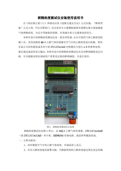
图1 酒精浓度测试仪示意图酒精浓度测试仪如图1所示,由MQ-3乙醇气体传感器、STC12C5A16AD (或STC12C5A32AD)单片机、EEPROM存储电路、液晶屏和键盘组成。
一、主要功能有:1、实时测量空气中的乙醇气体浓度,在液晶屏上显示。
2、具有乙醇浓度超高报警功能,当测量得到的乙醇浓度超过预先设定的阈值,则红灯报警。
3、醉酒阈值可存储至EEPROM存储器,并在液晶屏显示。
系统掉电后醉酒阈值不失,可以保持。
4、醉酒阈值可以通过按键修改并保存。
二、安装说明1、全部为直插元器件。
2、底板有万能板和PCB板两种。
如果要自己安装的话,PCB板好装,万能板难装,没有丰富的焊装经验,不建议自己安装万能板套件。
3、没有焊装把握的客户可以买成品,印制板的另收安装调试费40元,万能板的另收安装调试费60元。
电路装好,程序下好,功能调好发货。
安装调试费时费力,不还价,望谅解。
三、调试说明1、套件焊好后,不要急于上电,首先用万用表电阻档量一下电路板的GND 和5V电源之间是否短路。
短路切不可上电。
2、如果不短路,再接上USB电源,用万用表电压档测量5V和GND之间的电压是否正常,如果电压不正常,速断电检查。
3、一切正常,可以下载程序了。
打开STC下载软件,选择芯片型号,导入hex文件,设置波特率(两项都低于4800bps),下载程序,调试运行。
ATT7022B用户手册中文版210-SD-109_V1.0
ATT7022B 用户手册目 录第一部分 芯片介绍 (4)§ 1.1 芯片特性 (4)§ 1.2功能简介 (5)§ 1.3 内部框图 (5)§1.4 引脚定义 (6)§1.5 应用示意图 (9)第二部分 系统功能 (10)§2.1 电源监控电路 (10)§2.2 系统复位 (10)§2.3 模数转换 (11)§2.4 有功功率测量 (12)§2.5 有功能量测量 (12)§2.6 无功功率测量 (13)§2.7 无功能量测量 (14)§2.8 视在功率测量 (14)§2.9 视在能量测量 (15)§2.10 电压有效值测量 (16)§2.11 电流有效值测量 (16)§2.12 电压线频率测量 (16)§2.13 功率因数测量 (17)§2.15 电压夹角测量 (17)§2.16 电压相序检测 (17)§2.17 电流相序检测 (18)§2.18 起动潜动设置 (18)§2.19 功率方向判断 (18)§2.20 失压检测 (18)§2.21 硬件端口检测 (19)§2.22 片上温度检测 (19)§2.23 基波谐波测量功能 (19)§2.24 三相三线与三相四线应用 (22)§2.25 能量脉冲输出 (22)§2.26 参数输出寄存器定义 (23)§2.27 参数输出寄存器说明 (27)第三部分 校表方法 (33)§3.1 软件校表 (33)§3.2 校表寄存器定义 (34)§3.3 校表寄存器说明 (35)第四部分 SPI通讯接口 (45)§4.1 SPI通讯接口介绍 (45)§4.2 SPI读操作 (46)§4.3 SPI写操作 (47)§4.4 SPI写特殊命令操作 (48)第五部分 电气特性 (50)§5.1 电气参数 (50)§5.2 芯片封装 (51)第一部分 芯片介绍§ 1.1 芯片特性• 高精度在输入动态工作范围(1000:1),内非线性测量误差小于0.1% • 有功测量满足0.2S、0.5S,支持IEC 62053-22,GB/T 17883-1998 • 无功测量满足2级、3级,支持IEC 62053-23,GB/T 17882-1999 • 提供基波、谐波电能以及总电能测量功能• 提供视在电能测量功能• 提供正向和反向有功/无功电能数据• 提供有功、无功、视在功率参数• 提供功率因数、相角、线频率参数• 提供电压和电流有效值参数,有效值精度优于0.5%• 提供电压相序检测功能• 提供电流相序检测功能• 提供三相电流矢量和之有效值输出• 提供三相电压矢量和之有效值输出• 提供电压夹角测量功能• 提供失压判断功能• 具有反向功率指示• 提供有功、无功、视在校表脉冲输出• 提供基波有功、基波无功校表脉冲输出• 合相能量绝对值相加与代数相加可选• 内置温度测量传感器• 电表常数可调• 起动电流可调• 可准确测量到含21次谐波的有功、无功和视在功率• 支持增益和相位补偿,小电流非线性补偿• 具有SPI接口,方便与外部MCU通讯• 适用于三相三线和三相四线模式• 采用QFP44封装• 单+5V供电ATT7022B是一颗高精度三相电能专用计量芯片,适用于三相三线和三相四线应用。
- 1、下载文档前请自行甄别文档内容的完整性,平台不提供额外的编辑、内容补充、找答案等附加服务。
- 2、"仅部分预览"的文档,不可在线预览部分如存在完整性等问题,可反馈申请退款(可完整预览的文档不适用该条件!)。
- 3、如文档侵犯您的权益,请联系客服反馈,我们会尽快为您处理(人工客服工作时间:9:00-18:30)。
e 3UG3001 - UG3005
3.0A ULTRA-FAST GLASS PASSIVATED RECTIFIER
Features
Maximum Ratings and Electrical Characteristics
@ T A = 25°C unless otherwise specified
·Glass Passivated Die Construction ·Ultra-Fast Switching for High Efficiency ·Surge Overload Rating to 125A Peak ·Low Reverse Leakage Current
·
Lead Free Finish,RoHS Compliant (Note 4)
Mechanical Data
·Case: DO-201AD
·Case Material: Molded Plastic. UL Flammability Classification Rating 94V-0
·Moisture Sensitivity: Level 1 per J-STD-020C ·Terminals: Finish ¾Tin. Plated Leads Solderable per MIL-STD-202, Method 208·Polarity: Cathode Band ·Marking: Type Number
·Ordering Information: See Last Page ·
Weight: 1.1 grams (approximate)
Single phase, half wave, 60Hz, resistive or inductive load.For capacitive load, derate current by 20%.
Notes:
1.Valid provided that leads are maintained at ambient temperature at a distance of 9.5mm from the case.
2.Measured at 1.0MHz and applied reverse voltage of 4.0V DC.
3.Measured with I F = 0.5A, I R = 1.0A,I rr = 0.25A. See figure 5.
4.RoHS revision 13.2.2003. Glass and high temperature solder exemptions applied, see EU Directive Annex Notes 5 and 7.
5. Short duration pulse test used to minimize self-heating effect.
00.6
1.2
1.8
2.4
3.025
5075100125150175200
I ,A V E R A G E F O R W A R D R E C T I F I E D C U R R E N T (A )
(A V )T ,AMBIENT TEMPERATURE (C)Fig.1Forward Current Derating Curve
A
°0.01
0.1
1.0
10
0.6
0.8 1.0 1.2 1.4
I ,I N S T A N T A N E O U S F O R W A R D C U R R E N T (A )
F V ,INSTANTANEOUS FORWARD VOLTAGE (V)
Fig.2Typical Forward Characteristics
F
I ,P E A K F O R W A R D S U R G E C U R R E N T (A )
F S M 050
100
1501
10
100
NUMBER OF CYCLES AT 60Hz Fig.3Peak Forward Surge
Current
Set time base for 50/100ns/cm
+0.5A
0A -0.25A
-1.0A
Fig.5Reverse Recovery Time Characteristic and Test Circuit
110
100
1
10
100
C ,T O T A L C A P A C I T A N C E (p F )
T V ,REVERSE VOLTAGE (V)Fig.4Typical Total Capacitance
R
Ordering Information(Note 6)
Notes: 6. For packaging details, visit our website at /datasheets/ap02008.pdf
IMPORTANT NOTICE
Diodes Incorporated and its subsidiaries reserve the right to make modifications,enhancements,improvements,corrections or other changes without further notice to any product herein.Diodes Incorporated does not assume any liability arising out of the application or use of any product described herein;neither does it convey any license under its patent rights,nor the rights of others.The user of products in such applications shall assume all risks of such use and will agree to hold Diodes Incorporated and all the companies whose products are represented on our website,harmless against all damages.
LIFE SUPPORT
Diodes Incorporated products are not authorized for use as critical components in life support devices or systems without the expressed written approval of the President of Diodes Incorporated.。
