NSA3100系列保护装置操作使用
NSA说明书(新)(精品)

目录第一章NSA-3000系列分散式微机保护测控装置 (3)一概述 (3)二NSA-3111馈线保护测控装置 (10)三NSA-3112线路保护测控装置 (17)四NSA-3113线路光纤纵差保护测控装置 (24)五NSA-3121A站用变/接地变保护测控装置 (32)六NSA-3131A电容器保护测控装置 (38)七NSA-3133A电容器保护测控装置 (44)八NSA-3141A电动机保护测控装置 (50)九NSA-3151分段开关备用电源自投保护测控装置 (57)十NSA-3152A备用电源自投装置 (64)第二章NSA-3000系列变压器保护测控装置 (71)一概述 (71)二NSA-3171变压器差动保护装置 (72)三NSA-3181变压器后备保护测控装置 (83)四 NSA-3182变压器后备保护测控装置 (91)五NSA-3161变压器非电量保护装置 (98)六NSA-3179变压器保护装置 (107)第三章NSA3000系列辅助保护装置 (117)一NSA-SGJL事故解列装置 (117)第四章NSA-3000系列微机测控装置概述 (121)一微机测控装置性能简介 (122)二NSA-3101微机测控装置 (128)三NSA-3102微机测控装置 (137)四NSA-3103微机测控装置 (147)五NSA-3104微机测控装置 (156)六NSA-3102TQ微机测控装置 (165)第五章NSA-3000系列微机测控装置使用说明 (175)关于NSA-3000变电站综合自动化系统的所有技术和使用说明书的版权为南京电研电力自动化有限公司所有。
南京电研电力自动化有限公司保留对所有资料的修改和解释权,若有改动,恕不另行通知。
第一章NSA-3000系列分散式微机保护测控装置一概述1 NSA-3000系列分散式保护测控装置的典型设备及功能NSA-3000系列分散式低压保护测控装置是将保护功能及远动功能综合在一个装置中,该装置即“四合一”保护(保护、遥测、遥控、遥信)测控装置。
Eaton NW3100T33V3WP21 电子模具电路保护器说明说明书

Eaton NW3100T33V3WP21Eaton Series C electronic molded case circuit breaker, N-frame, NW, Electronic LS trip, Three-pole, 1000A, 690 Vac, 50 kAIC at 415 Vac, no term., World, Ambient temperature not marked on trip, 630, 800, 900, 1000A Adj. rating plugGeneral specificationsEaton Series C electronic molded case circuit breakerNW3100T33V3WP2178211486538518.5 in 11.5 in 11.5 in 46 lb Eaton Selling Policy 25-000, one (1) year from the date of installation of the Product or eighteen (18) months from the date of shipment of the Product, whichever occurs first.IEC Product NameCatalog NumberUPCProduct Length/Depth Product Height Product Width Product Weight WarrantyCertificationsAmbient temperature not marked on trip50 kAIC at 415 VacN630, 800, 900, 1000A adjustable rating plug 1000 AThree-poleNew design630, 800, 900, 1000A adjustableNWWorldWithout terminals690 V ACElectronic LS Application of Tap Rules to Molded Case Breaker TerminalsUL listed 100%-rated molded case circuit breakersApplication of Multi-Wire Terminals for Molded Case Circuit BreakersStrandAble terminals product aidMotor protection circuit breakers product aidCircuit breaker motor operators product aidPlug-in adapters for molded case circuit breakers product aid Current limiting Series C molded case circuit breakers product aid Multi-wire lugs product aidPower metering and monitoring with Modbus RTU product aid Breaker service centersEaton's Volume 4—Circuit ProtectionMolded case circuit breakers catalogCircuit breakers explainedCircuit Breakers ExplainedSeries C F-Frame molded case circuit breakersMOEM MCCB product selection guideSeries C G-Frame molded case circuit breakers time current curves Series C J-Frame molded case circuit breakers time current curves Eaton Specification Sheet - NW3100T33V3WP21Special features Interrupt ratingFrameRated permanent current Amperage Rating Number of polesTypeRating plugCircuit breaker type ClassTerminalsVoltage ratingTrip Type Application notesBrochuresCatalogsMultimediaSpecifications and datasheetsEaton Corporation plc Eaton House30 Pembroke Road Dublin 4, Ireland © 2023 Eaton. All Rights Reserved. Eaton is a registered trademark.All other trademarks areproperty of their respectiveowners./socialmedia。
3121GW站用变接地变保护测控装置技术说明书V10

一概述1.1 NSA-3000G系列分散式保护测控装置的典型设备及功能基于G平台的NSA-3000G系列分散式低压保护测控装置与以前大量生产的NSA-3000系列装置相比,在装置功能上主要整合了新一代变电站自动化系统的两大必备功能:●变电站的在线式五防功能●变电站的程序化操作功能变电站的在线式五防与程序化操作与变电站中的一次开关设备紧密联系,开关隔刀﹑地刀﹑接地桩的数量决定了需配置在线式五防闭锁节点的数量,而刀闸是手动刀闸还是电动刀闸决定了需配置的遥控节点的数量,为迎合这种需求,NSA-3000G 系列装置派生了很多型号。
从装置保护功能的不同区分为NSA-3000G系列及NSA-3000G1系列,●NSA-3000G系列保护功能与原NSA-3000系列保护功能及端子兼容●NSA-3000G1系列保护功能与端子布置遵循《广东电网公司10kV~110kV 保护技术规范》执行,功能较全。
●NSA-3000G与NSA-3000G1系列型号后加W或W-1则表明该型号装置含在线式五防功能及程序化操作功能。
W或W-1的区别主要在于五防闭锁节点的多少及遥控节点的多少,以适应手动刀闸控制及遥控电动刀闸控制的需要,型号的选择视实际工程而定。
针对中低压变电站中不同的保护测控对象,NSA-3000G系列的装置型号及功能如下:NSA-3111G用于35KV及以下电压等级的经消弧线圈接地或不接地系统中的馈电线路保护测控装置。
无在线式五防功能。
功能与NSA-3111兼容。
NSA-3111GW控装置。
增加在线式五防功能,主要用于10KV手动刀闸开关。
NSA-3111GW-1用于35KV及以下电压等级的经消弧线圈接地或不接地系统中的馈电线路保护测控装置。
增加在线式五防功能,主要用于35KV手动刀闸开关。
NSA-3111G1用于35KV及以下电压等级的经消弧线圈接地或不接地系统中的馈电线路保护测控装置。
无在线式五防功能。
保护功能符合《广东电网公司10kV~110kV保护技术规范》。
(完整版)NSA3100系列保护装置操作使用
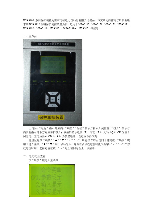
NSA3100系列保护装置为南京电研电力自动化有限公司出品,本文所述操作方法以较新版本的NSA3112线路保护测控装置为例,适用于NSA3112、NSA3151、NSA3171、NSA3181、NSA3182、NSA3111、NSA3131、NSA3131A、NSA3121等型号。
一、主界面上电后,“运行”指示灯应亮,“跳位”“合位”指示灯指示开关位置,“投入”指示灯亮表明指示灯下方对应保护投入;液晶屏显示电流(I)、有功(P)、无功(Q),CD为重合闸充电,充电后显示CD:1,Add为装置地址,设定后不再改变。
键盘区包括“确认”“▲”“▼”“←”“→”,所有操作均由这四个键完成。
“确认”键用于进入菜单,“▲”“▼”用于移动光标、翻页以及修改定值时更改数字,“←”“→”在修改定值时用于选择定值位数,“→”退出或回退至上一级菜单。
二、电流/电压查看按“确认”键进入主菜单按“▲”“▼”选择“输入显示”,“确认”后进入“输入显示”菜单选择“保护量”,即可查看保护装置所采集的二次电流、二次电压。
按“▲”“▼”翻页。
选择“测量量”,即可查看装置测量电流、有无功、功率因数等,该项目显示的电流值、有无功值是经装置设定的变比换算后计算出的。
按“▲”“▼”翻页。
三、查看报告在主菜单中选择“报告显示”“确认”后进入“报告显示”菜单选择“动作报告”后,系统要求输入报告序号,00为最新报告,用“←”“→”选择位数,用“▲”“▼”更改选中位的数字。
输入报告序号后按“确认”查看报告内容。
查看报告内容时,按“←”“→”翻页,按“▲”“▼”直接切换报告。
四、定值整定在主菜单办面选择“参数设定”“确认”后进入“参数设定”菜单1、保护定值区切换选择“装置参数”,“确认”后出现在该界面可以切换保护定值区,按“←”“→”将光标移至要修改的数字位置,按“▲”“▼”更改数字按“确认”键退出修改模式此时修改的数据已保存于RAM中,若此时装置掉电,则修改失败。
ENTECH3100A中文操作手册
3100A自动清罐仪简介3100A自动清罐仪利用干净的空气或者氮气通过循环抽气和充气来同时清洗一个或者多个不锈钢采样罐.抽气时,粗真空将用一级隔膜泵获得,高真空将用分子涡轮泵获得.加湿管用来加湿清洗气来帮助除去管路和采样罐内壁的挥发性有机物.利用加热带或加热箱对采样罐加热也可以帮助清除污染物.这一点很重要,因为在大于常压取样的时候,它经常导致在采样罐内形成冷凝物.3100A可以多次循环清洗管路和采样罐,可以因不同批次的采样罐设置不同充气压力和循环清洗次数.当样品气达到PPM级清洗要达到10到20次左右,如果是高PPM级的样品使用后,第一次清洗过后要在真空条件下保存一周左右,然后再一次清洗.3100A也可以单独使用某一个泵来工作,而且通过软件还可以检查系统是否漏气以及给清洗后的采样罐保持高真空状态.3100A可以自动进行清洗,也可以手动进行清洗.自动清洗利用软件设置清洗参数,手动清洗可以单独设置使用一级隔膜泵或者二级分子涡轮泵以及填充氮气.利用3100A的真空状态也可以对管路进行检漏和检验泵的最终的抽气能力.SmartLab控制软件介绍SmartLab仪器控制网络集中控制空气实验室仪器在一个通用的PC控制的Microsoft Windows 2000或者XP操作系统。
一个单独的计算机(奔腾Ⅱ400或者更好)控制GC/MS,7100预浓缩仪,7106CA罐自动进样器,7032迷你罐自动进样器,31位罐清洗,3100A自动清罐仪和4600动态稀释仪的操作。
所有Entech 总线上的外设都使用同样的控制电路。
模块化有许多好处,包括易于维修,减少配件数量,有利于使用者自己更好的了解产品。
熟悉了一个SmartLab产品后,其他的产品就变得更容易理解和操作。
软件使用USB HUB(可选件)可以将多个ENTECH产品连接到一台电脑上,当使用Microsoft Windows 2000或者XP操作系统时,软件检测到USB端口,然后安装USB驱动程序,即可控制ENTECH的产品.安装拆包把3100A从包装箱中取出,平稳的放在工作台上,地面上有合理位置摆放一级隔膜泵,同时还需要考虑如何来摆放采样罐以及如何设置零空气或者高纯氮气连接口.气路连接3100A需要使用高纯氮气或者零空气首先加水,通过3100A后的液位计观察水位液面,不能超过液位的一半,否则水就会进入气路,不能够获得足够高的真空状态.用1/4的铜管线从氮气出口到加湿器入口用1/8的铜管线从加湿器出口到3100A后的“FILL GAS IN”接口处.将采样罐用3/8螺母或者快速连接头连接在3100A支架上.将1/4软管安装在一级隔膜泵和3100A后的ROUGH PUMP接口处.检漏3100A在安装好后要检漏以保证系统在密闭条件下工作.检漏可以通过观察抽气后系统的真空度增加来确定系统密闭程度.用1/4接头将系统密闭.打开工作站,点泵1,当压力达到3个PSI以下后,点泵2,系统会很快达到2000毫脱以下.如果真空度不能在5分钟内达到50毫脱以下,则说明系统漏气或者管路中有积水.如果有水存在的话,管壁会很凉,可能因为那里的水来自汽化池被加热后产生的蒸气或者因为系统在35-40PSI压力下10分钟以上没有气体流动.如果管路里有水,请先确认水线在水位满刻度一半以下,然后做至少50次的清洗,而且在每次清洗时,要使分子涡轮泵至少运行1分钟.如果不能达到高真空或者不能保持压力,那么系统漏气就是存在的.漏气的地方可以用给系统加大气压然后使用电子检漏装置检查.如果在采样罐被连接到3100A支架上做真空检漏的时候漏气,要意识到漏气可能由于采样罐的阀漏气引起的.当系统使用泵2工作的时候,轻轻关闭采样罐的阀,观察高真空读度是否发生变化.发现漏气原因和找到解决漏气方法后,重新启动系统检漏测试.操作概要采样罐成功清洗包括很多因素,包括污染物的等级、最后样品的压力和湿度、存储的时间、采样罐内表面当前条件.最小温度和需要循环的次数是根据这些因素而变化的.两个泵都要使用是因为没有任何一个泵可以完全达到设计的要求.无油隔膜泵不能达到真空度很高的要求,最好的无油隔膜泵也不能把真空达到5-10毫脱以下.同样的,涡轮分子泵在高压力下保持10-20秒大体积气体抽取就会损坏.首先打开采样罐的阀,然后泵1抽粗真空,然后泵2再进一步抽真空.自动充气程序通过已经设置的泵1泵2和充气时间或者通过设置给定压力和真空度来达到.最典型的设置就是3次清洗采样罐,对于大多数采样罐来说,3次清洗足够了.在经过自动循环设定的次数后,系统将进入最后一次抽气过程,使用者通过一级泵和二级泵的工作将达到设定的真空度或时间,最后的真空度将保持在50-100毫脱之间.对环境样品的处理如果采样罐用来采集环境中的VOCS成分,每种成分物质的量仅在检测限的1-100倍左右,所以只需要很少的清洗次数就足够了.然而,在加压处理高湿度样品时,冷凝物会在罐内形成.聚合反应会发生在冷凝物离开污染物表面的时候.这些污染物会影响今后VOCS的取样和分析.通过提高温度增加清洗次数可以消除这些影响.通常情况下,温度从50度到100度的3或4次清洗就可以了.在进行这个操作的时候,设置填充压力大约25个PSI,确定加湿器水位保持在20%-50%之间.在缺省设置方法里,泵1、泵2和充气压力分别设置为2PSI、2000毫托和25PSI,清洗次数要看每批采样罐的数量和体积.在抽气压力达到后,会听到罐有气体流动声音,那表明抽气结束开始充气了.当使用支架时,要把采样罐吊在支架上.把加热带绑在能够最大限度的加热采样罐的地方.在打开采样罐的阀准备清洗前,要检漏.手动启动泵1到2PSI以下,然后启动高分子泵,如果压力在这样的条件下不能达到50-100毫托,那清洗就不能完成.允许系统在5分钟内达到最佳真空度,然后给采样罐加热,看真空度是否有改善.在检查了所有接头后,试着给采样罐的阀加热,然后观察真空度.一个坏的阀也会引起少量漏气.在关闭采样罐的阀的时候要轻用力,以免损坏阀.用大拇指和食指抠住阀就可以将阀很容易的打开和关闭.在达到合适的真空后,选择或者创建一个方法然后选择“GO”在“RUN”的显示窗口中.打开加热带或烘箱电源,对采样罐加热,采样罐在第二次循环的时候就可以达到合适的温度.在采样罐达到最后真空后,关闭采样罐的阀并关闭加热带或烘箱的电源.对污染样品的处理用来处理污染样品的采样罐不能在没有认真清洗或证明了没有清洗的情况下给环境样品进行使用.如果想重新做环境样品,一定要认真清洗。
3121GW站用变接地变保护测控装置技术说明书V10

一概述1.1 NSA-3000G系列分散式保护测控装置的典型设备及功能基于G平台的NSA-3000G系列分散式低压保护测控装置与以前大量生产的NSA-3000系列装置相比,在装置功能上主要整合了新一代变电站自动化系统的两大必备功能:●变电站的在线式五防功能●变电站的程序化操作功能变电站的在线式五防与程序化操作与变电站中的一次开关设备紧密联系,开关隔刀﹑地刀﹑接地桩的数量决定了需配置在线式五防闭锁节点的数量,而刀闸是手动刀闸还是电动刀闸决定了需配置的遥控节点的数量,为迎合这种需求,NSA-3000G 系列装置派生了很多型号。
从装置保护功能的不同区分为NSA-3000G系列及NSA-3000G1系列,●NSA-3000G系列保护功能与原NSA-3000系列保护功能及端子兼容●NSA-3000G1系列保护功能与端子布置遵循《广东电网公司10kV~110kV 保护技术规范》执行,功能较全。
●NSA-3000G与NSA-3000G1系列型号后加W或W-1则表明该型号装置含在线式五防功能及程序化操作功能。
W或W-1的区别主要在于五防闭锁节点的多少及遥控节点的多少,以适应手动刀闸控制及遥控电动刀闸控制的需要,型号的选择视实际工程而定。
针对中低压变电站中不同的保护测控对象,NSA-3000G系列的装置型号及功能如下:NSA-3111G用于35KV及以下电压等级的经消弧线圈接地或不接地系统中的馈电线路保护测控装置。
无在线式五防功能。
功能与NSA-3111兼容。
NSA-3111GW控装置。
增加在线式五防功能,主要用于10KV手动刀闸开关。
NSA-3111GW-1用于35KV及以下电压等级的经消弧线圈接地或不接地系统中的馈电线路保护测控装置。
增加在线式五防功能,主要用于35KV手动刀闸开关。
NSA-3111G1用于35KV及以下电压等级的经消弧线圈接地或不接地系统中的馈电线路保护测控装置。
无在线式五防功能。
保护功能符合《广东电网公司10kV~110kV保护技术规范》。
武汉百楚合锐赛尔NSA3100HF_v2[1].0
![武汉百楚合锐赛尔NSA3100HF_v2[1].0](https://img.taocdn.com/s3/m/0b172515cc175527072208fd.png)
FTU 技术使用说明书
南京电研电力自动化股份有限公司
版本声明 本说明书适用于 NSA3100HF 配网远方终端装置 V2.0 版本
南京电研电力自动化股份有限公司 南京高新技术开发区柳州北路 29 号 邮政编码:210031 联系电话:02558741699 网 址:
2.2.4 电源 ◆ 主电源:馈线终端主电源:交流 220V、PT 输出可选,具备两路输入自动切换功能; ◆ 备用电源:蓄电池(DC24V),交流电源消失后维持正常工作 8 小时;
NSA3100HF 配网自动化馈线终端
2.1.2 机械性能 ◆ 机箱防护性能:防护等级不低于 GB/T4208 规定的 IP43 及要求; ◆ 工业级产品:宽温度范围(-40 - +70),防磁、反震、防潮、防雷、防尘、防腐蚀; ◆ 壁挂式或柜式安装,扩展方便。
2.2 电气参数 2.2.1 额定数据
NACO
NSA3100HF 配网自动化馈线终端
1概述
1.1 应用范围
NSA3100HF主要用于中低压配电线路柱上开关、环网柜的实时监测和控制。
1.2 主要功能 ◆ 16路开关量变位遥信,开关量输入为24V光电隔离输入; ◆ 2组三相交流电压和1组三相交流电流模拟量输入(供保护和测量使用),其基本内容有 电压、电流、频率、功率及功率因数; ◆ 2路直流量变送器输入和一组蓄电池开始或停止活化遥控; ◆ 4路无源空节点遥控输出; ◆ 遥测越限告警及上传; ◆ 馈线停电自动识别并上传停电时刻负荷数据; ◆ 遥测定时保存功能,保存周期可设置; ◆ 装置告警、遥控操作、参数修改事件记录及事件SOE; ◆ 可就地、远方操作; ◆ 多种通讯规约可供选择:如101、104。 ◆ 配置多种接口,如:串口RS232、RS485及10/100M以太网通讯口。
3121GW站用变接地变保护测控装置技术说明书V1.0
一概述1.1 NSA-3000G系列分散式保护测控装置的典型设备及功能基于G平台的NSA-3000G系列分散式低压保护测控装置与以前大量生产的NSA-3000系列装置相比,在装置功能上主要整合了新一代变电站自动化系统的两大必备功能:●变电站的在线式五防功能●变电站的程序化操作功能变电站的在线式五防与程序化操作与变电站中的一次开关设备紧密联系,开关隔刀﹑地刀﹑接地桩的数量决定了需配置在线式五防闭锁节点的数量,而刀闸是手动刀闸还是电动刀闸决定了需配置的遥控节点的数量,为迎合这种需求,NSA-3000G 系列装置派生了很多型号。
从装置保护功能的不同区分为NSA-3000G系列及NSA-3000G1系列,●NSA-3000G系列保护功能与原NSA-3000系列保护功能及端子兼容●NSA-3000G1系列保护功能与端子布置遵循《广东电网公司10kV~110kV 保护技术规范》执行,功能较全。
●NSA-3000G与NSA-3000G1系列型号后加W或W-1则表明该型号装置含在线式五防功能及程序化操作功能。
W或W-1的区别主要在于五防闭锁节点的多少及遥控节点的多少,以适应手动刀闸控制及遥控电动刀闸控制的需要,型号的选择视实际工程而定。
针对中低压变电站中不同的保护测控对象,NSA-3000G系列的装置型号及功能如下:NSA-3111G用于35KV及以下电压等级的经消弧线圈接地或不接地系统中的馈电线路保护测控装置。
无在线式五防功能。
功能与NSA-3111兼容。
NSA-3111GW控装置。
增加在线式五防功能,主要用于10KV手动刀闸开关。
NSA-3111GW-1用于35KV及以下电压等级的经消弧线圈接地或不接地系统中的馈电线路保护测控装置。
增加在线式五防功能,主要用于35KV手动刀闸开关。
NSA-3111G1用于35KV及以下电压等级的经消弧线圈接地或不接地系统中的馈电线路保护测控装置。
无在线式五防功能。
保护功能符合《广东电网公司10kV~110kV保护技术规范》。
NSA3100HV电压监测仪

NSA3100HF定值整定说明

适用范围:1202 2201 2101 1203说明:1. 出口保持时间:分合闸动作出口保持时间。
2. 遥信防抖时间:在设定范围内遥信动作不产生信号。
3. A侧B侧电压额定值,根据接入电压额定值设置。
默认电源侧为A侧,负荷侧为B侧。
4.电池自动活化:投入时,按照活化和充电时间参数来自动放电活化和充电。
5.电源报警:电压采样值低于额定值80%报警。
保护定值保护整定说明1.遮断电流闭锁:当电流值大于整定值,闭锁跳闸。
不需要时整最大值且把控制字退出。
2.故障电流检测:用于合闸后在合闸闭锁判别时间内判断是否有故障。
不需要时整最大值且把控制字退出。
3.有压合闸:开关在分位,一侧电压大于整定值,达到延时后合闸。
有压定值大小、延时动作时间、是否投入均可设置。
4.失压跳闸:开关在合位,且开关两侧电压都低于无压定值,达到延时后分闸。
无压定值大小、延时动作时间、是否投入均可设置。
5.零压跳闸:合闸后在零压检测时间内检测到零序电压立刻分闸并闭锁合闸,在整定时间外检测到零压不跳闸。
不需要时整最大值且把控制字退出。
6.合闸闭锁:合闸后在合闸闭锁判别时间内检测失压。
可通过控制字选择是否需要判断故障电流。
(控制字投入)失压且有故障电流,合闸闭锁。
(控制字不投入)失压则合闸闭锁。
7.残压闭锁:开关在跳位,任一侧电压达到残压整定值50ms,并且在残压判别时间内消失。
闭锁另一侧有压合闸。
残压判别时间一般小于有压合闸时间和单侧有压合闸时间。
8.合闸闭锁、残压闭锁不自动复归,需合上开关20s、两侧有压20s、未闭锁侧有压合闸或通过遥控、按键操作复归。
9.联络方式:开关在分位,开关两侧均有电压闭锁合闸。
开关两侧有压保持30s以上,单侧失压后经延时后合闸,延时时间可设置。
注意:(联络方式下有压延时合闸功能自动退出)所有有关电压大小的定值,有压无压定值两侧使用同一个,为额定电压的百分数。
MA3100类II过流保护器商品说明书

Class IIIClass II 100kA* (10/350µs)5kA (8/20µs)*Total over a 3 phase systemCascade Effect Examplestandalone device and in cascade coordination with Class I lightning arrester. A single width module withstands surge currents up to 40,000A with an 8/20µs waveform. Class I I arresters are available in single width modules for maximum user flexibility, double width modules for all-mode protection on single phase systems and quad width modules for all-mode protection on three phase systems. The Class II modules have remote monitoring capabilities as a standard feature. Voltage free, normally open, normally closed contacts can beused for a variety of monitoring tasks.The MA3145 Class II surge current arrestor has a Short CircuitCurrent rating (SCCR) of 200kA which removes the need for externalfusing and reduces installation cost.The MA3100 range offers cost effective surge protection for applications described by IEC 61312, where the AC mains supply can carry a partial share of the lightning surge current. Class I surge protectors (rated according to IEC 61643) are designed to carry up to 50kA (10/350µs). Class II surge protectors are characterized by their ability to protect against 8/20µs impulses up to 40kA, possibly resulting from the operation of a class I device. Finally Class III devices are used to protect individual pieces of equipment. An excellent example of a class III device is the MA15.Coordinated IEC 61643 Class I, Class II and Class III surge protectionEaton Electric Limited,Great Marlings, Butterfield, Luton Beds, LU2 8DL, UK.Tel: + 44 (0)1582 723633 Fax: + 44 (0)1582 422283E-mail:********************© 2016 EatonAll Rights ReservedPublication No. EPS 901-173 RevC September 20161TN-C-S SystemVariations for IT ORMA3145-230-1-R MA3145-230-2-RMA3145-230-1-R Variations for TTT o order Class II surge protection devices, specify -R = Remote contacts present MA31 = (Product range name)120 = operating voltage 230 = operating voltage 1 = 1 module width 2 = 2 module widths 45 = Product rangeFigure 1 Class II dimensionsBA Class II Surge Protection DeviceT echnical dataDimensions (see Fig. 1 for A and B)IEC category/VDE requirement class:Nominal voltage U n :Max. continuous operating voltage U Lightning test current Iimp (10/350µs)Test standards: UL1449 3rd Edition; IEC 61643-11:2011-03MA3145-230-1-REUROPE (EMEA): +44 (0)1582 723633 ********************THE AMERICAS: +1 800 835 7075*********************ASIA-PACIFIC: +65 6 645 9888***********************The given data is only intended as a productdescription and should not be regarded as a legal warranty of properties or guarantee. In the interest of further technical developments, we reserve the right to make design changes.Eaton Electric Limited,Great Marlings, Butterfield, Luton Beds, LU2 8DL, UK.Tel: + 44 (0)1582 723633 Fax: + 44 (0)1582 422283E-mail:********************© 2016 EatonAll Rights ReservedPublication No. EPS 901-173 RevC 190916September 20162MTL MA3145 (I & II Pole) Class IISeptember 2016。
sensor electronics corporation 3100 传输器操作手册说明书
SEC 3100 TransmitterInstruction and Operation ManualSensor Electronics Corporation5500 Lincoln DriveMinneapolis, Minnesota 55436 USA(952) 938-9486 Fax (952) 938-9617Web site Part Number 3100-EXP-MANUALREV 121107-001Sensor Electronics CorporationSensor Electronics Corporation (SEC) designs and manufactures innovative fixed system gas detection quality and service are uncompromising. our products with a two-year warranty on all Gas Detect Individually designed maintenance pack ic customer needs. Service begins with Sensor Electronics Corporation (SEC) warrants anufactured by SEC to be free from defects in cluding rough handling, mechanical damage, alteration or repair. This Year 2000 ComplianceAll Sensor Electronics products have b d by Sensor Electronics to accuratelyequipment, for combustible gases, oxygen, carbon dioxide and toxic gases.CommitmentOur We back each of materials and workmanship. We offer technical support, user training and on-site service and maintenance of equipment to meet the needs of our customers.ion Serviceages are available for specif verification of the system installation that includes an initial system check and calibration. We then offer customer training programs (on-site and at factory) to insure that technical personnel fully understand operation and maintenance procedures. When on-the-spot assistance is required, service representatives are available to handle any questions or problems immediately.Warrantyproducts m workmanship and materials for a period of two (2) years from date of shipment from the factory. Any parts returned freight pre-paid to the factory and found defective within the warranty would be repaired or replaced, at SEC's option. SEC will return repaired or replaced equipment pre-paid lowest cost freight. This warranty does not apply to items, which by their nature are subject to deterioration or consumption in normal service. Such items may include: Fuses and Batteries.y abuse in Warranty is voided b warranty covers the full extent of SEC liability and SEC is not responsible for removal, replacement costs, local repair costs, transportation costs or contingent expenses incurred without prior written approval. Sensor Electronics Corporation's obligation under this warranty shall be limited to repair or replacement of any product that has been returned to Sensor Electronics Corporation for warranty consideration. This warranty is expressly in lieu of any and all other warranties expressed or implied, and all other obligations or liabilities on the part of Sensor Electronics Corporation including but not limited to, the fitness for a particular purpose. In no event shall Sensor Electronics Corporation be liable for direct, incidental, or consequential loss or damage of any kind connected with the use of it's products or failure to function or operate properly.een tested and are certifie process date/time and date/time related data from, into and between the 20th and 21st centuries. Sensor Electronics products neither contain nor create any logical or mathematical inconsistency, will not malfunction, and will not cease to function when processing date/time data. Please contact Sensor Electronics for further information.Table of Contents I. SPECIFICATIONSDESCRIPTIONII. GENERALIII. OPERATIONInstallation and StartupCodesFaultIV. MAGNETIC SWITCH OPERATIONV. FIGURESFigure 1 – Overall LayoutFigure 2 – SEC 3100 WiringFigure 3 – SEC Sensor Separation KitI. SPECIFICATIONSModel:SEC 3100 TransmitterFor use with:SEC Millenium and SEC Signature series infrared sensors and SEC 3000 Toxic and Oxygen gas sensors. Part Number: SEC 3100100Output (analog):4-20 mA (Source type), max. 1000 Ohm load at 24 VDC supply voltageOutput (digital):RS485 LAN (isolated)Output (relays):Three (3) Alarm, Low, Mid High. One (1) FaultRated for 8 Amps 30 VDC or 220VACDisplay:LCD (backlit)Construction:Epoxy coated aluminumClass 1, Division 1, Groups B, C and DOperating Temperature Rating:-40° to +158° F at 0 to 99% RH (non-condensing)(-20° to +70°C)Operating Voltage:24 VDCOperating range: 18 to 30 VDC measured at the detector headMax. Current Draw: (at 24 VDC with sensor)Average: 250 mAPeak: 500 mAInstallation Category: Cat. I, Pollution Degree 2II GENERAL DESCRIPTIONCONVENTIONSThe following conventions are used in this manual.!Warning StatementVDC (DC Voltage)SEC 3100The SEC 3100 transmitter is designed to be used with the SEC Millenium, SEC Signature infrared gas sensors or SEC 3000 toxic gas detectors. The SEC 3100 is a microprocessor based intelligent transmitter continuously monitoring information from the gas sensor. The LCD of the SEC 3100 displays the gas concentration and sensor status. The SEC 3100 has one (1) “Alarm” LED and one (1) “Status” LED. The SEC 3100 also has three (3) magnetic switches located around the circumference of the unit. This manual will describe the operation and use of the SEC 3100 transmitter.Features•Explosion Proof•Back lighted LCD Display•Low Cost•Plug and play toxic, oxygen and combustible gas sensors•Self-check system•4-20 mA ouput•RS-485 Interface (Isolated)•Optional alarm and fault relays•Non-intrusive programming•Non-intrusive calibration•Removable, non-volatile, time stamped data logging•Optional IS barrier•Digital communication link to SEC 3000 and SEC Millenium Gas Detectors•Multi port housing for easy installationIII. OPERATIONInstallation and Startup!Warning: The user shall be made aware that if the equipment is used in a manner not specified by the manufacturer, the protection provided by the equipment may be impaired.The first step in the installation process is to establish a mounting location for the SEC 3100 transmitter and gas sensor. Select a location that is typical of the atmosphere to be monitored or close to the anticipated source of a dangerous gas.It is very important that the SEC 3100 and gas sensor be properly located enabling it to provide maximum protection. The most effective number and placement of sensors vary depending on the conditions of the application. When determining where to locate gas sensors the following factors should be considered.•What are the characteristics of the gas that is to be detected? Is it lighter or heavier than air? If it is lighter than air the sensor should be placed above the potential gas leak. Place the sensor close to the floor for gases that are heavier than air. Note that air currents can cause a gas that is heavier than air torise. In addition, if the temperature of the gas is hotter than ambient air or mixed with gases that are lighter than air, it could also rise.•How rapidly will the gas diffuse into the ambient air? Select a location for the sensor that is close to the anticipated source of a gas leak.•Wind or ventilation characteristics of the immediate area must also be considered. Movement of air may cause gas to accumulate more heavily in one area than in another. The detector should be placed in the areas where the most concentrated accumulation of gas is anticipated. For outdoor applications with strong wind conditions, it may require the sensors to be mounted closer together and on the down wind side, to the anticipated area of a gas leak. Also take into consideration for indoor applications, the fact that many ventilation systems do not operate continuously.•The sensor should be accessible for maintenance.•Excessive heat or vibration can cause premature failure of any electronic device and should be avoided if possible.•Follow all national and local installation codes and practices.The SEC 3100 has three (3) ¾” NPT threaded connectors for mounting and wiring the sensor and transmitter into a permanent installation.Field wiring connections are made on the backside of the SEC 3100 printed circuit board (PCB). For wiring details refer to Figure 2 in the back of the manual.Power wire sizing:0 to 500 feet, recommended wire gauge size 16 AWG501 to 1000 feet, recommended wire gauge size 14 AWGShielded cable is recommended. Wiring should be installed in medal conduit with no other cabling in the same conduit.Warm-upWhen power is applied to the SEC 3100, it enters a one (1) minute warm-up mode. The output current will be 0.8 mA during the warm up time period. At the end of the warm-up period with no faults present, the SEC 3100 automatically enters the normal operating mode (4.0 mA with no gas present). If a fault is present after warm-up, the detector current output and LCD will indicate a fault. The Fault LED will also indicate the fault.NormalIn the normal operating mode, the 4 to 20 mA signal levels correspond to the detected gas concentration. The transmitter continuously checks for and displays system faults or initiation of calibration and automatically changes to the appropriate mode.The 4 to 20 mA output of the SEC 3100 sensor is a non-isolated current source.Current Output and Corresponding StatusOnce the fault is cleared the SEC 3100 will atomatically resume normal operation.Flash Rate Output Current Unit StatusLabelPossible Problem1 4-20ma Unit Running Unit is measuring gas and adjusting 4-20ma output accordingly.2 2.2ma Unit Zero Calibrating Unit going through its zero calibration procedure.3 2.0ma Unit Spanning Unit going through its spanning procedure.5 0.8ma Unit Warm-up Only for one minute after unit power-up6 0.0ma Power-up Fault Hard Fault (refer to gas sensor manual)7 1.6maCalibrationFault 1. AttemptUnit Span with no gas 2. AttemptUnit Zero with gas8 NA NA Currently Not Used9 0.0ma Unit Fault Hard Fault (refer to gas sensor manual)10 1.0ma Optics Fault Clean sensor’s windows11 1.2ma Zero Drift Fault Hard Fault (refer to gas sensor manual)12 0.0maConfigurationFault HardFault (refer to gas sensor manual)16 0.2ma Reference Channel Fault Hard Fault (refer to gas sensor manual)17 0.4ma Active Channel Fault Hard Fault or Unit Zero with gasIV. MAGNETIC SWITCH OPERATIONThe SEC 3100 has three (3) magnetic switch pickups on the Display PCB. The picture below shows the location of the magnetic switches labeled UP, DOWN and ENTER. Placing a magnet in close proximity to one of the switches will cause the following operations to occur.Switch Operation ENTER Enter Menu Mode, Selects a menu to Enter UP Moves up through Menu selections DOWN Moves down through Menu selectionsFor further details on gas sensor calibration refer to the appropriate SEC sensor instruction manual.The LCD contrast potentiometer, (POT1) is located under the protective faceplate shown above on the front side (LCD side) of PCB to the left of the LCD.Gas Sensor Port (1 x ¾h)SEC 3000SEC MilleniumMagnetic Switch (3)Field Wiring Port (2 x ¾h )¾Power¾4-20 mA¾RS485 (MODBUS) ¾Alarm RelaysFault LED Green OK Memory Data CardSlotRed FaultLCD Display:Real Time Status Gas TypeGas Concentration Fault Identification RangeID NumberMemory Card Status Interactive MenusCalibration Relay Programming ID & Zone NumberMounting holes (2)Alarm LED Green OK Yellow Low Alarm Orange Mid Alarm Red High AlarmV. MENU OPERATIONInital Power Up Sequence of the SEC 3100In normal operating mode. Actual gas concentration will be displayed to the left of ID #, Range, Gas Type, MC (Memory Card) status.Selecting Enter when the SEC 3100 in in normal operating mode will advance to the following display:Selecting Enter will allow the operator to safely remove the Memory Card. Arrow DownEntering the INFO menu will display the following screenSelecting Enter at UNIT INFO displays the following: SN is the SEC 3100 serial number. VER is the SEC 3100 software version number. Selecting Enter againwill return the display to the main info menu.The following are the other INFO sub displays and descriptions. To return back to the main INFO menu from the sub menus, select Enter.Sensor Status Menu TYP: Sensor type (0.0 is a SEC 3000, 32.0 is SEC Millenium)SN: Sensor serial number. VER: Version of sensor software. CAL: Calibration date of sensor.Sensor Status Menu RBR COUNT : SEC information ICE COUNT : SEC information. BATTERY : Displays status of SEC 3100 batteryMain Menu and Sub MenusEnterUsed to calibrate the gas sensor.Down ArrowAlarm MenuUsed to setalarm level set points andparameters.Down ArrowRelay MenuFor setting alarm relay On & Off delay &Energized states.Down ArrowNetwork MenuDown ArrowHide Menu Hide is used toblank thedisplay up tolow alarm settingDown ArrowSelf Test MenuGenerates asignal on the display, RS485 4-20 mADown MenuDate Time MenuDown ArrowExit back tonormalCalibration MenuEnter Using the Up and Down arrows allows the operator to move the cursor (*) to select a function.To Zero the sensor apply clean air (N2 for an oxygen sensor) and select enter. The following will be displayed.Then the following will be displayed.Once complete the following will be displayed. The sensor has been successfully zeroed.Arrow down to CAL. VAL to verify the span gas calibration value matches the value of the span gas calibration on hand. If not, select Enter and the following screen will appear.Using the Up and Down arrows will allow the operator to change the calibration gas value of the sensor to match the calibration gas used to span the sensor. Once the correct value is displayed select Enter and the sensor will be uploaded with the new calibration gas value.To Span the sensor with calibration gas use the Up and Down arrows to select the following display.Apply span gas to the sensor for the appropriate amount of time in order for the sensor to stabilize. The gas reading is displayed to the right of ZERO. Once stable select Enter. This will go the display:If calibration span gas is still present the display will read:Apply clean air to the sensor to reduce this reading.The display will advance to the following:This completes the calibration and the device can be put back into the normal operating mode.Arrow Down toEnterEnter again and the SEC 3100 returns to normal operation.Alarm MenuEnterEnterSelect the Alarm Relay (LOW, MID, HI) using the down arrow. Once the cursor is on the alarm relay you wish to configure, hold the magnet over Enter. The example LOW will be used. The same operations can be used to set the MID or HI relays.Selecting Enter will display the following screen allowing the alarm set point to beprogrammed. Using the Up and Down arrows will change the set point. Once the correct set point is displayed select Enter and the new value will be accepted.Arrow DownSelecting Enter will allow the operator to change the operation of the relay operation from Non-Latching (NO) to Latching (YES).Arrow DownSelecting Enter will allow the operator to change the operation of the relay operation from Active HI to Active LOW. HI activates the relay on a rising alarm level. LOW actives the relay when the alarm threshold falls below the alarm set point. Once the correct operation is selected, use the Down arrow to advance to the next menu item.Arrow DownSelecting Exit will advance to the next menu.This menu will allow the operator to select another relay to program. Or select Exit and the next display will be:Selecting Enter on this display will put the SEC 3100 back into normal operation.Relay MenuSelecting Enter will advance to the following menu.Arrow down to the next screen will beSelect the Alarm Relay (LOW, MID, HI, FAULT) that is to be configured using the down arrow. Once the cursor is on the correct alarm relay, hold the magnet over Enter. The example LOW will be used. The same operations can be used to set the MID, HI, or FAULT relays.Select EnterSelect EnterUsing the Up and Down arrows the operator can change the ON delay time for the relay to actuate after the alarm threshold has been exceeded. The time is measured in seconds (0-255). Once the correct time is displayed select Enter to accept the new value. Then Exit the menu and proceed on to the next selection. In this example the Low alarm relay will actuate 30 seconds after the Low set point is exceeded.Select EnterSelect EnterUsing the Up and Down arrows the operator can change the OFF delay time for the relay to turn OFF after the reading has decreased below the alarm point threshold. The time is measured in seconds (0-255). Once the correct time is displayed select Enter to accept the new value. Then Exit the menu and proceed on to the next selection.In this example the Low alarm relay will stay energized for 60 seconds after the alarm has cleared.Arrow DownSelecting Enter will allow the operator to change the operation of the relay coil from normally de-energized (ENERGIZED NO) to normally energized (ENERGIZED YES). Once the correct operation is selected, use the Down arrow to advance to the EXIT menu. Select Enter to go back to the Relay MenuThis menu will allow the operator to select another relay to program. Or select Exit and the next display will be:Arrow Down to ExitEnterSelecting Enter will return the SEC 3100 into normal operation.Network MenuSelect EnterSelect Enter to change the Zone number of the SEC 3100.Use the Up and Down Arrows change the Zone number (0-255). Once the correct Zone number is displayed select Enter.Arrow Down to ID. To change the ID number select Enter. Use the Up and Down Arrows to change the ID number (0-255). Once the correct ID number is displayed select Enter.Arrow Down to Online.Using Enter the operator can toggle between Online YES and Online NO. Online YES turns on the MODUS RS485 communication. Online NO turns the MODBUS RS485 communication off.Arrow Down to ExitEnterHide MenuUsing Enter the operator can toggle between Hide YES and Hide NO.The Hide function allows the operator to not display the gas reading until the Low Alarm threshold is exceeded. All outputs will function as normal when the Hide mode selected to YES.Self Test MenuSelecting Enter for the Self Test will make the sensor generate a 4-20 mA input into the SEC 3100 from 4 mA to 20 mA (0-fullscale). In the self test mode the SEC 3100 outputs are fully functional. The SEC 3100 will display the rising gas level, the 4-20 mA output will increase to 20 mA, the relays will actuate and the RS485 information will be transmitted to the control system. The following screen will be displayedOnce the unit reaches full scale the SEC 3100 automatically returns to normal.Time Date MenuEntering this menu will allow the operator to set the time and date of the SEC 3100 real time clock.Selecting Enter will locate a cursor (*) above the number allowing the operator to use the Up Down arrows to increase or decrease the numbers. Once the correct number is displayed, select Enter with the magnet and the cursor will advance to the next number.Date is MM/DD/YYYY. Time is HH/MM/SS. Below is an example.Enter from above display.Arrow Up one number.EnterContinue with the sequence until the correct date appears. Then select Enter and the following will be displayed.programmed, select Enter and arrow down to Exit.Select EnterSelecting Enter again will return the SEC 3100 to normal operation.Diagnostics MenuThe Diagnostics Menu will allow the operator to enter the Locator Mode and Toggle Relays on and off to verify operation.Selecting Enter will display the following:The Locator function is normally generated by the SEC 3500 operator interface. It can be used at the SEC 3100 to function as a lamp test. Selecting Enter will turn the Locator on.The Alarm and Fault LEDs will flash red and green alternately.Selecting Enter again will turn the Locator function off.Arrow Down to Toggle Relays (manual relay control)Selecting Enter will display the following:Select the Alarm Relay (LOW, MID, HI, FAULT) that is to be configured using the down arrow. Once the cursor is on the correct alarm relay, hold the magnet over Enter. The example LOW will be used. The same operations can be used to manually control the MID, HI, or FAULT relays.Selecting Enter will manually turn on the relay, selecting Enter again will turn off the relay.Reset Relays MenuThe Reset Reset relays Menu will allow the operator to reset latched relays.Latched relays will be indicated by a blue flashing Alarm LED. Select Enter and any latched relays will be reset.V. FIGURESFigure 1 – Overall LayoutFigure 2 – SEC 3100 WiringFigure 3 – SEC Sensor Separation KitFigure 4 – Mounting SEC 3100 and SEC Millenium Figure 5 – Mounting SEC 3100 and SEC 3000Relay ID & Zone NumberMagnetic Switch (3)Fault LED Green OK Red FaultAlarm LED OK Low Alarm Mid AlarmTB 3(1) WHITE TB 2(1) 4-20 mA ANALOG OUTPUT (12) LOW ALARM N.C.(11) LOW ALARM COMMON RELAY WIRINGFIGURE 4FIGURE 5SEC 3100 – SEC 3000 Mounting。
施耐德综保操作说明

Building a New Electric World
Sepam 20/40系列高级人机界面 系列高级人机界面
MVSEPAM – 2006-5- For internal use only
2
高级人机界面( 高级人机界面( UMI) )
128 x 64 象素, 显示行数、符号和文字的大小由语言版本和屏 幕决定 2 种不同版本的屏幕背景可供选择 : 工厂版本: 英文 用户定制版本:中文
6
UMI / 指示灯
1 1
灯指示设备正常通电
灯指示设备此时不可用
Sepam电源刚接通时,此灯闪烁,屏幕上有文字Sepam且进度指示器 不断变化,此为保护上电自检状态,约20秒后后如没有检测到内部故 障,Sepam进入正常运行状态,此灯熄灭
Sepam故障时,此灯亮或闪烁,屏幕上出现扳手符号,后面有或没有数字 标准标签上有9个可编辑的指示灯 (用户可以用SFT2841软件重新编辑和打 印指示灯标签)
22
蓝键) 参数和保护整定 (蓝键 - 一般特性 蓝键
在一般设定菜单中,可以修改如下数 据: 不需要密码 – 语言 (英语, 中文) 需要密码 – (10I/Is, TMS) – 时间 – 输出测试
MVSEPAM – 2006-5- For internal use only
23
蓝键) 参数和保护整定 (蓝键 – 保护功能 蓝键
16
白键)电流操作 (白键 报警 白键
已确认的报警
报警 “详细信息” 循环 详细信息
此循环显示未被清除的报警的详细 信息(最多16个) 未被确认的报警由左图的符号标识
未确认的报警
清除键:
MA3100电压保护器安装说明 用户手册说明书

Cat. No.
MA3145-120-1-R MA3145-230-1-R MA3145-120-2-R MA3145-230-2-R MA3145-120-4-R MA3145-230-4-R
Voltage Specifications
Service Voltage Poles
For more information contact your local MTL rep: /contact/
801643 Rev C 01/08/10
CONGRATULATIONS! YOU HAVE JUST PURCHASED THE BEST SURGE PROTECTION IN THE INDUSTRY! Adhering to these instructions guarantees maximum performance of this protection device.
NOTE: Keep conductor length as short as possible with no sharp bends. Do not loop or coil wires.
4. REMOVAL If the blown indicator tab is visible on any of the multiple pole units, then the entire unit has reached the end of its life and must be replaced. To remove, push up on the unit and rock the top off the 35mm DIN rail (See Figure 3).
NSA3000系列装置LFP规约协议解析

LFP规约协议解析NACO公司NSA系列继电保护规约,采用了多种通讯协议,这里以NSA3152A备自投保护装置和NSA3112线路保护装置为基础,解析串口LFP报文格式内容。
1.通讯接口:1.1接口标准:CAN/RS-485/TCP1.2通讯格式:异步,一位起始位,八位数据位,一位停止位,无校验位。
1.3通讯速率:4800~100Kbps。
1.4通讯方式:主从方式。
2.注:①报文长度指特征码,分组数,分组序号,报文长度,报文内容长度之和。
②报文内容最大长度为250字节。
③代码和为地址码,特征码,分组数,分组序号,报文长度,报文内容总和的低16位值(单字节相加)④地址码范围为0-0FEH,其中0FFH为广播地址,0-0FEH为各保护地址⑤分组序号从1,分组数至少为1⑥报文内容可以为空3.报文类型:3.1特殊报文:ACK(06H) 接收正确NAK(015H) 接收不正确这两字节作为特征码出现在上行报文及下行报文中,无报文内容。
NAK是接收侧通知发送侧本次接收有误。
ACK有二种可能,其一通知发送侧本次接收正确,其二通知发送侧所要求的信息没有准备好或不存在。
(对于某一种保护装置,并非所有下行报文都有效)3.2 报文定义与交换:#define RCS_C1 0x40 /*对保护的故障报告,故障事件,自检报文,测距报文查询*/ #define RCS_C2 0x41 /*申请所有保护定值*/#define RCS_C3 0x42 /*指对一定序号的故障报告进行申请*/#define RCS_C4 0x43 /*申请模拟量:包括电流,电压,相位差*/#define RCS_C5 0x44 /*申请开关量*/#define RCS_C6 0x45 /*申请特定的自检报告*/#define RCS_C7 0x46 /*申请信号复归*/#define RCS_C8 0x47 /*修改保护内部时钟*/#define RCS_C9 0x48 /*修改保护定值*/#define RCS_C10 0x49 /*确认本次定值修改有效*/#define RCS_C11 0x4a /*改变当前运行定值区号*/#define RCS_C12 0x4b /*确认本次定值区号修改有效*/#define RCS_C13 0x4c /*申请定值区号*/#define RCS_C14 0x4e /*申请小电流接地数据*/#define RCS_C15 0x50 /*申请遥测*/#define RCS_C16 0x51 /*申请电度*/#define RCS_C17 0x52 /*遥控申请*/#define RCS_C18 0x53 /*遥控确认*/#define RCS_C19 0x54 /*申请全遥信*/#define RCS_C20 0x55 /*查询命令2,对遥信变位及SOE查询*/#define RCS_C21 0x56 /*申请计算电度*/#define RCS_C22 0x57 /*遥控撤消*/#define RCS_C23 0x58 /*电容器投切申请*/#define RCS_C24 0x59 /*电容器投切确认*/#define RCS_C25 0x5a /*小电流接地跳闸申请*/#define RCS_C26 0x5b /*小电流接地跳闸确认*/#define RCS_C27 0x5c /*同期合闸申请*/#define RCS_C28 0x5d /*同期合闸确认*/#define RCS_C29 0x5e /*无压合闸申请*/#define RCS_C30 0x5f /*无压合闸确认*/#define RCS_C31 0x60 /*电容器投切取消*/#define RCS_C32 0x61 /*小电流接地跳闸取消*/#define RCS_C33 0x62 /*同期合闸取消*/#define RCS_C34 0x63 /*无压合闸取消*/#define RCS_C35 0x64 /*申请装置类别*/#define RCS_SCADA 0x7f#define RCS_R1 0x40 /*简单的事件报告,带有绝对时间,仅指示保护跳闸,重合闸*/#define RCS_R2 0x41 /*定值上送*/#define RCS_R3 0x42 /*一次事故完整的报告*/#define RCS_R4 0x43 /*telemeter sending*/#define RCS_R5 0x44 /*yx sending*/#define RCS_R6 0x45 /*selfcheck report*/#define RCS_R7 0x46 /*新故障报告,主动上送,仅部分报告*/#define RCS_R8 0x47 /*新自检报告,主动上送*/#define RCS_R9 0x48 /*当前运行定值区号*/#define RCS_R10 0x49 /*COS,对C20查询上送*/#define RCS_R15 0x50 /*遥测上送*/#define RCS_R16 0x51 /*脉冲电度上送*/#define RCS_R17 0x52 /*遥控返校*/#define RCS_R18 0x53 /*遥控确认返回*/#define RCS_R19 0x54 /*全遥信上送*/#define RCS_R20 0x55 /*SOE,对C20查询上送*/#define RCS_R21 0x56 /*计算电度*/#define RCS_R22 0x57 /*测距报文,对C20查询上送*/#define RCS_R23 0x58 /*电容器投切返校*/#define RCS_R24 0x59 /*电容器投切确认返回*/#define RCS_R25 0x5a /*小电流接地跳闸返校*/#define RCS_R26 0x5b /*小电流接地跳闸返回*/#define RCS_R27 0x5c /*同期合闸返校*/#define RCS_R28 0x5d /*同期合闸确认返回*/#define RCS_R29 0x5e /*无压合闸返校*/#define RCS_R30 0x5f /*无压合闸确认返回*/#define RCS_R31 0x60 /*小电流接地数据*/#define RCS_R32 0x61 /*装置类别*//*NOTE:如用LON通讯,则不用C20查询,R10,R20和R22主动上送。
TX3113
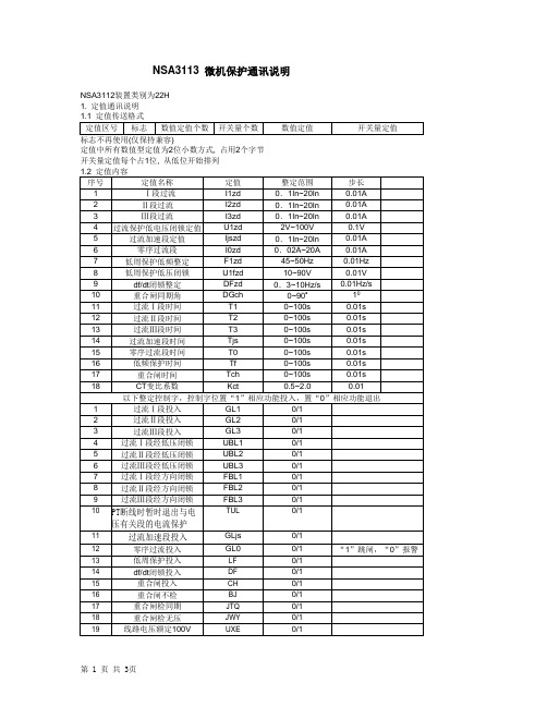
NSA3113 微机保护通讯说明NSA3112装置类别为22H
1. 定值通讯说明
定值中所有数值型定值为2位小数方式, 占用2个字节
开关量定值每个占1位, 从低位开始排列
2. 故障报告说明
第0位: 过流Ⅲ段动作
第1位: 过流Ⅱ段动作
第2位: 过流Ⅰ段动作
第3位: 合闸加速动作
第4位: 低周减载动作
第5位: 重合闸动作
第6位: 零序跳闸
第7位: 差动动作
第8位: 整组起动
动作事件中某位置1, 表示该位对应元件动作电流占2个字节, 2位固定小数, 单位为安培
选相占用1字节
0. 通道故障
1. 差流报警
2. 3U0报警
3. 事故总信号
4. 电源异常
5. 过负荷报警
6. 定值出错
7. 出口故障
8. 线路电压报警
9. PT断线
10. 频率异常
11. CT断线
12. TWJ异常
13. 控制回路断线
14. 弹簧未储能
15. 零序电流报警
3. 保护模拟量说明
0. 开入1
1. 开入2
2. 开入3
3. 开入4
4. 开入5
5. 开入6
6. 开入7
7. 开入8
8. 差动投入
9. 低周投入
10. 弹簧未储能
11. 闭锁重合
12. 遥控投入
13.TWJ
14.HWJ
15. KKJ
6. 遥测量说明
11位为满刻度, IA,IC,对应1.2倍额定值P, Q, COSφ对应1倍额定值12位为符号位。
- 1、下载文档前请自行甄别文档内容的完整性,平台不提供额外的编辑、内容补充、找答案等附加服务。
- 2、"仅部分预览"的文档,不可在线预览部分如存在完整性等问题,可反馈申请退款(可完整预览的文档不适用该条件!)。
- 3、如文档侵犯您的权益,请联系客服反馈,我们会尽快为您处理(人工客服工作时间:9:00-18:30)。
NSA3100系列保护装置为南京电研电力自动化有限公司出品,本文所述操作方法以较新版本的NSA3112线路保护测控装置为例,适用于NSA3112、NSA3151、NSA3171、NSA3181、NSA3182、NSA3111、NSA3131、NSA3131A、NSA3121等型号。
一、主界面
上电后,“运行”指示灯应亮,“跳位”“合位”指示灯指示开关位置,“投入”指示灯亮表明指示灯下方对应保护投入;液晶屏显示电流(I)、有功(P)、无功(Q),CD为重合闸充电,充电后显示CD:1,Add为装置地址,设定后不再改变。
键盘区包括“确认”“▲”“▼”“←”“→”,所有操作均由这四个键完成。
“确认”键用于进入菜单,“▲”“▼”用于移动光标、翻页以及修改定值时更改数字,“←”“→”在修改定值时用于选择定值位数,“→”退出或回退至上一级菜单。
二、电流/电压查看
按“确认”键进入主菜单
按“▲”“▼”选择“输入显示”,“确认”后进入“输入显示”菜单
选择“保护量”,即可查看保护装置所采集的二次电流、二次电压。
按“▲”“▼”翻页。
选择“测量量”,即可查看装置测量电流、有无功、功率因数等,该项目显示的电流值、有无功值是经装置设定的变比换算后计算出的。
按“▲”“▼”翻页。
三、查看报告
在主菜单中选择“报告显示”
“确认”后进入“报告显示”菜单
选择“动作报告”后,系统要求输入报告序号,00为最新报告,用“←”“→”选择位数,用“▲”“▼”更改选中位的数字。
输入报告序号后按“确认”查看报告内容。
查看报告内容时,按“←”“→”翻页,按“▲”“▼”直接切换报告。
四、定值整定
在主菜单办面选择“参数设定”
“确认”后进入“参数设定”菜单
1、保护定值区切换
选择“装置参数”,“确认”后出现
在该界面可以切换保护定值区,按“←”“→”将光标移至要修改的数字位置,按“▲”“▼”更改数字
按“确认”键退出修改模式
此时修改的数据已保存于RAM中,若此时装置掉电,则修改失败。
按“→”退出修改,此时会出现固化询问界面
选择“固化”,装置会将RAM中的数据写入ROM,并将装置重启,重新载入定值装置重启期间,屏幕关闭,“运行”指示灯熄灭
装置正常重启后,定值也正常保存,此时装置再停电,上电后仍是运行在已更改的定值。
2、定值整定
在“参数设定”菜单选择“保护定值”
进入保护定值修改界面
在该界面通过“▲”“▼”选择要修改的定值,单项定值的修改方法与保护定值区的修改方法相同,所有定值修改完毕,进入定值修改初始界面后,按“→”退出,同样出现固化询问界面
选择“固化”,装置自动重启后定值生效。
注:修改定值单需事先选定相应定值区,所修改的定值为该区内的定值。
