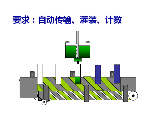
TSTS7300_08中文资料
S7300培训PPT132页
用钥匙开关执行存储器复位的方法:
1、合上电源开关
2、把钥匙开关转到STOP位置
3、把钥匙开关转到MRES位置(存储器复位)并保持 在这个位置直到STOP指示灯慢闪两次(约3秒)
问题四、S7-300的CPU模块
S7-300有20种不同型号的CPU,分别适用于不同等级 的控制要求。有的CPU集成了数字量I/O,有的同时集 成了数字量I/O和模拟量I/O。
CPU模块面板上有状态和故障指示灯LED、模式选择开 关和通信接口。大多数CPU还有后备电池盒,存储器 插槽可以插入多达数兆字节的Flash EPROM微存储器 卡(简称MMC卡),用于掉电后程序和数据的保存。
7、通讯处理器(CP)
扩展中央处理单元的通讯任务,提供以下的连网能力: -点到点连接 -PROFIBUS -工业以太网
8、附件
总线连接器和前连接器
七、S7-300的系统结构
S7-300采用紧凑的、无槽位限制的模块结构,电源模块 (PS)、CPU、信号模块(SM)、功能模块(FM)、接口模 块(IM)和通信处理器(CP)都安装在导轨上。导轨是一种 专用的金属机架,只需将模块钩在DIN标准的安装导轨上, 然后用螺栓锁紧就可以了。有多种不同长度规格的导轨供用 户选择。
十、存储器
存储器分为系统程序存储器和用户程序存储器。 系统程序相当于个人计算机的操作系统,由PLC生 产厂家设计并固化在ROM(只读存储器)中,用户 不能读取。用户程序由用户设计,它使PLC能完成 用户要求的特定功能。用户程序存储器的容量以 字(16位二进制数)为单位。
s7300使用说明书
一、S7-300初始化尽量使用window2000,Windows XP。
STEP7V52或以上版本1.2 通信1、设置通信`设置或添加PC Adapter(MPI), Property 按钮Local Connection 属性页COM 1 19200,注意一般连接到计算机的串行口1。
其他参数不需要设置,注意选择PC Adapter,不要有其他的,例如pc/ppi。
1.3 硬件组态2、新建工程在SIMATIC Manager中新建工程,也可以通过wizard向导建立。
选中右边的工程名,Insert Station SIMATIC 300。
双击Hardware,从而进入HW CONFIG窗口。
Option>Insert NEW GSE文件。
把MM420, ET200等GSD文件加入。
在hw config,如图所示,插入RAC-300机架。
选中机架第二栏,双击CPU-300>CPU313C-2DP,注意准确的编号。
默认地址2。
双击DP,选择Property按钮。
选择NEW,选择1.5MBPS,如果出现警告,可以选择187kpbs。
依次在SLOT 1,2,3位置插入其他模块。
0 电源模块S7-300DI 地址:256-263DO 地址:256-259选中DP线,然后双击ET200S,如图所示,插入ET200S.选择,依次在SLOT 1,2,3位置插入其他模块。
6ES7 138-4CA00-0AA0 PM-E DC24V6ES7 134-4GB50-0AB0 2AI I 2DMU地址I address264-2676ES7 134-4JB50-0AB0 2AI RTD地址I address268-271插入MM420选择4PKW, 2PZD (PPO1)2AX地址I address 280-283 Q address 268-271全部保存1.4 下装硬件组态并检测在SIMATIC Manager中,选择工程,选择PLC>Clear/Reset,可以清除原来的配置信息。
S7300常用操作说明.doc
实用标准文档利用 STEP7 监视输入输出量的方法DP:高速数据传送1、打开 PLC 软件。
运行 STEP7,打开 PLC 软件,将左侧的文件夹层层展开直到选中Blocks ,如下图所示:2、找到 VAT 块。
在右侧找到VAT_ ??的块,双击打开。
一般此块排列在所有块的最后面,名称以VAT 开头,后跟的下划线后的名称可能不一样,可以不管,如有不止一个,可以任意打开一个。
如下图:3、插入 VAT 块。
如没有找到此块,可以在自行添加一个,操作如下图,在右侧窗口空白处点击鼠标右键,选择 Insert New Object( 插入新对象 )—— Variable Table(变量表 )4、选中后将出现如下窗口5、打开 VAT 块。
点击 OK 按钮即可生成VAT_1 块。
打开 VAT 块,如下图:在 Address 一列中输入想要监视的地址,如需要监视第一流自动转换开关状态,则察看接口表7、监视数字量输入点。
如上图,察看接口表得知,第一流转换开关的自动档输入点为I0.0 ,第二流转换开关的自动档输入点为 I4.0 。
将这两个地址输入到VAT 窗口中的Address 一栏中,如图:在第一行中输入I0.0 后,回车后,光标自动移到第二行,第三列的Display format自动设为BOOL 类型。
在保证工控机与PLC 联接正常的情况下,可以点上图方框所示的Monitor Variable 按钮,则情况应如下图所示,窗口的标题栏变为高亮的青色,窗口右下角的RUN 状态栏有绿色状态条不断闪动。
下图所示的监视结果,I0.0 结果为绿色, true, I0.4 结果为灰色, false,表明第一流转换开关处于手动档,第二流转换开关不处于手动档。
9、错误判断。
如在 Address 栏中输入要监视的量后字变为红色,说明输入有误,例如:10、修改显示格式。
所有的数字量输入输出点的数据类型都是BOOL 型,即输入要监视的点后,使用系统给出的默认Display format (显示格式)BOOL 就可以了,如要监视模拟量输入点(模拟量输出点无法用VAT 监视),应该将显示格式改为Decimal 如下图所示,如需要监视第一流的液位采样输入点,看接口表得知,此点地址为386,则在 VAT 窗口的 Address(地址)一栏中输入PIW386 ,在 Display format 一栏中点右键,选择Decimal :11、监视模拟量输入。
第一讲__S7300简介资料.
革新型CPU(五种): CPU 312(新型) CPU 314 (新型) CPU 315-2DP(新型 )
CPU 317-2DP CPU 318-2DP
户外型CPU(三种): CPU 312 IFM CPU 314 IFM CPU 314(户外型)
故障安全型CPU(三种):
CPU 315F
CPU 315F-2DP
CPU
317F-2DP
ห้องสมุดไป่ตู้
特种型CPU(两种): CPU 317T-2DP CPU 317-2PN/DP
2、S7-300CPU的主要特性:
3、S7-300 CPU的操作:
RUN-P:可编程运行模式。在此模式下,CPU不仅可以执 行用户程序,在运行的同时,还可以通过编程设备(如装有 STEP 7的PG、装有STEP 7的计算机等)读 出、修改、监控用户程序。
信号模块的 前连接器
24V DC连接 器
CPU工作模 式选择开关
(CP后多U备点M31P电接3I以池口上)
前门
二、S7-300 CPU模块
1、CPU的分类 ➢紧凑型CPU(6种) ➢标准型CPU(5种) ➢革新型CPU(5种) ➢户外型CPU(3种) ➢故障安全型CPU(3种) ➢特种型CPU(2种)
IM 360
X2 34
360 - 3CA01- 0AA0
X2 34
360 - 3CA01- 0AA0
5、通信处理模块(CP)
➢ CP341:用于点对点连接的通讯模板
➢ CP343-1:用于连接工业以太网的通讯模板
MRES:存储器复位模式。该位置不能
保持,当开关在此位置释放时将自动返回
S7300模块简介CN
CPUS7-300/300C系列 CPU单元S7-300模块化微型PLC 系统,满足中、小规模的性能要求各种性能的模块可以非常好地满足和适应自动化控制任务简单实用的分布式结构和多界面网络能力,使得应用十分灵活方便用户和简易的无风扇设计当控制任务增加时,可自由扩展大量的集成功能使它功能非常强劲SIPLUS S7-300用于恶劣环境条件下的PLC扩展温度范围从-25°C 到+70°C适用于特殊的环境(污染空气中使用)允许短时冷凝以及短时机械负载的增加S7-300 采用经过认证的PLC 技术易于操作、编程、维护和服务特别适用于汽车工业、环境技术、采矿、化工厂、生产技术以及食品加工等领域低成本的解决方案S7-300紧凑型CPUCPU 312CCPU 313CCPU 313C-2 PtPCPU 313C-2 DPCPU 314C-2 PtPCPU 314C-2 DP标准型CPUCPU 312CPU 314CPU 315-2 DPCPU 315-2 PN/DPCPU 317-2 DPCPU 317-2 PN/DPCPU 319-3 PN/DPTechnology CPUIM 174SIMATIC S7-Technology SoftwareCPU 315T-2 DPCPU 317T-2 DP故障安全型CPUCPU 315F-2 DPCPU 315F-2 PN/DPCPU 317F-2 DPCPU 317F-2 PN/DPSIPLUS S7-300:(环境温度范围-25- +70°C;允许安装和运行于有害的气体环境;有电子成分涂层)SIPLUS 紧凑型CPUSIPLUS CPU 312CSIPLUS CPU 313CSIPLUS CPU 313C-2 DPSIPLUS CPU 314C-2 DPSIPLUS 标准型CPUSIPLUS CPU 314SIPLUS CPU 315-2DPSIPLUS CPU 315-2PN/DPSIPLUS CPU317-2PN/DPSIPLUS 故障安全型CPUSIPLUS S7-300 CPU 315F-2DPSIPLUS S7-300 CPU 317F-2DP以下CPU 运行均需要微存储卡CPU 312 适用于全集成自动化(TIA)的基本型CPU适用于中等处理速度要求的小规模应用CPU 312C 带集成数字量输入和输出的紧凑型CPU适用于对处理能力有较高要求的小型应用带有与过程相关的功能CPU 313C 带集成数字量和模拟量输入/ 输出的紧凑型CPU满足对处理能力和响应时间要求较高的场合带有与过程相关的功能CPU 313C-2 PtP 带集成数字量输入/ 输出和一个RS 422/485 串口的紧凑型CPU 满足处理量大、响应时间高的场合带有与过程相关的功能CPU 313C-2 DP 带集成数字量输入/ 输出和PROFIBUS DP 主站/ 从站接口的紧凑型CPU带有与过程相关的功能可以完成具有特殊功能的任务可以连接单独的I/O 设备CPU 314 适用于中等程序处理量的应用对二进制和浮点数运算具有较高的处理能力CPU 314C-2 PtP 带集成数字量和模拟量I/O和一个RS 422/485串口的紧凑型CPU满足对处理能力和响应时间要求较高的场合带有与过程相关的功能CPU 314C-2 DP 带集成数字量和模拟量I/O 以及PROFIBUS DP 主站/ 从站接口的紧凑型CPU带有与过程相关的功能可以完成具有特殊功能的任务可以连接单独的I/O 设备CPU 315-2 DP 具有中、大规模的程序存储容量和数据结构,如果需要,可以供SIMATIC 功能工具使用对二进制和浮点数运算具有较高的处理能力PROFIBUS DP 主站/ 从站接口可用于大规模的I/O 配置可用于建立分布式I/O 结构CPU 315-2 PN/DP 具有中等规模的程序存储容量和程序框架对二进制和浮点数运算具有较高的处理能力与集中式I/O 和分布式I/O 一起使用,可用作生产线上的中央控制器集成的PROFINET 接口组合了MPI/PROFIBUS DP- 主/ 从接口在PROFINET 上实现基于组件的自动化PROFINET代理,用于基于组件的自动化(CBA)中的PROFIBUS DP 智能设备PROFINET I/O 控制器,用于在PROFINET 上运行分布式I/OCPU 317-2 DP 具有大容量程序存储器,可用于要求很高的应用能满足标准机床、特殊机床以及车间应用的多任务自动化系统与集中式I/O 和分布式I/O 一起,可用作生产线上的中央控制器对二进制和浮点数运算具有较高的处理能力PROFIBUS DP 主站/ 从站接口可用于大规模的I/O 配置可用于建立分布式I/O 结构可以选用SIMATIC 工程工具在基于组件的自动化中实现分布式智能系统CPU 317-2 PN/DP 具有大容量程序存储器,可用于要求很高的应用在PROFINET 上实现基于组件的自动化中实现分布式智能系统PROFINET 代理,用于基于部件的自动(CBA)中的 PROFIBUS DP 智能设备PROFINET I/O 控制器,用于在PROFINET 上运行分布式I/O能满足标准机床、特殊机床以及车间应用的多任务自动化系统与集中式I/O 和分布式I/O 一起,可用作生产线上的中央控制器可用于大规模的I/O 配置可用于建立分布式I/O 结构对二进制和浮点数运算具有较高的处理能力组合了MPI/PROFIBUS DP 主/ 从接口可以选用SIMATIC 工程工具CPU 319-3 PN/DP 具有智能技术/运动控制功能的SIMATIC CPU新的S7-300 标准型CPU 319-3 PN/DP 开始接受订单CPU319-3 PN/DP 拓展了SIMATIC S7-300 CPU系列的产品线,是S7-300 系列性能最高的 CPU319-3 PN/DP 集成了3 个通讯接口1 个 MPI/PROFIBUS DP 的共用接口1 个纯 PROFIBUS DP 接口1 个 PROFINET 接口除了具有高性能,该CPU 还提供了以下新功能:PROFIBUS 接口的时钟同步,可连接256 个I/O 设备,扩展开放通讯CPU 315F-2 DP 可组态为一个故障安全型自动化系统,可满足安全运行的需要基于 SIMATIC CPU 315-2 DP带2 个接口(1x MPI, 1x DP/MPI)安全性满足 SIL 3(IEC 61508)、AK6(DIN V 19250)和Cat. 4(EN 954-1)不需要对安全相关I/O 进行额外接线使用带有PROFISAFE 协议的PROFIBUS DP 可实现与安全相关的通讯可以与故障安全型ET200S PROFISAFE I/O 模块进行分布式连接;可以与故障安全型 ET200M I/O 模块进行集中式和分布式连接标准模块的集中式和分布式使用,可满足于故障安全无关的应用CPU 315F-2 PN/DP 可组态为一个故障安全型自动化系统,以提高安全运行的需要安全性满足 SIL 3 (IEC 61508)和Cat. 4 (EN 954-1)可通过集成的PROFINET接口(PROFIsafe)和/ 或集成的PROFIBUS DP 接口(PROFIsafe)连接分布式站中的故障安全 I/O 模块可以与ET 200M 的故障安全型I/O 模块进行集中式连接;标准模块的集中式和分布式使用,可满足于故障安全无关的应用在PROFINET 上实现基于组件的自动化PROFINET 代理,用于基于部件的自动化(CBA)中的 PROFIBUS DP 智能设备CPU 317F-2 DP 可以组态为一个故障安全型自动化系统,可满足安全运行的需要安全性满足 SIL 3(IEC 61508)、AK6(DIN V 19250)和Cat. 4(EN 954-1)不需要对故障安全I/O 进行额外接线1 个 PROFIBUS DP 主/ 从接口和1 个DP 主/ 从/MPI 接口两个接口可用于集成故障安全模块故障安全ET200S PROFIsafe I/O 模块可以进行分布式连接可以与故障安全型 ET200M I/O 模块进行集中式和分布式连接标准模块的集中式和分布式使用,可满足于故障安全无关的应用CPU 317F-2 PN/DP 故障安全型CPU,具有大容量程序存储器和程序框架可组态为一个故障安全型自动化系统,以提高安全运行的需要安全性满足 SIL 3 (IEC 61508)和Cat. 4 (EN 954-1)可通过集成的PROFINET接口(PROFIsafe)和/ 或集成的PROFIBUS DP 接口(PROFIsafe)连接分布式站中的故障安全 I/O 模块可以与ET 200M 的故障安全型I/O 模块进行集中式连接;标准模块的集中式和分布式使用,可满足于故障安全无关的应用在PROFINET 上实现基于组件的自动化PROFINET 代理,用于基于部件的自动化(CBA)中的 PROFIBUS DP 智能设备CPU 315T-2 DP 具有智能技术/ 运动控制功能的SIMATIC CPU具有标准CPU 315-2 DP 的全部功能能满足系列化机床、特殊机床以及车间应用的多任务自动化系统最佳用于同步运动顺序,例如与虚拟/ 实际主设备的耦合、电子减速箱、凸轮盘或印刷点修正与集中式I/O 和分布式I/O 一起,可用作生产线上的中央控制器带有内只I/O,可实现快速技术功能(例如凸轮切换,参考点检测)PROFIBUS DP(DRIVE)接口,用来实现驱动部件的等时连接控制任务和运动控制任务使用相同的S7 应用程序(无需其它编程语言就可以实现运动控制)需要“S7 Technology”软件包CPU 317T-2 DP 具有智能技术/ 运动控制功能的SIMATIC CPU具有标准CPU 317-2 DP 的全部功能能满足系列化机床、特殊机床以及车间应用的多任务自动化系统最佳用于同步运动顺序,例如与虚拟/ 实际主设备的耦合、电子减速箱、凸轮盘或印刷点修正与集中式I/O 和分布式I/O 一起,可用作生产线上的中央控制器在PROFIBUS DP 上实现基于组件的自动化中实现分布式智能系统带有本机I/O,可实现快速技术功能(例如凸轮切换,参考点检测)PROFIBUS DP(DRIVE)接口,用来实现驱动部件的等时连接控制任务和运动控制任务使用相同的S7 应用程序(无需其它编程语言就可以实现运动控制)需要“S7 Technology”软件包SIPLUS CPU 312C 带集成数字量输入和输出的紧凑型CPU适用于对处理能力有较高要求的小型应用带有与过程相关的功能SIPLUS CPU 314 适用于中等程序处理量的应用对二进制和浮点数运算具有较高的处理能力SIPLUS CPU 313C 带集成数字量和模拟量输入/ 输出的紧凑型CPU满足处理量大、响应时间快的场合带有与过程相关的功能SIPLUS CPU 315-2DP 具有中、大规模的程序存储容量和数据结构,如果需要可以供SIMATIC 功能工具使用对二进制和浮点数运算具有较高的处理能力PROFIBUS DP 主站/ 从站接口可用于大规模的I/O 配置可用于建立分布式I/O 结构数字量输入/输出模块SIMATIC S7-300 的数字输入/输出模块使控制器灵活地与任务相适应用于连接数字传感器和执行元件数字量输入模块技术数据SM 321,16点输入,24V DCSM 321,16点输入,24V DC,低态有效SM 321,32点输入,24V DCSM 321,16点输入,24-48V DCSM 321,16点输入,48-125V DCSM 321,16点输入,24V DC,用于等时线模式下运行SM 321,32点输入,120V ACSM 321,8点输入,120/230V ACSM 321,8点输入,120/230V AC,与公共电位单独连接SM 321,16点输入,120/230V ACSM 321,16点输入,24V DC,用于等时线模式下运行,有诊断能力数字量输出模块SM 322,8点输出,24V DC,2ASM 322,16点输出,24V DC,0.5ASM 322,16点输出,24V DC,0.5A,高速SM 322,32点输出,24V DC,0.5ASM 322,8点输出,24V DC,0.5A,有诊断能力SM 322,16点输出,24/48V DC,0.5ASM 322,8点输出,48-125V DC,1.5ASM 322,8点输出,120/230V AC,1ASM 322,8点输出,120/230V AC,2ASM 322,16点输出,120/230V AC,1ASM 322,32点输出,120V AC,1ASM 322,8点输出,继电器,2ASM 322,8点输出,继电器,5ASM 322,8点输出,继电器,5A,RC滤波,过压保护SM 322,16点输出,继电器,8A数字量输入/输出模块SM 323,8点输入,8点输出SM 323,16点输入,16点输出SM 327,8点输入+ 8点输入或输出(可设置)SIPLUS数字量输入/输出模块SIPLUS SM 321,输入模块SIPLUS SM 322,输出模块SIPLUS SM 323,输入/输出模块模拟量输入/输出模块S7-300的模拟输入/输出模块用于完成包含模拟过程信号的较复杂任务用于连接不带附加放大器的模拟执行元件和传感器模拟量输入模块SM 331,8输入,13位分辨率SM 331,8输入,9/12/14位分辨率SM 331,2输入,9/12/14位分辨率SM 331,8输入,增强型16位分辨率SM 331,8输入,增强型16位分辨率,4通道模式SM 331,8输入,14位分辨率,用于等时线模式SM 331,8输入,用于热电阻,符合GOST标准SM 331,8输入,用于热电偶,符合GOST标准模拟量输出模块SM 332,4输出SM 332,4输出,15位SM 332,2输出SM 332,8输出模拟量输入/输出模块,SM335,U/ISM335,中断,诊断功能;4输入,4输出,14位分辨率,11/12位SIPLUS模拟量输入/输出模块SIPLUS SM 331 输入模块SIPLUS SM 332 输出模块SIPLUS SM 334 输入/输出模块功能模块功能模块技术数据新:PROFIBUS 模块 IM 174 详细-->FM 350-2计数器模块,8通道,最大20kHz;用于24V增量式编码器和NAMUR传感器FM 351定位模块,用于快速移动和慢速驱动FM 352电子凸轮控制器FM 352-5高速布尔处理器,带M切换的数字量输出FM 352-5高速布尔处理器,带P切换的数字量输出FM 352-5组态软件FM 355 C闭环控制模块,4模拟输出,4连续动作控制器FM 355 S闭环控制器模块,8数字输出,4步进或脉冲控制器FM 355-2 C温度控制器模块,4模拟输出,4连续动作控制器FM 355-2 S温度控制器模块,8数字量输出,4步进或脉冲控制器SM 338 POS输入模块,用带起/停接口的超声波传感器进行位置检测SM 338 POS输入模块,用于带起/停接口的超声波编码器通讯模块通讯CP 340通讯处理器,带一个RS232C(V.24)接口CP 341通讯处理器,带一个RS232C(V.24)接口CP 341通讯处理器,带一个20 MA(TTY)接口CP 341通讯处理器,带一个RS422/485接口CP 343-2,AS-InterfaceCP 343-2 P,AS-InterfaceCP 342-5,与PROFIBUS的电气接口CP 342-5 FO,与PROFIBUS的光学接口CP 343-5,与PROFIBUS, FMS, S7/PG/OP通信CP 343-1 Lean,通过TCP/IP和UDPCP 343-1,通过TCP/IP和UDPCP 343-1 IT,以太网,FTP, e-mail and WWW 服务器通讯CP343-1 PN,PROFInet, TCP/IP通讯存储卡存储卡MMC 64 KBMMC 128 KBMMC 512 KBMMC 2 MBMMC 4 MBMMC 8 MB接口模块接口模块IM 360,最多3个扩展单元;插入中央控制器IM361,最多3个扩展单元;插入扩展单元电源模块电源PS 307, 120/230 V AC; 24 V DC, 2 APS 307, 120/230 V AC; 24 V DC, 5 APS 307, 120/230 V AC; 24 V DC, 10 A附件配置订货数据速查表-->DIN 导轨概述SIMATIC S7-300的机械安装架用于安装调试可用螺丝紧固在墙上结构DIN 导轨是金属导轨,上面有用来安装螺丝的孔。
s7300操作规程
s7300操作规程S7300操作规程1. 安全操作1.1 操作人员应熟悉并理解S7300的操作手册和相关安全规定。
1.2 操作人员必须穿戴符合安全要求的个人保护装备,如安全鞋、安全帽等。
1.3 操作前应确保S7300处于停止状态,并断开电源。
1.4 操作人员应对S7300进行定期维护和检查,确保其正常工作并安全可靠。
2. 操作准备2.1 操作人员应具备一定的机电知识和经验,了解S7300的工作原理以及基本操作方法。
2.2 在操作S7300之前,应对任务进行充分的计划和准备,包括确定操作目标、了解操作步骤和相关安全措施等。
2.3 在操作S7300之前,应对操作台及其周围环境进行清理和整理,确保工作区域干净整洁,无杂物。
3. 启动和停止操作3.1 启动操作前,应确保必要的预处理已完成。
如检查S7300的电源和电缆连接是否正常、检查冷却系统是否工作正常等。
3.2 启动操作时,应按照操作手册的要求依次进行操作,确保各个环节顺利进行。
3.3 在S7300正常工作期间,操作人员应时刻保持警惕,密切关注设备运行状态,及时发现和处理异常情况。
3.4 停止操作时,应按照操作手册的要求依次进行操作,确保设备安全停止运行。
4. 维护和检修4.1 维护和检修工作必须由经过培训并合格的人员进行。
4.2 维护和检修前,应先切断S7300的电源,并进行必要的安全措施,如标识警示牌、锁定开关等。
4.3 维护和检修期间,应按照相关规定使用专用工具和仪器,严禁将非标准工具用于维护和检修工作。
4.4 维护和检修结束后,应恢复设备至正常状态,并清理维护和检修过程中产生的杂物和工具。
5. 应急措施5.1 在S7300发生故障、异常或危险情况时,应立即停止操作,并按照应急程序进行处理。
5.2 在应急处理过程中,应保持冷静,并按照预定的程序进行操作,确保人员安全和设备不受损害。
总结:S7300操作规程的关键是安全操作和准确操作。
操作人员应具备机电知识和经验,严格按照操作手册的要求进行操作。
LMP7300_08资料
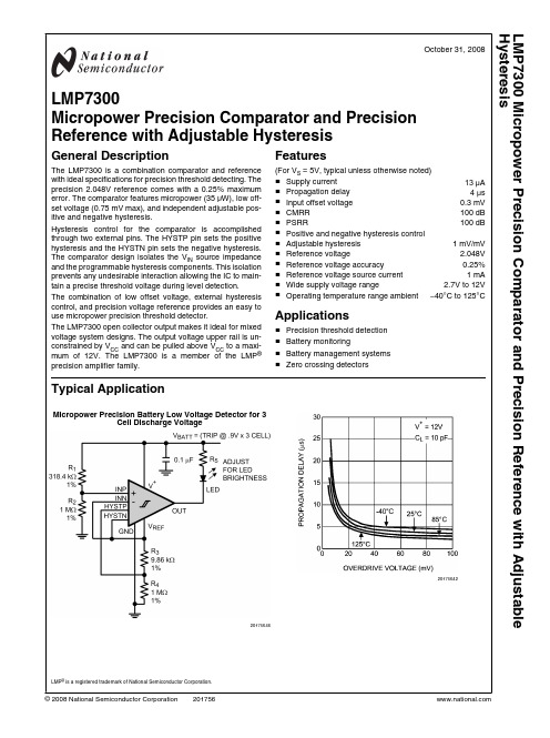
October 31, 2008LMP7300Micropower Precision Comparator and Precision Reference with Adjustable HysteresisGeneral DescriptionThe LMP7300 is a combination comparator and reference with ideal specifications for precision threshold detecting. The precision 2.048V reference comes with a 0.25% maximum error. The comparator features micropower (35 µW), low off-set voltage (0.75 mV max), and independent adjustable pos-itive and negative hysteresis.Hysteresis control for the comparator is accomplished through two external pins. The HYSTP pin sets the positive hysteresis and the HYSTN pin sets the negative hysteresis.The comparator design isolates the V IN source impedance and the programmable hysteresis components. This isolation prevents any undesirable interaction allowing the IC to main-tain a precise threshold voltage during level detection.The combination of low offset voltage, external hysteresis control, and precision voltage reference provides an easy to use micropower precision threshold detector.The LMP7300 open collector output makes it ideal for mixed voltage system designs. The output voltage upper rail is un-constrained by V CC and can be pulled above V CC to a maxi-mum of 12V. The LMP7300 is a member of the LMP ®precision amplifier family.Features(For V S = 5V, typical unless otherwise noted)■Supply current13 μA ■Propagation delay4 μs ■Input offset voltage 0.3 mV ■CMRR100 dB ■PSRR100 dB ■Positive and negative hysteresis control■Adjustable hysteresis1 mV/mV ■Reference voltage2.048V ■Reference voltage accuracy0.25%■Reference voltage source current1 mA ■Wide supply voltage range2.7V to 12V ■Operating temperature range ambient −40°C to 125°CApplications■Precision threshold detection ■Battery monitoring■Battery management systems ■Zero crossing detectorsTypical ApplicationMicropower Precision Battery Low Voltage Detector for 3Cell Discharge Voltage2017564620175642LMP ® is a registered trademark of National Semiconductor Corporation.© 2008 National Semiconductor Corporation LMP7300 Micropower Precision Comparator and Precision Reference with Adjustable HysteresisAbsolute Maximum Ratings (Note 1)If Military/Aerospace specified devices are required,please contact the National Semiconductor Sales Office/Distributors for availability and specifications.ESD Tolerance (Note 2) Human Body Model 2000V Machine Model200V V IN Differential±V SSupply Voltage (V S = V + – V −)13.6VVoltage at Input/Output Pins V + + 0.3V, V − − 0.3VStorage Temperature Range−65°C to +150°CJunction Temperature (Note 3)+150°C Soldering Information Infrared or Convection (20 sec)235°C Wave Soldering Lead Temp. (10 sec)260°COperating Ratings(Note 1)Temperature Range (Note 3)−40°C to 125°CSupply Voltage (V S = V + – V −)2.7V to 12VPackage Thermal Resistance (θJA (Note 3)) 8-Pin SOIC 166°C/W 8-Pin MSOP235°C/W2.7V Electrical Characteristics(Note 4)Unless otherwise specified, all limits are guaranteed for T A = 25°C, V + = 2.7V, V − = 0V, and V CM = V +/2, R PULLUP = 100 k Ω,C LOAD = 10 pF. Boldface limits apply at the temperature extremes.Symbol ParameterConditionsMin (Note 6)Typ (Note 5)Max (Note 6)UnitsI SSupply CurrentR PULLUP = Open91217μAComparator V OS Input Offset Voltage V CM = V +/2 ±0.07±0.75±2mV TCV OS Input Offset Average Drift (Note 8) 1.8 μV/°C I B Input Bias Current (Note 7)|V ID | < 2.5V 1.234nA I OS Input Offset Current0.150.5nA CMRR Common Mode Rejection Ratio 1V < V CM < 2.7V 80100 dB PSRR Power Supply Rejection Ratio V + = 2.7V to 12V 80100 dB V OL Output Low Voltage I LOAD = 10 mA0.250.40.5V I LEAK Output Leakage Current Comparator Output in High State 1 pA HC LIN Hysteresis Control Voltage Linearity0 < Ref-H YS TP,N < 25 mV 1.000 mV/V 25 mV < Ref-H YS TP,N < 100 mV 0.950 I HYS Hysteresis Leakage Current1.234nA T PDPropagation Delay (High to Low)Overdrive = 10 mV, C L = 10 pF 1217μsOverdrive = 100 mV, C L = 10 pF4.57.6Reference V O Reference Voltage2.043 2.048 2.053V Line Regulation V CC = 2.7V to 12V 1480μV/V Load Regulation I OUT = 0 to 1 mA 0.20.5mV/mA TCV REF/°C Temperature Coefficient−40°C to 125°C 55ppm/°C V NOutput Noise Voltage0.1 Hz to 10 Hz 80 μV PP 10 Hz to 10 kHz100μV RMS 2L M P 73005V Electrical Characteristics(Note 4)Unless otherwise specified, all limits are guaranteed for T A = 25°C, V + = 5V, V − = 0V, and V CM = V +/2, R PULLUP = 100 k Ω, C LOAD =10 pF. Boldface limits apply at the temperature extremes.Symbol ParameterConditionsMin (Note 6)Typ (Note 5)Max (Note 6)UnitsI SSupply CurrentR PULLUP = Open101318μAComparator V OS Input Offset Voltage V CM = V +/2 ±0.07±0.75±2mV TCV OS Input Offset Average Drift (Note 8) 1.8 μV/°C I B Input Bias Current (Note 7)|V ID | < 2.5V 1.234nA I OS Input Offset Current0.150.5nA CMRR Common Mode Rejection Ratio 1 ≤ V CM ≤ 5V 80100 dB PSRR Power Supply Rejection Ratio V + = 2.7V to 12V 80100 dB V OL Output Voltage Low I LOAD = 10 mA0.250.4V I LEAK Output Leakage Current Comparator Output in High State 1 pA HC LIN Hysteresis Control Voltage Linearity0 < Ref-V HYS TP,N < 25 mV 1.000 mV/V 25 mV < Ref-V HYS TP,N < 100 mV 0.950 I HYS Hysteresis Leakage Current1.234nA TPD Propagation Delay (High to Low)Overdrive = 10 mV, C L = 10 pF 1215μsOverdrive = 100 mV, C L = 10 pF47Reference V O Reference Voltage2.043 2.048 2.053V Line Regulation V CC = 2.7V to 12V 1480μV/VLoad Regulation I OUT = 0 to 1 mA 0.20.5mV/mA TCV REF/°C Temperature Coefficient −40°C to 125°C 55ppm/°C V NOutput Noise Voltage0.1 Hz to 10 Hz 80 μV PP 10 Hz to 10 kHz100μV RMS12V Electrical Characteristics(Note 4)Unless otherwise specified, all limits are guaranteed for T A = 25°C, V + = 12V, V − = 0V, and V CM = V +/2, R PULLUP = 100 k Ω,C LOAD = 10 pF. Boldface limits apply at the temperature extremes.Symbol ParameterConditionsMin (Note 6)Typ (Note 5)Max (Note 6)UnitsI SSupply CurrentR PULLUP = Open111420µAComparator V OS Input Offset Voltage V CM = V +/2 ±0.08±0.75±2mV TCV OS Input Offset Average Drift (Note 8) 1.8 μV/°C I B Input Bias Current (Note 7)|V ID | > 2.5V 1.234nA I OS Input Offset Current0.150.5nA CMRR Common Mode Rejection Ratio 1V ≤ V CM ≤ 12V 80100 dB PSRR Power Supply Rejection Ratio V + = 2.7V to 12V 80100 dB V OL Output Voltage Low I LOAD = 10 mA0.250.4V I LEAKOutput Leakage CurrentComparator Output in High State1pALMP7300Symbol ParameterConditionsMin (Note 6)Typ (Note 5)Max (Note 6)UnitsHC LIN Hysteresis Control Voltage Linearity0 < Ref-V +HYS TP,N < 25 mV 1.000 mV/V 25 mV < Ref-V +HYS TP,N < 100 mV 0.950 I HYS Hysteresis Leakage Current1.234nA TPD Propagation Delay (High to Low)Overdrive = 10 mV, C L = 10 pF 1115μsOverdrive = 100 mV, C L = 10 pF3.56.8Reference V O Reference Voltage T J = 25°C 2.043 2.048 2.053V Line Regulation V CC = 2.7V to 12V 1480μV/VLoad Regulation I OUT = 0 to 1 mA 0.20.5mV/mA TCV REF/°C Temperature Coefficient −40°C to +125°C 55ppm/°C V NOutput Noise Voltage0.1 Hz to 10 Hz 80 μV PP 10 Hz to 10 kHz100μV RMSNote 1:Absolute Maximum Ratings indicate limits beyond which damage to the device may occur. Operating Ratings indicate conditions for which the device is intended to be functional, but specific performance is not guaranteed. For guaranteed specifications and the test conditions, see the Electrical Characteristics Tables.Note 2:Human Body Model, applicable std. MIL-STD-883, Method 3015.7. Machine Model, applicable std. JESD22-A115-A (ESD MM std. of JEDEC)Field-Induced Charge-Device Model, applicable std. JESD22-C101-C (ESD FICDM std. of JEDEC).Note 3:The maximum power dissipation is a function of T J(MAX), θJA . The maximum allowable power dissipation at any ambient temperature is P D = (T J(MAX) – T A )/ θJA . All numbers apply for packages soldered directly onto a PC Board.Note 4:Electrical Table values apply only for factory testing conditions at the temperature indicated. Factory testing conditions result in very limited self-heating of the device such that T J = T A . No guarantee of parametric performance is indicated in the electrical tables under conditions of internal self-heating where T J >T A .Note 5:Typical values represent the most likely parametric norm as determined at the time of characterization. Actual typical values may vary over time and will also depend on the application and configuration. The typical values are not tested and are not guaranteed on shipped production material.Note 6:Limits are 100% production tested at 25°C. Limits over the operating temperature range are guaranteed through correlations using statistical quality control (SQC) method.Note 7:Positive current corresponds to current flowing into the device.Note 8:Offset voltage average drift determined by dividing the change in V OS at temperature extremes, by the total temperature change.Ordering InformationPackage Part Number Package Marking Transport Media NSC Drawing8-Pin SOIC LMP7300MA LMP7300MA95 Units/Rail M08A LMP7300MAX 2.5k Units Tape and Reel 8-Pin MSOPLMP7300MM C31A1k Units Tape and Reel MUA08ALMP7300MMX3.5k Units Tape and Reel 4L M P 7300Connection Diagram8-Pin MSOP/SOIC20175606Top ViewPin DescriptionsPinNameDescription+IN Non-InvertingComparator Input The +IN has a common-mode voltage range from 1V above the negative rail to, and including, the positive rail. Internal ESD diodes, connected from the +IN pin to the rails, protect the input stage from overvoltage. If the input voltage exceeds the rails, the diodes turn on and clamp the input to a safe level.−IN Inverting ComparatorInput The −IN has a common-mode voltage range from 1V above the negative rail to, and including, the positive rail. Internal ESD diodes, connected from the −IN pin to the rails, protects the input stage from overvoltage. If the input voltage exceeds the rails, the diodes turn on and clamp the input to a safe level.GND Ground This pin may be connected to a negative DC voltage source for applications requiring a dualsupply. If connected to a negative supply, decouple this pin with 0.1 µF ceramic capacitor toground. The internal reference output voltage is referenced to this pin. GND is the diesubstrate connection.OUT Comparator Output The output is an open-collector. It can drive voltage loads by using a pullup resistor, or it candrive current loads by sinking a maximum output current. This pin may be taken to amaximum of +12V with respect to the ground pin, irrespective of supply voltage.HYSTN Negative Hysteresis Pin This pin sets the lower trip voltage VIL. The common mode range is from 1V above thenegative rail to VCC . The input signal must fall below VILfor the comparator to switch fromhigh to low state.HYSTP Positive Hysteresis pin This pin sets the upper trip voltage VIH. The common mode range is from 1V above thenegative rail to VCC . The input signal must rise above VIHfor the comparator to switch fromlow to high state.REF Reference VoltageOutput PinThis is the output pin of a 2.048V band gap precision reference.V+Positive Supply Terminal The supply voltage range is 2.7V to 12V. Decouple this pin with 0.1 μF ceramic capacitor toground. LMP7300Typical Performance CharacteristicsSupply Current vs. Supply Voltage20175639Output Low Voltage vs. Load Current20175632Output Low Voltage vs. Load Current 20175633Output Low Voltage vs. Load Current20175634Reference Voltage vs. Supply Voltage 20175635Reference Voltage vs. Source Current20175636 6L M P 7300Reference Voltage vs. Sink Current20175637Reference Voltage vs. Source Current20175638Propagation Delay vs. Overdrive Voltage20175640Propagation Delay vs. Overdrive Voltage20175641Propagation Delay vs. Overdrive Voltage20175642 LMP7300Application InformationGENERAL DESCRIPTIONThe LMP7300 is a unique combination of micropower and precision. The open collector comparator has low offset, high CMRR, high PSRR, programmable hysteresis and microamp supply current. The precision 2.048V reference provides a DAC or ADC with an accurate binary divisible voltage. The comparator and reference combination forms an ideal single IC solution for low power sensor or portable applications.VOLTAGE REFERENCEThe reference output voltage is a band gap derived 2.048V that is trimmed to achieve typically 0.2% accuracy over the full operating temperature range of −40°C to 125°C. The trim procedure employs a curvature correction algorithm to com-pensate for the base emitter thermal nonlinearity inherent in band gap design topologies. The reference accuracy and the set resistor tolerance determine the magnitude and precision of the programmable hysteresis. In situations where refer-ence noise filtering is required a 5 µF capacitor in series with a 190Ω resistor to ground are PARATOROutput StageThe comparator employs an open collector output stage that can switch microamp loads for micropower precision thresh-old detection to applications requiring activating a solenoid, a lamp, or an LED. The wired-OR type output easily interfaces to TTL, CMOS, or multiple outputs, as in a window comparator application, over a range of 0.5V to 12V. The output is capable of driving greater than 10 mA output current and yet main-taining a saturation voltage below 0.4V over temperature. The supply current increases linearly when driving heavy loads so a pullup resistor of 100 k Ω or greater is recommended for mi-cropower applications.Fault Detection RateThe user’s choice of a pullup resistor and capacitive load de-termines the minimum response time and the event detection rate. By optimizing overdrive, the pullup resistor and ca-pactive load fault update rates of 200 kHz to 250 kHz or greater can be achieved.HYSTERESISF alse triggering on noise coupled into the signal path is a common problem for comparator based threshold detectors.One of the most effective solutions is to add hysteresis. Hys-teresis is a circuit signal path characteristic where an ampli-tude delay is introduced to the normal input. Positive hysteresis forces the signal to pass the normal switch point before the output makes a low to high transition while negative hysteresis does the opposite. This is a memory effect. The comparator behaves differently based on which direction the signal is going.The LM7300 has been designed with a unique way of intro-ducing hysteresis. The set points are completely independent of each other, the power supply, and the input or output con-ditions. The HYSTP pin sets positive hysteresis and the HYSTN pin sets the negative hysteresis in a simple way using two resistors. The pins can be tied together for the same hys-teresis or tied to separate voltage taps for asymmetric hys-teresis, or tied to the reference for no hysteresis. When the precision reference is used to drive the voltage tap resistor divider precise, stable threshold levels can be obtained. The maximum recommended hysteresis is about 130 mV. Thisplaces the HYSTP and HYSTN pin voltages at V REF – 130 mV which is approximately the center of their input common mode range at 2.7V. F or the typical example, a differential input signal voltage, V IN , is applied between INP and INN, the non-inverting and inverting inputs of the comparator. A DC switch or threshold voltage, V TH , is set on the negative input to keep the output off when the signal is above and on when it goes below this level. For a precision threshold tie the INN pin to V REF . With the output, off the circuit is in the minimum power state. Figure 1 through Figure 5 demonstrate the different configurations for setting the upper threshold V IH and the low-er threshold V IL and their relationship to the input trip point V REF , by the following formulas.20175607(a)20175608(b)When V ID = 0, INN = INP = V THFIGURE 1. Typical Micropower Application to SetAsymmetric Positive andNegative Hysteresis of −10 mV, +3 mV8L M P 7300Figure 2 shows the configuration with no hysteresis when theHYSTP and HYSTN pins are connected together to VREF.This configuration is not recommended because it has thehighest level of false triggers due to the system noise.20175611(a)20175609(b)FIGURE 2. Typical Configuration for No HysteresisFigure 3 shows the configuration with symmetric hysteresiswhen the HYSTP and HYSTN pins are connected to the samevoltage that is less than VREF. The two trip points set a hys-teresis band around the input threshold voltage VREF, suchthat the positive band is equal to the negative band.This configuration controls the false triggering mentioned inFigure 2. Symmetric hysteresis values less than 5 mV to 10mV are recommended for precise level detection applica-tions.20175614(a)20175612(b)FIGURE 3. Symmetric Hysteresis ±5 mVLMP7300Figure 4 shows the case for negative hysteresis by biasingonly the HYSN pin to a voltage less than VREF.20175618(a)20175616(b)FIGURE 4. Typical Configuration for Negative Hysteresis= −10 mVThe case for setting only a positive hysteresis is demonstrat-ed in Figure 5.20175622(a)20175620(b)FIGURE 5. Connections for Positive Hysteresis = +10 mV 10LMP73In the general case, as demonstrated with both positive and negative hysteresis bands in Figure 6, noise within these bands will have no affect on the state of the comparator out-put. In Example #1 the noise is well behaved and in band. The output is clean and well behaved. In Example #2, a significant amount of out of band noise is present but due to hysteresis no false triggers occur on the rising positive or falling negative edges. The hysteresis forces the signal level to move higher or lower before the output is set to the opposite state.20175628 FIGURE 6. Output Response with Input Noise Less thanHysteresis BandHow Much Hysteresis Is Correct?An effective way of determining the minimum hysteresis nec-essary for clean switching is to decrease the amount of hys-teresis until false triggering is observed, and then use a multiple of say three times that amount of hysteresis in the final circuit. This is most easily accomplished in the bread-board phase by making R1and R2potentiometers. For appli-cations near or above +100°C a minimum of 5 mV hysteresis is recommended due to peaking of the LMP7300 noise sen-sitivity at high temperatures.LAYOUT RECOMMENDATIONSA good PCB layout is always important to reduce output to input coupling. Positive feedback noise reduces performance. For the LMP7300 output coupling is minimized by the unique package pinout. The output is kept away from the non-invert-ing and inverting inputs, the reference and the hysteresis pins. EVALUATION BOARDSNational Semiconductor provides the following PCB boards as an aid in evaluating the LMP7300 performance.Device Package Evaluation BoardOrdering IDLMP7300MA8-Pin SOIC LMP7300MA-EVALLMP7300MM8-Pin MSOP LMP7300MM-EVAL WINDOW COMPARATORFigure 8 shows two LMP7300s configured as a micropower window detector in a temperature level detection application. The circuit shown monitors the ambient temperature change. If the temperature rises outside the 15°C to 35°C window, ei-ther comparator 1 for high temp, or comparator 2 for low temp, will set low, indicating a fault condition has occurred. The open collector outputs are pulled up separately but can be wire-OR’d for a single fault indication. If the temperature re-turns inside the window it must overcome the 22 mV asym-metric hysteresis band established on either comparator. For the high side the temperature must drop below 34°C and for the low side the temperature must rise above 16°C for the outputs to reset high and remove the fault indication. The temperature is sensed by a 30 kΩ @ 25°C Omega Precision NTC Thermistor #44008 (±0.2% tol).20175629FIGURE 7. Temperature Controlled Window Detector to Monitor Ambient Temperature LMP7300PRECISION HIGH TEMPERATURE SWITCHThe LMP7300 brings accuracy and stability to simple sensor switch applications. Figure 9 shows the LMP7300 setup in a high temperature switch configuration. The input bridge es-tablishes the trip point at 85°C and the reset temperature at 80°C. The comparator is set up with positive hysteresis of 14.3 mV and no negative hysteresis. When the temperature is rising it trips at 85°C. The 14.3 mV hysteresis allows the temperature to drop to 80°C before reset.The temperature sensor used is an Omega 44008 Precision NTC Thermistor. The 44008 has an accuracy of ±0.2°C. The resistance at 85°C is 3270.9Ω and at 80°C is 3840.2Ω. The trip voltage threshold is established by one half of the bridge,which is the ratio of R ADJ and R SET . The input signal bias is set by the second half, which is the ratio of the thermistor re-sistance R TH and R SET . The resistance values are chosen for ∼50 µA bridge current to minimize the power in the thermistor.The thermistor specification states it has a 1°C/mW dissipa-tion error. The reference voltage establishes the supply volt-age for the bridge to make the circuit independent of supply voltage variation. Capacitor C 1 establishes a low frequency pole at F CORNER = 1/(2πC 1*2(R SET //R ADJ )). With the resis-tance values chosen C 1 should be selected for Fc < 10 Hz.This will limit the thermal noise in the bridge.The accuracy of the circuit can be calculated from the nearest resistance values chosen. F or 1% resistors RADJ is 3.24k Ω, and R SET is 78.7 k Ω. The bridge gain becomes 2.488 mV/C at 85°C. In general, the higher the bridge current is allowed to be, the higher the bridge gain will be. The actual trip point found during simulation is 85.3°C and the reset point is 80.04°C. With the values chosen the worst case trip tem-perature uncertainty is ±1.451°C and the reset uncertainty is ±1.548°C. Accuracy could be maximized with resistors cho-sen to 0.1% values, 0.1% tolerance and by using the 0.1%model of the Omega 44008 thermistor.20175647FIGURE 8. Precision High Temperature SwitchMICROPOWER PRECISION BATTERY LOW VOLTAGE DETECTORThe ability of the LMP7300 to operate at very low supply volt-ages, makes it an ideal choice for low battery detection ap-plication in portable equipment. The circuit in Figure 9performs the function of low voltage threshold detection in a 3 cell 0.9V discharge voltage, battery monitor application.R 1 and R 2 are chosen to set the inverting input voltage equalto the non-inverting input voltage when the battery voltage is equal to the minimum operating voltage of the system. Here,the very precise reference output voltage is directly connect-ed to the non-inverting input on the comparator and sets an accurate threshold voltage. The hysteresis is set to 0 mV negative and 20 mV positive. The output is off for voltages higher than the minimum V BATT , and turns on when the circuit detects a minimum battery voltage condition.20175631FIGURE 9. Battery Voltage Monitor for 3 Cell Discharge Voltage 12L M P 7300Physical Dimensions inches (millimeters) unless otherwise noted8-Pin SOICNS Package Number M08A8-Pin MSOPNS Package Number MUA08A LMP7300NotesL M P 7300 M i c r o p o w e r P r e c i s i o n C o m p a r a t o r a n d P r e c i s i o n R e f e r e n c e w i t h A d j u s t a b l e H y s t e r e s i sFor more National Semiconductor product information and proven design tools, visit the following Web sites at:ProductsDesign SupportAmplifiers /amplifiers WEBENCH /webench Audio/audio Analog University /AU Clock Conditioners /timing App Notes /appnotes Data Converters /adc Distributors /contacts Displays /displays Green Compliance /quality/green Ethernet /ethernet Packaging/packaging Interface /interface Quality and Reliability /quality LVDS/lvds Reference Designs /refdesigns Power Management /power Feedback /feedback Switching Regulators /switchers LDOs /ldo LED Lighting /led PowerWise/powerwise Serial Digital Interface (SDI)/sdiTemperature Sensors /tempsensors Wireless (PLL/VCO)/wirelessTHE CONTENTS OF THIS DOCUMENT ARE PROVIDED IN CONNECTION WITH NATIONAL SEMICONDUCTOR CORPORATION (“NATIONAL”) PRODUCTS. NATIONAL MAKES NO REPRESENTATIONS OR WARRANTIES WITH RESPECT TO THE ACCURACY OR COMPLETENESS OF THE CONTENTS OF THIS PUBLICATION AND RESERVES THE RIGHT TO MAKE CHANGES TO SPECIF ICATIONS AND PRODUCT DESCRIPTIONS AT ANY TIME WITHOUT NOTICE. NO LICENSE, WHETHER EXPRESS,IMPLIED, ARISING BY ESTOPPEL OR OTHERWISE, TO ANY INTELLECTUAL PROPERTY RIGHTS IS GRANTED BY THIS DOCUMENT.TESTING AND OTHER QUALITY CONTROLS ARE USED TO THE EXTENT NATIONAL DEEMS NECESSARY TO SUPPORT NATIONAL’S PRODUCT WARRANTY. EXCEPT WHERE MANDATED BY GOVERNMENT REQUIREMENTS, TESTING OF ALL PARAMETERS OF EACH PRODUCT IS NOT NECESSARILY PERF ORMED. NATIONAL ASSUMES NO LIABILITY F OR APPLICATIONS ASSISTANCE OR BUYER PRODUCT DESIGN. BUYERS ARE RESPONSIBLE F OR THEIR PRODUCTS AND APPLICATIONS USING NATIONAL COMPONENTS. PRIOR TO USING OR DISTRIBUTING ANY PRODUCTS THAT INCLUDE NATIONAL COMPONENTS, BUYERS SHOULD PROVIDE ADEQUATE DESIGN, TESTING AND OPERATING SAFEGUARDS.EXCEPT AS PROVIDED IN NATIONAL’S TERMS AND CONDITIONS OF SALE FOR SUCH PRODUCTS, NATIONAL ASSUMES NO LIABILITY WHATSOEVER, AND NATIONAL DISCLAIMS ANY EXPRESS OR IMPLIED WARRANTY RELATING TO THE SALE AND/OR USE OF NATIONAL PRODUCTS INCLUDING LIABILITY OR WARRANTIES RELATING TO FITNESS FOR A PARTICULAR PURPOSE, MERCHANTABILITY, OR INF RINGEMENT OF ANY PATENT, COPYRIGHT OR OTHER INTELLECTUAL PROPERTY RIGHT.LIFE SUPPORT POLICYNATIONAL ’S PRODUCTS ARE NOT AUTHORIZED FOR USE AS CRITICAL COMPONENTS IN L IFE SUPPORT DEVICES OR SYSTEMS WITHOUT THE EXPRESS PRIOR WRITTEN APPROVAL OF THE CHIEF EXECUTIVE OFFICER AND GENERAL COUNSEL OF NATIONAL SEMICONDUCTOR CORPORATION. As used herein:Life support devices or systems are devices which (a) are intended for surgical implant into the body, or (b) support or sustain life and whose failure to perform when properly used in accordance with instructions for use provided in the labeling can be reasonably expected to result in a significant injury to the user. A critical component is any component in a life support device or system whose failure to perform can be reasonably expected to cause the failure of the life support device or system or to affect its safety or effectiveness.National Semiconductor and the National Semiconductor logo are registered trademarks of National Semiconductor Corporation. All other brand or product names may be trademarks or registered trademarks of their respective holders.Copyright© 2008 National Semiconductor CorporationFor the most current product information visit us at National Semiconductor Americas Technical Support CenterEmail: support@ Tel: 1-800-272-9959National Semiconductor Europe Technical Support CenterEmail: europe.support@ German Tel: +49 (0) 180 5010 771English Tel: +44 (0) 870 850 4288National Semiconductor Asia Pacific Technical Support Center Email: ap.support@National Semiconductor Japan Technical Support Center Email: jpn.feedback@。
S7300现场总线(智能从站)

主站通过CPU集成PROFIBUS-DP接口与智能从站通信一、实验目的1、掌握主站与智能从站通信组态方法和参数设置;2、用SFC14和SFC15进行数据交换编程。
二、实验设备1、PROFIBUS-DP一个主站S7-300 CPU315-2DP2、两个智能从站CPU315-2DP3、MPI网卡CP56114、PROFIBUS总线连接器及电缆5、计算机(带STEP7软件)三、实验内容建一主站CPU315-2DP(站地址为2),两个从站CPU315-2DP(站地址分别为3和4),设置主从通信的通信接口区,使主站与各从站进行通信。
四、实验操作步骤1、组态3号从站(1)、新建一项目,名称为智能从站。
在此项目之下插入一个S7300的从站,双击HARDWARE,进入“HW Config”窗口。
依次插入UR、PS、CPU等模块。
(2)、新建PROFIBUS(1)网络:在放入CPU模块的同时,如下图按要求新建一PROFIBUS(1)网络。
系统为CPU300定义的在网络上的节点为3; PROFIBUS(1)网络的属性设置在“Network setting”选项卡中设置。
(3)、设置从站通信接口区双击CPU315-2DP下“DP”项,在出现的PROFIBUS-DP属性菜单中设置①、在“工作模式”选项卡中选择“DP 从站”②、在“组态”选项卡中点击“新建”,新建一个输入通信接口区,为1个字节。
2、组态4号从站插入新的一个S7-300的站,硬件和网络组态和3号站相同,但站号为4,且输入通信接口区地址为40。
3、组态2号主站(1)、在同一项目之下插入一S7-300的主站,双击HARDWARE,进入“HW Config”窗口依次插入依次插入UR、PS、CPU模块。
(2)、在放入CPU模块的同时,选择PROFIBUS(1)网络。
设置网络上的节点为2;PROFIBUS(1)网络的属性设置在“Network setting”选项卡中设置。
S7300常用操作说明.doc

实用标准文档利用 STEP7 监视输入输出量的方法DP:高速数据传送1、打开 PLC 软件。
运行 STEP7,打开 PLC 软件,将左侧的文件夹层层展开直到选中Blocks ,如下图所示:2、找到 VAT 块。
在右侧找到VAT_ ??的块,双击打开。
一般此块排列在所有块的最后面,名称以VAT 开头,后跟的下划线后的名称可能不一样,可以不管,如有不止一个,可以任意打开一个。
如下图:3、插入 VAT 块。
如没有找到此块,可以在自行添加一个,操作如下图,在右侧窗口空白处点击鼠标右键,选择 Insert New Object( 插入新对象 )—— Variable Table(变量表 )4、选中后将出现如下窗口5、打开 VAT 块。
点击 OK 按钮即可生成VAT_1 块。
打开 VAT 块,如下图:在 Address 一列中输入想要监视的地址,如需要监视第一流自动转换开关状态,则察看接口表7、监视数字量输入点。
如上图,察看接口表得知,第一流转换开关的自动档输入点为I0.0 ,第二流转换开关的自动档输入点为 I4.0 。
将这两个地址输入到VAT 窗口中的Address 一栏中,如图:在第一行中输入I0.0 后,回车后,光标自动移到第二行,第三列的Display format自动设为BOOL 类型。
在保证工控机与PLC 联接正常的情况下,可以点上图方框所示的Monitor Variable 按钮,则情况应如下图所示,窗口的标题栏变为高亮的青色,窗口右下角的RUN 状态栏有绿色状态条不断闪动。
下图所示的监视结果,I0.0 结果为绿色, true, I0.4 结果为灰色, false,表明第一流转换开关处于手动档,第二流转换开关不处于手动档。
9、错误判断。
如在 Address 栏中输入要监视的量后字变为红色,说明输入有误,例如:10、修改显示格式。
所有的数字量输入输出点的数据类型都是BOOL 型,即输入要监视的点后,使用系统给出的默认Display format (显示格式)BOOL 就可以了,如要监视模拟量输入点(模拟量输出点无法用VAT 监视),应该将显示格式改为Decimal 如下图所示,如需要监视第一流的液位采样输入点,看接口表得知,此点地址为386,则在 VAT 窗口的 Address(地址)一栏中输入PIW386 ,在 Display format 一栏中点右键,选择Decimal :11、监视模拟量输入。
s7300概述

IM (可选)
SM: DI
SM: DO
SM: AI
SM: AO
FM: - 计数 - 定位 - 闭环控制
CP: - 点-到-点 - PROFIBUS - 工业以太网
PLC基本单元
~110V/220V市电 现场用户输入设备 现场信号 按钮、开关 传感器 外部设备 编程设备 计算机 打印机等 通 讯 及 编 程 接 口 系 统 存 储 器 用 户 存 储 器 I/O 扩 展 接 口 输 入 部 件 微处理器(CPU) 运算器 控制器 输 出 部 件 电源变换器 现场用户输出设备 执行器 中间继电器 电磁阀 扩展设备 扩展单元 通讯模块 功能模块
通讯处理器模版CP340 通讯处理器模版CP341 通讯处理器模版CP342-2/ CP343-2 通讯处理器模版CP342-5 通讯处理器模版CP343-1 通讯处理器模版CP343-1TCP 通讯处理器模版CP343-5
电源模版PS307将用于120/230V交流电压转换为24V直流电压,根 据输出电流的不同,有3种规格的电源模版可选:2A、5A、10A。
数字量输出模块SM322将S7-300内部信号电平转换成ቤተ መጻሕፍቲ ባይዱ程所要求
的外部信号电平,可直接用于驱动电磁阀、接触器、小型电动机、灯
和电动机启动器等。 晶体管输出模块只能带直流负载,属于直流输出模块;
可控硅输出方式属于交流输出模块;
继电器触点输出方式的模块属于交直流两用输出模块。 从响应速度上看,晶体管响应最快,继电器响应最慢;从安全隔离 效果及应用灵活性角度来看,以继电器触点输出型最佳。
PLC系统结构示意图
1. CPU 1).中央处理单元(CPU)的作用: (1)从程序存储器读取程序指令,编译、执行指令 (2)将各种输入信号取入 (3) 把运算结果送到输出端 (4) 响应各种外部设备的请求 2). CPU的类型: (1)通用处理器:8086、80286、80386 (2)单片机芯片:8031、8096 (3)位片式微处理器:AMD-2900 小型PLC多采用8位微处理器或单片机作为CPU 中型PLC多采用16位微处理器或单片机作为CPU 大型PLC多采用高速位片式微处理器
电器控制与plc技术应用第5章s7300的指令系统及编程
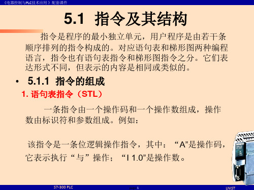
一般情况下,指令的操作数位于PLC的存储器中,此时操作数有操 作数标识符和参数组成。如图5-2所示。
图5-2 指令结构及操作数组成
S7-300 PLC
page 2
LNIST
《电器控制与PLC技术应用 》配套课件
5.2 位逻辑指令
位逻辑指令主要包括:位逻辑运算指令、位操作指令和位 测试指令,梯形图形式如图5-2所示。
图5-5 三相异步电动机的单向运转方法2
S7-300 PLC
page 6
LNIST
《电器控制与PLC技术应用 》配套课件
2. 嵌套表达式和先“与”后“或” 当控制逻辑串是串并联的复杂组合时,先 “与”后
“或”。当想先 “或” 后 “与”时,在用语句表编写程 序时要将 “或”用小括号括起来。
图6先串后并的程序结构
对累加器1中的数求反码,就是逐位取反,对累 加器1中的数求补码,求补码只有对整数或长整数才 有意义;实数取反,就是将符号位取反。 4. 用梯形图表示转换指令
在梯形图中,所有的转换指令都有对应的功能
框表示
S7-300 PLC
page 21
LNIST
《电器控制与PLC技术应用 》配套课件
5.5 运算指令
2、 定时器的启动与运行 S7中的定时器不仅功能强,而且类型多。下图给出了
为定时作业如何正确选择定时器的示意图。
S7-300 PLC
page 13
LNIST
《电器控制与PLC技术应用 》配套课件
3、 定时器梯形图方块指令
1、脉冲定时器
2、延时脉冲定时器
3. 接通延时定时器
4、带保持的接通延时定时器
4、定时器线圈指令 S7-300的五种定时器除了具有方框图指令格式外,还具
s7300新实验指导书
第一章系统概述西门子公司在S5系列PLC的基础上推出了S7系列PLC,性能价格比越来越高。
S7-300属中小型PLC,有很强的模拟量处理能力和数字运算功能,具有许多过去大型PLC才有的功能,其扫描速度甚至超过了许多大型的PLC。
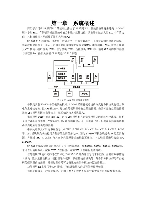
S7-300 PLC功能强、速度快、扩展灵活,它具有紧凑的、无槽位限制的模块化结构,其系统构成如图1.1所示。
它的主要组成部分有导轨(RACK)、电源模块(PS)、中央处理单元CPU模块、接口模块(IM)、信号模块(SM)、功能模块(FM)等。
通过MPI网的接口直接与编程器PG、操作员面板OP和其他S7 PLC相连。
图1.1 S7-300 PLC系统构成框图导轨是安装S7-300各类模块的机架,S7-300采用背板总线的方式将各模块从物理上和电气上连接起来。
除CPU模块外,每块信号模块都带有总线连接器,安装时先将总线连接器装在CPU模块并固定在导轨上,然后依次将各模块装入。
电源模块PS307输出24V DC,它与CPU模块和其它信号模块之间通过电缆连接,而不是通过背板总线连接。
在实际应用中,电源模块也可用开关电源代替,但要注意其输出功率必须满足所有模块的的需要。
中央处理单元CPU有多种型号,如CPU 312 IFM,CPU 313,CPU 314,CPU 315,CPU 315-2DP 等。
CPU模块除完成执行用户程序的主要任务之外,还为S7-300背板总线提供5V的直流电源,并通过MPI多点接口与其它中央处理器或编程装置通信。
本实验装置采用的是CPU 315-2DP。
S7-300的编程装置可以是西门子专用的编程器,如PG705,PG720,PG740,PG760等,也可以用通用微机,配以STEP 7软件包,并加MPI卡及编程电缆构成。
信号模块SM使不同的过程信号电平和S7-300的内部信号电平相匹配,主要有数字量输入模块、数字量输出模块、模拟量输入模块、模拟量输出模块等。
可编程序控制器PLC S7300讲义
(1) 按控制规模分类
可编程序控制器可以分为大型机、中型机和小型机。
• 小型机 : 小型机的控制点一般在256点之内,适合于单机控制或小型
系统的控制。
日本OMRON公司 CQM1
处理速度 0.5~10ms/ 1k字
存贮器
3.2~7.2k
数字量192点,模拟量44路
德国SIEMENS S7-200
处理速度 0.8~1.2ms
1. 2 可编程序控制器的特点与分类 国际电工委员会(IEC)对可编程序控制器作了如下的规定:“可
编程序控制器是一种数字运算操作的电子系统,专为在工业环境下应用 而设计。它采用可编程序的存贮器,用来在其内部存贮执行逻辑运算、 顺序控制、定时、计数和算术运算等操作的指令,并通过数字式、模拟 式的输入和输出,控制各种类型的机械或生产过程。可编程序控制器及 其有关设备、都应按易于与工业控制系统形成一个整体,易于扩充其功 能的原则设计。”这段话完全道出了可偏程序控制器的特点和应用领域 。 1. 可编程序控制器的特点
另一类设备,其输入信号是压力传感器、温度传感器、湿度传感器等 信号,输出信号是伺服电机、电动阀、距离、速度等控制信号。这类物 理量是一种连续变化量,叫做模拟量或模拟信号。
以往的电气控制装置主要采用继电器、接触器或电子元件来实现, 由连接导线将这些器件按照一定的工作程序组合在一起,以完成一定的 控制功能,这种控制叫做接线程序控制。
接线程序控制的电气装置体积大,生产周期长,接线复杂,故障率 高,可靠性差。控制功能略加变动,就需重新组合、改变接线。
2 .可编程序控制器产生
1968年,美国通用汽车公司(GM)为适应生产工艺不断更新的需 要,提出一种设想:把计算机的功能完善、通用、灵活等优点和继电器 控制系统的简单易懂、操作方便、价格便宜等优点结合起来,制成一种 通用控制装置。这种通用控制装置把计算机的编程方法和程序输入方式 加以简化,采用面向控制过程、面向对象的语言编程。使不熟悉计算机 的人也能方便地使用,并提出十项招标指标。
S7300-03编程软件的使用方法-文档资料
表7-1 用户程序中的块
块
简要描述
组织块(OB)
操作系统与用户程序的接口,决定用户程序的结构
系统功能块(SFB) CPU提供的重要系统功能,有存储区
系统功能(SFC)
CPU提供的重要系统功能,无存储区
功能块(FB)
用户编写的包含常用功能的子程序,有存储区
功能(FC)
用户编写的包含常用功能的子程序,无存储区
背 景 数 据 块 ( DI ) 调用FB和SFB时用于传递参数的数据块,编译时自动生成数据
共享数据块 (DB) 存储用户数据的数据区域,供所有块共享
5
功能块(FB、FC)实际上是用户子程序,分为带“记忆” 的功能块FB和不带“记忆”的功能块FC。FB带有背景数据 块(Instance Data Block),在FB块结束时继续保持,即被 “记忆”。功能块FC没有背景数据块。
数据块(DB)是用户定义的用于存取数据的存储区,可以 被打开或关闭。DB可以是属于某个FB的情景数据块,也可 以是通用的全局数据块,用于FB或FC。
S7 CPU还提供标准系统功能块(SFB、SFC),集成在S7 CPU中的功能程序库。用 户可以直接调用它们,由于它们是操作系统的一部分,因此不需将其作为用户程 序下载到PLC。
8
STEP7的授权 授权是使用STEP7软件的“钥匙”,只有在硬盘上找到相应的授权,STEP7才可以正常使用,否则会提示用户安装授权。
图7-2 授权管理器
9
STEP7的项目结构 在STEP7中,一个自动化系统的所有数据以项目(Project)的形式来进行组织和管理。一个项目包含了以下的三类数据。 1、硬件结构的组态数据及模块参数 2、通信网络的组态数据 3、可编程模块的程序 上述数据都以对象的形式存储,STEP7采用目录式的层次结构管理项目中的所有对象。对象从上到下有三个层次: 第一层:项目; 第二层:通讯子网、PLC站或S7程序; 第三层:第二层下面的具体对象,视第二层定。
S7300指令列表
CPU技术参数 CPU 312C - 314C-2 DP/PtP
该指令表的订货号为: 6ES7 398-8AA10-8BN0
2001年10月版
A5E00105517-01
西门子公司版权所有©2001。保留所有权利 未经明确的书面授权,禁止复制、传递或使用本手册或其中的内容。 违者必究。保留所有权利包括专利权、实用新型或外观设计专有权。 西门子股份有限公司 自动化与驱动集团 工业自动化系统部 邮政信箱4848,纽伦堡D- 90327
西门子股份有限公司
郑重声明 我们已核对过,本手册的内容与所述硬件和软件相符。但错误在所难 免,不能保证完全的一致。本手册中的内容将定期审查,并在下一版 中进行修正。欢迎提出改进意见。
®Siemens AG 2001 若有改动,恕不另行通知。
6ES7............................................................................................................................................. 1 地址标识符和参数范围....................................................................................................................................... 1 缩写词和助记符...........................................................................................................................
S7300_组织块详解
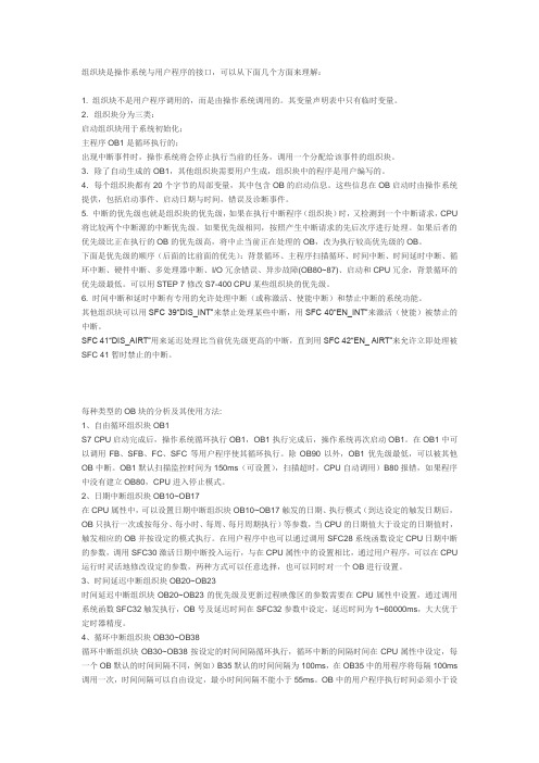
组织块是操作系统与用户程序的接口,可以从下面几个方面来理解:1. 组织块不是用户程序调用的,而是由操作系统调用的。
其变量声明表中只有临时变量。
2.组织块分为三类:启动组织块用于系统初始化;主程序OB1是循环执行的;出现中断事件时,操作系统将会停止执行当前的任务,调用一个分配给该事件的组织块。
3.除了自动生成的OB1,其他组织块需要用户生成,组织块中的程序是用户编写的。
4.每个组织块都有20个字节的局部变量,其中包含OB的启动信息。
这些信息在OB启动时由操作系统提供,包括启动事件、启动日期与时间,错误及诊断事件。
5. 中断的优先级也就是组织块的优先级,如果在执行中断程序(组织块)时,又检测到一个中断请求,CPU 将比较两个中断源的中断优先级。
如果优先级相同,按照产生中断请求的先后次序进行处理。
如果后者的优先级比正在执行的OB的优先级高,将中止当前正在处理的OB,改为执行较高优先级的OB。
下面是优先级的顺序(后面的比前面的优先):背景循环、主程序扫描循环、时间中断、时间延时中断、循环中断、硬件中断、多处理器中断、I/O冗余错误、异步故障(OB80~87)、启动和CPU冗余,背景循环的优先级最低。
可以用STEP 7修改S7-400 CPU某些组织块的优先级。
6. 时间中断和延时中断有专用的允许处理中断(或称激活、使能中断)和禁止中断的系统功能。
其他组织块可以用SFC 39“DIS_INT”来禁止处理某些中断,用SFC 40“EN_INT”来激活(使能)被禁止的中断。
SFC 41“DIS_AIRT”用来延迟处理比当前优先级更高的中断,直到用SFC 42“EN_ AIRT”来允许立即处理被SFC 41暂时禁止的中断。
每种类型的OB块的分析及其使用方法:1、自由循环组织块OB1S7 CPU启动完成后,操作系统循环执行OB1,OB1执行完成后,操作系统再次启动OB1。
在OB1中可以调用FB、SFB、FC、SFC等用户程序使其循环执行。
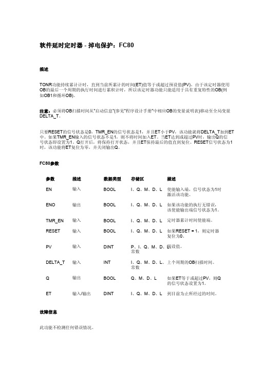
S7300_软件延时定时器 - 掉电保护:FC80
关于去留的诗句
1、相见时难别亦难,东风无力百花残。
——李商隐《无题相见时难别亦难》
2、恨君不似江楼月,南北东西,南北东西,只有相随无别离。
——吕本中《采桑子恨君不似江楼月》
3、多情只有春庭月,犹为离人照落花。
——张泌《寄人》
4、真个别离难,不似相逢好。
——晏几道《生查子关山魂梦长》
5、多情却似总无情,唯觉樽前笑不成。
——杜牧《赠别》
6、梧桐树,三更雨,不道离情正苦。
——温庭筠《更漏子玉炉香》
7、人生如逆旅,我亦是行人。
——苏轼《临江仙送钱穆父》
8、明月不谙离恨苦。
——晏殊《蝶恋花槛菊愁烟兰泣露》
9、等闲离别易销魂。
——晏殊《浣溪沙一向年光有限身》
10、死别已吞声,生别常恻恻。
——杜甫《梦李白二首其一》
11、何当重相见,尊酒慰离颜。
——温庭筠《送人东游》
12、望君烟水阔,挥手泪沾巾。
——刘长卿《饯别王十一南游》
13、乍见翻疑梦,相悲各问年。
——司空曙《云阳馆与韩绅宿别》
14、花光浓烂柳轻明,酌酒花前送我行。
——欧阳修《别滁》。
- 1、下载文档前请自行甄别文档内容的完整性,平台不提供额外的编辑、内容补充、找答案等附加服务。
- 2、"仅部分预览"的文档,不可在线预览部分如存在完整性等问题,可反馈申请退款(可完整预览的文档不适用该条件!)。
- 3、如文档侵犯您的权益,请联系客服反馈,我们会尽快为您处理(人工客服工作时间:9:00-18:30)。
Infrared Emitting Diode, RoHS Compliant, 950 nm, GaAs For technical questions, contact: emittertechsupport@Document Number: 81048TSTS7300Vishay SemiconductorsDESCRIPTIONTSTS7300 is an infrared, 950 nm emitting diode in GaAs technology in a hermetically sealed TO-18 package with lens.FEATURES•Package type: leaded •Package form: TO-18•Dimensions (in mm): ∅ 4.7•Peak wavelength: λp = 950 nm •High reliability •High radiant power •High radiant intensity•Angle of half intensity: ϕ = ± 12°•Low forward voltage•Suitable for high pulse current operation •Good spectral matching with Si photodetectors•Lead (Pb)-free component in accordance with RoHS 2002/95/EC and WEEE 2002/96/ECAPPLICATIONS•Radiation source in near infrared rangeNoteTest conditions see table “Basic Characteristics”NoteMOQ: minimum order quantityNoteT amb = 25 °C, unless otherwise specified948642PRODUCT SUMMARYCOMPONENT I e (mW/sr)ϕ (deg)λP (nm)t r (ns)TSTS73006.3± 12950800ORDERING INFORMATIONORDERING CODE PACKAGINGREMARKSPACKAGE FORMTSTS7300BulkMOQ: 1000 pcs, 1000 pcs/bulkTO-18ABSOLUTE MAXIMUM RATINGSPARAMETER TEST CONDITIONSYMBOLVALUE UNIT Reverse voltage V R 5V Forward current T case ≤ 25 °CI F 250mA Peak forward current t p /T = 0.5, t p ≤ 100 µs, T case ≤ 25 °CI FM 500mA Surge forward current t p ≤ 100 µs I FSM 2.5A Power dissipation P V 170mW T case ≤ 25 °C P V 500mW Junction temperature T j 100°C Storage temperature rangeT stg - 55 to + 100°C Thermal resistance junction/ambient leads not soldered R thJA 450K/W Thermal resistance junction/case leads not soldered R thJC150K/WDocument Number: 81048For technical questions, contact: emittertechsupport@TSTS7300Infrared Emitting Diode, RoHS Compliant, 950 nm, GaAsVishay SemiconductorsFig. 1 - Power Dissipation Limit vs. Ambient Temperature Fig. 2 - Forward Current Limit vs. Ambient TemperatureNoteT amb = 25 °C, unless otherwise specifiedBASIC CHARACTERISTICST amb = 25°C, unless otherwise specifiedFig. 3 - Pulse Forward Current vs. Pulse DurationFig. 4 - Forward Current vs. Forward VoltageBASIC CHARACTERISTICSPARAMETER TEST CONDITION SYMBOLMIN.TYP.MAX.UNIT Forward voltageI F = 100 mA, t p ≤ 20 msV F 1.3 1.7V Temperature coefficient of V F I F = 100 mA TK VF - 1.3mV/K Breakdown voltage I R = 100 µAV (BR)5V Junction capacitance V R = 0 V, f = 1 MHz, E = 0Cj 30pF Radiant intensity I F = 100 mA, t p = 20 ms I e 4 6.332mW/sr Radiant powerI F = 100 mA, t p ≤ 20 msφe 7mW Temperature coefficient of φe I F = 100 mATK φe - 0.8%/K Angle of half intensity ϕ± 12deg Peak wavelength I F = 100 mA λp 950nm Spectral bandwidth I F = 100 mA Δλ50nm Rise timeI F = 100 mAt r 800ns I F = 1.5 A, t p /T = 0.01, t p ≤ 10 µst r 400ns Virtual source diameterd1mmTSTS7300Vishay Semiconductors Infrared Emitting Diode, RoHS Compliant,950 nm, GaAsFig. 5 - Relative Forward Voltage vs. Ambient Temperature Fig. 6 - Radiant Intensity vs. Forward CurrentFig. 7 - Radiant Power vs. Forward Current Fig. 8 - Relative Radiant Intensity/Power vs. Ambient Temperature Fig. 9 - Relative Radiant Power vs. Wavelength Fig. 10 - Relative Radiant Intensity vs. Angular Displacement For technical questions, contact: emittertechsupport@ Document Number: 81048TSTS7300Infrared Emitting Diode, RoHS Compliant,Vishay Semiconductors950 nm, GaAsPACKAGE DIMENSIONS in millimetersDocument Number: 81048For technical questions, contact: emittertechsupport@ Disclaimer Legal Disclaimer NoticeVishayAll product specifications and data are subject to change without notice.Vishay Intertechnology, Inc., its affiliates, agents, and employees, and all persons acting on its or their behalf (collectively, “Vishay”), disclaim any and all liability for any errors, inaccuracies or incompleteness contained herein or in any other disclosure relating to any product.Vishay disclaims any and all liability arising out of the use or application of any product described herein or of any information provided herein to the maximum extent permitted by law. The product specifications do not expand or otherwise modify Vishay’s terms and conditions of purchase, including but not limited to the warranty expressed therein, which apply to these products.No license, express or implied, by estoppel or otherwise, to any intellectual property rights is granted by this document or by any conduct of Vishay.The products shown herein are not designed for use in medical, life-saving, or life-sustaining applications unless otherwise expressly indicated. Customers using or selling Vishay products not expressly indicated for use in such applications do so entirely at their own risk and agree to fully indemnify Vishay for any damages arising or resulting from such use or sale. Please contact authorized Vishay personnel to obtain written terms and conditions regarding products designed for such applications.Product names and markings noted herein may be trademarks of their respective owners.元器件交易网Document Number: 。
