SD1053C28S20L中文资料
智能电容状态显示器
智能电容状态显示器使用说明书苏州士林电机有限公司版本号:SC07_V18.12.6目录一.产品概述 (1)二.功能特点 (1)三.使用环境 (1)四.技术参数 (1)五.机械安装 (2)六.电气接线 (2)七.面板说明 (2)八.调试与运行 (4)1.工作指示灯 (4)2.闭锁指示灯 (4)3.通讯指示灯 (4)4.分补、共补指示灯 (4)九.售后服务 (5)1.质保期 (5)2.技术支持 (5)一.产品概述本产品为我公司最新研制,与本公司智能低压电力电容器配套使用,代替传统的电容指示灯和功率因数表。
该产品集成化程度高,外形美观大方,通用仪表尺寸,安装方便,接线简单,能大大提高整柜生产效率,整体提升产品质量。
二.功能特点1、混补显示面板上集成70只高亮LED指示灯,最多可同时指示20只共补电容和10只分补电容状态,共补显示器显示面板上集成70只高亮LED指示灯,最多可指示32只共补电容状态;LED指示灯功耗小,亮度高。
2、采用数字通讯方式,与智能低压电力电容器交换信息,自动采集系统功率因数和电容状态信号,并快速刷新显示。
3、自带通讯故障检测,当通讯总线故障或无通讯时,数码管熄灭需要检查通讯。
三.使用环境海拔高度≤3000m,湿度≤90%(20℃),环境温度为-20℃-60℃,大气压力为79.5-106.5kpa,无易燃易爆的介质存在,无导电尘埃及腐蚀性气体存在。
四.技术参数额定电压:交流50Hz,380V±20%额定功耗:不大于3VA五.机械安装在屏柜上开113*113mm的方孔,将本产品从屏前推入方孔内,把配给的塑料紧固件插入安装槽中,上紧即可固定在屏上。
六.电气接线电气接线按下图输出端子定义准确接线(共补混补接线方式相同)。
状态显示器接线端子图图中,电源接入380V电压,其波动应在允许范围内;电容显示器与智能低压电力电容器之间的通讯总线连接采用产品配套的数据线直接插拔连接。
七.面板说明1、混补显示器面板说明:2、共补显示器面板说明:八.调试与运行检查接线,确认无误后,接通电源,数码管显示“PF”,5秒后,数码管轮流显示各相位的功率因数,电容状态显示器即工作于自动状态。
SD200-50、75伺服驱动器用户手册
2SC3998中文资料(sanyo)中文数据手册「EasyDatasheet - 矽搜」
10 7
μs 5
3
2
SW时间 - IC
tstg
2SC3998
IC=5IB1 IB2= --2IB1 VCC=200V R称重
10
7
μs 5
3 2
SW时间 - IB2
tstg
VCC=200V IC=12A IB1=2.4A R称重
1.0 7
开关时间5 ,SW时间 -
3
tf
2
0.1 5
7 1.0
100
ICP=50A
5
基极电流IB2 - 一个
反向偏置一个S 0
100
5
3 2
10
5 3 2
集电极1.0电流,IC - 一个
5
3 2
7 10
2
ITR06231
IB2= --5A L=100μH
单脉冲
Tc=25°C
0.1
5
5 7 100
23
5 7 1000
集电极 - 发射极维持电压,VCEX(SUS) - V
PC - 锝
5
3 IC=25A
2
10
5 3 2
1.0
5
集电极3电流,IC - 一个
2
0.1
23
5 7 10
集电极电流,IC - 一个
正向偏置S 0
PC=250W
1m s
DCopera1tio0mns
23
5
ITR06230
300μs
5 3 2 0.01
3
4.0
5 7 10
2 3 5 7 100
集电极 - 发射极电压VCE - V
技术指标
绝对最大额定值
深川变频S280系列防爆变频器机芯说明书

S280系列防爆变频器机芯使用说明书资料版本 V1.1归档日期 2022-08-30企业标准: Q/913703SSC002-2019山东深川变频科技股份有限公司为客户提供全方位的技术支持,用户可与就近的山东深川变频科技股份有限公司办事处或客户服中心联系,也可直接与制造商联系。
版权所有,保留一切权利。
内容如有改动,恕不另行通知。
总部:山东深川变频科技股份有限公司客户热线:400-812-8821技术支持:400-812-6621质量反馈:400-812-0778投 诉:400-812-6125网 址:目录S280系列防爆变频器机芯说明书目 录第1章 安全及注意事项 (1)1.1 安全事项 (1)1.2 注意事项 (1)第2章 技术指标及选型 (2)2.1 命名规则 (2)2.2 铭牌 (2)2.3 型号与技术参数 (2)2.4 技术规范 (3)2.5 S280‐FB系列厂用防爆变频器通用机芯产品外形图、安装孔位尺寸 (4)2.6 S280‐RG系列中压防爆变频器热管机芯产品外形图、安装孔位尺寸 (11)2.7 键盘的外形尺寸 (12)2.8 制动组件选型推荐 (13)第3章 电气安装 (14)3.1 外围电气元件选型指导 (14)3.2 主回路端子及接线 (15)第4章 键盘操作与显示 (18)第5章 功能参数简表 (20)第6章 重点功能参数详解 (40)第7章 通讯协议 (48)第8章 故障检查与排除 (51)8.1 故障信息与排除方法 (51)8.2 常见故障及其处理方法 (53)S280系列防爆变频器机芯说明书第1章安全及注意事项第1章 安全及注意事项1.1 安全事项1、应由电气专业技术人员安装、调试变频器,否则有触电危险!2、接线前请确认电源处于关断状态,否则有触电危险!3、接地端子必须可靠接地,接地电阻应小于0.1Ω!4、不能将输入电源连到输出端U、V、W,否则引起变频器损坏!5、确保配线导线线径符合技术标准,否则可能发生事故!6、变频器无须进行耐压测试,出厂时产品此项已做过测试,否则可能引起事故!7、上电后不要触摸变频器端子(含控制端子),否则有触电危险!8、若要进行参数自学习,请注意电机旋转中伤人的危险,否则可能引起事故!9、不要采用接触器通断的方式来控制变频器的启停,否则引起设备损坏!10、断开电源后因滤波电容上仍然有高压,所以不能马上对变频器进行维修或保养,必须等待5分钟以上后用万用表测母线电压((+)和(-)之间的电压)不超过36V才可进行。
SD2010 说明书
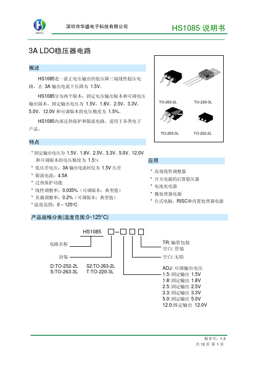
深圳市华盛 HS1085说明书
HS1085-2.5,
IOUT=10mA, VIN=5.5V 10mA≤IOUT≤3A, 2.462 2.5 2.537
V
VOUT
4.0V≤VIN ≤7V HS1085-3.3,
2.45
2.5
2.55
IOUT=10mA, VIN=6.3V, 10mA≤IOUT≤3A, 3.225 3.3 3.350
版本号:1.3 共 12 页 第 2 页
深圳市华盛电子科技有限公司
产品名称 HS1085S2-1.5 HS1085S2-1.5TR HS1085S2-1.8 HS1085S2-1.8TR HS1085S2-2.5 HS1085S2-2.5TR HS1085S2-3.3 HS1085S2-3.3TR HS1085S2-5.0 HS1085S2-5.0TR
11.88 12.00 12.12 V
11.76 12.00 12.24
HS1085-ADJ, IOUT=10mA, 2.85V≤VIN≤10V
0.035 0.2
%
HS1085-1.5, IOUT=10mA, 3.0V≤VIN≤10V
1
6
mV
HS1085-1.8, ∆VOUT
IOUT=10mA, 3.3V≤VIN≤10V
内部框图
封装形式
打印名称 HS1085S2-1.5 HS1085S2-1.5 HS1085S2-1.8 HS1085S2-1.8 HS1085S2-2.5 HS1085S2-2.5 HS1085S2-3.3 HS1085S2-3.3 HS1085S2-5.0 HS1085S2-5.0
VIN
HS1085 说明书
封装形式 TO-252-2L
TO-263-3L TO-220-3L TO-263-2L
广州华盛通电子有限公司 HXLVDSR 四路 LVDS 差分线电阻器商品说明书
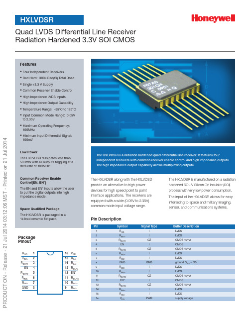
The HXLVDSR along with the HXLVDSD provide an alternative to high power devices for high speed point to point interface applications. The receivers are equipped with a wide (0.05V to 2.35V) common mode input voltage range.The HXLVDSR is manufactured on a radiation hardened SOI-IV Silicon On Insulator (SOI) process with very low power consumption. The input of the HXLVDSR allows for easy interfacing to space and military imaging, sensor, and communications systems.Quad LVDS Differential Line Receiver Features▪ F our Independent Receivers ▪ R ad Hard: 300k Rad(Si) Total Dose ▪ S ingle +3.3 V Supply ▪ C ommon Receiver Enable Control ▪ H igh Impedance LVDS Inputs ▪ H igh Impedance Output Capability ▪ T emperature Range: -55°C to 125°C ▪ I nput Common Mode Range: 0.05Vto 2.35V▪ M aximum Operating Frequency:100MHz ▪ M inimum Input Differential Signal:100mVLow PowerThe HXLVDSR dissipates less than 500mW with all outputs toggling at a data rate of 100MHz.Common Receiver Enable Control(EN, EN*)The EN and EN* inputs allow the user to put the digital outputs into high impedance mode.Space Qualified Package The HXLVDSR is packaged in a 16 lead ceramic flat pack.The HXLVDSR is a radiation hardened quad differential line receiver. It features fourindependent receivers with common receiver enable control and high impedance outputs. The high impedance output capability allows multiplexing outputs.Pin DescriptionPackage PinoutP R O D U C T I O N - R e l e a s e - 21 J u l 2014 03:12:06 M S T - P r i n t e d o n 21 J u l 2014Block DiagramTruth TableFunctional DescriptionThe HXLVDSR is a radiation hardened quad differential line receiver designed for applications requiring low power dissipation and high data rates. The HXLVDSR accepts low voltage differential input sig-nals and translates them to 3.3V CMOS output levels. The receiver includes high impedance output capability to allow multiplexing outputs. The EN and EN* inputs allow active Low or active Highcontrol of the high impedance outputs. The enable signals are common to all four receivers. The dual enable scheme allows for flexibility in turning devices on or off. The HXLVDSR along with the HXLVDSD provide an alternative to high power devices for high speed point to point interface applications.R OUT1R OUT2R OUT3R OUT4R IN2+R IN2-R IN3+R IN3-R IN4+R IN4-EN EN*R IN1+R IN1-Signal DefinitionEN, EN*These are the common enable control signals. As shown in Truth Table, the combination of EN = L and EN* = H puts the outputs into the high impedance state. The outputs are enabled for all other combinations of EN and EN*.R IN1 – R IN4These are LVDS differential input pins.R OUT1 – R OUT4These are the 3.3V CMOS output pins.Absolute Maximum Ratings (1)(1) Stresses above the absolute maximum ratings may cause permanent damage to the device. Extended operation at the maximum levels may degrade performance and affect reliability.(2) One output at a time should be shorted and the max junction temperature should not be exceeded.2Recommended Operating Conditions (1)(2)Electrical RequirementsConditions unless otherwise specified: 3.0 V ≤ VDD ≤ 3.6 V, -55°C ≤ TC ≤ +125°C, VSS = 0 V(1) G uaranteed but not tested.(2) The VCMR range is reduced for larger V ID.3(1) S pecifications listed in datasheet apply when used under the Recommended Operating Conditions unless otherwise specified.(2) A ll unused CMOS inputs must be held at ground or VDD. All unused LVDS inputs must be held at ground or 2.4 volts differentially.Radiation-Hardness Ratings (1)(1) Device will not latch up due to any of the specified radiation exposure conditions.Capacitance Parameters (1)(1) G uaranteed but not tested.4Radiation CharacteristicsTotal Ionizing Dose RadiationThe device radiation hardness assurance TID level was qualified by 60Co testing, including overdose and accelerated annealing, per MIL -STD-883 Method 1019. Ongoing assurance is provided by wafer level X-ray testing during manufacturing.Transient Dose Rate Ionizing RadiationMany aspects of product design are addressed to handle the high energy levels associated with the transient dose rate events. The device will maintain basic functional operation during exposure to a pulse up to the DRU specification. The device will meet functional, timing and parametric specifications after exposure to a pulse up to the DRS specification.Neutron Irradiation DamageSOI CMOS is inherently tolerant to damage from neutron irradiation. The device meets functional and timingspecifications after exposure to the specified neutron tchupThe device will not latchup when exposed to any of the above radiation environments when applied under recommended operating conditions. SOI CMOS provides oxide isolationbetween adjacent PMOS and NMOS transistors and eliminatesany potential SCR latchup structures.Switching ParametersTest Conditions unless otherwise specified: 3.0 V ≤ VDD ≤ 3.6 V, -55°C ≤ TC ≤ +125°C, VSS = 0 V(1) G uaranteed but not tested by vendor.(2) M aximum LVDS Receiver Jitter performance is guaranteed between -5°C and 125°C case temperature, between 3.0 V and 3.6 V; and pre- and post-radiation. (3) AC sine wave Power Supply Noise of 60 mV p-p applied at 25 MHz.(4) The skew is the absolute value of the difference between the differential propagation delay High to Low and the differential propagation delay Low to High of the same channel. (5) The skew is the channel-to-channel difference of the differential propagation delays for any event on the same device. (6) T he skew is the absolute value of the difference between the minimum and maximum differential propagation delays between devices.Devices must be at the same VDD and within 5°C of each other. (7) T he skew is the absolute value of the difference between the minimum and maximum differential propagation delays between devices.(8) Cload = 10pFTiming DiagramsEN when EN* = V DDOutput when V ID = -100 mV V DD O VV OH50%1.5 VV OL 50%3 V GNDO V 1.5 V 3 V EN* when EN = GNDOutput when V ID = +100 mV5ReliabilityFor many years Honeywell has been producing integrated circuits that meet the stringent reliability requirements of space and de-fense systems. Honeywell has delivered hundreds of thousands of QML parts since first becoming QML qualified in 1990. Using this proven approach Honeywell will assure the reliability of the products manufactured with the SOI CMOS process technology. This approach includes adhering to Honeywell’s Quality Manage-ment Plan for:• D esigning in reliability by establishing electrical rules based on wear out mechanism characterization performed on specially designed test structures (electromigration, TDDB, hot carriers, bias temperature instability and radiation).• Utilizing a structured and controlled design process.• S tatistically controlling wafer fabrication process with a continuous defect reduction process.• P erforming individual wafer lot acceptance through process monitor testing (includes radiation testing).• Using characterized and qualified packages.• P erforming thorough product testing program basedon MIL-PRF-38535 and MIL-STD 883.Screening and Conformance InspectionThe product test flow includes screening units with the applicable flow (Engineering Model, QML V, QML Q, Class V and Q equiva-lent) and the appropriate periodic or lot conformance testing (Groups A, B, C, D, and E). Both the wafer process and the prod-ucts are subject to periodic or lot based Technology Conformance Inspection (TCI) and Quality Conformance Inspection (QCI) tests as defined by Honeywell’s Quality Management Plan. Conformance SummaryPackage Outline Dimensions6Signal IntegrityAs a general design practice, for digital input signals, one should have good signal integrity which means input signals that are free of noise, glitches and ringing with rising and falling edges of ≤10ns. More specifically, an input is considered to have good signal integrity when the input voltage monotonically traverses the region between VIL and VIH in ≤10ns.Floating inputs for an extended period of time is not recommended.Honeywell Aerospace Honeywell 12001 Highway 55Plymouth, MN 55441Tel: 800-323-8295/ADS-14204 Rev A June 2014© 2014 Honeywell International Inc.Find out moreTo learn more about Honeywell’s radiation hardened integrated circuit products and technologies, visit/Honeywell reserves the right to make changes of any sort without notice to any and all products, technology and testing identified herein. You are advised to consult Honeywell or an authorized sales representative to verify that the information in this data sheet is current before ordering this product. Absent express contract terms to the contrary, Honeywell does not assume any liability of any sort arising out of the application or use of any product or circuit described herein; nor does it convey any license or other intellectual property rights of Honeywell or of third parties.QCI Testing (1)(1) Q CI groups, subgroups and sample sizes are defined in MIL -PRF38535 and the Honeywell Quality Management Plan. Quarterly testing is done in accordance with the Honeywell QM Plan.(2) If customer requires lot specific testing, the purchase order must indicate specific tests and sample sizes.Ordering Information(1) Orders may be faxed to 763-954-2051. Please contact our Customer Service Representative at 1-763-954-2474 for further information.(2) E ngineering Device Description: Parameters are tested -55°C to 125°C, 24 hour burn-in, no radiation hardness guaranteed. Screen Level and Total Dose Hardnesscodes must be “E” and “N” respectively.Process X = SOI CMOS Screen Level V = QML V W = QML Q+E = Eng. Model (2)Source H = HoneywellPackage Designation G = 16 Pin Flat PackTotal Dose Hardness F = 3x10⁵ rad (Si)N = No Level Guaranteed (2)Part Type R = ReceiverPart NumberStandard Microcircuit DrawingThe HXLVDSR can be ordered under the SMD drawing 5962-07A03.。
宝德 NS 系列服务器 说明书
宝德NS系列服务器用户手册声明本手册可能会出现技术或排版印刷的错误,因此深圳市宝德计算机系统有限公司会定期修订此手册,并将修改后的内容纳入新版本中。
深圳市宝德计算机系统有限公司拥有对产品、程序进行改进、更新的权力。
深圳市宝德计算机系统有限公司对于在非深圳市宝德计算机系统有限公司提供的设备上使用本公司软件的可靠性概不负责。
本手册中载有受版权保护的专利信息,版权所有,未经深圳市宝德计算机系统有限公司的事先书面许可,本手册中的任何内容均不得复印、翻印或翻译。
Powerleader是深圳宝德科技集团股份有限公司的注册商标。
Intel,XEON 是Intel公司的注册商标。
Microsoft是Microsoft公司的注册商标。
Redhat 是Red Hat 公司的注册商标。
所有其它公司或产品名称分别是持有者的商标或服务标志。
简介本手册主要描述了如何对宝德系列服务器进行操作、升级、配置和疑难解答,它可使操作者熟悉宝德系列服务器并为将来可能出现的问题提供参考。
章节说明本手册包括以下内容:1.使用准备2.系统结构描述3.系统说明与设置4.BIOS设置5.集成RAID配置6.操作系统安装说明7.系统故障诊断特殊标志手册中出现以下三种特定提示标志:警告:会引起人身伤害及灾难性的行为注意:会引起硬件损坏或造成软件故障的行为注释:提供重要信息目录第一章使用准备 (1)1.1摘要 (1)1.2检查运输包装 (1)1.3选择一个放置服务器的合适位置 (1)1.4把服务器安装在机架上 (2)1.5检查电源线 (2)1.6增加设备 (2)1.7连接外围设备 (2)1.8打开显示器和服务器 (3)第二章系统结构描述 (4)2.1PR2012NS机箱特性 (4)2.2PR3016NS机箱特性 (6)2.3PR4016NS机箱特性 (7)2.4PR4020NS机箱特性 (8)2.5PR4024NS机箱特性 (10)2.6PR2024NS机箱特性 (12)2.7服务器后窗连接示意图 (13)2.8跳线设置 (14)第三章系统说明与设置 (16)3.1主板布局图 (16)3.2CPU (17)3.3内存 (17)3.4视频控制器 (18)3.5硬盘控制器 (18)3.6网络控制器 (18)3.7键盘和鼠标 (18)3.8光驱和软驱 (18)3.9PCI扩展 (18)3.10其他配置 (18)3.11认证兼容操作系统 (18)第四章BIOS设置 (19)第五章集成RAID 配置 (40)5.1 在BIOS中设置RAID状态 (40)5.2 主板集成RAID的操作指南 (40)第六章操作系统安装说明 (56)6.1 Microsoft Windows 2003 Enterprise Server安装说明 (56)6.2 Microsoft Windows 2008 Enterprise Server安装说明 (72)6.3 Red Hat Enterprise Linux AS 5.0 U3操作系统和驱动程序安装说明 (81)第七章系统故障排除 (99)7.1系统复位介绍 (99)7.2系统首次启动 (99)7.3其他问题及解决办法 (100)7.3.1准备系统进行诊断程序 (100)7.3.2验证系统指示灯 (100)7.4具体问题 (101)7.4.1电源灯不亮 (101)7.4.2屏幕不显示字符 (101)7.4.3屏幕显示字符不正确或字符扭曲 (101)7.4.4系统风扇转动不正常 (102)7.4.5 硬盘驱动器的工作指示灯不亮 (102)7.4.6 CD-ROM驱动器的工作指示灯不亮 (102)7.4.7 可引导光盘不能自引导 (103)第一章使用准备1.1摘要本章内容的主要任务是讲述如何做一些基本的准备工作。
SD伺服驱动器说明书

精心整理第一章简介1.1产品简介交流伺服技术自八十年代初发展至今,技术日臻成熟,性能不断提高,现已广泛应用于数控机床、印刷包装机械、纺织机械、自动化生产线等自动化领域。
SDXXX系列交流伺服是本公司自主研发的新一代交流伺服驱动器,主要采用最新的IRMCK201作为核心运算单元,并采用了复杂可编程器件EPLD及三菱智能功率模块,具有集成度高,体积小,响应速度快,保护完善,可靠性高等一系列优点。
适用于高精度的数控机床、自动★★★。
★★★★★★1.21S D30MT采用空间矢量调制方式(SVPWM)的交流伺服驱动器第二章安装【注意】☆产品的储存和安装必须满足环境条件要求。
☆产品的安装需要防火材料,不得安装在易燃物上面或附近,防止火灾。
☆伺服驱动器须安装在电气控制柜内,防止尘埃、腐蚀性气体、导电物体、液体及易燃物侵入。
☆伺服驱动器和伺服电机应避免振动,禁止承受冲击。
☆严禁拖拽伺服电机电线、电机轴和编码器。
2.1安装场合◎电气控制柜内的安装驱动器的使用寿命与环境温度有很大的关系。
电气控制柜内部电气设备的发热以及控制柜内的散热条件,都会影响伺服驱动器周围的温度,所以在考虑机箱设计时,应考虑驱动器的散热冷却以及控制柜内的配置情况,以保证伺服驱动器周围环境温度在55℃以下,相对湿度95%以下。
长期安全工作温度在45℃以下。
◎伺服驱动器附近有发热设备2.2注:☆☆☆1.(1(2环境温度0-50℃,长期安全工作温度在45℃以下,相对湿度在90%以下,并应保证良好的散热条件。
(3)振动与冲击驱动器安装应避免振动,采取减振措施控制振动在0.5g(4.9m/S2)以下,驱动器安装应不得承受重压和冲击。
2、通风间隔3、安装方法(1)安装方式电机采用凸缘安装方式,电机安装方向任意。
(2)安装注意事项第三章接线【注意】☆外部交流电必须经隔离变压器后才能接到伺服驱动器上。
☆必须按端子电压和极性接线,防止设备损坏或人员伤害。
☆驱动器和伺服电机必须良好接地。
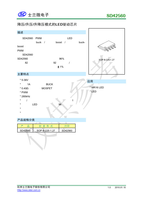
SD42560 LED驱动芯片说明书
1. PWM 调光功能 SD42560 内部设定 PWM 调光功能。当 PWM 电压悬空或者接高电平时,芯片正常工作,当
PWM 电压接低电平时,COMP 脚与芯片断开,电容上的电荷处于保持状态,电平保持,电流比较
杭州士兰微电子股份有限公司
版本号:1.0 2010.01.10 共8页 第4页
功率管漏电流 电流限制 最大占空比 振荡频率
PWM 调光脚开启电压
PWM 调光脚关断电压
PWM 脚下拉电流 PWM 脚上拉电流 COMP 端箝位电压 开关管导通电阻 VDD 电压 采样电压阈值
符号
测试条件
最小值 典型值 最大值
VIN VCC=5/36V,
IIN VPWM=5V
IL
VSW=36V
5
36
I/O 补偿端,外接补偿元件。
6
PWM
I PWM 调光端,外接 PWM 信号改变输出电流的大小。
7
VDD
I 5V 基准输出端。
8
VIN
I 输入电压。
功能描述
SD42560 是电流模式的 LED 驱动电路,可以应用与降压模式(Buck),升压模式(Boost),升 降压模式(Buck-Boost)三种模式。用于满足不同的 LED 应用。
升压/降压模式的工作原理为:在一个工作周期的开始时,内部振荡器输出触发信号,将芯片 内部功率管导通,SW 输出低电平,VIN,电感和内部开关管,GND 组成通路,给电感储能,电感 上的电流增加。LED 上的电流通过 SENSE-和 SENSE+进行采样,将采样值与阈值进行误差放 大,输出信号再与功率管的峰值电流进行比较,当功率管的峰值电流值达到误差放大输出值时, 功率管截止。电感,肖特基,Rs,LED 组成的回路给 LED 供电,电感电流降低。在下一个时钟到 来时,开关管开通,进入下一个开关周期。
SDD系列多功能数显仪表

三 排 数 码 管( L E D ), 数 字 显 示 有 功 电 能( K w h )、 无 功 电 能( K v a r h )
三 排 数 码 管( L E D ), 数 字 显 示 三 相 电 流(Ⅰ)、 有 功 电 能( K w h )
三 排 数 码 管( L E D ), 数 字 显 示 电 压( U )、 电 流(Ⅰ)、 有 功 电 能( K w h )
产品规格代码说明多功能电力仪表型号1201207742方形开孔尺寸106106mm96967796方形开孔尺寸9191mm80808780方形开孔尺寸7676mm72728772方形开孔尺寸6767mm测量仪表带485通讯2路电能脉冲三排数码管led数字切换显示全部电量三排数码管led数字显示有功电能kwh无功电能kvarh三排数码管led数字显示三相电流有功电能kwh三排数码管led数字显示电压u电流有功电能kwhlcd液晶显示全部电能通用技术条件主要项目技术指标额定值过负荷额定值过负荷脉冲输出工作范围绝缘电阻绝缘强度工作条件ui为05级
*
*
*
A
B C N
三 相 四 线 电 流 经C T输 入 , 电 压 直 接 输 入
9 10 11 12 13 14 1 7 16 15 18
*
*
A
B C
三 相 四 线 电 流 经C T输 入 , 电 压 直 接 输 入
注 : 图中符号 "*" 表示电流进线端。
9 10 11 12 13 14 17 16 15 18
型号说明
型号
代码
说明
SDD194E
-□ T □ □
SDD194E
多功能电力仪表型号
外形尺寸
基本功能 显示方式
8路分线主机使用说明书
三、面板
指示灯和功能如下表
指示灯
功能
正常 该通道信号正常
故障 该通道故障
报警 该通道浓度超出报警点
输出 该通道输出
主电工作 表示主电源正在工作
主电故障 主电源故障
备电工作 备电开始工作
备电故障 备电源故障
通讯指示 正在通讯
消音指示 亮起时表示不输出声音报警
系统故障 控制器内部出现故障
公共报警 任何报警都点亮
二、技术参数
1,规格型号:*** 2,供电电压:主电 AC200V (50\60)Hz
备电 DC24V,7AH 3,工作温度:-20℃-50℃ 4,工作湿度:≤80%RH 5,测量范围:0-100%LEL(可燃气体)
(可根据具体传感器配置其他量程) 6,报警浓度:低报 20,高报 50
(可根据具体传感器配置其他浓度) 7,基本误差:<±5%(F.S) 8,响应时间:<60S 9,输出容量:AC220V 5A,DC30V 10A 10,输出通道:10 路开关量,1 路 AC220V,1 路 DC24V 11,报警音量:≥80 分贝 12,探测器接入:三线制 4-20ma 13,通讯方式:RS485 14,报警记录:≤2000 条 15,安装方式:壁挂 16,外形尺寸:宽*高*厚=350*450*130mm
报警点设置
每个通道低报、高报数值
通道屏蔽设置
打开或者关闭相应通道
每种设置都是通过“左右”按键进行移位反白显示选
择,然后用“上下”按键就行数据的更改。最后按“确
认”保存数据,按“取消”按键不保存数据按“联动”按键进入联动操作界面,分机 有 8 个对应的继电器,主机有 4 个继电器,移位选择 对应的继电器并按“联动”可以使该继电器在“自动”
海信小家电产品介绍

海信牌电磁炉CL2080
●简约设计,便捷操作,简约厨房新概念 ●全屏触摸式按键,时尚触感 ●优质黑晶面板,超耐磨,抗冲击, 持久不变色 ●原装进口IGBT,性能稳定,品质持久 ●四位数码显示、电量清晰显示 ●24小时预约,3小时定时,烹饪更轻松 ●2000W超强火力,多段火力调节,美味智在掌控 ●美食烹饪功能:火锅、炒菜、烧烤、烧水、爆炒、煮粥、煲汤、煎炸、 热奶。 功率2000W,3级能效
海信小家电系列手册
2009年11月 2009年11月
产品目录:
电热水壶系列(5款) 电磁炉系列(5款) 电饭煲系列(4款) 电压力锅系列(5款)
电水壶系列
品类 电水壶 电水壶 电水壶 电水壶 电水壶 海信型号 SH0801 SH1201 SH1501 SH1502M SH1802M 产品档次 中端 中端 中端 中端 中端 备注 容积0.8L 容积1.2L 容积1.5L 容积1.5L 容积1.8L
海信牌电饭煲FBJ402/FBJ502 海信牌电饭煲
按下煮饭,简单操作 高强度合金铝不粘内胆,耐用不易变形 可拆卸防溢保湿蒸汽阀,保持食物水份 加厚发热盘,加热更均匀 容积4升/5升,机械式控制
海信牌电饭煲FBJ405S 海信牌电饭煲
全新微压力结构,米饭更营养 创意密封阀设计,锁住食物营养 简易可拆卸防凝露保温盖板,清洗更方便 新专利双切技术,煮饭煲粥自由切换 容积4升,机械式控制
电饭煲系列
品类 海信型号 产品档次 备注
电饭煲 电饭煲 电饭煲 电饭煲
FBJ301 FBJ402 FBJ502 FBJ405S
特价机 中端 中端 高端
容积3L 容积4L 容积5L 容积4L
海信牌电饭煲FBJ301 海信牌电饭煲
容积3升,机械式控制 按下煮饭,简单操作 高强度合金铝不粘内胆,耐用不易变形 可拆卸防溢保湿蒸汽阀,保持食物水份 加厚发热盘,加热更均匀
mb89f202中文资料

敞末让开端没。没有有使使用用的的I/O输末入端末进端入会输引出起状误态动后作并和把锁其定敞,开造;成如永其久在性输损入害状,态故,请就用按2照kΩ输或入以末上端的的电处阻理上方拉法或处下理拉该末等端I/。O
• N.C. 管脚的处置
(转下页)
6
系列 MB89202
(承上页) 管脚编号
SH-DIP32*1 SSOP34*3
24-27 26-29
21-23 32 10
23-25 34 10
管脚名称
P40/AN0 |
P43/AN3 P70-P72
VCC VSS
16
17
C
, — 16 22 :*1 DIP-32P-M06 :*2 FPT-34P-M03
(转下页)
2
系列 MB89202
(承上页)
产品型号 参数
MB89202
MB89F202
MB89V201
10 位 A/D 转换器 1A通0/D过位转精8换/度1功6×位能8定(个时转通器换道时/ 计间数:器1输2.出16或µ时s/1基2.定5 时MH器z计) 数器连续激活
Wild 寄存器
位8 × 2
:有 ×:无
MB89202 ×
MB89F202 ×
MB89V201 × ×
■ 产品间的差异
• 存储器容量
使用评价产品进行评价之前, 请先确认其与实际使用产品的差异。
• 屏蔽选项
产品不同,可以选择的项目和指定选项的方法也不同。选择之前,请查阅 “■ 屏蔽选项”一览表。
3
系列 MB89202
■ 管脚图
P33/EC
15
N.C.
16
C
SD05C中文资料
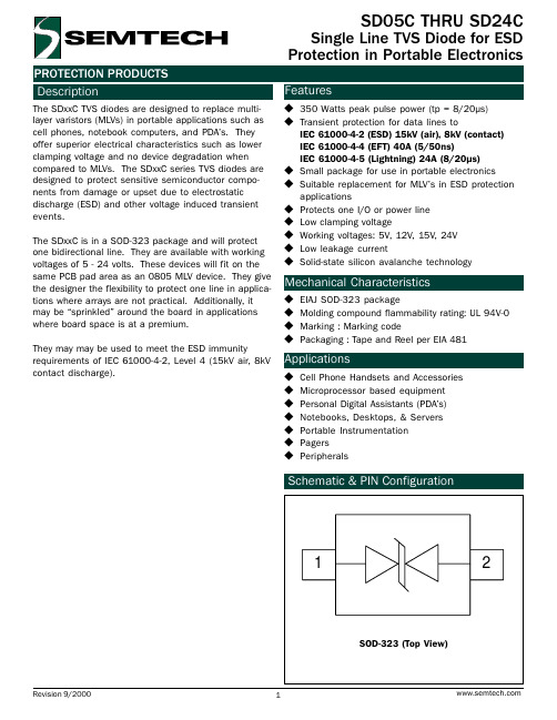
Symbol Ppk IPP VPP TL TJ TSTG
Value 350 24 30 260 (10 sec.) -55 to +125 -55 to +150
Units Watts
A kV °C °C °C
Electrical Characteristics
SD05C TVS for 5V Lines Parameter
Reverse Stand-Off Voltage Reverse Breakdown Voltage Reverse Leakage Current Clamping Voltage Clamping Voltage Junction Capacitance
Symbol VRWM VBR IR VC VC Cj
10
Peak Pulse Power - PPP (kW)
1
0.1
0.01 0.1
110 100
90 80 70 60 50 40 30 20 10
0 0
1
tp (µs)
1000
Pulse Waveform
Waveform Parameters:
tr = 8µs td = 20µs
Applications
u Cell Phone Handsets and Accessories u Microprocessor based equipment u Personal Digital Assistants (PDAs) u Notebooks, Desktops, & Servers u Portable Instrumentation u Pagers u Peripherals
They may may be used to meet the ESD immunity requirements of IEC 61000-4-2, Level 4 (15kV air, 8kV contact discharge).
温控开关-鑫动8802的说明书

鑫动8802系列温控器使用手册尊敬的客户,首先感谢您选用本公司产品。
◆在您安装和使用前请仔细阅读本说明书,从而保证您的正确安装和使用。
◆按规定的额定电流使用,严禁超载。
◆严格执行电工标准、准确按照温控器底壳上的接线图接线。
一、使用环境1、本产品电子集成度高,禁止在潮湿或温度高于50℃的环境下使用。
2、本产品采用上下散热孔形式散热,为避免在装饰墙体时大量灰尘进入机体,出厂前已在温控器上散热孔处贴上防尘膜,请务必在装饰完墙体之后将其撕掉。
3、如使用外置传感器请将其穿入埋线管中,放置于需要测温的地点,且勿将传感器直接接触水泥沙浆。
二、功能特点◆分体式安装结构,安装简单方便◆旋钮式温度设定,操作直观简便◆关机时可切断强电,功耗为零三、技术指标◆温控容差:±0.7℃◆输出方式:继电器◆本机功耗:有功功耗<2W◆电源电压:220V±10% 50Hz◆额定电流:16A◆安装孔距:60mm四、型号分类五、使用说明1、加热控制:将温控器通电后,开启电源,绿色指示灯亮,按需要温度调节调温旋钮。
当环境温度低于设定温度0.7℃时,指示灯变为红色,加热负载开始工作;当环境温度高于设定温度0.7℃时,指示灯变为绿色,加热负载停止工作。
2、过热保护(双控):鑫动8802/16SD带有过热保护功能,将过热保护探头穿入埋线管中,放在需要过热保护的加热体周围,当加热体温度高于过热保护温度时(标准型为50±3℃,可根据用户要求定制),温控器强制断开负载,保证加热体温度不致于过高。
当加热体温度降低到过热保护温度5℃以下时,温控器恢复正常工作。
3、关机:再次按动开关键,指示灯灭,温控器停止工作。
六、安装鑫动8802温控器安装方式为通用型,可安装在墙体的任何位置。
鑫动8802安装示意图1、使用2个4*25自攻钉将温控器底壳固定在墙体的86盒上。
2、按照温控器底壳上的接线示意图连接温控器与电源和负载之间的引线。
- 1、下载文档前请自行甄别文档内容的完整性,平台不提供额外的编辑、内容补充、找答案等附加服务。
- 2、"仅部分预览"的文档,不可在线预览部分如存在完整性等问题,可反馈申请退款(可完整预览的文档不适用该条件!)。
- 3、如文档侵犯您的权益,请联系客服反馈,我们会尽快为您处理(人工客服工作时间:9:00-18:30)。
Fast Recovery Diodes(Hockey PUK Version), 920/1050 AVishay High Power ProductsFEATURES•High power FAST recovery diode series • 2.0 to 3.0 µs recovery time•High voltage ratings up to 3000 V •High current capability •Optimized turn-on and turn-off characteristics •Low forward recovery•Fast and soft reverse recovery •Press PUK encapsulation•Case style conform to JEDEC DO-200AB (B-PUK)•Maximum junction temperature 150 °C •RoHS compliant •Lead (Pb)-free•Designed and qualified for industrial levelTYPICAL APPLICATIONS•Snubber diode for GTO•High voltage freewheeling diode •Fast recovery rectifier applicationsELECTRICAL SPECIFICATIONS PRODUCT SUMMARYI F(AV)920/1050 AMAJOR RATINGS AND CHARACTERISTICSPARAMETER TEST CONDITIONSSD1053C..LUNITS S20S30I F(AV)1050920A T hs 5555°CI F(RMS)19401700A I FSM 50 Hz 15 00013 00060 Hz 15 70013 610V RRM Range 1800 to 25001800 to 3000V t rr 2.03.0µs T J25°C T J- 40 to 150VOLTAGE RATINGSTYPE NUMBERVOLTAGECODEV RRM , MAXIMUM REPETITIVE PEAK REVERSE VOLTAGEVV RSM , MAXIMUM NON-REPETITIVEPEAK REVERSE VOLTAGEVI RRM MAXIMUM AT T J = T J MAXIMUMmASD1053C..S20L18180019005022220023002525002600SD1053C..S30L18180019002222002300252500260028280029003030003100SD1053C..L SeriesVishay High Power ProductsFast Recovery Diodes (Hockey PUK Version),920/1050 AFORWARD CONDUCTIONPARAMETERSYMBOL TEST CONDITIONSSD1053C..L UNITS S20S30Maximum average forward current at heatsink temperature I F(AV)180° conduction, half sine wave Double side (single side) cooled1050 (450)920 (390)A 55 (85)55 (85)°CMaximum RMS forward currentI F(RMS)25 °C heatsink temperature double side cooled 19401700AMaximum peak, one-cycle forward, non-repetitive surge currentI FSMt = 10 ms No voltage reapplied Sinusoidal half wave,initial T J = T J maximum15 00013 000t = 8.3 ms 15 70013 610t = 10 ms 100 % V RRM reapplied 12 62010 930t = 8.3 ms 13 21011 450Maximum I 2t for fusing I 2tt = 10 ms No voltage reapplied 1125845kA 2s t = 8.3 ms 1027772t = 10 ms 100 % V RRM reapplied796598t = 8.3 ms727546Maximum I 2√t for fusingI 2√t t = 0.1 to 10 ms, no voltage reapplied11 2508450 kA 2√s Low level value of threshold voltage V F(TO)1(16.7 % x π x I F(AV) < I < π x I F(AV)), T J = T J maximum 1.34 1.51V High level value of threshold voltage V F(TO)2(I > π x I F(AV)), T J = T J maximum1.48 1.67Low level value of forward slope resistancer f1(16.7 % x π x I F(AV) < I < π x I F(AV)), T J = T J maximum0.370.50m ΩHigh level value of forward slope resistancer f2(I > π x I F(AV)), T J = T J maximum 0.330.45Maximum forward voltage dropV FMI pk = 1500 A, T J = T J maximum, t p = 10 ms sinusoidal wave1.902.26V THERMAL AND MECHANICAL SPECIFICATIONSPARAMETER SYMBOL TEST CONDITIONS VALUESUNITS Maximum junction operating and storage temperature range T J , T Stg - 40 to 150°C Maximum thermal resistance,case junction to heatsink R thJ-hsDC operation single side cooled 0.073K/W DC operation double side cooled0.031Mounting force, ± 10 %14 700(1500)N (kg)Approximate weight 255gCase styleSee dimensions - link at the end of datasheetDO-200AB (B-PUK)Fast Recovery Diodes (Hockey PUK Version),920/1050 AVishay High Power ProductsNote•The table above shows the increment of thermal resistance R thJ-hs when devices operate at different conduction angles than DCFig. 1 - Current Ratings Characteristics Fig. 2 - Current Ratings Characteristics Fig. 3 - Current Ratings CharacteristicsFig. 4 - Current Ratings CharacteristicsΔR thJ-hs CONDUCTIONCONDUCTION ANGLESINUSOIDAL CONDUCTION RECTANGULAR CONDUCTION TEST CONDITIONSUNITSSINGLE SIDEDOUBLE SIDESINGLE SIDEDOUBLE SIDE180°0.0090.0080.0060.006T J = T J maximumK/W120°0.0110.0110.0110.01190°0.0140.0140.0150.01560°0.0200.0210.0210.02230°0.0360.0360.0360.036SD1053C..L SeriesVishay High Power Products Fast Recovery Diodes(Hockey PUK Version),920/1050 AFig. 5 - Current Ratings Characteristics Fig. 6 - Current Ratings Characteristics Fig. 7 - Current Ratings CharacteristicsFig. 8 - Current Ratings Characteristics Fig. 9 - Forward Power Loss Characteristics Fig. 10 - Forward Power Loss CharacteristicsFast Recovery Diodes(Hockey PUK Version),920/1050 AVishay High Power ProductsFig. 11 - Forward Power Loss Characteristics Fig. 12 - Forward Power Loss Characteristics Fig. 13 - Maximum Non-Repetitive Surge CurrentFig. 14 - Maximum Non-Repetitive Surge Current Fig. 15 - Maximum Non-Repetitive Surge Current Single and Double Side CooledFig. 16 - Maximum Non-Repetitive Surge Current Single and Double Side CooledSD1053C..L SeriesVishay High Power ProductsFast Recovery Diodes (Hockey PUK Version),920/1050 AFig. 17 - Forward Voltage Drop CharacteristicsFig. 19 - Thermal Impedance Z thJ-hs CharacteristicFig. 20 - Typical Forward Recovery Characteristics Fig. 21 - Typical Forward Recovery CharacteristicsFast Recovery Diodes(Hockey PUK Version),920/1050 AVishay High Power ProductsFig. 22 - Recovery Time Characteristics Fig. 23 - Recovery Charge Characteristics Fig. 24 - Recovery Current CharacteristicsFig. 25 - Recovery Time Characteristics Fig. 26 - Recovery Charge Characteristics Fig. 27 - Recovery Current CharacteristicsSD1053C..L SeriesVishay High Power Products Fast Recovery Diodes(Hockey PUK Version),920/1050 AFig. 28 - Maximum Total Energy Loss Per Pulse CharacteristicsFig. 29 - Frequency Characteristics Fig. 30 - Maximum Total Energy Loss Per Pulse CharacteristicsFig. 31 - Frequency Characteristics Fig. 32 - Maximum Total Energy Loss Per Pulse Characteristics Fig. 33 - Frequency CharacteristicsFast Recovery Diodes (Hockey PUK Version),920/1050 AVishay High Power ProductsFig. 34 - Maximum Total Energy Loss Per Pulse CharacteristicsFig. 35 - Frequency CharacteristicsPer Pulse CharacteristicsFig. 37 - Frequency CharacteristicsFig. 38 - Maximum Total Energy Loss Per Pulse CharacteristicsSD1053C..L SeriesVishay High Power Products Fast Recovery Diodes(Hockey PUK Version),920/1050 AORDERING INFORMATION TABLELINKS TO RELATED DOCUMENTSDimensions /doc?95246Document Number: 91000 Revision: 18-Jul-081DisclaimerLegal Disclaimer NoticeVishayAll product specifications and data are subject to change without notice.Vishay Intertechnology, Inc., its affiliates, agents, and employees, and all persons acting on its or their behalf (collectively, “Vishay”), disclaim any and all liability for any errors, inaccuracies or incompleteness contained herein or in any other disclosure relating to any product.Vishay disclaims any and all liability arising out of the use or application of any product described herein or of any information provided herein to the maximum extent permitted by law. The product specifications do not expand or otherwise modify Vishay’s terms and conditions of purchase, including but not limited to the warranty expressed therein, which apply to these products.No license, express or implied, by estoppel or otherwise, to any intellectual property rights is granted by this document or by any conduct of Vishay.The products shown herein are not designed for use in medical, life-saving, or life-sustaining applications unless otherwise expressly indicated. Customers using or selling Vishay products not expressly indicated for use in such applications do so entirely at their own risk and agree to fully indemnify Vishay for any damages arising or resulting from such use or sale. Please contact authorized Vishay personnel to obtain written terms and conditions regarding products designed for such applications.Product names and markings noted herein may be trademarks of their respective owners.元器件交易网。
