HSMN-A100-P8YJ1中文资料
欧姆朗·Bussmann NH型高压照明用电流保护器系列说明书

Fuse size
NH1
NH2 NH3
Current rating (amps) 63 80 100 125 160 200 250 315 355 400
Energy integrals I2t (A2S)
Pre-arcing
Total at 1000V
470
4300
640
5760
1300
11,700
Energy integrals I2t (源自2S)Pre-arcing
Total at 1000V
PV-32ANH1
32
80
720
PV-40ANH1
40
185
1670
PV-50ANH1
50
400
3600
PV-63ANH1
63
470
4300
PV-80ANH1 NH1
80
640
5760
PV-100ANH1
a fuse block, reducing
The traditional blade version
installation time and
is for use with a fuse block
components.
and provides quick, tool-less replacement for easier maintenance. The bolt-on version with common hole centers easily integrates into standardized
© 2016 Eaton All Rights Reserved Printed in USA Publication No. 10365 January 2016
华明有载开关控制器HMK8说明书1011

7
SHM-III
X1 X3
Q1
DC220V/1A
图 8 HMK8 与 SHM-III 连接示意图
8
HM0.460.1421
6.3 接线须知 6.3.1 用户的三相五线制 AC380V 电源的相线需要通过三相空气断路器(电流为 6A)后用电 缆与控制器连接;如使用三相四线制电源,则必需把控制器上的 N 端子与 PE 端子短接(即把零线 和地线接在一起)。 6.3.2 用户的动作联络常闭触点、RS485、远控和 BCD 码要用单独的电缆线与控制器的 X2 接 线端子板连接,不要与交流电路共用电缆。
空 三相交流电源相线 L2 输入
空 三相交流电源相线 L3 输入
空 三相交流电源零线 N 输入
空 三相交流电源地线 PE 输入
空 空 空 欠电压闭锁无源常闭触点输出 欠电压闭锁无源常闭触点输出 运行状态无源常开触点输出 运行状态无源常开触点输出
说明 三相交流电源相线须经 用户三相低压断路器接入
当用户电源为三相四线时, 必须短接 N 和 PE 端子!!!
说明 BCD 码公共端 BCD 码十位 21 无源常开触点输出 BCD 码十位 20 无源常开触点输出 BCD 码个位 23 无源常开触点输ቤተ መጻሕፍቲ ባይዱ BCD 码个位 22 无源常开触点输出 BCD 码个位 21 无源常开触点输出 BCD 码个位 20 无源常开触点输出 远控 N-1 指令无源常开触点输入 远控停止指令无源常开触点输入 远控 1-N 指令无源常开触点输入 过电流闭锁无源常开触点输入 过电流闭锁无源常开触点输入
1
一、概述
HMK8变压器有载分接开关控制器 ( 以下简称HMK8 )适用于变压器有载调压的控制。HMK8 具有档位显示、动作次数显示功能,并且经 RS-485 串口实现远程通信,控制变压器有载分接开关 升、降、停。HMK8 还可以通过模式选择实现本地和电操的升、降、停控制。
HS1M中文资料

INSTANTANEOUS FORWARD CURRENT. (A)
100
Tj=100 0C
Tj=25 0C
10
HS
0.1 0.01 0 0.2 0.4 0.6 0.8 1.0 1.2
1
0.1 0 20 40 60 80 100 120 140 PERCENT OF RATED PEAK REVERSE VOLTAGE. (%)
1.0 30 1.0 1.3 5.0 100 50 20 75 15 1.7
V uA uA nS pF ℃/W ℃ ℃
70 Operating Temperature Range TJ -55 to +150 Storage Temperature Range TSTG -55 to +150 Notes: 1. Reverse Recovery Test Conditions: IF=0.5A, IR=1.0A, IRR=0.25A 2. Measured at 1 MHz and Applied VR=4.0 Volts 3. Mounted on P.C.B. with 0.2”x0.2” ( 5 x 5 mm ) Copper Pad Areas.
SMA/DO-214AC
.062(1.58) .050(1.27) .111(2.83) .090(2.29)
HMMB-008 百兆模块

WAIN 10-41101 017 210 0101101 017 210 0301101 017 210 0401101 017 210 0601101 017 210 0801101 017 210 0901101 017 210 1001101 017 220 0101101 017 220 0301101 017 220 0401101 017 220 0601101 017 220 0801101 017 220 0901101 017 220 1001CDGF-0.25CDGF-0.37CDGF-0.50CDGF-0.75CDGF-1.0CDGF-1.5CDGF-2.5CDGM-0.25CDGM-0.37CDGM-0.50CDGM-0.75CDGM-1.0CDGM-1.5CDGM-2.5公订货号订货号母插针针数依据 EN 61 984 的电气数据 -额定电流 -额定电压 -额定脉冲电压-污染程度表面处理材料-绝缘体 -外部导体接触电阻温度范围依据UL 94 的阻燃等级表面处理卡口范围2x4+屏蔽10A 50V 0.8kV 3聚碳酸酯锌合金≤4mΩ-40℃...+85℃V0钝化5-12 mmDIN EN 60 664DIN EN 61 984接插件针数绝缘电阻材料工作温度范围依据UL 94 的阻燃等级可拔插次数规范技术参数规范适配器模块百兆插芯冷压针1≥1010Ω聚碳酸酯-40℃...+125℃V0≥500冷压连接 -mm 2 -AWG镀金0.14-2.5 mm 226-1450V 10A 插芯HMMB-008 百兆模块插芯公母型号HMMB-008-MC HMMB-008-FC 订货号129 008 010 0503 129 008 020 0503百兆插芯 冷压连接 冷压针需另外订购适配器模块需另外订购插芯公母型号HMB.C-M HMB.C-F 订货号129 000 001 0001129 000 002 0001适配器模块N EW可与框架及其他所有模块产品组合使用冷压针接触电阻≤3mΩ镀金10A 冷压针工具冷压钳退针器压接线径0.14-4mm ²型号TL02G订货号198 001 001 0011适用范围10A冷压针型号TL00订货号198 001 000 0001更多10A冷压针请详情参见第13-02,第13-02页.注意事项:冷压压接的工具关系到产品的品质稳定性,请选择我司认证的工具。
常用水泵型号代号及含义
常用水泵型号代号及含义★常用水泵型号代号DL------多级立式清水泵 BX-------消防固定专用水泵ISG------单级立式管道泵IS -------单级卧式清水泵 DA1-------多级卧式清水泵 QJ-------潜水泵★泵型号意义:如:40LG12-15 40-进出口直径(mm)LG-高层建筑给水泵(高速)12-流量(m3/h)15-单级扬程(M)如:200QJ20-108/8 200-表示机座号200 QJ--潜水电泵20-流量20m3/h 108---扬程108M 8---级数8级★水泵的基本构成:电机、联轴器、泵头(体)及机座(卧式。
水泵的主要参数有:流量,用Q表示,单位是M3/H ,L/S。
扬程,用H表示,单位是M。
对清水泵,必需汽蚀余量(M)参数非常重要,特别是用于吸上式供水设备时。
对潜水泵,额定电流参数(A)非常重要,特别是用于变频供水设备时。
★电机的主要参数:电机功率(KW),转速(r/min),额定电压(V),额定电流(A)★水泵型号代表水泵的构造特点工作性能和被输送介质的性质等。
由于水泵的品种繁多,规格不一,所以型号也较紊乱,这里只列出一些常见的水泵型号。
BA型泵单级单吸悬臂式离心泵,流量为4.5~360米³/时,扬程为8~98米,介质温度在80℃以下。
以8BA-18A为例:8-代表吸入管接头为8英寸;BA-代表单级单吸悬臂式离心泵;18-代表缩小1/10后化为整数的比转数;A-代表缩小了外径的叶轮。
SH型泵单级双吸泵壳水平中开的卧式离心泵,流量为102~12500米³/时,扬程为9~140米,介质温度小于80℃。
如48SH-22:48-代表吸入管接头为48英寸,即入口直径为1.2米;SH-代表单级双吸泵壳水平中开的卧式离心泵;22-代表缩小了1/10后化为整数的比转数,即ns≈220.DA型泵单吸多级分段式离心泵,流量为25~350米³/时,扬程为25~550米。
HSME-A100-N82J1中文资料

DescriptionThis family of SMT LEDs is packaged in the industry standard PLCC-2 package. These SMT LEDs have high reliability performance and are designed to work under a wide range of environmental conditions. This high reliability feature makes them ideally suited to be used under harsh interior automotive as well as interior signs application conditions.To facilitate easy pick & place assembly, the LEDs are packed in EIA-compliant tape and reel. Every reel will be shipped in single intensity and color bin, except red color, to provide close uniformity.These LEDs are compatible with IR solder reflow process. Due to the high reliability feature of these products, they can also be mounted using through-the-wave soldering process.The super wide viewing angle at 120˚ makes these LEDs ideally suited for panel, push button, or general backlighting in automotive interior, office equipment, industrial equipment, and home appliances. The flat top emitting surface makes it easy for these LEDs to mate with light pipes. With the built-in reflector pushing up the intensity of the light output, these LEDs are also suitable to be used as LED pixels in interior elec-tronic signs.Features• Industry standard PLCC-2 package • High reliability LED package• High brightness using AlInGaP and InGaN dice tech-nologies • Available in full selection of colors • Super wide viewing angle at 120˚• Available in 8 mm carrier tape on 7 inch reel (2000 pieces)• Compatible with both IR and TTW soldering processApplications• Interior automotive– Instrument panel backlighting – Central console backlighting – Cabin backlighting • Electronic signs and signals – Interior full color sign – Variable message sign• Office automation, home appliances, industrial equipment– Front panel backlighting – Push button backlighting – Display backlightingHSMx-A10x-xxxxx PLCC-2Surface Mount LED IndicatorData SheetCAUTION: HSMN,M,K and E-A10x-xxxxx LEDs are Class 2 ESD sensitive. Please observe appropriate precau-tions during handling and processing. Refer to Avago Application Note AN-1142 for additional details.Package Dimensions(ANODE MARKING FOR AlGaAs DEVICES)TOP MOUNTREVERSE MOUNTNOTE: ALL DIMENSIONS IN MILLIMETERS.Device Selection GuideRedPart Number Min. Iv (mcd) Typ. Iv (mcd) Max. Iv (mcd) Test Current (mA) Dice Technology HSMS-A100-J00J1 4.0 15.0 - 20 GaP HSMS-A100-L00J1 10.0 15.0 - 20 GaP HSMS-A100-H70J2 .0 - 8.0 10 GaP HSMS-A100-J80J2 5.0 - 15.5 10 GaP HSMH-A100-L00J1 10.0 15.0 - 20 AlGaAs HSMH-A100-N00J1 25.0 50.0 - 20 AlGaAs HSMH-A100-L70J2 12.5 - 2.0 10 AlGaAs HSMH-A100-M80J2 20.0 - 62.0 10 AlGaAs HSMH-A100-P 0J1 40.0 - 100.0 20 AlGaAs HSMC-A100-J00J1 4.0 100.0 - 20 AlInGaP HSMC-A100-Q00J1 6 .0 100.0 - 20 AlInGaP HSMC-A100-R00J1 100.0 140.0 - 20 AlInGaP HSMC-A101-S00J1 160.0 220.0 - 20 AlInGaP HSMZ-A100-T00J1 250.0 50.0 - 20 AlInGaP HSMC-A100-P 0J1 40.0 - 100.0 20 AlInGaP HSMC-A101-R80J1 125.0 - 95.0 20 AlInGaP HSMZ-A100-S80J1 200.0 - 620.0 20 AlInGaPRed OrangePart Number Min. Iv (mcd) Typ. Iv (mcd) Max. Iv (mcd) Test Current (mA) Dice Technology HSMJ-A100-Q00J1 6 .0 100.0 - 20 AlInGaP HSMJ-A101-S00J1 160.0 200.0 - 20 AlInGaP HSMV-A100-T00J1 250.0 50.0 - 20 AlInGaP HSMJ-A100-Q 0J1 6 .0 - 155.0 20 AlInGaP HSMJ-A100-R40J1 100.0 - 15.0 20 AlInGaP HSMJ-A101-R80J1 125.0 - 95.0 20 AlInGaP HSMV-A100-S80J1 200.0 - 620.0 20 AlInGaPOrangePart Number Min. Iv (mcd) Typ. Iv (mcd) Max. Iv (mcd) Test Current (mA) Dice Technology HSMD-A100-J00J1 4.0 15.0 - 20 GaP HSMD-A100-L00J1 10.0 15.0 - 20 GaP HSMD-A100-J7PJ2 5.0 - 12.5 10 GaP HSMD-A100-K4PJ2 6. - 20.0 10 GaPHSML-A100-Q00J1 6 .0 100.0 - 20 AlInGaP HSML-A101-S00J1 160.0 220.0 - 20 AlInGaP HSML-A100-Q7PJ1 80.0 - 200.0 20 AlInGaP HSML-A100-R7PJ1 125.0 - 15.0 20 AlInGaP HSML-A101-R8WJ1 125.0 - 95.0 20 AlInGaPDevice Selection Guide, continuedYellow/AmberPart Number Min. Iv (mcd) Typ. Iv (mcd) Max. Iv (mcd) Test Current (mA) Dice Technology HSMY-A100-J00J1 4.0 12.0 - 20 GaP HSMY-A100-L00J1 10.0 12.0 - 20 GaP HSMY-A100-J 5J2 4.0 - 10.0 10 GaP HSMY-A100-K45J2 6. - 20.0 10 GaP HSMA-A100-Q00J1 6 .0 100.0 - 20 AlInGaP HSMA-A101-S00J1 160.0 220.0 - 20 AlInGaP HSMU-A100-S00J1 160.0 20.0 - 20 AlInGaP HSMA-A100-Q 5J1 6 .0 - 155.0 20 AlInGaP HSMA-A100-R45J1 100.0 - 15.0 20 AlInGaP HSMA-A101-R8WJ1 125.0 - 95.0 20 AlInGaP HSMU-A100-S4WJ1 160.0 - 500.0 20 AlInGaPYellow GreenPart Number Min. Iv (mcd) Typ. Iv (mcd) Max. Iv (mcd) Test Current (mA) Dice Technology HSMG-A100-J02J1 4.0 18.0 - 20 GaP HSMG-A100-K72J2 8.0 - 20.0 10 GaP HSME-A100-M02J1 16.0 70.0 - 20 AlInGaP HSME-A100-N82J1 0.0 - 100.0 20 AlInGaPEmerald GreenPart Number Min. Iv (mcd) Typ. Iv (mcd) Max. Iv (mcd) Test Current (mA) Dice Technology HSMG-A100-H01J1 2.5 8.0 - 20 GaP HSMG-A100-G 1J2 1.6 - 4.0 10 GaP HSMG-A100-H41J2 2.5 - 8.0 10 GaP HSME-A100-L01J1 10.0 40.0 - 20 AlInGaP HSME-A100-M PJ1 16.0 - 40.0 20 AlInGaPGreenPart Number Min. Iv (mcd) Typ. Iv (mcd) Max. Iv (mcd) Test Current (mA) Dice Technology HSMM-A101-R00J1 100.0 200.0 - 20 InGaN HSMM-A100-S00J1 160.0 50.0 - 20 InGaN HSMM-A101-Q7PJ1 80.0 - 200.0 20 InGaN HSMM-A101-R7PJ1 125.0 - 15.0 20 InGaN HSMM-A101-R8PJ1 125.0 - 95.0 20 InGaN HSMM-A100-S8PJ1 200.0 - 620.0 20 InGaNDevice Selection Guide, continuedCyanPart Number Min. Iv (mcd) Typ. Iv (mcd) Max. Iv (mcd) Test Current (mA) Dice Technology HSMK-A101-R00J1 100.0 170.0 - 20 InGaNHSMK-A100-S00J1 160.0 280.0 - 20 InGaNHSMK-A100-S8WJ1 200.0 - 620.0 20 InGaNHSMK-A101-Q WJ1 6 .0 - 155.0 20 InGaNHSMK-A101-R4WJ1 100.0 - 15.0 20 InGaNBluePart Number Min. Iv (mcd) Typ. Iv (mcd) Max. Iv (mcd) Test Current (mA) Dice Technology HSMB-A100-J00J1 4.0 15.0 - 20 GaNHSMB-A100-J70J2 5.0 - 12.5 10 GaNHSMB-A100-K80J2 8.0 - 25.0 10 GaNHSMN-A101-N00J1 25.0 50.0 - 20 InGaNHSMN-A100-P00J1 40.0 70.0 - 20 InGaNHSMN-A101-N7YJ1 0.0 - 80.0 20 InGaNHSMN-A100-P8YJ1 50.0 - 155.0 20 InGaNNote:1. The luminous intensity, I v, is measured at the mechanical axis of the lamp package. The actual peak of the spatial radiation pattern may not be aligned with this axis.Part Numbering SystemHSM x1 - A x2 x x4 -x5x6 x7 x8x9Packaging OptionColor Bin SelectionIntensity Bin SelectDevice Specific ConfigurationPackage TypeLED Chip ColorAbsolute Maximum Ratings (T A = 25°C)Parameters HSMS/D/Y/G HSMH HSMC/J/L/A HSME HSMZ/V/U HSMM/K/B/N DC Forward Current[1] 0 mA 0 mA 0 mA[ ,4]20 mA[4] 0 mA[ ,4] 0 mA Peak Forward Current[2]100 mA 100 mA 100 mA 100 mA 100 mA 100 mA Power Dissipation 6 mW 60 mW 6 mW 48 mW 72 mW 114 mW Reverse Voltage 5 VJunction Temperature 110°COperating Temperature –55°C to +100°CStorage Temperature –55°C to +100°CNotes:1. Derate linearly as shown in Figure 4.2. Duty factor = 10%, Frequency = 1 kHz.. Drive current between 10 mA and 0 mA is recommended for best long term performance.4. Operation at current below 5 mA is not recommended.Electrical Characteristics (T A = 25˚C) Forward Voltage Reverse Voltage Reverse Voltage ThermalV F (Volts) @ I F = 20 mA V R @ 100 µA V R @ 10 µA Resistance Part Number Typ. Max. Min. Min. R θJP (°C/W)HSMS/D/Y/G 2.2 2.6 5 — 180HSMH 1.9 2.6 5 — 180HSMC/J/L/A/E 1.9 2.4 5 — 280HSMZ/V/U 2.2 2.6 5 — 280HSMB .9 4. — 5 280HSMM/K/N .44.05—5280Optical Characteristics (T A = 25˚C)ViewingLuminous PeakDominant Angle Luminous Intensity/ Wavelength Wavelength [1] 2 θ1/2[2] Efficacy ηv [3] Total FluxDiceλPEAK (nm) λD (nm) (Degrees) (lm/W) I v (mcd)/Φv (mlm) Color Part Number Technology Typ. Typ. Typ. Typ. Typ.Red HSMS-A100 GaP 6 5 626 120 120 0.45 HSMH-A100 AlGaAs 645 6 7 120 6 0.45 HSMC-A10x AlInGaP 6 5 626 120 150 0.45 HSMZ-A100 AlInGaP 6 9 6 0 120 155 0.45Red HSMJ-A10x AlInGaP 621 615 120 240 0.45OrangeHSMV-A100 AlInGaP 62 617 120 26 0.45Orange HSMD-A100 GaP 600 602 120 80 0.45 HSML-A10x AlInGaP 609 605 120 20 0.45Amber HSMY-A100 GaP 58 585 120 520 0.45 HSMA-A10x AlInGaP 592 590 120 480 0.45 HSMU-A100 AlInGaP 594 592 120 500 0.45Yellow HSMG-A100 GaP 565 569 120 590 0.45Green HSME-A100 AlInGaP 575 570 120 560 0.45Emerald HSMG-A100 GaP 558 560 120 650 0.45GreenHSME-A100 AlInGaP 566 560 120 610 0.45Green HSMM-A10x InGaN 52 525 120 500 0.45Cyan HSMK-A10x InGaN 502 505 120 00 0.45Blue HSMB-A100 GaN 428 462 120 65 0.45HSMN-A10xInGaN468470120750.45Notes:1. The dominant wavelength, λD , is derived from the CIE Chromaticity Diagram and represents the color of the device.2. θ1/2 is the off-axis angle where the luminous intensity is 1/2 the peak intensity.. Radiant intensity, I e in watts/steradian, may be calculated from the equation I e = I v /ηv , where I v is the luminous intensity in candelas and ηv is the luminous efficacy in lumens/watt.Figure 1. Relative intensity vs. wavelength.Figure 2. Forward current vs. forward voltage.Figure 3. Relative intensity vs. forward current.Figure 4. Maximum forward current vs. ambient temperature. Derated based on T J MAX = 110˚C, RθJA= 500˚C/W.Figure 5. Dominant wavelength vs. forwardcurrent – InGaN devices.FORWARD VOLTAGE – V103035 F O R W A R D C U R R E N T – m A5201525Figure 4b. Maximum Forward Current Vs. Solder Point Temperature. Derated based on T J MAX = 110°C, RθJP= 180°C/W or 280°C/W.101520253035TEMPERATURE (°C)C U R R E N T - mA5101520253035TEMPERATURE (°C)C U R R E N T - m ACURRENT – mA460480540 D O M I N A N T W A V E L E N G T H – n mHSMx-A100 fig 5500470510490520530Figure 8a. Recommended SnPb reflow soldering profile.Figure 7. Radiation Pattern.D E L T A V F (N O R M A L I Z E D A T 25°C )-0.3TEMPERATURE – °C0.50.40.20.10-0.2-0.10.3Figure 6. Forward voltage shift vs. temperature.Figure 8b. Recommended Pb-free reflow soldering profile.(Acc. to J-STD-020C)TIMET E M P E R A T U R ET E M P E R A T U R E – °CNote: For detail information on reflow soldering of Avago surfaceFigure 11. Tape leader and trailer dimensions.Figure 12. Tape dimensions.Figure 13. Reel dimensions.Figure 14. Reeling orientation.11Intensity Bin Select (X5X6) Individual reel will contain parts from one half bin only.X5Min I v BinX60 Full Distributionhalf bins starting from X514 4 half bins starting from X515 5 half bins starting from X517 half bins starting from X528 4 half bins starting from X529 5 half bins starting from X52 Intensity Bin LimitsBin ID Min. (mcd) Max. (mcd) G1 1.80 2.24G2 2.24 2.80H1 2.80 .55H2 .55 4.50J1 4.50 5.60J2 5.60 7.20K1 7.20 9.00K2 9.00 11.20L1 11.20 14.00L2 14.00 18.00M1 18.00 22.40M2 22.40 28.50N1 28.50 5.50N2 5.50 45.00P1 45.00 56.00P2 56.00 71.50Q1 71.50 90.00Q2 90.00 112.50 R1 112.50 140.00 R2 140.00 180.00 S1 180.00 224.00 S2 224.00 285.00 T1 285.00 55.00 T2 55.00 450.00 U1 450.00 560.00 U2 560.00 715.00 V1 715.00 900.00 V2 900.00 1125.00 Tolerance of each bin limit = ± 12%.Color Bin Select (X7)Individual reel will contain partsfrom one full bin only.X70 Full DistributionZ A and B onlyY B and C onlyW C and D onlyV D and E onlyU E and F onlyT F and G onlyS G and H onlyQ A, B, and C onlyP B, C, and D onlyN C, D, and E onlyM D, E, and F onlyL E, F, and G onlyK F, G, and H only1 A, B, C, and D only2 E, F, G, and H onlyB, C, D, and E only4 C, D, E, and F only5 A, B, C, D, and E only6 B, C, D, E, and F onlyColor Bin LimitsBlue Min. (nm) Max. (nm)A 460.0 465.0B 465.0 470.0C 470.0 475.0D 475.0 480.0Green Min. (nm) Max. (nm)A 515.0 520.0B 520.0 525.0C 525.0 5 0.0D 5 0.0 5 5.0Cyan Min. (nm) Max. (nm)A 490.0 495.0B 495.0 500.0C 500.0 505.0D 505.0 510.0Color Bin LimitsEmeraldGreen Min. (nm) Max. (nm)A 552.5 555.5B 555.5 558.5C 558.5 561.5D 561.5 564.5Orange Min. (nm) Max. (nm)A 597.0 600.0B 600.0 60 .0C 60 .0 606.0D 606.0 609.0E 609.0 612.0Red Orange Min. (nm) Max. (nm)A 611.0 616.0B 616.0 620.0Red Min. (nm) Max. (nm)Full DistributionTolerance of each bin limit = ± 1 nm.Amber Min. (nm) Max. (nm)A 582.0 584.5B 584.5 587.0C 587.0 589.5D 589.5 592.0E 592.0 594.5F 594.5 597.0YellowGreen Min. (nm) Max. (nm)E 564.5 567.5F 567.5 570.5G 570.5 57 .5H 57 .5 576.512Packaging Option (X 8X 9)Option Test Current Package Type Reel Size J1 20 mA Top Mount 7 inch J4 20 mA Top Mount 1 inch H1 20 mA Reverse Mount 7 inch H4 20 mA Reverse Mount 1 inch J2 10 mA Top Mount 7 inch J5 10 mA Top Mount 1 inch H2 10 mA Reverse Mount 7 inch H5 10 mA Reverse Mount1 inchFor product information and a complete list of distributors, please go to our website: Avago, Avago Technologies, and the A logo are trademarks of Avago Technologies Limited in the United States and other countries.Data subject to change. Copyright © 2007 Avago Technologies Limited. All rights reserved. Obsoletes AV01-0040EN AV02-0198EN - May 30, 2007Moisture SensitivityThis product is qualified as Moisture Sensitive Level 2a per Jedec J-STD-020. Precautions when handling this moisture sensitive product is important to ensure the reliability of the product. Do refer to Avago Application Note AN5 05 Handling of Moisture Sensitive Surface Mount Devices for details.A. Storage before use- Unopen moisture barrier bag (MBB) can be stored at <40°C/90%RH for 12 months. If the actual shelf life has exceeded 12 months and the HIC indicates that baking is not required, then it is safe to reflow the LEDs per the original MSL rating.- It is not recommended to open the MBB prior to assembly (e.g. for IQC).B. Control after opening the MBB- The humidity indicator card (HIC) shall be read im-mediately upon opening of MBB.- The LEDs must be kept at < 0°C / 60%RH at all time and all high temperature related process including soldering, curing or rework need to be completed within 672 hours.C. Control for unfinished reel- For any unuse LEDs, they need to be stored in sealed MBB with desiccant or desiccator at <5%RH.D. Control of assembled boards- If the PCB soldered with the LEDs is to be subjected to other high temperature processes, the PCB need to be stored in sealed MBB with desiccant or desic-cator at <5%RH to ensure no LEDs have exceeded their floor life of 672 hours.E. Baking is required if:- “10%” or “15%” HIC indicator turns pink.- The LEDs are exposed to condition of > 0°C / 60% RH at any time.- The LEDs floor life exceeded 672 hours.Recommended baking condition: 60±5°C for 20 hours.。
ABB马达保护器M101-P在远程控制中的应用及参数调试

ABB马达保护器M101-P在远程控制中的应用及参数调试发布时间:2023-02-21T08:33:07.036Z 来源:《福光技术》2023年2期作者:周能赵路飞太旭维[导读] 本文通过对马达保护器的工作原理、电气接线、参数设置等进行阐述,提出马达保护器在电机控制回路中的重要作用及其优越性、安全性。
云南驰宏锌锗股份有限公司会泽冶炼分公司云南曲靖 654200摘要:本文通过对马达保护器的工作原理、电气接线、参数设置等进行阐述,提出马达保护器在电机控制回路中的重要作用及其优越性、安全性。
关键词:监测、控制、保护一、简介M101一P是具有最先进的现场总线接口,并采用了微处理器技术研制的电动机保护和监控设备。
由微处理器来进行对电机的保护和管理等功能,从而实现了对电机运行次数的计算、自检测和与上位机的通信等。
并通过对三相电流、电压等的检测,完成了对电机的智能维护、管理和检测;从而减少了由于电机的超载,堵转,接地故障,断相当可能问题所引起的生产事故,并有效地提高了设备工作的有效性和安全性。
二、工作原理及功能端子描述M101-P规范的配置,以及完备的功能,大大简化了传统意义上的发电机回路的保护,也大大降低了设备维修成本。
对电机系统及运行装置而言,M101-P的广泛使用意味着:安全的维护、最大限度的使用、持续的监控、高的灵活性。
通常使用预先配置好MCUSetuP4.1软件的笔记本电脑设定好M101-P的参数。
在设定参数前,必须对用户进行发电机的基本数据和保护功能的确定。
常用参数:电源控制、热过载保护、堵转防护、断相防护、三相不平衡防护、轻载防护、空载保护、接地故障保护、电机热保护、欠电压保护和自动重起动、起动次数限制保护、维护信息、诊断信息、用户自定义存储区功能参数:通讯参数、控制权限、开关量输入、可编程输出首先是电机信息中的起动类型: 2.1.1起动类型直接起动:电机能朝正方向运转,或正转。
当M101-P收集到"起动"的指令,与继电器CCA保持吸合,直至收集到停止指令或某些保护能力的操作时,触点才能起动。
曼谷机械制造有限公司 CN20, CN34系列非弹簧返回直接耦合闸簧操纵器产品数据说明书
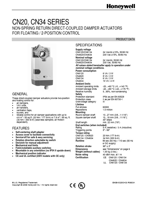
® U.S. Registered TrademarkEN0B-0320CH33 R0803ACopyright © 2008 Honeywell Inc. • All rights reservedCN20, CN34 SERIESNON-SPRING RETURN DIRECT-COUPLED DAMPER ACTUATORS FOR FLOATING / 2-POSITION CONTROLPRODUCT DATAGENERALThese direct-coupled damper actuators provide two-position and floating control for: • air dampers, • VAV units, • air handlers, • ventilation flaps, • louvers, and• reliable control for air damper applications with up to4.6 m 2 / 50 sq.ft. (20 Nm / 177 lb-in) or 7.8 m 2 / 85 sq. ft. (34 Nm / 300 lb-in) (seal-less dampers; air friction-dependent).FEATURES• Self-centering shaft adapter• Access cover to facilitate connectivity • Service/off for safe & easy servicing • Rotation direction selectable by switch • Declutch for manual adjustment • Mechanical end limits• Field-installable auxiliary switches• Mountable in any orientation (no IP54 if upside down) • Mechanical position indicator•CE and UL certified (230V models with CE only)SPECIFICATIONSSupply voltageCN6120/CN6134 24 Vac/dc ±15%, 50/60 Hz CN4620/CN4634 230 Vac ±15%, 50/60 Hz Nominal voltage CN6120/CN6134 24 Vac/dc, 50/60 Hz CN4620/CN4634 230 Vac, 50/60 HzAll values stated hereinafter apply to operation under nominal voltage conditions. Power consumption CN6120 6 VA / 3 W CN4620 8 VA / 3 W CN6134 6 VA / 3 W CN4634 10 VA / 4 W Ambient limitsAmbient operating limits -20...+60 °C (-5...+140 °F) Ambient storage limits -40...+80 °C (-40...+175 °F) Relative humidity 5...95%, non-condensing SafetyProtection standard IP54 as per EN 60529 Protection class II as per EN 60730-1 Overvoltage category III Lifetime Full strokes 60000Repositions 1.5 million MountingRound damper shaft 10...27 mm (3/8...1-1/16") Square damper shaft 10...18 mm (3/8...11/16");45° steps Shaft length min. 22 mm (7/8") End switches (when included) Rating 5 A (resistive) / 3 A (inductive) Triggering points 5° / 85° Torque rating CN6120 / CN4620 20 Nm (177 lb-in) CN6134 / CN4634 34 Nm (300 lb-in) Runtime 95 sec (60 Hz) / 110 sec (50 Hzor DC supply)Rotation stroke 95° ± 3° Dimensions see "Dimensions" on page 6 Weight (without cables) 1.35 kg (3 lbs.) Noise rating 40 dBA max. at 1 mCertification CE CN6120 / CN6134 CN4620 / CN4634UL CN6120 / CN6134CN20, CN34 SERIES DAMPER ACTUATOR FOR FLOATING AND 2-POS CONTROLEN0B-0320CH33 R0803A 2MODELSModel # DescriptionCN6120A1002 20Nm,24Vac/Vdc, Floating/2-position control, Non-Spring Return, No feedback and without aux. Switch CN4620A1001 20Nm,230V,Floating/2-position control, Non-Spring Return, No feedback and without aux. SwitchCN6134A1003 34Nm,24Vac/Vdc, Floating/2-position control, Non-Spring Return, No feedback and without aux. Switch CN4634A1001 34Nm,230Vac, Floating control/2-position, Non-Spring Return, No feedback and without aux. SwitchProduct Identification SystemFig. 1. Product Identification SystemOPERATION / FUNCTIONSFig. 2. Setting units and control elementsLegend for Fig. 2:1 Self-centering shaft adapter2 Retainer clip3 Rotational angle scales (0...90° / 90...0°)4 Mechanical end limits5 Declutch button6 Anti-rotation bracket7 Function selection switch8 Access coverContents of PackageThe delivery package includes the actuator itself, parts 1 through 8 (see Fig.2), the anti-rotation bracket screws, and installation instruction.RUN MODESThe function selection switch (see Fig. 3) can be used to place the actuator into any one of three different modes: • Dir, floating/2-position control, cw run. • Service/Off, actuator stop running. • Rev, floating/2-position control, ccw run. 12 3 4 5 67 8CN20, CN34 SERIES DAMPER ACTUATOR FOR FLOATING AND 2-POS CONTROL3 EN0B-0320CH33R0803AFig. 3. Function selection switchPower-Off BehaviorIf power is removed, the actuator retains its position.Service/OffIf the function selection switch is set to the "Service/Off" position, all rotary movement is cancelled, and all control signals are ignored, thus allowing the actuator to be safely manually operated.Floating/2-Position Run ModeIf the function selection switch has been set to one of the two floating/2-position control settings (Dir or Rev) and theactuator is wired correspondingly (see A1 and A2) as soon as the operating power is applied, the actuator will run according to the power appliedTable 1 describes the behavior (stops, rotates CCW, orrotates CW) of the CN6120/CN6134 in relation to the control signals (switch "open" or "24Vac/dc") applied to terminals 3 and 4, the function selection switch setting, and the manner in which the actuator is wired (either for floating mode: see A1, or for 2-position mode: see A2).Table 1. Behavior of CN6120/CN6134 Control signal at Function selection switchWiringterm. 3 term. 4 Dir Service/Off Revopen open stops stops stopsopen 24Vac/dc CCW stops CW Float. 24Vac/dc open CW stops CCW 24Vac/dc open CW stops CCW2-pos.24Vac/dc 24Vac/dc CCW stops CWTable 2 shows the same actuator behavior as Table 1, but for CN4620/CN4634 (230Vac models).Table 2. Behavior of CN4620/CN4634 Control signal at Function selection switchWiring term. 3 term. 4 Dir Service/Off Rev open open stopsstops stops open 230Vac CCW stops CW Float. 230Vac open CW stops CCW230Vac open CW stops CCW2-pos.230Vac 230Vac CCW stops CWSleep ModeWhen actuator reaches end stop or any obstacles blocking its running, it will fall into sleep mode automatically. Actuator willperiodically start up and try to resume running, which will save energy significantly through whole service life.Position IndicationThe hub adapter indicates the rotation angle position by means of the rotational angle scales (0...90° / 90...0°) provided in the actuator plate (see Fig. 4).Fig. 4. Position indicationManual AdjustmentI MPORTANTTo prevent equipment damage, you must remove power or set the rotation direction switch to the "Service/Off" position before manual adjustment.After removing power or setting the rotation direction switch to the "Service/Off" position, the gear train can be disengaged using the declutch button, permitting the actuator shaft to be manually rotated to any position.Limitation of Rotation StrokeTwo adjustable mechanical end limits (adjustable in 5° increments) are provided to limit the angle of rotation as desired (see Fig. 5).Fig. 5. Mechanical end limits The mechanical end limits must be securely fastened in place.It is important that they properly mesh with the rotational angle scales when the screws are tightened.Internal End SwitchesNOTE: Applicable to models with internal switches only.CN20, CN34 SERIES DAMPER ACTUATOR FOR FLOATING AND 2-POS CONTROLEN0B-0320CH33 R0803A 4The internal end switches are set to switch from "common" to "normally open" at angles of 5° and 85°, respectively, from the totally counterclockwise position.-Fig. 6. Internal end switch triggering pointsINSTALLATIONThese actuators are designed for single-point mounting.I MPORTANTIn order to prevent equipment damage, you mustremove power or set the rotation direction switch to the "Service/Off" position before manual operation.Mounting InstructionsAll information and steps are included in the installation instructions supplied with the actuator.Mounting PositionThe actuators can be mounted in any position (no IP54 if mounted upside down; see Fig. 7). Choose a mounting posi-tion permitting easy access to the actuator's cables and controls.Fig. 7. Mounting for IP54Mounting Bracket and ScrewsIf the actuator is to be mounted directly on a damper shaft, use the mounting bracket and screws included in the delivery package.Self-Centering Shaft AdapterThe self-centering shaft adapter can be used for shafts having various diameters (10...27 mm [3/8...1-1/16"]) and shapes (square or round).In the case of short shafts, the shaft adapter may be reversed and mounted on the duct side.Stroke Limitation with Mechanical End LimitsThe mechanical end limits enable the stroke to be limited from 0...90° in increments of 5°.WiringConnecting to the Power SupplyIn order to comply with protection class II, the power source of 24 V actuators must be reliably separated from the network power supply circuits as per DIN VDE 0106, part 101.Access CoverTo facilitate wiring the actuator to the controller, the access cover can be detached from the actuator.I MPORTANTRemove power before detaching the access cover. Once the access cover has been removed, please take care to avoid damaging any of the parts now accessible.Fig. 8. Access cover (models with internal switches)Depending upon the model, the access cover may have one or two terminal strips, including a layout with a description for each of the terminals.Fig. 9. Actuator with access cover removed(models with internal switches)CN20, CN34 SERIES DAMPER ACTUATOR FOR FLOATING AND 2-POS CONTROL5 EN0B-0320CH33 R0803AWiring diagramsA1 CN6120,CN4620CN6134,CN4634 FLOATINGA2 CN6120,CN4620CN6134,CN4634 2-POSA3 END SWITCHS(models with switch only)NOTE: Internal end switches S1 and S4 must be connected to the same power source. Below 2 tables summarize the information presented in the preceding wiring diagrams.WiringModelsTerminalFloating 2-position2 common ┴/─ common ┴/─3 24V ~/+ (clockwise) 24V ~/+ CN6120,CN6134 supply and signal lines(must be equipped with spark suppressors)4 24V ~/+ (counterclockwise) 24V ~/+ control signal 2 common ┴/─ common ┴/─ 3 230Vac (clockwise) 230Vac CN4620,CN4634 supply and signal lines(must be equipped with spark suppressors) 4 230Vac (counterclockwise) 230Vac control signalConnecting cableTerminal Description S1 common S2 normally closed CCW (left) 5° S3 normally open S4 common S5 normally closed end switches (models with internal switches only)CW (right) 85°S6 normally openOPTIONAL ACCESSORIESAuxiliary Switch KitOrder no.: SW2The auxiliary switches are field-installable parts providing two SPDT freely-adjustable switches.CN20, CN34 SERIES DAMPER ACTUATOR FOR FLOATING AND 2-POS CONTROLManufactured for and on behalf of the Environmental and Combustion Controls Division of Honeywell Technologies Sàrl, Ecublens, Route du Bois 37, Switzerland by its Authorized Representative:Automation and Control SolutionsHoneywell International Inc. Honeywell (Tianjin) Limited 1985 Douglas Drive North 66, BaiHe Road, TEDA Golden Valley, MN 55422 Tianjin, 300457,P.R.C.EN0B-0320CH33 R0803ADIMENSIONS。
哈尔滨明快机电科技有限公司 PCIe2011绝对式编码器采集卡产品手册说明书

绝对式编码器采集卡PCIe2011产品手册TEL/FAX:0451-******** 16534616699 Email:***************************目录1 板卡说明 (1)1.1 板卡介绍 (1)1.2 规格参数 (2)1.3 软硬件支持 (3)1.4 环境要求 (3)1.5 配套附件 (3)1.5.1 连接电缆 (4)1.5.2 端子台 (4)1.5.3 连接示例 (6)2 安装方式 (6)3 引脚定义 (9)3.1 DB37接口引脚分配 (9)3.2 DB9接口引脚分配 (9)3.3 DB37接口引脚定义 (10)4 编程说明 (11)4.1 驱动安装 (11)4.2 windows下编程函数 (11)4.3 RTX操作系统编程说明 (11)4.4 数据协议 (12)5 装箱清单 (13)6 注意事项 (13)TEL/FAX:0451-******** 16534616699Email:***************************网址:1 板卡说明1.1 板卡介绍PCIe2011是开放高速串行总线BISS-C的接口卡,适用于Renishaw绝对式测角、测距传感器和工控机的接口,是一种快速多功能,多通道同步的PCI-Express总线接口板。
同时兼容EnDat2.1及SSI接口。
该板卡应用范围广泛,在恶劣的工业环境中表现出高精度和高可靠性。
该产品具备以下技术特点:1)采用FPGA技术,同步接收最多5个绝对式测角、测距传感器的角度、位移输出信号,将其处理后传输给计算机;2)精确的时基以及动态采样补偿专利技术保证了采样的高可靠性;3)传感器线长自动补偿技术,在EMC条件适宜时,可以将采样周期稳定在40.4µs,达到现有绝对式读数头的极限;4)高速电磁隔离技术;5)采样精度为20ns,利用动态采样计时技术,实时产生同步、高品质角速度、角加速度、线速度和线加速度信号,将大幅度提升伺服控制系统的控制品质;6)采用高速PCIe总线接口,硬件插槽可采用PCIe-X1/PCIe-X4/ PCIe-X8/PCIe-X16;7)主DMA高速传输技术,5通道同步数据传输到内存中时间低于3µs;8)兼容MFC+RTX技术,便于用户在Windows下实现丰富接口和界面管理。
hs100m1-n伺服驱动器说明书

hs100m1-n伺服驱动器说明书
1.将静叶置手动状态,使用电磁阀完全关闭静叶,按手操器F1键,此时手操器屏幕上有“确定传感器新零点”字样,按回车键确认。
2.将静叶置手动状态,使用电磁阀完全开启静叶,按手操器F2键,此时手操器屏幕上有“确定传感器新量程”字样,按回车键确认。
3.同时按下手操器shift和F1键即F5键,此时手操器屏幕上有“设定K值”字样。
设置K 值为1。
此时将静叶置手动状态,使用伺服阀控制静叶,在静叶开度设置框中打入不同数字,现场观测静叶应该可以动作。
如果静叶不动作,请将K值设定为-1。
K值只能为1,不放同时按上下键可以将光标左右移动。
单按上下键可以改变光标所在位的数字。
PMM人工电源网络商品说明书

The AMN - Artificial Mains Network, also known as LISN - Line Impedance Stabilization Network is the ancillary device intended for repeatable and accurate measurement of the disturbance voltage that an EUT (Equipment Under T est) may inject into the power line or mains.This is obtained by providing well known impedance value and phase response across the frequency range of the test.L1-150M and L1-150M1 are a single-path LISN (Line Impedance Stabilization Network) designed to be easily used for conducted disturbances measurements according to different standards for Automotive and ISM (Industrial, Scientific, Medical) applications.Selecting the standard is as fast as the turn of a rotary switch located on the rear panel.PMM Artificial Mains Networks provide robust and stable m echanical construction, high quality electric components, easy and perfect grounding, solid input and output power connections. They can be used in conjunction with any EMI receiver or spectrum analyzer and offer features required for safe, repeatable and accurate measurements.Multi-standard Single-path LISNProvided Features•Powering the EUT•EUT termination to a standardizedimpedance respect to the reference ground •Coupling the measuring receiver to the disturbance generated by the EUT•Decoupling the measuring receiver from unwanted RF signals from the power lineMain Features•L1-150M: 100 kHz to 200 MHz frequency range •L1-150M1: 10 kHz to 400 MHz frequency range •Multi standard design •150 A max output current •Suitable also for DC lines•Large baseplate for optimal grounding •Robust, compact construction •Screw terminals for safe wiring•Meets the requirements of several standards including CISPR 16-1-2, CISPR 25, ISO 11452-2/4/5,ISO 7637-2, MIL-STD-461F, DO-160, ED-14GProvided by: (800)404-ATECAdvanced Test Equipment Rentals®Frequency range Continuous rated output currentMax. output current @ 45 °C Max. permissible operating voltagesEUT supply frequency range Equivalent circuit RF output connector EUT connectionLine input connection Ground connectionOperating temperature Storage temperature Dimensions (W x H x D)WeightReceiversLISNRFI Filters• 7010/00: EMI receiver 150 kHz to 1 GHz • 7010/01: EMI receiver 9 kHz to 1 GHz • 7010/02: EMI receiver 9 kHz to 30 MHz • 7010/03: EMI receiver 9 kHz to 3 GHz • 9010: EMI receiver 10 Hz to 30 MHz • 9010F: EMI receiver 10 Hz to 30 MHz• 9010/03P: EMI receiver 10 Hz to 300 MHz • 9010/30P: EMI receiver 10 Hz to 3 GHz •9010/60P: EMI receiver 10 Hz to 6 GHz• L2-16B: single phase AMN, 16 A • L3-32: 4 lines, 3-phase AMN, 32 A • L3-64: 4 lines, 3-phase AMN, 63 A• L3-64/690: 4 lines, 3-phase AMN, 63 A • L3-100: 4 lines, 3-phase AMN, 100 A • L3-500: 4 lines, 3-phase AMN, 500 A • L1-500: single phase AMN, 500 A•L2-D: Delta LISN for telecom, 2 A, 150 Ω• FIL-L2-16F: single phase RFI filter, 16 A • FIL-L2-24M: single phase RFI filter, 24 A • FIL-L3-32M: 3-phase+neutral RFI filter, 32 A •FIL-L3-70M: 3-phase+neutral RFI filter, 70 A100 kHz to 200 MHz L1-150M, L1-150M1Multi-standard Single-path LISNOrdering Information:L1-150M - L1-150M1 Artificial NetworkIncludes: Operating Manual, RF Cable, N-BNC adapter, Calibration CertificateOptional accessories:SBRF4: RF switching boxAutomatic (in conjunction with PMM receivers) andmanual switching of up to four single-path AMN. Internal 50 Ohm terminations and switchable 150 kHz high-pass filter. Low insertion loss.Max. operating frequency: 108 MHz.L 1150-F E N -40704 - S p e c i fi c a t i o n s s u b j e c t t o c h a n g e s w i t h o u t p r i o r n o t i c eSPECIFICATIONSRelated Products•Electrical safety and presence of ground protection relays do require the installation of properly rated insulating transformer(s) between mains power line and AMN line inputs.•High mains noise may require the installation of properly rated mains filters to reduce the level of unwanted signals.Sales Office:Via Leonardo da Vinci, 21/2320090 Segrate (Milano) - ITALY Phone: +39 02 2699871Fax: +39 02 26998700E-Mail:**************************Internet: www.narda-sts.itHeadquarter:Via Benessea, 29/B17035 Cisano sul Neva (SV) - ITALY Phone: +39 0182 58641Fax: +39 0182 586400L1-150ML1-150M110 kHz to 400 MHz100 A150 A 600 Vdc 300 Vac DC to 440 Hz (5 μH+0/1 Ω)//50 Ω N female, 50 Ω Screw terminal M10 Screw terminal M10 2x Screw terminal M10-10 to +45 °C -25 to +70 °C 230 x 105 x 410 mm5 kg。
伊玛产品类别

18~36 VDC
PNP NO/NC,NPN NO/NC
4~20 mA,0~10 V
可
PA1108
智慧型
7 LED
内螺纹
G 1/4
400 bar
四线
18~36 VDC
PNP NO/NC,NPN NO/NC
4~20 mA,0~10 V
可
PA1109
智慧型
7 LED
内螺纹
G 1/4
2 bar
四线
18~36 VDC
200
60
M12
接插件
N
Y
N
IP67
否
IA0031
齐平
brass
10~36VDC
1
两线
NO
DC PNP/NPN
200
60
M12
接插件
N
Y
N
IP67
否
IA0032
齐平
brass
10~36VDC
1
两线
NC
DC PNP/NPN
200
60
M12
接插件
N
Y
N
IP67
否
IA0033
非齐平
brass
10~36VDC
可
TA1099
智慧型
7 LED
内螺纹
M18 X 1.5
-40~150°C
四线
20~30 VDC
PNP NO/NC,NPN NO/NC
4~20 mA,0~10 V
可
产品类别
压力变送器(模拟量输出)
压力变送器(开关量输出)
订货号
功能
显示
牙口形式
布斯曼熔断开关和电流保护器目录说明书

O L ET ES E E N EW DI S CO NN EC TS W I T CH ES CA TA L OG12-17-98SB98107Rev. AForm No. BDF Page 1 of 2 BIF Doc #1121BDF60J6BDF100JT6Catalog Symbols*:BDF60J6, BDF100JT6Ampere Rating: 60 to 100 AmperesVoltage Rating: 600 VoltsAgency Approvals:UL Listed, Guide WPZX, File E155129CSA Certified, File 58077M9IEC 947-1General Information:Bussmann fused disconnect switches are UL 98/CSA 22.2 No. 4 devices. This makes them suitable for use on service equipment, panel boards, switchboards, industrial control equipment, motor control centers, etc.*Catalog symbol is for switch only. Handles and shafts are ordered separately.Fuse Maximum Horsepower RatingType200V208V240V480V600V BDF60J6J1515153040 BDF100JT6J†2525304050†Class J fuses are standard. If 600V Class T fuses are desired, us BDTA1 ponents:HandlesGripNEMA Length Padlock-Defeat-Catalog Style Type Color(Inches)Marking able able Number60-100A ( 0.24˝ x 0.24˝)Pistol1, 12Blk 3.15Off/On Yes Yes BDH20 Pistol1, 3R, 12Blk 2.36Off/On Yes Yes BDH50 Pistol4, 4X Blk 2.36Off/On Yes No BDH57 Terminal Lug Kits - Kit Includes 6 LugsAmp Rating Wire Size Wire Type Kit Catalog Number 100#14 - 2/0Cu/Al BDTL24200#6 - 300 kcmil Cu/Al BDTL25400#2 - 600 kcmil Cu/Al BDTL26600 & 800(2) #2 - 600 kcmil Cu/Al BDTL27ShaftsMounting Depth**Shaft Length Catalog Number60 - 100 Amps ( 0.24˝ x 0.24˝)5.50 - 8.50 5.90BDS1508.00 - 11.008.26BDS21011.00 - 14.0011.41BDS29013.75 - 16.7514.17BDS36016.54 - 19.6916.93BDS430**Mounting depth is measured from outside panel door to mounting plate of disconnect. Shaft can be cut to desired length.Accessories:Fuse Covers and Terminal Shrouds (line-side)Switch Type Fuse Covers Terminal Shrouds Amp Fuse Catalog Catalog Rating Type Voltage Number Number60J600V BDFC60J Not Required 100J or T600V BDFC100BDTSF1 Auxiliary Contacts - F60 through F100Switch Aux. Contact 1 N.O. & 1 N.C. 2 N.O. & 2 N.C. Amp Rating Amp Rating Voltage Catalog Number Catalog Number 606250BDAUX7BDAUX81006250BDAUX7BDAUX8E Form No. BDF Page 2 of 2BIF Doc #112112-17-98SB98107Rev. AThe only controlled copy of this BIF document is the electronic read-only version located on the Bussmann Network Drive. All other copies of this document are by definition uncontrolled. This bulletin is intended to clearly present comprehensive product data and provide technical information that will help the end user with design applications. Bussmann reserves the right, without notice, to change design or construction of any products and to discontinue or limit distribution of any products. Bussmann also reserves the right to change or update, without notice, any technical information con-tained in this bulletin. Once a product has been selected, it should be tested by the user in all possible applications.60 Amps100 AmpsDimensional Data。
Parker Hannifin I-Force Ironless ML18线性电动机产品介绍说明书

Contact Information: Parker Hannifin Corporation Electronic Motion and Controls Division 5500 Business Park DriveRohnert Park, CA 94928phone: 800 358-9070email:**************************.com /emc The ML18 incorporates the I-ForceI-beam shape with overlappingwindings allowing for high powerdensity, improved heat removal, andadded structural stiffness.In addition, the ironless linear motordesign has no attractive forces allowingfor zero cogging, rapid accelerations,and easy installation.Ironless Advantages• No attractive force betweenforcer and magnets make it safeand easy to install• Ironless forcer produces zerocogging for smooth operation• Ironless forcer means light weightand high rates of acceleration• Air gap between forcer andmagnets is forgiving allowing foreasy installationML18 I-Force Linear MotorsML18 Features• Smallest ironless motor available— saves valuable space• Extremely efficientoverlapping winding design for maximum force density • Optimized for operation between 24 to 80 VDC • Internal hall effects and thermal protection decreases carriage length • Low profile, compact design — cross-section just 35 mm x 18 mm• Peak forces to 50 N • Single-piece, ultra-compact folded magnet track eliminates all unnecessary material Dual rows of magnetsVacuum encapsulated ironlesscoil with I-beam shape U-Shaped magnet trackNon I-beam (T shaped)coil with larger pro le size,less thermal ef ciency and less rigidityActs as heat sink/adapter plateDual rows of magnetsI-beam DesignConventional DesignI-beam shaped coil for lower pro le,better thermal ef ciency and higher structural stiffnessML18 I-Beam Design AdvantageParker’s I-beam shape provides very high forces in a compact package. In addition, the design is morethermally efficient than tradition ironless motor designs.• Highly efficient mounting tabs for hassle-free mounting • Two lengths of modular track provide unlimited travel, maximum flexibility• CE and RoHS ComplianceParker Hannifin Corporation • Electronic Motion and Controls Division • 800-358-9070 • /emc1) Initial winding temperature must be 60°C or less before Peak Current is applied2)@ 25°C ambient, 125°C winding temperature 3)±30%, Line-to-Line, inductance bridge measurement @1 Khz4)Total motor torque per peak of the sinusiodal amps measured in any phase, ±10%5)The distance from the leading edge of a north pole to the leading edge of the next north pole 6)Measured Line-to-Line, ±10% 7)Value is measured peak of sine wave 8)Measured with a 0.76 mm gapML18 I-Force Linear MotorsSpeed-Force PerformanceParker Hannifin Corporation • Electronic Motion and Controls Division • 800-358-9070 • /emcParker Hannifin Corporation • Electronic Motion and Controls Division • 800-358-9070 • /emcCoil Dimensions — mm (in)Side MountingTop MountingMotor Phase and Hall LeadsParker Hannifin Corporation • Electronic Motion and Controls Division • 800-358-9070 • /emcML18 I-Force Linear MotorsMagnet Track with Coil Dimensions — mm (in)ML18080ML181201 2 3 4 5 6 7ML18 – 1 E – NC – N1 S – 3 1 2 3 4 ML18 – 120 M – NOrder Example: Select options from each numbered field to create a complete model order code including motor coil and magnet track.ML18 Ordering InformationSeriesML18Mini Linear MotorCoil Size 2 2 Pole 3 3 Pole 5 5 Pole Mounting E Standard Cooling NC No CoolingSeries ML18Mini Linear MotorTrack Length08080 mm 120120 mm Modular M Standard Magnet Coating N Nickel CoatingModule Ready N1No Module, Internal Halls Winding S Series P Parallel Cable 1 1 Meter 33 MeterMotor CoilMagnet Track27.227.218.017.018.017.0Electronics ManufacturingThe mSR is an ideal positioning system for high throughput electronics manufacturing equipment, as it design combines high performance linear motor technology with a variety ofhigh resolution feedback devices for quick, precise placement of miniature components. The mSR also provides an extremely robust solution for electronics inspection systems, as its direct drive linear motor technology has been designed to stand the test of time.Life Sciences - Digital PathologyMiniature packaging, high precision performance, and quick settling times make the mSR an optimum solution for imaging instruments used in digital pathology. With limited wear components the mSR is a durable stage that will minimize the riskof machine downtime.Looking for a Super Small Submicron Linear Positioner?The new Parker mSR100 Series Positioners are driven by ML18 Linear MotorsThe new Parker mSR100miniature positioner incorporatesML18 linear motors into singleand multi-axis systems thatprovide the ideal solution forinstrument builders and otherapplications requiring extremelysmooth, submicron positioningcapabilities, in a compactpackage.The mSR100 has a 100 mmwide profile and is availablewith stroke lengths from 25to 500 mm. Maximum loadcapability is 12 kg (26.5 lb). ThemSR100 offers selectable levelsof linear encoder technologyconfigured to the applicationneed, including a BiSS-Cabsolute encoder for installationsrequiring continuous positionalinformation.Want more info?For complete mSR100 features, benefits and specifications, go to:/emcSemiconductor Handling andMeteorologyGiven the combination of itssuperior geometric performanceand miniature packaging, themSR series positioner is idealfor semiconductor handlingand metrology applications.Regardless of whether youexamining features on the microor nano-scale – the mSR can beadapted to meet the need withits wide array of encoder options.The mSR also offers a strokescalable mechanical solution withstandard designs up to 500 mm.Parker Hannifin Corporation • Electronic Motion and Controls Division • 800-358-9070 • /emcEM Sales OfficesCatalog PN: 82-032580-01 Issue Date: 2/14/2023© 2023 Parker Hannifin CorporationParker Hannifin Corporation Electronic Motion and Controls Div.5500 Business Park Drive Rohnert Park, CA 94928 USA /emc Tel: 800-358-9070Email:**************************.comML18 Series: Made in the USAAustraliaParker Hannifin (Australia) Pty Ltd.9 Carrington Road Castle Hill NSW 2154AustraliaTel: +61 (0) 2 9634-7777 Fax: +61 (0) 2 9634 3749BrazilParker Hannifin Ind. Com Ltda.Av. Lucas Nogueira Garcez 2181Esperança12325-900 Jacareí, SP Tel: 12 3954 5100Fax: 12 3954 5262Email: a ***************************CanadaParker Hannifin (Canada) Inc.160 Chisholm DrMilton, Ontario L9T 3G9 Tel: 905-693-3000 Fax: 905-876-1958Email:****************************ChinaParker Hannifin Motion & Control (Shanghai) Co., Ltd280 Yunqiao Rd. Jin Qiao Export Processing ZoneShanghai 201206, China Tel: (86-21) 50312525Fax: (86-21) 64459717FranceParker SSD Parvex 8 avenue du Lac B.P . 249F-21007 Dijon CedexTel: +33 (0) 3 80 42 41 40Fax: +33 (0) 3 80 42 41 23GermanyElectromechanical EuropeParker Hannifin GmbH & Co KG Robert-Bosch-Strasse 22 D-77656 Offenburg GermanyTel: +49 (0) 781 509 0Fax: +49 (0) 781 509 98176Email:********************IndiaParker Hannifin India Pvt. LtdAutomation Group-SSD Drives Div.133 & 151 Developed Plots Estate Perungudi, Chennai 600 096Tel: 044-4391-0799Fax: 044-4391-0700ItalyParker Hannifin SpA Via Gounod 120092 Cinsello Balsamo Milano, ItalyTel: +39 02 361081Fax: +39 02 36108400Email: ********************KoreaParker Hannifin Korea9th Floor KAMCO Yangjae Tower 949-3 Dogok 1-dong Gangnam-gu Seoul 135-860, Korea Tel: 82-2-559-0454Fax: 82-2-556-8187MexicoParker Hannifin de Mexico Eje uno Norte No.100Parque Industrial Toluca 2000 Toluca, CP 50100 México Tel: 52-722-275-4200Fax: 52-722-279-0316SingaporeParker Hannifin Singapore Pte Ltd 11, Fourth Chin Bee Road Singapore 619702Tel: (65) 6887 6300Fax: (65) 6265 5125/6261 4929TaiwanParker Hannifin Taiwan Co., Ltd No. 40, Wuchiuan 3rd Road Wuku Industrial ParkTaipei County, Taiwan 248ROCTel: 886 2 2298 8987Fax: 886 2 2298 8982ThailandParker Hannifin (Thailand) Co., Ltd.1265 Rama 9 RoadSuanluang, Bangkok 10250 ThailandTel: (66) 2 186 7000Fax: (66) 2 374 1645UKParker Hannifin Ltd.Tachbrook Park Drive Tachbrook Park Warwick CV34 6TUTel: +44 (0) 1926 317970Fax: +44 (0) 1926 317980USAParker Hannifin Electronic Motion and Controls Division 5500 Business Park DriveRohnert Park, CA 94928 USA Tel: 800-358-9070Email:**************************.com Parker Hannifin Electronic Motion and Controls Division 1140 Sandy Hill Road Irwin, PA 15642Tel: 800-358-9070Email:**************************.com。
PAH1008中文资料

THYRISTOR MODULEParameter ParameterConditions ConditionsMax Rated Max RatedValue ValueUnitRMS On-State Current I T(RMS)50Hz Half Sine Wave conditionTc=82°C222 ASurge On-State Current I FSM50 Hz Half Sine Wave,1PulseNon-Repetitive 2000 A I Squared tI 2t 2msec to 10msec 20000 A 2sCritical Rate of Turned-On Current di/dt V D =2/3V DRM , I TM =2•I O , Tj=125°CI G =200mA, di G /dt=0.2A/µs100 A/µsPeak Gate PowerP GM 5 WAverage Gate Power P G(AV) 1 W Peak Gate Current I GM 2 A Peak Gate VoltageV GM 10 V Peak Gate Reverse VoltageV RGM 5 V Operating JunctionTemperature Range Tjw -40 to +125°C Storage Temperature Range Tstg -40 to +125°C Isoration VoltageViso Base Plate to Terminals, AC1min 2000 VCase mountingM5 Screw 2.4 to 2.8Mounting torqueTerminalsFtor M5 Screw 2.4 to 2.8N •mValue per 1 ArmP AElectrical • Thermal CharacteristicsMaximum Value.CharacteristicsSymbol Test Conditions Min. Typ. Max.UnitPeak Off-State Current I DM V DM = V DRM, Tj=125°C 40 mA Peak On-State Voltage V TM I TM = 300A, Tj=25°C1.38V Tj=-40°C200Tj=25°C100Gate Current to TriggerI GTV D =6V,I T =1A Tj=125°C 50 mA Tj=-40°C4Tj=25°C2.5Gate Voltage to TriggerV GT V D =6V,I T =1A Tj=125°C2V Gate Non-Trigger VoltageV GDV D =2/3V DRM Tj=125°C0.25 V Critical Rate of Rise of Off-State Voltage dv/dt V D =2/3V DRM Tj=125°C 500 V/µs Turn-Off Time tq I TM =I O ,V D =2/3V DRMdv/dt=20V/µs, V R =100V-di/dt=20A/µs, Tj=125°C 100 µs Turn-On Time tgt 6 µs Delay Time td 2 µs Rise Timetr Tj=25°C, I TM =I T(RMS) V D =100V, I G =200mA di G /dt=0.2A/µs 4 µs Latching Current I L Tj=25°C 100 mAHolding Current I H Tj=25°C50 Rth(j-c)Junction to Case0.15Thermal Resistance *1Rth(c-f)Base Plate to Heat Sinkwith Thermal Compound0.1°C/WValue Per 1Arm *1: Value Per ModulePAT/PAH1008 OUTLINE DRAWING (Dimensions in mm)PATPAH。
NEMA PB-1.1 电路板应用指南说明书

—RQ/RL lighting panel Application guideInstallationConsult instructions NEMA PB-1.1 located in the circuit directory on the front door before installing this panelboard. If necessary, order replacement manual from supplier.Wiring guidelines (Cu or Al)• Use 60 °C or 75 °C ampacity sized wire on line and neutral and equipment ground terminals.• Standard wire sizes listed in this publication may be changed by using alternate terminal kits.• Refer to circuit breakers for allowable wiretemperature rating, wire size and tightening torque.• Neutral rated for 200% panelboard phase current option.• Suitable for nonlinear loads, 200% rated neutral, additional “Y” lugs provided for 200% neutral.Short circuit current ratingThe panelboard’s maximum short circuit interrupting rating in rms symmetrical amperes is equal to the lowest interrupting rating of any device installed, except as noted in the series rating listed in1TQC173100E0001, with integral or remote main circuit breaker or fusible switch installed upstream of the panelboard. Devices to be installed or replacement units shall be from the samemanufacturer, of the same type, and have equal or greater interrupting capacity.Maximum continuous loads on main or branch circuits shall not exceed 80% of the ratings of the listed circuit breakers. Branch breaker straps suitable for 180 A maximum.Tripped breakerIf the breaker trips, handle will be in intermediate position.Instructions to restore power 1. Move handle to OFF position.2. Then move handle to ON position.Seismic ratingMeets or exceeds the requirements according to IBC-2018Sds = 2.0 g, Ip = 1.5, for z/h = 1.0 in accordance with ICC-ES-AC156 2010Sds = 2.5 g, Ip = 1.5, for z/h = 0.0 in accordance with ICC-ES-AC156 2010Polybag contentsA polybag of goods supplied with every panelboard interior contains:• Arc flash label• 1TQC173100E0001 series ratings, wiring diagrams and circuit directory • Series rating sticker• Front installation instructions • ANSI PB1 documentation• Circuit numbering stickers (1–84)• Front and shield mounting screws—01 RQ lighting panel —02 RL lighting panel—01—02—Torque—Tightening torqueApplies to line, neutral and equipment ground terminal Slotted screw Internal hexAWG wireLb-InHex sizeLb-In Min Max Min Max14–1032353⁄16108120 836401⁄4180200 6–441455⁄16240275 3–2/045503⁄83303751⁄2450500—Torque values for hardwareScrew size Torque (in-lbs) #4 Steel16 #10 Plastic16 #8 Cu/Al/steel24 #10–32 Cu/Al/steel32 1⁄4–20 Al/<0.150 thick Cu44 1⁄4–20 0.150 thick Cu60 5⁄16–18 Cu/Al/steel110 3⁄8–16 Cu/Al/steel220 1⁄2–13 Cu/Al/steel220—Lug kits—Lug kits for panelboardsRatingPressure lug kit Crimp lug kit Pressure lug kitCat.no.WirerangeAl/CuCat.no.WirerangeAl/CuCat.no.Wire rangeCu only 125 A MLA16–350MLT14-300MLR14–350 225 A MLA21/0–250MLT22/0–500MLR21/0–600400 A Standard— MLA414–600MLT41500–750(Cu only)MLR411/0–600Oversize— MLA623/0–800(main)and4–600(neutral)––––600 A Standard— MLA614–500––MLR611/0–600—Crimp toolsWire Crimp tool Up to #6–1000 kcmil Cuand #5–750 kcmil AlBurndy tool Y644HS—Neutral lug ZHoles Wire size — Cu/Al Large2/0–14 SmallNo. 4–14Arc fault label included with all interiors to be applied by electrical contractor.Interrupting ratings — molded case circuit breakersMolded case circuit breakers UL listed interrupting ratings in kARMS symmetrical AC voltsConstruction Frame Trip range(amps)Pole Ac120120/240240480Y/277480600HQ frame THQB 15–70 1120/240 1010– – – –THQL 15–125 2120/240 – 10– – – –15–100 2, 3 240 – –10 – – –THQL-AF15–20 1120/240 – 10– – – –THQL-DF15–20 1120 – 10– – – –THQL-GF15–30 1, 2 120/240 – 10– – – –THQL-HID 15–20 1, 2 120/240 – 10– – – –THQB-GF 15–30 1, 2 120/240 – 10– – – –THQB-HID 15–20 1, 2 120/240 – 10– – – –TXQB 15–30 1, 2 120/240 – 65– – – –HHQ frame THHQB15–701 120/240 – 22 22–––15–100 2120/240– 2222 – – –15–100 3240 – – 22 – – –THHQL15–125 2120/240 – 22– – – –15–100 2240 – –22 – – –15–100 3240 – –22 – – –THHQL-AF 15–20 1120/240 – – – – – –THHQL-DF 15–20 1120 22– – – – –THHQL-GF 15–30 1120/240 – 22 – – – –THHQL-HID 15–20 1, 2 120/240 – 22 – – – –THHQB-GF 15–30 1120/240 – 22 – – – –THHQB-HID 15–20 1, 2 120/240 – 22 – – – –Formula A2A2A12–2252, 3240 – –10 – – –A2N 12–225 2, 3 240 – – 25 – – –Tmax® XT XT1H 15–125 3480 – – 100 – – –XT1S 15–125 3480 – – 65 – – –XT4H 25–250 3480– – 150–––XT4L 25–250 3480 – – 200 – – –XT4S 25–250 3480 – – 100 – – –XT5H250–400and450–6003480 – –150 – – –XT5L250–400and450–6003480 – –200 – – –XT5S250–400and450–6003480 – –100 – – –XT6H 600–800 3480 – –200 – – –XT6S 600–800 3480 – –100 – – –XT6N 600–800 3480 – –65 – – –¹ Not current limiting breaker typeCircuit breaker terminals (Cu-Al)FramePoles²Cat. no.Wire Cu-Al (unless otherwise specified)Standard Current limiting /high interrupting Per lug RangeTHQB, TXQB, THHQB, THQL, THHQL, TXQL –1,2,3Fixed to breaker terminal1(15–30 A) #14–4 Cu or #12–4 Al,(35–100 A) #14–10 Cu or #12–1/0 AlXT1–31SDA075837R1³1Cu Al 1x10⁻²/0 AWG XT4–250 A–31SDA075865R1³1Cu Al 1x3/0 AWG–350 kcmil⁴XT4 (<250 A)–31SDA075861R1³1Cu Al 1x4 AWG–300 kcmil XT5–31SDA113066R1³2Cu Al 2x2/0 AWG–500 kcmil XT5 (750 kcmil)–31SDA115948R12500 kcmil – 750 kcmil⁵XT6–31SDA113070R1³3Cu Al 3x2/0 AWG–400 kcmil XT6 (750 kcmil)–31SDA115968R12500 kcmil – 750 kcmil⁵A2–31SDA069983R1³(3-pole – 3 pcs lug)1Cu 1x1 AWG-250 kcmilAl 1x2/0 AWG–300A2–21SDA069982R1³(2-pole – 2 pcs lug)1Cu 1x1 AWG-250 kcmilAl 1x2/0 AWG–300² 3-pole XT breakers can be used in 2-pole applications³ Kit contains 3 pcs lug⁴ External solution: lugs to be mounted on EF terminals supplied in the kit⁵ T he lug kit will come with 2 sets of cable set screws. One is for 600 kcmil and smaller cable and the other is for cable greater than 600 kcmil. Follow the instructions that are included with the kit. If you are upgrading the existing lugs to the 750 kcmil lugs, the customer, AHJ (authority having jurisdiction) and/or inspector will need to make sure the panel is compliant with NEC and UL cable bending space. ABB is not responsible for the addition of these lugs in existing panels.—Wiring spaceTypical panelboardFront view with trim removedTypical front with concealed hinges and trim adjusting screws Surface mounting — add 1⁄4" to inside box dimensionsFlush mounting — add 1 1⁄2" to inside box dimensions Typical box—Minimum wiring space, from end of lug to box wall, in inchesMainrating inampsMain lugs only,to end wallFrametype MountingMain circuit breakerPhase lugNeutrallug PhaselugNeutrallugTo sidewall (20"wide box)To endwall125 AMLO,100 Amainbreaker66XT1Horizontal5–6225 A1212XT4, A2Vertical–612 400 A1511⁵FG, XT5Vertical–1511⁵600 A1511⁵XT5Vertical–16–800 A⁶1511⁵XT6Vertical–18–⁵ To side wall⁶ Box width is 30 and 7.81 deep—Wiring space — branch circuit breakersBranch circuitdevices Frame No. of polesMinimum wiring spaces to side wall (20" wide box)Double branched bolt-on devices THQL, THHQL,THQB, THHQB1, 2, 3 6.5"Horizontalsubfeeds singlebranch mountedA2, XT1, XT42, 3 5.5"—EnclosuresPanel sizeBoxFront cat. no.⁹Cat. no.⁷Size inches⁸0–25.5AB25B25.5AF25F,S 28.5–31.5AB31B31.5AF31F,S 34.5–37.5AB37B37.5AF37F,S 40.5–43.5AB43B43.5AF43F,S 46.5–49.5AB49B49.5AF49F,S 52.5–55.5AB55B55.5AF55F,S 57.5–64.5AB64B64.5AF64F,S 67.5–76.5AB76B76.5AF76F,S⁷ B suffix provides blank end walls. Order K suffix for end walls with knockouts.⁸ Standard boxes are 20 wide by 5.81 deep.⁹ Flush fronts are 1⁄ larger than box. Surface fronts are ⁄ larger.—Front optionsDescription Cat. no. suffix10 Front hinged to box D Yale 5116 with Rosette Lock Y Corbin 15767 lock L 75 key lock E Corbin 60 key lock J Quarter-turn lock T Door-within-a-door11P Stainless steel12S 30" wide W Nameplate N Screw-on nameplate U Metal directory M10 Add to base front catalog number.11C onsists of two lockable doors—one over panel interior and one over box wiring gutters. Yale locks not available.¹² Flush only. Available with C and N options.—Box optionsDescription Cat. no. suffix13 Painted box P 30" wide14 W NEMA 3R/12/4S/4X 3 or 4 NEMA 3RX door-in-door 3M NEMA 4X (316 stainless steel) 4S¹³ Add to base box product number.¹⁴ Includes field installable gutter barrier.—Permanent circuit number kitsDescription Cat. no. 1–48 APN48 43–84 APN84 85–126 APN126—Stainless steel enclosuresDimensions (inches) Cat. no.H W D UL standard CSA labeled25.5206AB254S AB254AS 25.5308AB254DWS AB254DWAS 31.5206AB314S AB314AS 31.5308AB314DWS AB314DWAS 37.5206AB374S AB374AS 37.5308AB374DWS AB374DWAS 43.5206AB434S AB434AS 43.5308AB434DWS AB434DWAS 49.5206AB494S AB494AS 49.5308AB494DWS AB494DWAS 55.5206AB554S AB554AS 55.5308AB554DWS AB554DWAS 64.5206AB644S AB644AS 64.5308AB644DWS AB644DWAS 76.5206AB764S AB764AS 76.5308AB764DWS AB764DWAS—AccessoriesField-installed kits/replacement parts—Filler plates Breaker typeCat. no.THQB/THHQB/THQL THHQL/TEY TQLFP1FBTEDFP1—End wall kitsField installed. 1 each, for standard 20" w x 5.81" d boxes. Type Cat. no.Blank ABEW2KnockoutABEW2—Equipment grounds—AEBG —AEIG —ASPGIBC—AEBGC —AEIGCItem DescriptionWire rangeCat. no.Metalequipment groundBonded#14-#8 Cu, #12-#8 Al (small holes); #14-#4 Cu, #6-#4 Al(large holes)TGL2Extruded bonded#14-#8 Cu, #12-#8 Al (small holes); #14-#4 Cu, #6-#4 Al(large holes)EGS12Aluminum equipment groundExtruded bonded (1) #6-350 MCM AEBG Extruded isolated (2) #6-250 MCMAEIG Main lug#14-#8 Cu, #12-#8 Al (small holes); #14-#4 Cu, #6-#4 Al(large holes)TGL2Copper equipment groundBonded#14-#8 Cu, #12-#8 Al (small holes); #14-#4 Cu, #6-#4 Al(large holes)TGC2Extruded bonded#14-#8 Cu, #12-#8 Al (small holes); #14-#4 Cu, #6-#4 Al(large holes)AEBGCExtruded isolated (1) #4-350 kcmil AEIGC Insulated isolated(1) #6-250 kcmilASPGIBC—Bonding kits DescriptionCat. no.For split and load end neutral 343L886G16For 225 A horizontal neutrals343L886G13225 A horizontal neutral to convert 3W to 4WASP225HNCP 125/225 A horizontal neutral conversion from service entrance to non-service entranceASPHNCPSENOT125/225 A horizontal neutral to convert from non-service entrance to service entranceASPHNCPSEInstallation and maintenance kitOrder catalog number PROCARE. Kit includes:• (5) filler plate hardware kits • (9) bus stud nuts • (5) MLA1 filler plates • (2) 225 A phase barriers • (2) feed-thru barriers• (1) 400/600 A phase barrier• (50) directory cards/rating books • (50) circuit number strips (1–48)• (50) circuit number strips (43–84)• (5) standard locks and keys • (50) deadfront screws• (10) RQ/RE front hardware kits • (10) RD front hardware kits • (50) service disconnect labels • (50) main labels—Parts DescriptionCat. no.Directory card139C5612P3Replacement lock with standard key 569B737P1Replacement lock with GE75 key 569B737P2Additional keys for above lock 569B737P5Circuit numbering strips 1–48569B806G1Circuit numbering strips 49–84 569B806G2Circuit numbering strips 85–126569B806G3Adhesive backed lamicoid nameplate 3⁄4 x 3315A7190P1Metal directory card holder 139C5491G1Directory card holder139C5491P4Delta hi-leg conversion kit,to add B-phase plug on AL panelsAPHBL Bolt-on RE/RQ panelsAPHBQ NEMA 3R/12 tamper-proof tork screw kitNEMATRX 2-pole to 3-pole TQD conversion kitASP2PTQD3P 2-pole to 3-pole conversion kit for horizontal subfeed ASP2PTFJ3P RD 25 to 65 kAIC barrier kit ASP25AD65KA1Service entrance kit ASPSERENT 2-wire relay kitASP2WRelay Yale lock kit ASPYALE47Corbin lock kitASPCORBNTEU12–3 pole TQD mechanical interlock TQDFM1RQ/RL/RE rail bracket ASPAQLEBKT Front flush adjust kitASPFLUSHADJ RE front-mounting kit 139C5720G3RQ/RL front-mounting kit 139C5720G6RD front-mounting kit139C5728G9Front hinge-to-box mounting kit 139C5700G6Front extension mounting kit139C5700G111T Q C 173100E 0003 r e v B - 06.2023—We reserve the right to make technical changes or modify the contents of thisdocument without prior notice. With regard to purchase orders, the agreed particulars shall prevail. ABB Inc. does not accept anyr esponsibility whatsoever for potential errors or possible lack of information in this document.We reserve all rights in this document and in the subject matter and illustrations contained therein. Any reproduction, disclosure to third parties or utilization of its contents – in whole or in parts – is forbidden without prior written consent of ABB Inc. C opyright© 2023 ABB All rights reserved—ABB Inc.305 Gregson Drive Cary, NC 27511—Box extensionsBolts to box with or without end wall in place. Extensions can be combined to obtain lengths greater than 18 and 24 inches.Box width and depth BoxmountingBox extension length (inches)Cat. no.20 x 5.81Flush9 ABX2509F 18 ABX2518F 24ABX2524F Surface9 ABX2509S 18 ABX2518S 24 ABX2524S 37 ABX2537S 43 ABX2543S 49 ABX2549S 55 ABX2555S 64 ABX2564S 76ABX2576S 30 x 5.81Flush 18 ABX3518F 24 ABX3524F Surface18 ABX3518S 24 ABX3524S 30 x 7.81Flush 18ABX3718F 24ABX3724F Surface18 ABX3718S 24ABX3724S—Box extension covers only 10 covers per kit Description Cat. no.9 covers surface ASPABX09S 9 covers flush ASPABX09F 18 covers surface ASPABX18S 18 covers flush ASPABX18F64 to 76 covers surface ASPABX20S 64 to 76 covers flushASPABX20F—SpecificationsPanelboards and branch breakers meet or exceed the following standards and specifications:• National Electrical Code — Article 384• UL 67 panelboards: UL 50 cabinets and boxes. UL 943 GFCI • UL 489 molded case circuit breakers. UL 98 fusible switches • cUL listing for ReliaGear™ lighting panelboards• CSA listing for ReliaGear non-service entrance panelboards • International Building Code Seismic Zone 3 and 4• California Building Code Seismic Zone 4• NEMA PB1• Federal Specifications — Panelboards, W-P-115c. Type 1 — Circuit breaker equipped• Class 1 — Panelboards Class 2 — Load centers • Molded case circuit breakers, WC-375B/GEN. — Fusible switches, W-S-865cBoxes• Galvaneal painted and 316 stainless steel offerings• Blank end walls are standard; knockouts are available when specified with NEMA 1 enclosures only• Boxes furnished with provisions for ground bus as standard Fronts• Finished in ANSI-61 gray polyester powder coat paint• Equipped with corrosion-resistant Valox combination catch and lock door latch (doors over 48" high provided with 2 latches)• Equipped with concealed hinges and trim adjusting screws • Directory holder permanently mounted to doorPanels• Dead-front construction• Interiors are factory assembled on rigid steel frames• Metal gauges in accordance with UL and NEMA standards• Solderless, anti-turn main lugs suitable for copper or aluminum wires are front removable and branch straps are silver-plated copper fully rated at 100 amperes• Main bus is aluminum with copper branch connections unless otherwise specified• Main disconnect device is identified when supplied, and numbers are provided for branch circuits• Interior base assemblies are Noryl and provide breaker mounting and busbar insulationPublications E-DET-465Certification of seismic compliance 1TQC173100E0003RQ/RL lighting panel application guide1TQC173100E0001Lighting panels rating labels, wiring diagrams andcircuit directory。
上海华明用说明书

HMK7控制器使用说明书HM0.460. 13021.概述1.1 主要用途HMK7控制器(以下简称控制器)作为一种自动控制装置通过有载分接开关附带的电动操作机构来控制有载分接开关的切换操作,实现有载调压的自动控制控制器可显示开关切换操作状态及分接位置。
控制器有着完善的接口可输出BCD码(触点容量:0.5A 120V AC 或1A 28VDC)及输入远动信号(无源触点),实现有载分接开关的通过触点的远端监视与控制,也可通过RS485 通讯接口与上位机通讯进行遥控、遥信,实现有载分接开关的无触点的远端监视与控制。
1.2适用范围控制器主要用来驱动我公司生产的SHM-1电动操作机构。
2.工作环境2.1周围空气温度不低于-10℃,不高于+40℃;2.2空气相对湿度不大于85%;2.3海拔高度不大于2500m;2.4无显著振动和冲击场所;2.5无爆炸危险的介质,周围介质不含有腐蚀金属及破坏绝缘的气体或导电尘埃;2.6无雨雪侵蚀的场所。
3.外形及安装尺寸3.1外形尺寸见下图;4.1.1电源电压:220V AC 4.1.2额定频率:50Hz 4.3显示参数4.3.1分接位置:1-355.3原理简介分接位置经隔离后为CPU读取并显示并输出分接位置的BCD码,同时进行极限位置的判别和中间位置的超越。
MCU读取经隔离后的其他控制信号控制电动操作的动作程序。
进行指令选择后,控制器可接受的指令有三种输入形式:第一,选择“本地”,指令从控制器面板输入;第二,选择“远控”指令从控制器后面接线端子输入;第三,选择“电操”,指令从SHM-1电动操作机构面板输入,也可通过SHM-1附带的遥控器输入。
输入“1-N”或“N-1”指令后,控制器输出单一驱动信号,SHM-1完成从一个工作位置变换到相邻的工作位置,SHM-1分接变换指示轮指针转动一圈,完成一次操作后自动停止。
如果操作过程中控制器断电,恢复供电后控制器继续完成前一次中断的操作。
HLP-A100系列通用型矢量变频器使用说明书

系列
1 1 2 2 3 4 4 5 6 9 9 9 9 9 11 11 11 12 13 17 18 18 18 19 20 22 23 24 25 48 48
系列
6.2 第01组参数:负载/电动机
ห้องสมุดไป่ตู้
52
6.3 第02组参数:制动功能
61
6.4 第03组参数:设定值/加减速
63
6.5 第04组参数:极限/警告设置
43
代表电压等级为三相380V;
P20
代表IP等级为IP20;
X
不带交流电抗器;
A
带交流电抗器;
X
不带制动单元;
B
带制动单元;
X
不带直流电抗器;
D
带直流电抗器;
1
附带有数码管显示且带电位器的操作面板;
C
PCB上涂有三防漆;
X
工厂保留;
0
销往国内;
1
销往国外;
XXX
工厂保留;
VXXX
表示软件版本号,如V235表示版本号为V2.35;
内部故障或保护。 ● 请勿自行拆装更改变频器内部连接线或零部件。 ● 严禁私自改装,更换控制板及零部件,否则有触电,发生爆炸等
危险。 ● 请防止儿童或无关人员接近变频器。
1.2 送电中
危险
● 送电中绝不可插拔变频器上的任何连接器(操作面板除外),以 避免变频器损坏并造成人员伤亡。
● 送电前请盖好面盖,以防触电,造成人身伤害。
HLP-A100系列使用说明书
系列
危险
● 实施配线前,请务必切断电源。 ● 请将变频器安装于金属类等不可燃材料上,以防止发生火灾。 ● 请不要把变频器安装在含有易燃易爆气体的环境里,否则有引
布斯曼系列ATM插线保护器数据表说明书

ATM blade fusesCatalog symbol•ATM-_DescriptionA range of UL ® Listed fast-acting miniature blade fuses for automotive and low-voltage circuits.Ratings• Volts: 32 Vac/dc • Amps: 2 to 30 A •Interrupting rating: 1 kAAgency information• UL Listed, Guide FHXT , File AU169•ISO 8820-3 / JASO D612 / SAE J2077 and J1171 ignition protectionMaterials• Silver-plated zinc terminals and element •Polyamide housing with UL 94 HB flammabilityratingEnvironmental•Operating temperature range -40°C to +80°C, 95% RH non-condensing•Storage temperature range -5°C to +35°C or lower, 85% RH non-condensingBasic catalog numbersATM-2Gray ATM-15Blue ATM-3Violet ATM-20Y ellow ATM-4Pink ATM-25Clear ATM-5Tan ATM-30GreenATM-7-1/2Brown* Available only in traditional and bulk pack.Packaging codesReload ATM-(amp)RLD*10 fuses in a polybag Retail pack BP/ATM-(amp)-RP 5 fuses in a blister card Value pack VP/ATM-(amp)-RP 25 fuses in a clamshell packBulk packBK/ATM-(amp)500 fuses in a carton* Not available for the 4 amp ATM fuses.Dimensions — inOperating @ 23°C*135%0.75 sec 600 sec 160%0.25 sec 50.0 sec 200%0.15 sec 5.0 sec 350%0.04 sec 0.5 sec 600%0.02 sec0.1 sec* Fuse characteristics may vary according to the conditions under which they are used. Fuse derating with change in ambient temperature: -0.15% / 1°C.Features• Halogen free and RoHS compliant •Test points on fuse housing speeds troubleshooting•Industry standard color coded by amp ratingT ypical applications• Automotive•Low voltage control circuitsRecommended fuse holders, add-a-circuit and fuseclipsHHH additional fused circuit on a block 32V/10A 5”/#16HHLInline fuse holder with cover 32V/20A 2x4”/#16HHM Inline fuse holder with cover 32V/30A 2x4”/#12HHU Water resistant inline fuse holder with cover32V/30A 2x4”/#12ATM-FHIDIndicating inline fuse holder with cover 32V/20A 2x4”/#161A5778**PCB fuse clip 32V/15A —1A5779**PCB fuse clip with nylon base32V/15A—** See data sheet no. 2131 for details.HALOGENHF FREEATM blade fusesTechnical Data 2048Effective January 2019Eaton and Bussmann are valuable trademarks of Eaton in the US and other countries. Y ou are not permitted to use the Eaton trademarks without prior written consent of Eaton.Eaton1000 Eaton Boulevard Cleveland, OH Bussmann Division 114 Old State Road Ellisville, MO 63021United States/bussmannseries© 2019 EatonAll Rights Reserved Printed in USAPublication No. 2048 — BU-SB15054January 2019Follow us on social media to get thelatest product and support information.For Eaton’s Bussmann series product information,call 1-855-287-7626 or visit:/bussmannseriesThe only controlled copy of this data sheet is the electronic read-only version located on the Eaton network drive. All other copies of this document are by definition uncontrolled. This bulletin is intended to clearly present comprehensive product data and provide technical information that will help the end user with design applications. Eaton reserves the right, without notice, to change design or construction of any products and to discontinue or limit distribution of any products. Eaton also reserves the right to change or update, without notice, any technical information contained in this bulletin. Once a product has been selected, it should be tested by the user in all possible applications.Time-current characteristic curves — average meltT i m e i n s e c o n d sCurrent in amps1 A15 A10 A7-1/2 A5 A 4 A 3 A 2 A20 A 25 A30 A 1109876543210010000.010.1110,000100010010Electrical characteristics249.7 m Ω140 mV 329.6 m Ω140 mV 423.8 m Ω136 mV 5 A 16.7 m Ω112 mV 7-1/211.1 m Ω112 mV 107.82 m Ω106 mV 15 4.93 m Ω99 mV 20 3.48 m Ω95 mV 25 2.58 m Ω92 mV 302.12 m Ω86 mV。
伊玛产品类别
10~36VDC
2
三线
NO
DC PNP
200
40
2
PVC
带线
N
Y
N
IP67
否
非齐平
brass
10~36VDC
2
三线
NO
DC NPN
200
40
2
PVC
带线
N
Y
N
IP67
否
齐平
brass
10~36VDC
1
三线
NO
DC PNP
200
40
2
PVC
带线
N
Y
N
IP67
否
非齐平
brass
10~36VDC
产品类别
订货号
感应面
材质
工作
电压
感应
距离mm
电气
设计
输出
负载
电流
外观
尺寸mm
连接
方式
防护
等级
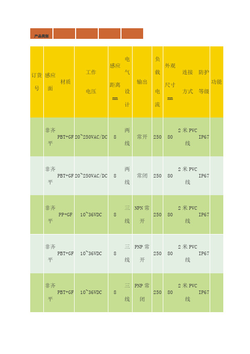
功能
非齐平
PBT+GF
20~250VAC/DC
8
两线
常开
250
80
2米PVC线
IP67
非齐平
PBT+GF
20~250VAC/DC
8
两线
常闭
250
80
2米PVC线
IP67
非齐平
PP+GF
10~36VDC
8
三线
NPN常开
PNP NO/NC,NPN NO/NC
可
智慧型
7 LED
内螺纹
G 1/4
10 bar
四线
- 1、下载文档前请自行甄别文档内容的完整性,平台不提供额外的编辑、内容补充、找答案等附加服务。
- 2、"仅部分预览"的文档,不可在线预览部分如存在完整性等问题,可反馈申请退款(可完整预览的文档不适用该条件!)。
- 3、如文档侵犯您的权益,请联系客服反馈,我们会尽快为您处理(人工客服工作时间:9:00-18:30)。
DescriptionThis family of SMT LEDs is packaged in the industry standard PLCC-2 package. These SMT LEDs have high reliability performance and are designed to work under a wide range of environmental conditions. This high reliability feature makes them ideally suited to be used under harsh interior automotive as well as interior signs application conditions.To facilitate easy pick & place assembly, the LEDs are packed in EIA-compliant tape and reel. Every reel will be shipped in single intensity and color bin, except red color, to provide close uniformity.These LEDs are compatible with IR solder reflow process. Due to the high reliability feature of these products, they can also be mounted using through-the-wave soldering process.The super wide viewing angle at 120˚ makes these LEDs ideally suited for panel, push button, or general backlighting in automotive interior, office equipment, industrial equipment, and home appliances. The flat top emitting surface makes it easy for these LEDs to mate with light pipes. With the built-in reflector pushing up the intensity of the light output, these LEDs are also suitable to be used as LED pixels in interior elec-tronic signs.Features• Industry standard PLCC-2 package • High reliability LED package• High brightness using AlInGaP and InGaN dice tech-nologies • Available in full selection of colors • Super wide viewing angle at 120˚• Available in 8 mm carrier tape on 7 inch reel (2000 pieces)• Compatible with both IR and TTW soldering processApplications• Interior automotive– Instrument panel backlighting – Central console backlighting – Cabin backlighting • Electronic signs and signals – Interior full color sign – Variable message sign• Office automation, home appliances, industrial equipment– Front panel backlighting – Push button backlighting – Display backlightingHSMx-A10x-xxxxx PLCC-2Surface Mount LED IndicatorData SheetCAUTION: HSMN,M,K and E-A10x-xxxxx LEDs are Class 2 ESD sensitive. Please observe appropriate precau-tions during handling and processing. Refer to Avago Application Note AN-1142 for additional details.Package Dimensions(ANODE MARKING FOR AlGaAs DEVICES)TOP MOUNTREVERSE MOUNTNOTE: ALL DIMENSIONS IN MILLIMETERS.Device Selection GuideRedPart Number Min. Iv (mcd) Typ. Iv (mcd) Max. Iv (mcd) Test Current (mA) Dice Technology HSMS-A100-J00J1 4.0 15.0 - 20 GaP HSMS-A100-L00J1 10.0 15.0 - 20 GaP HSMS-A100-H70J2 .0 - 8.0 10 GaP HSMS-A100-J80J2 5.0 - 15.5 10 GaP HSMH-A100-L00J1 10.0 15.0 - 20 AlGaAs HSMH-A100-N00J1 25.0 50.0 - 20 AlGaAs HSMH-A100-L70J2 12.5 - 2.0 10 AlGaAs HSMH-A100-M80J2 20.0 - 62.0 10 AlGaAs HSMH-A100-P 0J1 40.0 - 100.0 20 AlGaAs HSMC-A100-J00J1 4.0 100.0 - 20 AlInGaP HSMC-A100-Q00J1 6 .0 100.0 - 20 AlInGaP HSMC-A100-R00J1 100.0 140.0 - 20 AlInGaP HSMC-A101-S00J1 160.0 220.0 - 20 AlInGaP HSMZ-A100-T00J1 250.0 50.0 - 20 AlInGaP HSMC-A100-P 0J1 40.0 - 100.0 20 AlInGaP HSMC-A101-R80J1 125.0 - 95.0 20 AlInGaP HSMZ-A100-S80J1 200.0 - 620.0 20 AlInGaPRed OrangePart Number Min. Iv (mcd) Typ. Iv (mcd) Max. Iv (mcd) Test Current (mA) Dice Technology HSMJ-A100-Q00J1 6 .0 100.0 - 20 AlInGaP HSMJ-A101-S00J1 160.0 200.0 - 20 AlInGaP HSMV-A100-T00J1 250.0 50.0 - 20 AlInGaP HSMJ-A100-Q 0J1 6 .0 - 155.0 20 AlInGaP HSMJ-A100-R40J1 100.0 - 15.0 20 AlInGaP HSMJ-A101-R80J1 125.0 - 95.0 20 AlInGaP HSMV-A100-S80J1 200.0 - 620.0 20 AlInGaPOrangePart Number Min. Iv (mcd) Typ. Iv (mcd) Max. Iv (mcd) Test Current (mA) Dice Technology HSMD-A100-J00J1 4.0 15.0 - 20 GaP HSMD-A100-L00J1 10.0 15.0 - 20 GaP HSMD-A100-J7PJ2 5.0 - 12.5 10 GaP HSMD-A100-K4PJ2 6. - 20.0 10 GaPHSML-A100-Q00J1 6 .0 100.0 - 20 AlInGaP HSML-A101-S00J1 160.0 220.0 - 20 AlInGaP HSML-A100-Q7PJ1 80.0 - 200.0 20 AlInGaP HSML-A100-R7PJ1 125.0 - 15.0 20 AlInGaP HSML-A101-R8WJ1 125.0 - 95.0 20 AlInGaPDevice Selection Guide, continuedYellow/AmberPart Number Min. Iv (mcd) Typ. Iv (mcd) Max. Iv (mcd) Test Current (mA) Dice Technology HSMY-A100-J00J1 4.0 12.0 - 20 GaP HSMY-A100-L00J1 10.0 12.0 - 20 GaP HSMY-A100-J 5J2 4.0 - 10.0 10 GaP HSMY-A100-K45J2 6. - 20.0 10 GaP HSMA-A100-Q00J1 6 .0 100.0 - 20 AlInGaP HSMA-A101-S00J1 160.0 220.0 - 20 AlInGaP HSMU-A100-S00J1 160.0 20.0 - 20 AlInGaP HSMA-A100-Q 5J1 6 .0 - 155.0 20 AlInGaP HSMA-A100-R45J1 100.0 - 15.0 20 AlInGaP HSMA-A101-R8WJ1 125.0 - 95.0 20 AlInGaP HSMU-A100-S4WJ1 160.0 - 500.0 20 AlInGaPYellow GreenPart Number Min. Iv (mcd) Typ. Iv (mcd) Max. Iv (mcd) Test Current (mA) Dice Technology HSMG-A100-J02J1 4.0 18.0 - 20 GaP HSMG-A100-K72J2 8.0 - 20.0 10 GaP HSME-A100-M02J1 16.0 70.0 - 20 AlInGaP HSME-A100-N82J1 0.0 - 100.0 20 AlInGaPEmerald GreenPart Number Min. Iv (mcd) Typ. Iv (mcd) Max. Iv (mcd) Test Current (mA) Dice Technology HSMG-A100-H01J1 2.5 8.0 - 20 GaP HSMG-A100-G 1J2 1.6 - 4.0 10 GaP HSMG-A100-H41J2 2.5 - 8.0 10 GaP HSME-A100-L01J1 10.0 40.0 - 20 AlInGaP HSME-A100-M PJ1 16.0 - 40.0 20 AlInGaPGreenPart Number Min. Iv (mcd) Typ. Iv (mcd) Max. Iv (mcd) Test Current (mA) Dice Technology HSMM-A101-R00J1 100.0 200.0 - 20 InGaN HSMM-A100-S00J1 160.0 50.0 - 20 InGaN HSMM-A101-Q7PJ1 80.0 - 200.0 20 InGaN HSMM-A101-R7PJ1 125.0 - 15.0 20 InGaN HSMM-A101-R8PJ1 125.0 - 95.0 20 InGaN HSMM-A100-S8PJ1 200.0 - 620.0 20 InGaNDevice Selection Guide, continuedCyanPart Number Min. Iv (mcd) Typ. Iv (mcd) Max. Iv (mcd) Test Current (mA) Dice Technology HSMK-A101-R00J1 100.0 170.0 - 20 InGaNHSMK-A100-S00J1 160.0 280.0 - 20 InGaNHSMK-A100-S8WJ1 200.0 - 620.0 20 InGaNHSMK-A101-Q WJ1 6 .0 - 155.0 20 InGaNHSMK-A101-R4WJ1 100.0 - 15.0 20 InGaNBluePart Number Min. Iv (mcd) Typ. Iv (mcd) Max. Iv (mcd) Test Current (mA) Dice Technology HSMB-A100-J00J1 4.0 15.0 - 20 GaNHSMB-A100-J70J2 5.0 - 12.5 10 GaNHSMB-A100-K80J2 8.0 - 25.0 10 GaNHSMN-A101-N00J1 25.0 50.0 - 20 InGaNHSMN-A100-P00J1 40.0 70.0 - 20 InGaNHSMN-A101-N7YJ1 0.0 - 80.0 20 InGaNHSMN-A100-P8YJ1 50.0 - 155.0 20 InGaNNote:1. The luminous intensity, I v, is measured at the mechanical axis of the lamp package. The actual peak of the spatial radiation pattern may not be aligned with this axis.Part Numbering SystemHSM x1 - A x2 x x4 -x5x6 x7 x8x9Packaging OptionColor Bin SelectionIntensity Bin SelectDevice Specific ConfigurationPackage TypeLED Chip ColorAbsolute Maximum Ratings (T A = 25°C)Parameters HSMS/D/Y/G HSMH HSMC/J/L/A HSME HSMZ/V/U HSMM/K/B/N DC Forward Current[1] 0 mA 0 mA 0 mA[ ,4]20 mA[4] 0 mA[ ,4] 0 mA Peak Forward Current[2]100 mA 100 mA 100 mA 100 mA 100 mA 100 mA Power Dissipation 6 mW 60 mW 6 mW 48 mW 72 mW 114 mW Reverse Voltage 5 VJunction Temperature 110°COperating Temperature –55°C to +100°CStorage Temperature –55°C to +100°CNotes:1. Derate linearly as shown in Figure 4.2. Duty factor = 10%, Frequency = 1 kHz.. Drive current between 10 mA and 0 mA is recommended for best long term performance.4. Operation at current below 5 mA is not recommended.Electrical Characteristics (T A = 25˚C) Forward Voltage Reverse Voltage Reverse Voltage ThermalV F (Volts) @ I F = 20 mA V R @ 100 µA V R @ 10 µA Resistance Part Number Typ. Max. Min. Min. R θJP (°C/W)HSMS/D/Y/G 2.2 2.6 5 — 180HSMH 1.9 2.6 5 — 180HSMC/J/L/A/E 1.9 2.4 5 — 280HSMZ/V/U 2.2 2.6 5 — 280HSMB .9 4. — 5 280HSMM/K/N .44.05—5280Optical Characteristics (T A = 25˚C)ViewingLuminous PeakDominant Angle Luminous Intensity/ Wavelength Wavelength [1] 2 θ1/2[2] Efficacy ηv [3] Total FluxDiceλPEAK (nm) λD (nm) (Degrees) (lm/W) I v (mcd)/Φv (mlm) Color Part Number Technology Typ. Typ. Typ. Typ. Typ.Red HSMS-A100 GaP 6 5 626 120 120 0.45 HSMH-A100 AlGaAs 645 6 7 120 6 0.45 HSMC-A10x AlInGaP 6 5 626 120 150 0.45 HSMZ-A100 AlInGaP 6 9 6 0 120 155 0.45Red HSMJ-A10x AlInGaP 621 615 120 240 0.45OrangeHSMV-A100 AlInGaP 62 617 120 26 0.45Orange HSMD-A100 GaP 600 602 120 80 0.45 HSML-A10x AlInGaP 609 605 120 20 0.45Amber HSMY-A100 GaP 58 585 120 520 0.45 HSMA-A10x AlInGaP 592 590 120 480 0.45 HSMU-A100 AlInGaP 594 592 120 500 0.45Yellow HSMG-A100 GaP 565 569 120 590 0.45Green HSME-A100 AlInGaP 575 570 120 560 0.45Emerald HSMG-A100 GaP 558 560 120 650 0.45GreenHSME-A100 AlInGaP 566 560 120 610 0.45Green HSMM-A10x InGaN 52 525 120 500 0.45Cyan HSMK-A10x InGaN 502 505 120 00 0.45Blue HSMB-A100 GaN 428 462 120 65 0.45HSMN-A10xInGaN468470120750.45Notes:1. The dominant wavelength, λD , is derived from the CIE Chromaticity Diagram and represents the color of the device.2. θ1/2 is the off-axis angle where the luminous intensity is 1/2 the peak intensity.. Radiant intensity, I e in watts/steradian, may be calculated from the equation I e = I v /ηv , where I v is the luminous intensity in candelas and ηv is the luminous efficacy in lumens/watt.Figure 1. Relative intensity vs. wavelength.Figure 2. Forward current vs. forward voltage.Figure 3. Relative intensity vs. forward current.Figure 4. Maximum forward current vs. ambient temperature. Derated based on T J MAX = 110˚C, RθJA= 500˚C/W.current – InGaN devices.FORWARD VOLTAGE – V103035 F O R W A R D C U R R E N T – m A5201525Figure 4b. Maximum Forward Current Vs. Solder Point Temperature. Derated based on T J MAX = 110°C, RθJP= 180°C/W or 280°C/W.101520253035TEMPERATURE (°C)C U R R E N T - mA5101520253035TEMPERATURE (°C)C U R R E N T - m ACURRENT – mA460480540 D O M I N A N T W A V E L E N G T H – n mHSMx-A100 fig 5500470510490520530Figure 8a. Recommended SnPb reflow soldering profile.D E L T A V F (N O R M A L I Z E D A T 25°C )-0.3TEMPERATURE – °C0.50.40.20.10-0.2-0.10.3Figure 6. Forward voltage shift vs. temperature.Figure 8b. Recommended Pb-free reflow soldering profile.(Acc. to J-STD-020C)TIMET E M P E R A T U R ET E M P E R A T U R E – °CNote: For detail information on reflow soldering of Avago surfaceFigure 11. Tape leader and trailer dimensions.Figure 13. Reel dimensions.11Intensity Bin Select (X5X6) Individual reel will contain parts from one half bin only.X5Min I v BinX60 Full Distributionhalf bins starting from X514 4 half bins starting from X515 5 half bins starting from X517 half bins starting from X528 4 half bins starting from X529 5 half bins starting from X52 Intensity Bin LimitsBin ID Min. (mcd) Max. (mcd) G1 1.80 2.24G2 2.24 2.80H1 2.80 .55H2 .55 4.50J1 4.50 5.60J2 5.60 7.20K1 7.20 9.00K2 9.00 11.20L1 11.20 14.00L2 14.00 18.00M1 18.00 22.40M2 22.40 28.50N1 28.50 5.50N2 5.50 45.00P1 45.00 56.00P2 56.00 71.50Q1 71.50 90.00Q2 90.00 112.50 R1 112.50 140.00 R2 140.00 180.00 S1 180.00 224.00 S2 224.00 285.00 T1 285.00 55.00 T2 55.00 450.00 U1 450.00 560.00 U2 560.00 715.00 V1 715.00 900.00 V2 900.00 1125.00 Tolerance of each bin limit = ± 12%.Color Bin Select (X7)Individual reel will contain partsfrom one full bin only.X70 Full DistributionZ A and B onlyY B and C onlyW C and D onlyV D and E onlyU E and F onlyT F and G onlyS G and H onlyQ A, B, and C onlyP B, C, and D onlyN C, D, and E onlyM D, E, and F onlyL E, F, and G onlyK F, G, and H only1 A, B, C, and D only2 E, F, G, and H onlyB, C, D, and E only4 C, D, E, and F only5 A, B, C, D, and E only6 B, C, D, E, and F onlyColor Bin LimitsBlue Min. (nm) Max. (nm)A 460.0 465.0B 465.0 470.0C 470.0 475.0D 475.0 480.0Green Min. (nm) Max. (nm)A 515.0 520.0B 520.0 525.0C 525.0 5 0.0D 5 0.0 5 5.0Cyan Min. (nm) Max. (nm)A 490.0 495.0B 495.0 500.0C 500.0 505.0D 505.0 510.0Color Bin LimitsEmeraldGreen Min. (nm) Max. (nm)A 552.5 555.5B 555.5 558.5C 558.5 561.5D 561.5 564.5Orange Min. (nm) Max. (nm)A 597.0 600.0B 600.0 60 .0C 60 .0 606.0D 606.0 609.0E 609.0 612.0Red Orange Min. (nm) Max. (nm)A 611.0 616.0B 616.0 620.0Red Min. (nm) Max. (nm)Full DistributionTolerance of each bin limit = ± 1 nm.Amber Min. (nm) Max. (nm)A 582.0 584.5B 584.5 587.0C 587.0 589.5D 589.5 592.0E 592.0 594.5F 594.5 597.0YellowGreen Min. (nm) Max. (nm)E 564.5 567.5F 567.5 570.5G 570.5 57 .5H 57 .5 576.512Packaging Option (X 8X 9)Option Test Current Package Type Reel Size J1 20 mA Top Mount 7 inch J4 20 mA Top Mount 1 inch H1 20 mA Reverse Mount 7 inch H4 20 mA Reverse Mount 1 inch J2 10 mA Top Mount 7 inch J5 10 mA Top Mount 1 inch H2 10 mA Reverse Mount 7 inch H5 10 mA Reverse Mount1 inchFor product information and a complete list of distributors, please go to our website: Avago, Avago Technologies, and the A logo are trademarks of Avago Technologies Limited in the United States and other countries.Data subject to change. Copyright © 2007 Avago Technologies Limited. All rights reserved. Obsoletes AV01-0040EN AV02-0198EN - May 30, 2007Moisture SensitivityThis product is qualified as Moisture Sensitive Level 2a per Jedec J-STD-020. Precautions when handling this moisture sensitive product is important to ensure the reliability of the product. Do refer to Avago Application Note AN5 05 Handling of Moisture Sensitive Surface Mount Devices for details.A. Storage before use- Unopen moisture barrier bag (MBB) can be stored at <40°C/90%RH for 12 months. If the actual shelf life has exceeded 12 months and the HIC indicates that baking is not required, then it is safe to reflow the LEDs per the original MSL rating.- It is not recommended to open the MBB prior to assembly (e.g. for IQC).B. Control after opening the MBB- The humidity indicator card (HIC) shall be read im-mediately upon opening of MBB.- The LEDs must be kept at < 0°C / 60%RH at all time and all high temperature related process including soldering, curing or rework need to be completed within 672 hours.C. Control for unfinished reel- For any unuse LEDs, they need to be stored in sealed MBB with desiccant or desiccator at <5%RH.D. Control of assembled boards- If the PCB soldered with the LEDs is to be subjected to other high temperature processes, the PCB need to be stored in sealed MBB with desiccant or desic-cator at <5%RH to ensure no LEDs have exceeded their floor life of 672 hours.E. Baking is required if:- “10%” or “15%” HIC indicator turns pink.- The LEDs are exposed to condition of > 0°C / 60% RH at any time.- The LEDs floor life exceeded 672 hours.Recommended baking condition: 60±5°C for 20 hours.。