丰炜PLC VH 使用手册
LadderMast——丰炜PLC各种指令大全,仿三菱

码 变 换 及 定 时 器
170 171
D D
GRY GBIN
P P
BIN→GRY码变换 GRY码→BIN变换
高 速 处 理
D D D D
176 177 178
TFT TFH TFK
10mS 定时器 100mS 定时器 1秒 定时器
便 利 指 令
61 62 63 64 65 66 67 69 70
D D
P P P P P P P P P P P P P
2 进位浮点数比较 2 进位浮点数区域比较
四 则 及 逻 辑 运 算
23 24 25 26 27 28 29 30 31 32 33 34 35 36 37 38 39 40 41 42 43 44 45 46 47 48 49 50 51 52 53 54 55 56 57 58
224 225 226 228 229
D D
外 部 设 定 及 显 示
71 72 73 74 76 77 78 79
P
7段显示器解碼 7段显示器扫瞄输出 英文字母变换成ASCII码
D D
FROM TO
P P
ASCII码输出 特殊模块之BFM读出 特殊模块之BFM写入
230 232 233 234 236 237 238 240 241 242 244 245 246
浮 点 运 算
2进位浮点数→ 10进位浮点 数变换 10进位浮点数→ 2进位浮点 数变换 2 进位浮点数加算 2 进位浮点数减算 2 进位浮点数乘算 2 进位浮点数除算 2 进位浮点数开平方根 2进位浮点数 → BIN整数变 换 三角函数运算 SIN 三角函数运算 COS 三角函数运算 TAN
旋 转 及 位 移
E+H操作手册FTL51C
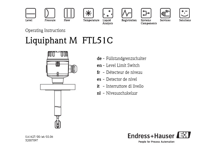
KA162F/00/a6/03.0652007097Operating InstructionsLiquiphant M FTL51Cde -Füllstandgrenzschalter en -Level Limit Switch fr -Détecteur de niveau es -Detector de nivel it -Interruttore di livello nl -Niveauschakelaarde-InhaltSicherheitshinweise 4Behandlung 6Geräte-Identifikation 8Verwendung 12Messeinrichtung 13Einbau 17Einstellungen 26Lichtsignale 30Anschluss 31Wartung 52Technische Daten 53Zubehör 54Fehlersuche 55Ersatzteile 63Reparatur 65Ergänzende Dokumentation 66"Achtung!= verboten;führt zu fehlerhaftem Betrieboder Zerstörung.en - ContentsNotes on Safety 4Handling 6Device Identification 8Application 12Measuring system 13Installation 17Setting-up 26Light signals 30Connections 31Maintenance 52Technical Data 53Accessories 54Trouble-shooting 56Spare parts 63Repair 65Supplementary Documentation 66"Caution!= forbidden;leads to incorrect operationor destruction.fr-SommaireConseils de sécurité 4Manipulation 6Dénomination 8Utilisation 12Ensemble de détection de niveau 13Montage 17Réglage 26Signaux lumineux 30Raccordement 31Entretien 52Caractéristiques techniques 53Accessoires 54Recherche de défauts 57Pièces de rechange 63Réparations 65Documentation complémentaire 66"Attention!= interdit; peut provoquerdes dysfonctionnementsou la destruction.es-IndiceNotas sobre seguridad 5Modo de empleo 6Identificación del equipo 8Aplicación 12Sistema de medida 13Montaje 17Ajuste 26Señales luminosas 30Conexiones 31Mantenimiento 52Datos técnicos 53Accesorios 54Identificación de fallos 58Repuestos 63Reparaciones 65Documentación suplementaria 66"Atención!= Prohibido; peligrode mal funcionamientoo de destrucción.it-IndiceNote sulla sicurezza 5Accorgimenti 6Identificazione dello strumento 8Applicazione 12Sistema di misura 13Montaggio 17Messa in servizio 26Segnali luminosi 30Collegamenti elettrici 31Manutenzione 52Dati tecnici 53Accessori 54Individuazione e eliminazionedelle anomalie 59Ricambi 63Riparare 65Documentazione supplementare 66"Attenzione!= Vietato; pericolodi malfunzionamentoo di distruzione.nl-InhoudVeiligheidsinstructies 5Behandeling 6Instrument- identificatie 8Toepassing 12Meetopstelling 13Inbouw 17Instellingen 26Lichtsignalen 30Aansluiting 31Onderhoud 52Technische gegevens 53Toebehoren 54Fout zoeken 60Reserve-onderdelen 63Reparatie 65Aanvullende documentatie 66"Opgelet!= verboden;leidt tot foutieve werkingof storing.de-SicherheitshinweiseDer Liquiphant M FTL51C darfnur als Füllstandgrenzschalter fürFlüssigkeiten verwendet werden.Bei unsachgemäßem Einsatzkönnen Gefahren von ihmausgehen.Das Gerät darf nur vonqualifiziertem undautorisiertem Fachpersonalunter strenger Beachtung dieserBetriebsanleitung,der einschlägigen Normen,der gesetzlichen Vorschriftenund der Zertifikate(je nach Anwendung)eingebaut, angeschlossen,in Betrieb genommen undgewartet werden.In der Gebäudeinstallation ist einNetzschalter für das Gerät leichterreichbar in dessen Nähe zuinstallieren.Er ist als Trennvorrichtung für dasGerät zu kennzeichnen.en-Notes on SafetyThe Liquiphant M FTL51C isdesigned for level limit detectionin liquids.If used incorrectly it is possible thatapplication-related dangers mayarise.The Liquiphant M FTL51Cmay be installed, connected,commissioned, operated andmaintained by qualified andauthorised personnel only,under strict observance ofthese operating instructions,any relevant standards,legal requirements, and,where appropriate, the certificate.Install an easily accessible powerswitch in the proximity of thedevice.Mark the power switch as adisconnector for the device.fr-Conseils de sécuritéLe Liquiphant M FTL51C doit êtreexclusivement utilisé commedétecteur de niveau pour liquides.Il peut être source de danger encas d’utilisation non conforme auxprescriptions.L’appareil ne doit être installé,raccordé, mise en service etentretenu que par un personnelqualifié et autorisé, qui tiendracompte des indications contenuesdans la présente mise en service,des normes en vigueuret des certificats disponibles(selon l’application).Installer un commutateur réseau àproximité immédiate de l’appareil,en veillant à ce qu’il soit facilementaccessible.Marquer ce commutateur commeprise de coupure de l’appareil.es-Notas sobre seguridadEl detector de nivel Liquiphant MFTL51C ha sido diseñado para ladetección de límite en fluidos.Su empleo inapropiado puederesultar peligroso.El equipo deberá ser montado,conectado, instalado y mantenidoúnica y exclusivamente porpersonal cualificado yautorizado, bajo rigurosaobservación de las presentesinstrucciones de servicio,de las normativas ylegislaciones vigentes,así como de los certificados(dependiendo de la aplicación).Instalar un interruptor de fácilacceso en las proximidades delequipo.Identificar el interruptor comodesconectador del equipo.it-Note sulla sicurezzaIl Liquiphant M FTL51Cè particolarmente studiato perl'impiego come soglia di livello inliquidi.Un'installazione non corretta puòdeterminare pericolo.Lo strumento può essere montatosolamente da personalequalificato ed autorizzato.La messa in esercizio e lamanutenzione devono rispettarele indicazioni di collegamento,le norme e i certificati di seguitoriportati.Installare un interuttore perl'alimentazione in prossimità deldispositivo.Marcare l'interuttore comedisconnessione del dispositivo.nl-VeiligheidsinstructiesGebruik de Liquiphant M FTL51Calleen als niveauschakelaar voorvloeistoffen.Indien niet correct gebruiktkunnen gevaarlijke situatiesontstaan.Het instrument alleen doorgekwalificeerd engeautoriseerd personeel lateninbouwen, aansluiten, in bedrijfnemen en onderhouden.Neem de instructies in dezeInbedrijfstellingsvoorschriften,de desbetreffende normen,de wettelijke voorschriften eneventuele certificaten in acht.Installeer een makkelijk bereikbarevoedingschakelaar in de nabijheidvan het instrument.Kenmerk de voedingschakelaarspecifiek voor het instrument.。
简单型PLC使用说明
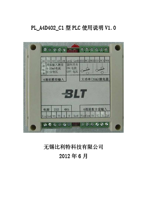
PL_A4D4O2_C1型PLC使用说明V1.0V1.0 无锡比利特科技有限公司无锡比利特科技有限公司2012年6月目录一、PLC产品特点 (3)二、PLC产品主要参数 (4)三、机械尺寸结构图 (5)四、接口定义 (6)五、接线方法 (8)1.电源接线方法 (8)2.232串口接线方法 (8)3.485接线方式 (8)4.数字开关量的接线方式 (9)4.1 内部电路 (9)4.2 无源输入 (10)4.3 有源输入 (10)5.模拟量的接线方式 (11)6.继电器的接线方式 (12)6.1 常开接点接灯的示例如下 (12)6.2 常闭接点接电机的示例如下 (12)6.3 常开接点闭合指示灯 (12)六、软件介绍 (14)1.调试前的准备 (14)2. 软件应用 (15)2.1 打开我公司PLC软件 (15)2.2 配置通讯接口 (16)2.3 验证通讯是否正常 (16)2.4 设定时间 (18)2.5 模拟量模式选择 (19)2.6 设备地址选择修改 (20)2.7 启动实时监控 (20)2.8 通道编辑 (21)2.9 排程设置 (22)2.10 清空设备内部逻辑 (24)七、协议介绍 (25)1.串口通讯参数 (25)2.协议格式定义 (25)2.1 命令码 (25)2.2 错误码 (26)2.3 寄存器地址及例子 (26)八、附件 (30)一、PLC产品特点产品特点严格按照工业控制标准设计RS485/RS232标准接口MODBUS_RTU标准协议控制可多模块485组网级联4路12位4-20mA(0-5V,可拨码选择)模拟量采集2路30A继电器输出,LED指示灯指示继电器闭合状态 4路光电隔离开关量输入采集(可拨码选择无源/有源) RTC时间控制可定时控制继电器打开/闭合可设置一次/工作日/每日循环控制可编程电平/模拟量输入触发控制可延时控制继电器打开/闭合心跳指示灯指示程序运行状态软件设定地址等参数标准工业导轨安装提供控制和编程示例程序.完全提供协议,同时,可按客户要求定制协议二、PLC产品主要参数特征 描述长: 115mm宽: 90mm机械特性高: 40mm重量:150g供电电源 11.5-12.5V,1A232通讯 9600bps通讯方式484通讯 9600bps电流型 4-20mA,12位ADC模拟量输入电压型 0-5V,12位ADC无源 12V,0.3A输出数字量输入有源 3.3V-24V输入继电器 30A/30VDC 250VAC逻辑存储量 10条温度范围 工作环境温度-30℃ — +85℃三、机械尺寸结构图四、接口定义Vin: 输入电源正极,直流电压11.5V-12.5V输入。
GE-PLC-使用手册

F1
I1
ADD INT
I2
Q
?????
?????
?????
减法运算
F2
I1
SUB INT
I2
Q
?????
?????
?????
乘法运算
F3
I1
MUL INT
I2
Q
?????
?????
?????
除法运算
F4
I1
DIV INT
I2
Q
?????
?????
?????
MATH mul
F3
Shift
>
| 10
| 4
0
1
0
0
0
0
Q1
(
)
Q2
(
)
I1
I1
I
2
Q2
CPU
输出地址%Q
输入地址%I
用户程序
数据储存 (%M,%R,...)
I
1
I
2
I
3
I
4
I
5
I
6
I
7
I
8
C
O
M
输入模块
输出模块
Q1
Q2
Q3
Q4
Q5
Q6
Q7
Q8
C
O
M
1
2
3
输入扫描
执行 程序
输出刷新
通讯服务
1
2
3
GE PLC 地址表示形式
外部地址
I2
OK
%I,%Q,%M,%T,%G 不能用于 REAL
Q
%I,%Q,%M,%T,%G, %R,%AI,%AQ,CONST
丰炜plc资料

M、VB及VH系列PLC程式编輯手册版本:2 版本日期:2007年11月前言本手册内容主要在說明M、VB及VH系列PLC之程式规劃。
關於可程式控制器的安装、配線、保養及安全注意事项,請参閱該系列可程式控制器之硬體說明書。
目録1.M、VB及VH系列PLC概論 (1)1-1PLC使用須知 (1)1-1-1 PLC(ProgrammableLogicController)可程式控制器的構成 (1)1-1-2 PLC的運轉及掃描時間 (1)1-1-3 PLC輸出入延遲 (2)1-1-4 PLC使用的記憶體 (2)1-1-5 PLC無法編寫程式的回路 (3)1-1-6雙重輸出 (3)1-2M系列P L C產品概要 (5)1-2-1 M系列PLC的主要特點 (5)1-2-2 M系列PLC功能規格 (6)1-2-3 M系列PLC機型一覽表 (7)1-3V B系列P L C產品概要 (9)1-3-1 VB系列PLC的主要特點 (9)1-3-2 VB系列PLC功能規格 (10)1-3-3 VB系列PLC機型一覽表 (11)1-4V H系列P L C產品概要 (13)1-4-1 VH系列PLC的主要特點 (13)1-4-2 VH系列PLC功能規格 (14)1-4-3 VH系列PLC機型一覽表 (15)1-5M、V B、V H系列P L C指令表 (17)1-5-1基本指令一覽表 (17)1-5-2應用指令表 (18)2.各種元件功能說明 (25)2-1元件一覽表 (25)2-1-1 M系列PLC元件一覽表 (25)2-1-2 VB系列PLC元件一覽表 (26)2-1-3 VH系列PLC元件一覽表 (27)2-2翰入繼電器X及翰出繼電器Y (28)2-2-1輸入繼電器 (28)2-2-2輸出繼電器 (28)2-2-3 M系列之輸出入繼電器編號 (28)2-2-4 VB系列之輸出入繼電器編號 (29)2-2-5 VH系列之翰出入繼電器編號 (30)2-3輔助繼電器M (31)2-4步進繼電器S (31)2-5計時器T (32)2-5-1一般計時器 (32)2-5-2積算型計時器 (32)2-5-3在副程式中使用計時器之注意事項 (33)2-5-4設定值的指定方法 (33)2-5-5計時器的詳細動作及精度 (33)2-6計数器C (34)2-6-116位元計数器 (34)2-6-232位元計數器 (35)2-6-3設定值的指定方法 (36)2-7高速計數器 (37)2-7-1單相高速計數器 (38)2-7-2雙相高速計數器 (39)2-7-3 AB相高速計數器 (40)2-7-4使用高速計數器之注意事项 (41)2-8資料暫存器D (42)2- 9 檔案暫存器D (43)2-9-1檔案暫存器的結構輿特性 (43)2-9-2檔案暫存器的讀出舆寫入 (44)2-9-3寫入檔案暫存器之注意事项 (45)2- 1 0 索引暂存器V 、Z (46)2- 1 1 指標P 、 I (47)2-11-1指標P (47)2-11-2中斷指標I (47)2- 1 2 数值系統 (48)2-13特殊繼電器及特殊暂存器 (51)2-13-1特殊繼電器一臂表 (51)2-13-2特殊暂存器一覽表 (54)2-13-3錯誤訊息說明 (57)2-13-4 VB系列多功能顯示幕 (59)2-13-5 VH系列錯誤碼顯示功能 (70)3.基本指分 (71)3- 1 基本指令一覽表 (71)3- 2 L D 、L D I 、A N D 、A N I 、O R 、O R I 、O U T 、E N D 指令 (73)3- 3 A N B 、O R B 指令 (74)3- 4 M P S 、M R D 、M P P 指令 (75)3- 5 M C 、M C R 指令 (76)3- 6 S E T 、R S T 指令 (77)3- 7 P L S 、P L F 指令 (77)3- 8 計時器、計数器的O U T 、R S T 指令 (78)3- 9 L D P 、L D F 、A N D P 、A N D F 、O R P 、O R F 、 I N V 指令 (79)3-10程式規劃時的注意事項 (80)3-10-1階梯圖轉换成指令碼 (80)3-10-2程式規劃技巧 (81)4.順序功能圖(SFC)及步進階梯圖 (83)4-1順序功能圖(SFC)解說 (83)4-1-1 SFC基本架構 (83)4-1-2 SFC基本組成單元 (83)4-1-3 SFC的狀態及動作 (84)4-1-4 SFC的型態 (84)4-2步進階梯指令 (85)4-3SFC與步進階梯圖的關係 (87)4-3-1單一流程之SFC及步進階梯圖 (87)4-3-2選擇性分歧及合流之SFC及步進階梯圖 (87)4-3-3業進式分歧及合流之SFC及步進階梯圖 (88)4-3-4跳躍之SFC及步進階梯圖 (88)4-3-5重複之SFC及步進階梯圖 (89)4-4較複雜的分歧、合流回路 (90)4-4-1虚擬状態 (90)4-4-2必須特别注意的分歧、合流 (91)4-5使用步進階梯指令編寫程式時之注意事項 (92)4-6與SFC相關的特殊繼電器及特殊暂存器 (92)5.應用指分的通則 (93)5- 1應用指令的格式 (93)5-2應用指令對資料的處理方式 (95)5-3使用索引暂存器V、Z修飾運算元 (96)5-4使用應用指令時之注意事項 (97)6.應用指分 (99)6-1應用指令一覽表 (99)6-2程式流程指令 (105)6-3比較及傳送指令 (113)6-4四則及邏輯運算指令 (123)6-5旋轉及位移指令 (131)6-6資料處理指令 (139)6-7高速處理指令 (151)6-8便利指令 (167)6-9外部設定及顯示指令 (179)6-10串列通訊指令 (191)6-11浮點運算指令 (205)6-12雜項指令 (219)6-13萬年曆及碼轉换指令 (227)6-14比較接點指令 (237)附録A.VB1系列之高速輸出入功能 (243)A-1 VB1之高速輸出功能 (243)A-1-1定位控制指令 (243)A-1-2定位控制程式例 (250)A-1-3 PLSY及PLSR脈波輸出指令 (252)A-2VB1之高速輸入功能 (255)A-2-1中斷插入方式之高速翰入功能 (255)A-2-2硬體高速計数器HHSC功能 (255)A-2-3硬體高速計数器之程式例 (257)B.通訊功能說明 (259)B-1通訊功能使用須知 (259)B-1-1通訊界面 (259)B-1-2通訊参數 (259)B-1-3通訊協定 (259)B-1-4形成通訊的基本要素 (259)B-1-5建置通訊系統的注意事項 (259)B-2通訊系統構成 (261)B-2-1 M系列PLC之通訊系統構成 (261)B-2-2 VB系列PLC之通訊系統構成 (263)B-2-3 VH系列PLC之通訊系統構成 (267)B-3通訊工作模式 (268)B-3-1 CP2之通訊工作模式選擇 (268)B-3-2 Computer Link(電腦連結) (269)B-3-3 EasyLink (272)B-3-4 CPU Link(CPU連結) (278)B-3-5 Parallel Link (282)B-3-6 MODBUS通訊 (284)B-3-7 MODEM通訊 (295)B-3-8 MODEM撥號 (297)B-3-9 Non Protocol(無通訊協定)通訊 (301)B-4VB-1COM串列通訊模組 (311)B-4-1模組介紹 (311)B-4-2外部配線 (311)B-4-3模組規格 (312)B-4-4緩衝記憶體BFM (313)B-4-5程式範例 (318)B-5 M、VB及VH系列通訊協定 (324)B-5-1通訊相關參數 (324)B-5-2通訊協定資料格式 (325)B-5-3通訊命令說明 (326)C.補充說明 (331)C-1新增指令 (331)1 . M 、VB 及VH 系列PLC 概論1- 1 PLC 使用須知1- 1- 1 PLC(Programmable Logic Controller)可程式控制器的構成圆1-11-1-2 PLC 的運轉及掃描時間PLC 的運算中心在程式處理中心,其運算過程如下所示:透過輸入界面將外界各種翰入元件ON/OFF 狀態讀入,业存放在資料記憶體中程式處理中心根據資料記憶體中之資料,及使用者所寫 成的程式,作成控制的結果,业將結果存回資料記憶體中X0X1Y0Y0使用者程式處理使用者程式Y20Y25M0將资料記憶體中存放運算結果的部份,經由翰出界面送到外界,驅動各種负载一個掃描時間 (Scan time)運算結果翰出外界狀態翰入M100M105掌上型書寫器或 程式書寫裝置 PC 規劃軟體使用者程式馬達程式處理中心極限開關 近接開關 光電開關指示燈電磁閥各種輸入元件電磁接觸器各種负载1-1-3 PLC 翰出入延遲●PLC翰入延遲由於PLC 的工作環境經常充滿各種雜訊及干擾源,為能正常工作PLC 經常在其翰入端利用光耦 合器隔離雜訊,芷在翰入回路加上雜訊滤除電路,通常會造成約10mS 的翰入信號延遲。
PLC驱动器操作手册
4-1 参数群组说明 .................................................................................................................... 27 4-2 参数机能表 ........................................................................................................................ 28
第五章 异常警报排除
5-1 异常警报说明 ...................................................................................................................... 53 5-2 异常排除对策 ...................................................................................................................... 54
2-3 控制信号标准接线图 ......................................................................................................... 21
3
2-3-1 位置控制(P Mode)接线图(Line Driver) ..................................................................... 21 2-3-2 位置控制(P Mode)接线图(Open Collector) ............................................................... 22 2-3-3 速度控制(S Mode)接线图 .......................................................................................... 23 2-3-4 转矩控制(T Mode)接线图 .......................................................................................... 24
plc控制系统设计的一般步骤
plc控制系统设计的一般步骤丰炜PLC说明资料1-PLC系统设计及选型方法在现代化的工业生产设备中,有大量的数字量及模拟量的控制装置,例如电机的起停,电磁阀的开闭,产品的计数,温度、压力、流量的设定与控制等,工业现场中的这些自动控制问题,若采用可编程控制器(PLC)可以轻松的解决,PLC已成为解决自动控制问题最有效的工具之一,越来越广泛的应用于工业控制领域中,本文简要叙述了PLC控制系统设计的步骤及PLC 的基本选型方法,供大家参考.一、可编程控制器应用系统设计与调试的主要步骤( 1 )深入了解和分析被控对象的工艺条件和控制要求这是整个系统设计的基础,以后的选型、编程、调试都是以此为目标的.a .被控对象就是所要控制的机械、电气设备、生产线或生产过程。
b .控制要求主要指控制的基本方式、应完成的动作、自动工作循环的组成、必要的保护和连锁等。
对较复杂的控制系统,还可将控制任务分成几个独立部分,这样可化繁为简,有利于编程和调试。
( 2 )确定 I/O 设备根据被控对象的功能要求,确定系统所需的输入、输出设备。
常用的输入设备有按钮、选择开关、行程开关、传感器、编码器等,常用的输出设备有继电器、接触器、指示灯、电磁阀、变频器、伺服、步进等.( 3 )选择合适的 PLC 类型根据已确定的用户 I/O 设备,统计所需的输入信号和输出信号的点数,选择合适的 PLC 类型,包括机型的选择、 I/O 模块的选择、特殊模块、电源模块的选择等。
( 4 )分配 I/O 点分配 PLC 的输入输出点,编制出输入 / 输出分配表或者画出输入 / 输出端子的接线图。
接着就可以进行 PLC 程序设计,同时可进行控制柜或操作台的设计和现场施工。
( 5 )编写梯形图程序根据工作功能图表或状态流程图等设计出梯形图即编程.这一步是整个应用系统设计的最核心工作,也是比较困难的一步,要设计好梯形图,首先要十分熟悉控制要求,同时还要有一定的电气设计的实践经验。
丰炜PLC以太网模块VB-ENET手册

從主機名稱下點滑鼠左鍵兩下:
按下 IP 設定 選擇使用下列的 IP 位址 編輯完成按 確定
主機名稱: PLC (可由客戶自訂) 操作模式:Server 通訊協定:Vigor UDP 連接阜編號:1000 串列通訊速率:19200 設定完成按確定
回上層
回主旨
副站設定:B 棟
在紅色框內按滑鼠左鍵兩下
2.PLC 與 PLC 連結採 Easy Link 通訊協定
主站 VB-ENET 通訊協定設定為 Vigor UDP 操作模式為 Client 副站 VB-ENET 通訊協定設定為 Vigor UDP 操作模式為 Server 副站與副站間通訊使用 RS-485 連接
3.人機介面透過 VB-ENET 與 Vigor PLC 通訊
選擇 Easy Link
回上層
回主旨
3.人機介面透過 VB-ENET 與 Vigor PLC 通訊
首先設定 VB-ENET 要先開啟 VBENETCFG.exe
VB-ENET RS-232 設定
按下讀取資料後如下圖:
從主機名稱下點滑鼠左鍵兩下如下圖:
主機名稱: 123(可由客戶自訂) 按下 IP 設定如下圖:
VB-ENET 通訊協定設定為 Modbus TCP 操作模式為 Server 人機介面通訊協定設定為 Modbus TCP/IP 4.VB-ENET 與 Visual SCADA32 VB-ENET 通訊協定:Vigor TCP 操作模式:Server 速率:19200 通訊阜編號:1000 IP 設定:要輸入固定 IP Ladder Master 設定 開啟 Ladder Master PLC1 VB-CADP CP2 設定 系統設定>>CPU 擴充卡之通訊阜設訂>>通訊協定:Easy Link>>站號 1>>傳送設定 PLC1 VB-CADP CP3 設定站號由 CADP 側面旋鈕來決定站號 通訊協定:Computer Link PLC2 CP2 設定 系統設定>>CPU 擴充卡之通訊阜設訂>>通訊協定:Easy Link>>站號 2>>傳送設定 PLC3 CP2 設定 系統設定>>CPU 擴充卡之通訊阜設訂>>通訊協定:Easy Link>>站號 3>>傳送設定
可视PLC、KV系列说明书

介绍了 Visual KV 系列产品各模组的安装、连接以及系统的保养。
同步。 • 特种继电器的分配已部分改变。 • 数据存储器(编号 DM1000 至 DM1999)用作特别数据存储。
C KV-H6WE2-UM
(4)
使用梯形图支持软件以往版本的注意事项
使用梯形图支持软件时必须注意以下几点:
• 使用梯形图支持软件“KV IncrediWare(DOS)”或“KV 梯形建筑者 1.0x 版”时,请将型号设置为“KV-300”。
用户必须自行确定整机是否符合 EMC 指令的要求。整机的符合性会因机内 部件的配置、布线以及安装位置的不同而发生变化。
■ 符合低压指令(IEC-1010-1)的要求 • 使用绝缘型压接接线端子。 • 布线采用外皮厚度超过 0.4 毫米的导线。 • Visual KV 系列产品只允许采用立式安装(不提供扩展模组隔片)。 • 请在控制面板内使用 Visual KV 系列产品。
● 具有用户信息设置功能 接入窗口可显示 256 条不同的用户信息,可用于向生产线发布工作指令,指出设 备异常等。
● 可在 RUN (运行) 模式下进行程序写入操作 在系统运行过程中,可直接修改梯形图程序。
● 设有 2 个串行端口 Visual KV 系列基本模组设有 2 个串行端口,用于连接外围模组,改善调试环 境。(KV-10xx 只有 1 个串行端口)
• 特别是使用在对人身和财产安全预计将产生严重影响的场所。
取得 CE 标志的要求
■ 符合 EMC 指令的要求 • 使用继电器输出型模组 (型号名称以字母 R 结尾) 时,将耐负载压性能的消弧器连
接到输出端与触点平行 (继电器触点断开时,模组会发生放电现象,从而导致噪声 的产生)。在试验过程中,我们使用了下列型号的消弧器:
PLC指导书4

参考梯形图如下所示:图6-11-2五、工作过程分析:当机械手处于原位时,上升限位开关I0.2、左限位开关I0.04均处于接通(“1”状态),移位寄存器数据输入端接通,使M10.0置“1”,Q0.5线圈接通,原位指示灯亮。
按下启动按钮,I0.0置“1”,产生移位信号,M10.0的“1”态移至M10.1,下降阀输出继电器Q0.0接通,执行下降动作,由于上升限位开关I0.2断开,M10.0置“0”,原位指示灯灭。
当下降到位时,下限位开关I0.1接通,产生移位信号,M10.0的“0”态移位到M10.1,下降阀Q0.0断开,机械手停止下降,M10.1的“1”态移到M10.2,M20.0线圈接通,M20.0动合触点闭合,夹紧电磁阀Q0.1接通,执行夹紧动作,同时启动定时器T37,延时1.7秒。
机械手夹紧工件后,T37动合触点接通,产生移位信号,使M10.3置“1”,“0”态移位至M10.2,上升电磁阀Q0.2接通,I0.1断开,执行上升动作。
由于使用S指令,M20.0线圈具有自保持功能,Q0.1保持接通,机械手继续夹紧工件。
当上升到位时,上限位开关I0.2接通,产生移位信号,“0”态移位至M10.3,Q0.2线圈断开,不再上升,同时移位信号使M10.4置“1”,I0.4断开,右移阀继电器Q0.3接通,执行右移动作。
待移至右限位开关动作位置,I0.3动合触点接通,产生移位信号,使M10.3的“0”态移位到M10.4,Q0.3线圈断开,停止右移,同时M10.4的“1”态已移到M10.5,Q0.0线圈再次接通,执行下降动作。
当下降到使I0.1动合触点接通位置,产生移位信号,“0”态移至M10.5,“1”态移至M10.6,Q0.0线圈断开,停止下降,R指令使M20.0复位,Q0.1线圈断开,机械手松开工件;同时T38启动延时1.5秒,T38动合触点接通,产生移位信号,使M10.6变为“0”态,M10.7为“1”态,Q0.2线圈再度接通,I0.1断开,机械手又上升,行至上限位置,I0.2触点接通,M10.7变为“0”态,M11.0为“1”态,Q0.2开,停止上升,Q0.4线圈接通,I0.3断开,左移。
ICOP技术股份有限公司的VDX3-ETX用户手册说明书

VDX DM&P1GH VDX3-ETXwithDM&P Vortex86DX31GHz processorVersion 6.0X3CopyrightThe information in this manual is subject to change without notice for continues improvement in the product. All rights are reserved. The manufacturer assumers no reasonability for any inaccuracies that may be contained in this document and makes no commitment to update or to keep current the information contained in this manual.No part of this manual may be reproduced, copied, translated or transmitted, in whole or in part, in any form or by any means without the prior to written permission of ICOP Technology Inc.ⓒCopyright 2016 ICOP Technology IncTrademarks Acknowledgement Vortex86DX3TM is the registered trademark of DM&P Electronics Inc. Other brand names and product names that appear in this document are the properties and registered trademarks of their respective owners. All names mentioned herewith are served for identification purpose only.Revision HistoryTable of Contents1 General Information (5)1.1 Overview (5)1.2 Block diagram (6)1.3 Specifications (7)1.4 Ordering Information (8)2 Hardware Information (10)2.1 Board Dimension (10)2.2 Dimension with heatsink/heatspreader (12)2.3 Connector and Jumper Location (14)2.4 Connector and Jumper Summary (15)2.5 Pin Assignments & Jumper Settings (15)J1: JTAG (15)J2&J6: SATA DOM (15)J3: SATA DOM Power (16)J4: LVDS Switch (16)J5: Giga Ethernet (16)X1: PCI, USB & Audio (17)X2: ISA (19)X3: VGA, LVDS, COM x2, PS/2 and Printer(Optional) (21)X4: IDE, Ethernet, Power and others (23)2.6 System Mapping (25)3 Software Resources (28)3.1 ICOP Technical Resource Website (28)4 Basic BIOS Setting (29)4.1 Introduction (29)4.2 IDE Configuration (29)4.3 Advanced PCI-PnP Setting (30)4.4 ACPI Enable (30)5 Basic LCD Panel Setting (31)5.1 Introduction (31)5.2 Pin Assignment of LVDS (31)5.3 Basic BIOS Setting for LCD (32)Technical Support Directly from ICOP (34)User Manual Feedback (34)Appendix (35)Warranty (36)1 General Information1.1OverviewThe VDX3-ETX is a low-power CPU module which compliant with ETX standard. It takes the advantage of Vortex86DX3 1GHz x86 CPU which integrate the PCIe, IDE, I2C, VGA, LVDS, PS/2, USB, HD Audio and even with 16-bit ISA bus support.The VDX3-ETX is designed as a plug in replacement, with backward compatibility to support legacy software to help extend existing product life cycle without heavy re-engineering.1.2Block diagram1.3Specifications1.4Ordering Informationrequired, please contact ICOP (*************.tw).**24-bit Signal channel LVDS running with VDX3-ETX module as default. If 24-bit Dual channel LVDS is required, please contact ICOP (*************.tw).Heatsink (For detail, please see Chapter 2.3):Accessories:2 Hardware Information 2.1Board DimensionTop ViewBottom View2.2 Dimension with heatsink/heatspreaderWith heatsink (item number: Heatsink-ETX-D3T)With heatspreader (item number: Heatspreader-ETX-D3T)2.3Connector andTop ViewBottom ViewJ6J5J3X2X1r and Jumper LocationJ2J1X4X32.4Connector and Jumper Summary2.5Pin Assignments & Jumper Settings J1: JTAGFor ICOP use only.J2&J6: SATA DOMJ6 is an optional SATA DOM horizontal connector.J3: SATA DOM PowerJ4: LVDS Switch18-Bit LVDS Support 24-Bit LVDS SupportJ5: Giga EthernetX1: PCI, USB & AudioPin Signal Voltage 5V I/O tolerant Pin Signal Voltage 5V I/O Tolerant A1 GND - - A2 GND - - A3 PCICLK2 VCC3 - A4 PCICLK3 VCC3 - A5 GND - - A6 GND - - A7 PCICLK0 VCC3 - A8 PCICLK1 VCC3 - A9 REQ3# VCC3 - A10 GNT3# VCC3 -A11 GNT2# VCC3 - A12 3V - -A13 REQ2# VCC3 - A14 GNT1# VCC3 -A15 REQ1# VCC3 - A16 3V - -A17 GNT0# VCC3 - A18 RESERVED - -A19 VCC - - A20 VCC - -A21 Not supported - - A22 REQ0# VCC3 -A23 AD0 VCC3 - A24 3V - -A25 AD1 VCC3 - A26 AD2 VCC3 -A27 AD4 VCC3 - A28 AD3 VCC3 -A29 AD6 VCC3 - A30 AD5 VCC3 -A31 CBE0# VCC3 - A32 AD7 VCC3 -A33 AD8 VCC3 - A34 AD9 VCC3 -A35 GND - - A36 GND - -A37 AD10 VCC3 - A38 AUXAL VCC -A39 AD11 VCC3 - A40 MIC VCC -A41 AD12 VCC3 - A42 AUXAR VCC -A43 AD13 VCC3 - A44 ASVCC VCC -A45 AD14 VCC3 - A46 SNDL VCC -A47 AD15 VCC3 - A48 ASGND .- -A49 CBE1# VCC3 - A50 SNDR VCC -Pin Signal Voltage 5V I/O tolerant Pin Signal Voltage 5V I/O Tolerant A51 VCC - - A52 VCC - -A53 PAR VCC3 - A54 SERR# VCC3 -A55 GPERR# VCC3 - A56 RESERVED - -A57 PME# VCC3 - A58 USB2- VCC3 -A59 LOCK# VCC3 - A60 DEVSEL# VCC3 -A61 TRDY# VCC3 - A62 USB3- VCC3 -A63 IRDY# VCC3 - A64 STOP# VCC3 -A65 FRAME# VCC3 - A66 USB2+ VCC3 -A67 GND - - A68 GND - -A69 AD16 VCC3 - A70 CBE2# VCC3 -A71 AD17 VCC3 - A72 USB3+ VCC3 -A73 AD19 VCC3 - A74 AD18 VCC3 -A75 AD20 VCC3 - A76 USB0- VCC3 -A77 AD22 VCC3 - A78 AD21 VCC3 -A79 AD23 VCC3 - A80 USB1- VCC3 -A81 AD24 VCC3 - A82 CBE3# VCC3 -A83 VCC - - A84 VCC - -A85 AD25 VCC3 - A86 AD26 VCC3 -A87 AD28 VCC3 - A88 USB0+ VCC3 -A89 AD27 VCC3 - A90 AD29 VCC3 -A91 AD30 VCC3 - A92 USB1+ VCC3 -A93 PCIRST# VCC3 - A94 AD31 VCC3 -A95 INTC# VCC3 - A96 INTD# VCC3 -A97 INTA# VCC3 - A98 INTB# VCC3 -A99 GND - - A100 GND - -X2: ISAPin Signal Voltage 5V I/O tolerant Pin Signal Voltage 5V I/O Tolerant B1 GND - - B2 GND - - B3 SD14 VCC B4 SD15 VCCB5 SD13 VCC B6 MASTER# - - B7 SD12 VCC B8 DREQ7 VCCB9 SD11 VCC B10 DACK7# VCC3 YB11 SD10 VCC B12 DREQ6 VCCB13 SD9 VCC B14 DACK6# VCC3 YB15 SD8 VCC B16 DREQ5 VCCB17 MEMW# VCC B18 DACK5# VCC3 YB19 MEMR# VCC B20 DREQ0 VCCB21 LA17 VCC B22 DACK0# VCC3 YB23 LA18 VCC B24 IRQ14 VCCB25 LA19 VCC B26 IRQ15 VCCB27 LA20 VCC B28 IRQ12 VCCB29 LA21 VCC B30 IRQ11 VCCB31 LA22 VCC B32 IRQ10 VCCB33 LA23 VCC B34 IOCS16# VCCB35 GND - B36 GND - -B37 SBHE# VCC3 Y B38 MEMCS16# VCCB39 SA0 VCC B40 OSC VCCB41 SA1 VCC B42 BALE VCC3 YB43 SA2 VCC B44 TC VCC3 YB45 SA3 VCC B46 DACK2 # VCC3 YB47 SA4 VCC B48 IRQ3 VCCB49 SA5 VCC B50 IRQ4 VCCPin Signal Voltage 5V I/O tolerant Pin Signal Voltage 5V I/O Tolerant B51 VCC - - B52 VCC - -B53 SA6 VCC B54 IRQ5 VCCB55 SA7 VCC B56 IRQ6 VCCB57 SA8 VCC B58 IRQ7 VCCB59 SA9 VCC B60 SYSCLK VCCB61 SA10 VCC B62 REFSH# VCC3 YB63 SA11 VCC B64 DREQ1 VCCB65 SA12 VCC B66 DACK1# VCC3 YB67 GND - - B68 GND - -B69 SA13 VCC B70 DREQ3 VCCB71 SA14 VCC B72 DACK3# VCC3 YB73 SA15 VCC B74 IOR# VCCB75 SA16 VCC B76 IOW# VCCB77 SA18 VCC B78 SA17 VCCB79 SA19 VCC B80 SMEMR# VCCB81 IOCHRDY VCC B82 AEN VCC3 YB83 VCC - - B84 VCC - -B85 SD0 VCC B86 SMEMW# VCCB87 SD2 VCC B88 SD1 VCCB89 SD3 VCC B90 OWS# VCC3 YB91 DREQ2 VCC B92 SD4 VCCB93 SD5 VCC B94 IRQ9 VCCB95 SD6 VCC B96 SD7 VCCB97 IOCHK# VCC B98 RSTDRV VCC3 YB99 GND - - B100 GND - -X3: VGA, LVDS, COM x2, PS/2 and Printer(Optional)Pin Signal Voltage 5V I/O tolerant Pin Signal Voltage 5V I/O Tolerant C1 GND - - C2 GND - - C3 R - - C4 B - - C5 HSY VCC - C6 G - - C7 VSY VCC - C8 DDCK VCC3 - C9 DETECT# VCC3 - C10 DDDA VCC3 -C11 TXLCK1- VCC1.8 - C12 TXOUT13- VCC1.8 -C13 TXLCK1+ VCC1.8 - C14 TXOUT13+ VCC1.8 -C15 GND - - C16 GND - -C17 TXOUT11+ VCC1.8 - C18 TXOUT12+ VCC1.8 -C19 TXOUT11- VCC1.8 - C20 TXOUT12- VCC1.8 -C21 GND - - C22 GND - -C23 TXOUT3- VCC1.8 - C24 TXOUT10+ VCC1.8 -C25 TXOUT3+ VCC1.8 - C26 TXOUT10- VCC1.8 -C27 GND - - C28 GND - -C29 TXOUT2- VCC1.8 - C30 TXLCK+ VCC1.8 -C31 TXOUT2+ VCC1.8 - C32 TXLCK- VCC1.8 -C33 GND - - C34 GND - -C35 TXOUT0+ VCC1.8 - C36 TXOUT1+ VCC1.8 -C37 TXOUT0- VCC1.8 - C38 TXOUT- VCC1.8 -C39 VCC - - C40 VCC - -C41 Not supported - - C42 Not supported - -C43 Not supported - - C44 BLON# - -C45 BIASON - - C46 DIGON# - -C47 COMP VCC3 - C48 Y VCC3 -C49 Not supported - - C50 C VCC3 -:First Channel LVDS:Second Channel LVDSPin Signal Voltage 5V I/O tolerant Pin Signal Voltage 5V I/O Tolerant C51 LPT VCC3 Y C52 Not supported - -C53 VCC - - C54 GND - -C55 STB# VCC3 - C56 AFD# VCC3 -C57 Not supported - - C58 PD7 VCC3 YC59 Not supported C60 ERR# VCC3 YC61 Not supported C62 PD6 VCC3 YC63 RXD2 VCC3 Y C64 INT# VCC3 -C65 GND - - C66 GND - -C67 RTS2# VCC3 - C68 PD5 VCC3 YC69 DTR2# VCC3 - C70 SLIN# VCC3 -C71 DCD2# VCC3 Y C72 PD4 VCC3 YC73 DSR2# VCC3 Y C74 PD3 VCC3 YC75 CTS2# VCC3 Y C76 PD2 VCC3 YC77 TXD2 VCC3 - C78 PD1 VCC3 YC79 RI2# VCC3 Y C80 PD0 VCC3 YC81 VCC - - C82 VCC - -C83 RXD1 VCC3 Y C84 ACK# VCC3 YC85 RTS1# VCC3 - C86 BUSY# VCC3 YC87 DTR1# VCC3 - C88 PE VCC3 YC89 DCD1# VCC3 Y C90 SLCT# VCC3 -C91 DSR1# VCC3 Y C92 MSCLK VCC3 YC93 CTS1# VCC3 Y C94 MSDAT VCC3 YC95 TXD1# VCC3 - C96 KBCLK VCC3 YC97 RI1# VCC3 Y C98 KBDAT VCC3 YC99 GND - - C100 GND - -X4: IDE, Ethernet, Power and othersPin Signal Voltage 5V I/O tolerant Pin Signal Voltage 5V I/O Tolerant D1 GND - - D2 GND - -D3 5V_SB - - D4 PWGIN VCC -D5 PS_ON# VSB5 - D6 SPEAKER VCC3 -D7 PWRBTN# VSB5 - D8 BATT VCC3 -D9 Not supported - - D10 LILED VCC3 -D11 Not supported - - D12 ACTLED VCC3 -D13 Not supported - - D14 Not supported - -D15 Not supported - - D16 I2CLK VCC3 YD17 VCC - - D18 VCC - -D19 Not supported - - D20 GPCS# VCC3 YD21 Not supported - - D22 I2DAT VCC3 YD23 Not supported - - D24 Not supported - -D25 Not supported - - D26 Not supported - -D27 Not supported - - D28 Not supported - -D29 Not supported - - D30 PIDE_CS3# VCC3 YD31 Not supported - - D32 PIDE_CS1# VCC3 YD33 GND - - D34 GND - -D35 Not supported - - D36 PIDE_A2 VCC3 YD37 Not supported - - D38 PIDE_A0 VCC3 YD39 Not supported - - D40 PIDE_A1 VCC3 YD41 Not supported - - D42 Not supportedD43 Not supported - - D44 PIDE_INTRQ VCC3 YD45 Not supported - - D46 PIDE_AK# VCC3 YD47 Not supported - - D48 PIDE_RDY VCC3 YD49 VCC - - D50 VCC - -Pin Signal Voltage 5V I/O tolerant Pin Signal Voltage 5V I/O Tolerant D51 Not supported - - D52 PIDE_IOR# VCC3 YD53 Not supported - - D54 PIDE_IOW# VCC3 YD55 Not supported - - D56 PIDE_DRQ VCC3 YD57 Not supported - - D58 PIDE_D15 VCC3 YD59 Not supported - - D60 PIDE_D0 VCC3 YD61 Not supported - - D62 PIDE_D14 VCC3 YD63 Not supported - - D64 PIDE_D1 VCC3 YD65 GND - - D66 GND - -D67 Not supported - - D68 PIDE_D13 VCC3 YD69 Not supported - - D70 PIDE_D2 VCC3 YD71 Not supported - - D72 PIDE_D12 VCC3 YD73 Not supported - - D74 PIDE_D3 VCC3 YD75 Not supported - - D76 PIDE_D11 VCC3 YD77 Not supported - - D78 PIDE_D4 VCC3 YD79 Not supported - - D80 PIDE_D10 VCC3 YD81 VCC - - D82 VCC - -D83 Not supported - - D84 PIDE_D5 VCC3 YD85 Not supported - - D86 PIDE_D9 VCC3 YD87 Not supported - - D88 PIDE_D6 VCC3 YD89 Not supported - - D90 CBLID_P VCC3 YD91 RXD- VCC3 - D92 PIDE_D8 VCC3 YD93 RXD+ VCC3 - D94 SIDE_D7 VCC3 YD95 TXD- VCC3 - D96 PIDE_D7 VCC3 YD97 TXD+ VCC3 - D98 HDRST# VCC3 YD99 GND - - D100 GND - -2.6System Mapping3 Software Resources3.1ICOP Technical Resource WebsiteIn the following website, you will find our latest user manuals, including OS support resources systems such as evaluation images for Windows Embedded Compact 7, Windows Embedded CE6.0, and Windows XP Embedded (Win XPe), etc. For details, please visit the link below:/4 Basic BIOS Setting4.1IntroductionFeaturing AMI BIOS, the VDX3-ETX module is a one stable module board for your applications. In this section, we will introduce you some basic AMI BIOS setting such as CPU speed adjusting, console redirection, and IDE configuration, etc.4.2IDE ConfigurationThe default IDE configuration is for Windows Operating System, and the setting as below:Onboard IDE Operate Mode: [Legacy Mode]IDE Compatibility:[Disabled].If you would like to use Linux on VDX3-ETX, please follow below instructions:Onboard IDE Operate Mode:[Native Mode]IDE Compatibility:[Enabled].Path of Onboard IDE Operate Mode:Advanced >IDE Configuration >Onboard IDE Operate Mode [Native Mode]4.3Advanced PCI-PnP SettingTwo statuses for IRQ setting:[Reserved]: IRQ will free to be allocated by PnP BIOS.[Available]: IRQ will not free to be allocated by PnP BIOS.Path: PCIPnP >IRQ4.4ACPI EnableTo install Windows 7 on ICOP computer boards, please enable ACPI as the following instruction.Path: Advanced >Power Management Configuration >ACPI Configuration >ACPI Aware O/S5 Basic LCD Panel Setting5.1 IntroductionThe VDX3-ETX offers two different interfaces which support maximum resolution up to 1920 x 1080 (at 60 MHz) connecting to VGA and LCD Flat Panel with 18-bit/24bit LVDS.The default setting of Boot Display Device[VBIOS] and LCD Panel Index[VBIOS] with Clone Display [ENBALED] support dual display (LCD and VGA) on VDX3-ETX.If your VGA display shifts because of the above setting, please switch Boot Display Device[VBIOS] to [CRT] as the following image:**Boot Display Device [VBIOS]: LCD and VGA display supported with display setting basedon your required LCD specification.[CRT]: VGA display supported5.2 Pin Assignment of LVDSPlease refer Page 20 for LVDS pin assignment.5.3 Basic BIOS Setting for LCDIf you would like to use LCD panel with VDX3-ETX, please follow below instruction: Boot Display Device [VBIOS]LCD Panel Index according to your LCD resolution from VBIOS to 5.Path of Boot Display Device setting:Boot >Boot Settings Configuration >Boot Display Device[VBIOS]Path of LCD Panel Index setting:Boot >Boot Settings Configuration >LCD Panel Index [ ]***The [VBIOS] difference between Boot Display Device and LCD Panel Index:Boot Display Device [VBIOS]: Display Output SettingLCD Panel Index [VBIOS]: Display Resolution SettingTechnical Support Directly from ICOP To offer you more accurate and specific solutions for the technical situations you have, please prepare the information below before contacting ICOP:—Product name and serial number—Description of the H/W environment ( i.e.: working temperature, I/O board information, information of connection between main boardand IO boards, and/or other devices, etc)—Description of the S/W environment (i.e: operating system, version,application software, and/or other related information, etc.)—A detailed description and photos of the technical situation—Any complement or technical situations you want ICOP morefocusing onUser Manual FeedbackTo make this user manual more complete, if you have any comments or feedbacks to this manual, please feel free to write to *************.tw or contact your ICOP sales representative.WarrantyThis product is warranted to be in good working order for a period of one year (12 months) from the date of purchase. Should this product fail to be in good working order at any time during this period, we will, at our option, replace or repair it without additional charge except as set forth in the following terms. This warranty does not apply to products damaged by misuse, modifications, accident or disaster. Vendor assumes no liability for any damages, lost profits, lost savings or any other incidental or consequential damage resulting from the use, misuse of, originality to use this product. Vendor will not be liable for any claim made by any other related party. Return authorization must be obtained from the vendor before returned merchandise is accepted. Authorization can be obtained by calling or faxing the vendor and requesting a Return Merchandise Authorization (RMA) number. Returned goods should always be accompanied by a clear problem description. Should you have questions about warranty and RMA service, please contact us directly.ICOP Technology Inc.Address: No. 15 Wugong 5th Road, Xinzhuang Dist.New Taipei City, Taiwan (R.O.C.) 24890TEL: +886-2-8990-1933FAX: +886-2-8990-2045Mail: *************.twWebsite: 。
FT1A SmartAXIS 微型PLC控制器系列说明书

IDEC FT1A SmartAXISPresenting FT1A, the newest family of SmartAXIS controllers from the industry’s original manufacturer of micro PLCs. FT1A controllers deliver affordability without compromise. Features and functions are already built in, so engineers can now enjoy more versatility and more choices for their automation needs than ever before.Designed to give you the most bang for your buck, these simple, powerful controllers deliver an exceptional value. FT1A controllers are available with 12, 24, 40, or 48 I/O, while a 3.8-inch HMI + PLC with sophisticated features and a super-bright LCD screen is also available.All FT1A controllers meet the highest industry standards for quality and safety. The FT1A SmartAXIS family is CE compliant, cULus listed, has an ABS type approval and is Class I Division 2 rated for hazardous locations. Whatever your application requires, the FT1A SmartAXIS family has a solution!Value. Versatility. The New Breed of Controller!The ideal solution for a variety of applications.• Relay output type equipped with 10A contact, so no interposing relays required.• Transistor output type equipped with 300mA per channel.Digital, Analog and High-speed Inputs 8 built-in DC inputs• 2 inputs (I6 and I7) can be configured as 0-10V DC or 4-20mA analog inputs (transistor output models) – 10-bit resolution • 4 high-speed counters – Up to 10kHzUp to 2 analog expansion adapters can be configured Models)2 built-in 0-10VDC, 4-20mA analog outputs.Harsh Enviroments• Class I, Division 2 for hazardous locations• -20 to 55°C operating temperature (color models)IP66f (water and oil tight), NEMA 4X (indoor) and 13RJ45 Ethernet Port• Supports remote Ethernet communication and Modbus TCP .• Communication with IDEC or other PLCs also supported through the Ethernet port.5MB Screen Editing Memory Provides users with more flexibility and stress-free programming.Actual Size800.262.4332/FT1ALarge Programming MemoryWith 47.4KB of logic controls programming memory, complex PLC programs can be constructed without much restriction. And with 5MB of configuration memory for the display, a unique and professional display interface can be easily configured.10A Relay OutputsWith 10A contact ratings on all four of the relay outputs, the FT1A Touch can be directly connected to a solenoid valve or motor, which eliminates interposing relays and reduces wiring.Control FunctionsFast Processing SpeedBasic instructions can be processed in 1850µs per 1000 steps of programming.Data LoggingCritical data can be saved and logged into a USB memory stick then retrieved over an Ethernet connection or by removing the USB memory stick from the FT1A Touch and inserting it into a laptop or PC.Easy Program File TransferProject files can be transferred between a USB memory stick and the FT1A Touch. It is a quick and convenient way for an OEM to program multiple units and for users to quickly update ladder and HMI programs.Digital and Analog InputsThe FT1A Touch is equipped with 8 digital inputs, two of which can be configured as 0-10V DC or 4-20mA analoginputs with 10-bit resolution, reducing overall system cost.Remote I/OUp to three FT1A controllers (24, 40 and 48 I/O) can be configured as remote I/O slaves for the FT1A Touch,expanding your system’s potential. A maximum of 158 I/O can be achieved.Analog Expansion CartridgesUsing analog expansion cartridges, FT1A Touch can accept 0-10V DC, 4-20mA, RTD and Thermocouple inputs, with 12 to 15-bit resolution.PID ControlsWith an improved PID algorithm and easier-to-configure dialog box, PID controls can be monitored using a single screen. Advanced PID control functions, such as auto-tuning, ARW (anti-reset windup) and bumpless transfer, are also supported.High-speed CountersWith 8 built-in inputs, 4 can be configured as high-speed counters, with a maximum frequency (range) of 10kHz for single-phase or 5kHz for dual-phase.Master 14-I/O type 65,536 TFT Color LCDWith so many color combinations, an intuitive and crisp graphical user interface can be constructed with unparalleled visibility.Super-Bright LEDThe 65K TFT color unit is rated at 400cd/m 2, while the monochrome unit is rated at 740cd/m 2. With 32 levels of brightness control, the backlight can even be adjusted according to the surrounding conditions.Drivers for IDEC and other PLCsFT1A Touch can easily be configured to communicate with IDEC or other PLCs such as Siemens, Automation Direct, Mitsubishi, Omron, and more.Display FunctionsEthernet ConnectivityWith the embedded RJ45 Ethernet port, FT1A project files can be remotely uploaded or downloaded over an Ethernet connection. Critical logging data can also be retrieved quickly.Modbus TCP or RTUThe built-in Ethernet ports allow the FT1A Touch to be configured as a Client (Master) or Server (Slave) on the Modbus network. Modbus RTU (Master/Slave) is also supported. With these capabilities, FT1A Touch can communicate with other PLCs or devices using Modbus protocol.Ladder Program and I/O statusLadder programs can easily be monitored and controlled on the 3.8” (3.7”monochrome) display. It is a unique tool to debug the system without using WindLDR software and a PC. I/O status and any control parameter such as data register, timer, and internal relay can also be monitored and controlled.Fast Start-upOnce power is applied to the FT1A Touch, it takes only 3 seconds for it to be fully functional. The fast start-up allows for fast, easy debugging and stress-free operation.3 sec800.262.4332/FT1ASmart LCD ScreenNon-LCD ModelUSB mini-BMemory CartridgeThe optional memory cartridge can be used to easilytransfer programs from the internal ROM memory of FT1Acontrollers to a memory cartridge or vice versa. It’s aconvenient method to update the PLC program in the field.FT1A ControllersFT1A controllers are designed for a range of applications that demand powerful and abundant features. Availablewith 12, 24, 40 and 48 I/O with and without embedded LCD/keypad, these controllers enable engineers to designcost-effective solutions.Note: Features available on specific models.See page 14 for selection guide.Universal Voltages24V DC or 100-240V ACActual Size800.262.4332/FT1AThe FT1A controller with relay outputs is equipped withfour 10A relay contacts. The transistor outputs model isalso equipped with two 100kHz high-speed outputs forsimple positioning controls. With remote I/O capability,additional outputs can easily be added.Real-Time ClockEvery FT1A controller is equipped with an embedded real-timeclock for time-controlled applications. With the built-in, real-time clock, log data can also be tracked and, with just a click,daylight savings time can easily be setup.RJ45 Ethernet PortThe embedded Ethernet port on the FT1A controllersprovides users with easy access for remote maintenance andcommunication. It also supports industry standard ModbusTCP protocol. With Ethernet Remote I/O capability, the FT1Acontroller’s I/O can be easily expanded.RS232C and RS485 PortsUp to two RS232C and/or RS485 communication cartridgescan be plugged into the FT1A controllers to allow the PLC tocommunicate with other serial devices. It also supports industrystandard Modbus RTU protocol.Large Programming MemoryWith up to 47.4KB (11,850 steps) of programming memory,FT1A controllers have enough memory for even complexPLC programming.SD Memory CardWith the embedded SD memory slot, critical data can beeasily logged and retrieved over Ethernet connections orsimply remove the SD card and plug it into your PC.I/O CPU) supports Modbus TCP and Modbus RTU, making communication with other devices a breeze.Ethernet ConnectivityThanks to the embedded RJ45 Ethernet port (on all models except 12 I/O), FT1A controllers can be easily accessedfrom remote locations. Using WindLDR software, PLC programs can be updated remotely and critical parameters monitored and controlled. Remote connectivity is a critical part of today’s control environment, and FT1A controllers meet every challenge with fast, easy, and reliable Ethernet connectivity.SD Memory CardFT1A 40 and 48 I/O controllers are equipped with an SD memory slot for data logging. Memory cards up to 32GB are supported. Log data is time/date stamped and stored in .CSV format, making it simple to review and analyze critical system data.From Connecting to Remote AccessFrom connectivity to remote access to visual display, FT1A leads the way with versatile, full-featured controllers. No other controllers offer such a broad range of capabilities at such a competitive price.Smart LCD DisplayWith the embedded LCD screen, I/O status, system menus, customized dynamic messages, and bar-graph readouts can all be config u red and displayed. Ladder programs can be displayed and controlled as well. You can configure up to 50 customized messages, all with dynamic values (24 digits by 4 lines max.). The backlight can be turned on or off. Scrolling and flashing are also supported.48-I/O type Built-in Analog InputsThe FT1A controllers support up to 8 built-in, 0-10V DC analog inputs with 10-bit resolution, depending on the model. Having the option to configure the analog inputs on the CPU saves you time, space and money.100kHz, High-Speed Counters and OutputsModels with transistor outputs feature two 100kHz high-speed outputs for positioning control and all FT1A controllers are equipped with up to six 100kHz high-speed counters.10 Amp Relay ContactsFT1A controllers with relay outputs offer 10 Amp rated contacts. Traditional PLC relays are only rated for 2 Amps. Therefore, FT1A controllers reduce the need for, and spare you the cost of, using interposing relays.Built-in Real Time ClockEquipped with a real-time clock for use with any time-controlled applications, FT1A controllers have built-insupport for US, Canadian, European, and Australian daylight savings time. The option for the user to configure their own custom daylight savings schedule is also available, providing the utmost in flexibility.USB Maintenance PortA convenient USB mini-B maintenance port is standard on all FT1A controllers, which means any standard Type A to mini-B USB cable can be used. No special cable is necessary.800.262.4332/FT1AA Complete Automation Suite: All-in-one Configuration SoftwareAutomation Organizer (AO) is a powerful software suite containing WindLDR PLC programming software, WindO/I-NV2 HMI configuration software, WindO/I-NV3 FT1A Touch configuration software, and WindCFG system configuration software. AO is an all-in-one automation software package for IDEC PLCs and IDEC HMIs. The news gets even better, because AO software upgrades are always FREE.WindO/I-NV3WindO/I-NV3 is our exclusive configuration software for the FT1A Touch. Using the same platform as WindO/I-NV2 HG HMI program m ing software, WindO/I-NV3 provides users with the same intuitive experience. Users can easily display alarm screens, trend and bar graphs, scrolling texts and meters. With thousands of industry-standard bitmap libraries, creating a professional interface is just a click away.WindLDRAll IDEC PLCs—including the FT1A family—are programmed with WindLDR software. This icon-driven programming tool combines logic and intuition with an incredibly easy-to-use interface. Offline simulation, I/O Force and program bookmarks are just some of the standard features you’ll find in WindLDR. Newly added for FT1A are Function Block Diagram (FBD) and Script programming. Over the years, WindLDR has proven to be the most user-friendly, intuitive software available for beginners and advanced programmers alike.Simulation ModeWindLDR allows you to simulate ladder and Function Block Diagram (FBD) programs in FT1A. You can easily test and verify functionality of your ladder and FBD programs without having to connect any hardware.Comment Download SettingsThe comment download settings allow you to choose whether to download Tag names, rung comments, custom monitor dialog boxes or file names. The biggest advantage of utilizing these settings is that once a program is retrieved from the PLC, all these important parameters will be available.Function Block and ScriptingIn addition to ladder logic, WindLDR now supports Function Block Diagram (FBD) and Script programming. With the FT1A controllers, you now have the flexibility and convenience of programming using any or all of these methods.Free 30-Day DemoCurious to see how an IDEC FT1A SmartAXIS controller might complement your design? Find out for yourself!Just go to /download and download your free 30-day demo.800.262.4332/FT1ATouch Starter KitsIn place of insert code for display type: C = color, M = monochromeGeneral SpecificationsDisplay SpecificationsOperation Specifications800.262.4332/FT1AAnalog Cartridge Specifications (Touch T ransistor Output Model)© 2015they IDEC Corporation. All Rights Reserved. Catalog No. FT9Y-B100-2 04/15 PDF OnlySpecifications and other descriptions in this catalog are subject to change without notice.USAIDEC Corporation Tel: (408) 747-0550********************AustraliaIDEC Australia Pty. Ltd.Tel: +61-3-8523-5900*************.comCanadaIDEC Canada Ltd.Tel: (905) 890-8561*************.comJapanIDEC Corporation Tel: +81-6-6398-2571 *****************.jpChinaIDEC (Beijing) Corporation Tel: +86-10-6581-6131IDEC (Shanghai) Corporation Tel: +86-21-6135-1515************.comIDEC (Shenzhen) Corporation Tel: +86-755-8356-2977GermanyIDEC Elektrotechnik GmbH Tel: +49-40-253054-0***************Hong KongIDEC (H.K.) Co., Ltd.Tel: +852-2803-8989 ************.comSingaporeIDEC Asia Pte. Ltd.Tel: +65-6746-1155 ************.comTaiwanIDEC Taiwan Corporation Tel: +886-2-2698-3929 ***************.comThailandIDEC Asia (Thailand) Co., Ltd. Tel: +662-392-9765 *************.comUnited KingdomIDEC Electronics Ltd.Tel: +44-1256-321000 *************.com800.262.4332Get Intensive Hands-on PLC and HMI TrainingPLC/HMI Training KitSmartAXIS Training KitIn-class Training KitsLooking to improve your knowledge of PLCs and HMIs? IDEC’s training course combine hands-on instruction and real-world examples. Some of the covered topics include:The training course covers programming for SmartAXIS and MicroSmart Pentra PLCs, SmartAXIS Touch (HMI+PLC) and HG series HMIs and includes Q&A sessions with our experts to discuss your specific application.Choose from five kits featuring introductory-level products all the way up to our most advanced HMIs and PLCs! For detailed information, our current schedule and to sign up for a class, visit .• Start/stop and latching circuits • Timers and counters• Modbus/TCP communications • Email/Text and web page setup • PID configuration• Pushbuttons, pilot lights • Data displays and data inputs • Graphics and animation • Alarms and passwords • Remote control and monito r。
PLC使用手册知识

目录第一章前言1.1 开箱检查注意事项.............................................................................. (2)1.2 命名规则及型号说明 ............................................................................. . (2)1.3 可编程控制器的铭牌............................................................................. . (4)1.4 安全注意事项................................................................................ . (4)1.5 使用注意事项................................................................................ . (4)1.6 报废时注意事项................................................................................ (5)第二章系列型号与规格尺寸2.1 EASY系列型号 ........................................................................ (5)2.2 技术指标及规格......................................................................... (5)2.3 外形结构尺寸......................................................................... (6)第三章产品的安装及配线3.1 可编程控制器的安装............................................................................. . (7)3.2 可编程控制器的配线3.2.1端子排列与说明.................................................................................. (7)3.2.2 电源配线要求................................................................................ . (8)3.2.3 开关量输入特性及配线要求 (8)3.2.4 开关量输出特性及配线要求 (9)3.2.5 模拟量输入特性及配线要求 (11)3.2.6 模拟量输出特性及配线要求 (11)第四章程序编制及下载4.1 梯形图程序编制及下载......................................................................... (12)4.2 CAN网络配置及固化......................................................................... (12)第五章特殊功能介绍5.1 温度转换函数..................................………................................. (19)5.1.1 相关特殊软元件...................………................................................ (19)5.1.2 入口参数表......................................................................... (20)5.1.3 专用数据寄存器D5000—D5999 (2)5.1.4 函数调用示例......................................................................... (20)5.2 零点量程的测定5.2.1 热电偶零点量程的测定............................................................................. . (15)5..2.2 环温补偿热敏电阻零点量程测定 (16)5.3 热电偶温度—毫伏值非线性表............................................................................. .. (17)5.4 环温补偿热敏电阻—温度非线性表 (17)5.5 典型应用例程............................................................................. .. (20)第六章编程基础6.1 编程方法............................................................................. .. (20)6.2 软元件资源............................................................................. . (20)6.3 指令集............................................................................. (20)第七章PLC状态识别与维护7.1 PLC指示LED的识别............................................................................. . (20)7.2 维护.................................................................................... .. (20)一、前言感谢您使用科威公司生产的EASY系列可编程控制器。
PLC系列电控设备操作使用说明书(高压)
高压部分
编制
审查
批准
2008年10月
交流矿井提升机TK-PLC系列
电控系统使用说明书
代号
SPLC—G01
共12页
第1页
1、电控设备技术特性及适用环境
1.1电控设备技术特性
1.2电控设备使用环境
2、电控系统的主要组成部分与作用
2.1PLC简介
2.2主回路
2.3安全回路
2.4测速回路
2.5控制回路
SPLC-G01
共12页
第4页
2.2主回路
①定子回路
6KV高压电源经高压电源柜接入电动机定子绕组,具有短路、过负荷和欠电压保护等功能。
②转子回路
电动机转子绕组外接八级电阻。在提升机运行过程中,按电流为主、时间为辅的原则分段切除电机转子外接电阻来改变电动机的起动和制动特性,以满足电动机减/加速控制的要求。
交流矿井提升机TK-PLC系列
电控系统使用说明书
代号
SPLC-G01
共12页
第10页
b)断开高压电源,转子接入全部电阻。经过消弧延时后动力制动自动投入并切除第一级电阻,提升机逐渐减速。
交流矿井提升机TK-PLC系列电控系统使用说明书
代号
SPLC-G01
共12页
第5页
(5)制动油压过高保护
液压站制动油压超过要求时,远传压力表输出模拟量(0-5V)电压升高,输入智能控制仪表输入端的模拟信号变大,智能控制仪表经比较判断后输出开关报警信号,断开安全回路,安全回路信号灯灭,实现安全保护,同时操作台显示盘上信号灯亮。
(2)安装在主机上的光电编码器可实现对提升机运行速度和位置的后备保护及实时深度指示。
2.5.控制回路
(威海)操作手册RTO+SFI

在 SFI 节能模式下,通过温度的控制来调节燃料的注入,不仅节能而且减少 NOX 的 二次污染。与 Poppet Valve 的时间配合使整个系统更加稳定,安全。
2008-9-16
10
Edit By Eaff
Wei hai Tuo zhan Fibre Co. 山东威海拓展纤维有限公司
Operating manual 操作手册
3、PID 控制 (1)、PID 控制原理 在工程实际中,应用最为广泛的调节器控制规律为比例、积分、微分控制,简称 PID 控制,又称 PID 调节。PID 控制器问世至今已有近 70 年历史,它 以其结构简单、稳 定性好、工作可靠、调整方便而成为工业控制的主要技术之一。当被控对象的结构和
Wei hai Tuo zhan Fibre Co. 山东威海拓展纤维有限公司
第一章、设备简介
第一节、 设备原理、简图及说明 1、 主要设备及流程简图
Operating manual 操作手册
系统主要设备及流程简图
2、系统原理: 蓄热式热氧化器(Regenerative Thermal Oxidizer,简称 RTO)是一种用于处理中低浓 度挥发性有机废气的节能型环保设备。 RTO 的基本原理是在高温下(>760℃)使有机废气氧化生成 CO2 和 H2O,从而予以 去除。RTO 采用陶瓷蓄热可使热能得到最大限度的回收再利用,热回收率大于 95%。 处理 VOC 时不用或使用很少的燃料。
高温限制安全设定值
------------------------------------------ 982°C
