USB-SIO-ISO_CNS
u深度u盘iso装系统教程
u深度u盘iso装系统教程深入深度U盘ISO装系统教程深度U盘是一个便携式的存储设备,可以用来安装操作系统。
它可以帮助用户轻松地将操作系统镜像文件写入U盘,并在需要时从U盘启动系统。
本教程将教您如何使用深度U盘来安装操作系统,以下是详细步骤:步骤1:准备工作首先,您需要准备以下工具和材料:1. 一台电脑,具有可用的USB接口。
2. 一根深度U盘,容量至少为8GB。
3. 您要安装的操作系统的ISO镜像文件。
步骤2:下载深度U盘制作工具在您的电脑上,打开浏览器并搜索“深度U盘制作工具”。
下载并安装适用于您的操作系统的工具。
步骤3:插入U盘并打开制作工具将深度U盘插入电脑的USB接口中,然后打开已经安装好的深度U盘制作工具。
步骤4:选择ISO镜像文件在制作工具的界面上,您将看到一个“选择ISO镜像文件”的选项。
单击该选项,并在弹出的窗口中导航到您存储操作系统ISO文件的位置。
选择该文件并单击“确定”。
步骤5:选择U盘在制作工具的界面上,您将看到一个“选择U盘”的选项。
单击该选项,并从列表中选择您插入的深度U盘。
确保选择正确的U盘,因为该U盘将被格式化并写入ISO数据。
步骤6:开始制作U盘一旦您已选择了ISO镜像文件和U盘,您可以点击“开始制作U盘”按钮来开始制作过程。
这个过程可能需要几分钟甚至更长的时间,取决于您的ISO文件大小和电脑的性能。
步骤7:等待制作完成在制作过程中,请您耐心等待,不要中途中断该过程。
一旦制作完成,您将收到一个成功的弹出窗口提示。
步骤8:安装操作系统现在,您已经成功将操作系统写入了深度U盘。
接下来,您可以使用该U盘来安装操作系统了。
首先,您需要关闭电脑,并将U盘插入电脑的USB接口中。
然后,重新启动电脑并进入BIOS设置。
步骤9:调整启动顺序在BIOS设置中,找到“启动顺序”或“启动选项”选项,并将U盘排在首位。
这将确保计算机从U盘启动操作系统而不是从硬盘或其他设备。
步骤10:保存并退出BIOS一旦您调整了启动顺序,请确保将更改保存,并退出BIOS设置。
海蜘蛛610isp核心组授权版iso格式u盘安装
声明:本人菜鸟,一切都是经验所得,只为分享,贡献力量本人组建网络需要安装软路由,由于水平所限,不会玩ros,所以决定安装国产海蜘蛛.手里仅有海蜘蛛6.10ISP核心组授权版iso文件一个,由于不会用u盘安装iso格式的海蜘蛛610,遂将iso文件刻录成光盘,满怀信心的拿去安装,谁料,安装总是提示找硬盘有问题。
我以前用ide的盘装海蜘蛛没有任何问题,以为是sata硬盘对海蜘蛛610不兼容造成的问题,于是去上海网管联盟发帖求助,有很多好心人来帮助回答,有说sata不支持海蜘蛛610isp的,也有说支持的。
无奈,决定找个img版的海蜘蛛610用u盘进行安装。
在上海网管联盟狂搜,终于找到了资源,兴高采烈的下载安装,按照说明,果然,几分钟之内成功搞定海蜘蛛。
可是,本人就是不甘心,以前的核心群授权版iso刻录能正常安装,现在怎么就不行了呢?在同学的帮忙下,怀疑是sata光驱的问题,赶快去借了个dell的外置光驱,插上光驱,放入光盘,等待着享受成功的喜悦,但祸不单行,外置光驱总是不读cd,遂怀疑是光驱的问题,火速拿出萝卜的xp安装盘,放入光驱中,光盘引导正常,排除是光驱的问题。
那么,问题到底在哪儿呢?难道真的是光盘。
决定去买张空cd回来重新刻录,一摸包包,没有钱,算了,不买了,可是我也不愿意拿dvd来刻录几十M的东西,长久的纠结了下去。
纠结中,反复思考img版u盘安装的方法和用光驱引导安装的方法,总感觉找个办法把用光盘启动安装iso版的海蜘蛛用u盘启动安装程序就应该能够正常安装了,豁然开朗,迅速实验,下面请由本人详细道来:1、下载syslinux,我用的是4.03版的,你也可以选择其他版本,使用大同小异。
我仅说明在win32环境下用syslinux制作启动u盘,别的我也不会。
但是,我们是要装iso格式的海蜘蛛到硬盘,并且不刻录光盘,所以这里的u盘我定义为是硬盘,就是你要安装海蜘蛛iso 版的那个硬盘。
1.1 将此块硬盘所有空间分为一个活动主分区,用windows默认工具格式化为fat32格式1.2将你的这块格式化好了的硬盘当做一个“u盘”插在其他装好了系统的电脑上(最方便的是在pe下用syslinux把你的硬盘制作成启动硬盘),假如盘符为F,在其目录下建立boot 文件夹,然后再在boot下建立syslinux文件夹,然后将你下载好了的syslinux文件解压,进入\syslinux\win32\,将win32目录下的syslinux.exe文件复制到F:\boot\syslinux1.3运行windows命令提示符,输入F: (回车)cd boot\syslinux (回车)syslinux.exe –m –f –s –a –d /boot/syslinux F: (回车)提示:注意空格至此,你已经成功完成了制作启动盘的第一第一步,接下来配置启动菜单和相关目录1.4 在F:\boot\syslinux\文件夹中新建一个文本文件,输入以下内容:timeout 3UI vesamenu.c32LABEL Hi-Spider Router (with Kernel: 2.6.18)root (hd0,0)kernel /boot/vmlinuz root=/dev/ram0 loglevel=3initrd /boot/initrd.gz保存,重命名为syslinux.cfg,可以用记事本打开编辑1.5将以下文件复制到F:\boot\syslinux\文件夹下,以下文件除选中状态的均能在你下载的syslinux中搜索到,所含文件如图1所示1.6将你下载好的iso文件用winRAR打开,目录情况如图2所示:再将HI-SPIDER.TGZ用winRAR,如图3所示:将图3中的全部文件及文件夹(boot文件除外)夹解压复制到你的这块硬盘分区中,本例假设是F:盘,F:根目录应如图4所示:将图3中的boot文件夹在winRAR中打开,如图5所示:将图5中的全部文件及文件夹解压复制到F:\boot\目录中去,F:\boot\目录结构如图6示:1.7如果你已准确无误的进行到了本步骤,那么恭喜你,你可以把这块硬盘安放在你要装海蜘蛛软路由的主机中安好开机,享受不用光盘成功安装iso格式的海蜘蛛610isp核心组授权版的战果吧!Web管理:http://192.168.1.222:880 用户名:admin 密码:admin本机控制台登录:用户名root 密码123456不好意思,条件限制,没有截图,也没有上传相关软件及各目录结构的所有文件,要是有需要或者技术分享的请联系:252550824@2、本人成功完成安装后,由于水平所限,没做额外研究。
SUN 系统管理指南 设备和文件系统 说明书
系统管理指南:设备和文件系统Sun Microsystems,Inc.4150Network CircleSanta Clara,CA95054U.S.A.文件号码819–7062–102006年9月版权所有2006Sun Microsystems,Inc.4150Network Circle,Santa Clara,CA95054U.S.A.保留所有权利。
对于本文档中介绍的产品,Sun Microsystems,Inc.对其所涉及的技术拥有相关的知识产权。
需特别指出的是(但不局限于此),这些知识产权可能包含一项或多项美国专利,或在美国和其他国家/地区申请的待批专利。
美国政府权利-商业软件。
政府用户应遵循Sun Microsystems,Inc.的标准许可协议,以及FAR(Federal Acquisition Regulations,即“联邦政府采购法规”)的适用条款及其补充条款。
本发行版可能包含由第三方开发的内容。
本产品的某些部分可能是从Berkeley BSD系统衍生出来的,并获得了加利福尼亚大学的许可。
UNIX是X/Open Company,Ltd.在美国和其他国家/地区独家许可的注册商标。
Sun、Sun Microsystems、Sun徽标、Solaris徽标、Java咖啡杯徽标、、Java和Solaris是Sun Microsystems,Inc.在美国和其他国家/地区的商标或注册商标。
所有SPARC商标的使用均已获得许可,它们是SPARC International,Inc.在美国和其他国家/地区的商标或注册商标。
标有SPARC商标的产品均基于由Sun Microsystems,Inc.开发的体系结构。
FireWire和FireWire徽标是Apple Computer,Inc.的商标,其使用已获得许可。
X/Open是X/Open Company,Ltd.的注册商标。
DLT已申请为Quantum Corporation在美国和其他国家/地区的商标。
USB2.0与OTG规范及开发指南(全中文)(1)
常用USB芯片介绍(转串口、SPI、单片机读写U盘)
常用USB芯片介绍(转串口、SPI、单片机读写U盘)USB1.1:CH375 有HOST和SLAVE两种方式,即可以当主机去控制别的USB设备,如U盘等,又可以被PC控制。
CH372 只有设备模式,不能控制别的USB设备USB2.0:内部不含单片机核的USB芯片:CY7C68001 CYPRESSFT245BM FTDI内部含有单片机核的USB芯片:CY7C68013 CYPRESS 有3种(56针,100针,128针)USB OTG:CY7C67200、CY7C67300, 内含16位的RISC MCU,输出16位的数据。
为全速的USB接口TD1120 集成全速主机高速从机,TransDimension公司生产GL824 没有下到DATASHEET,不过网上都有资料,应该是高速的USB HUB:AT43301 一个上行4个下行,为USB1.1接口GL850A 一个上行4个下行,为USB2.0接口以下这些HUB是网上弄来的,还没有查过,有要用到的去查查看吧:Alcor Micro AU2916,AU9412AtmEl AT43301,AT43311FDTI FT8U2100AXIntel 8x930Hx,8x931HxKC TecHnology KC82C160,KC82C169Motorola MC141555,MC141556PHilips PDIUSBH11,PDIUSBH12Sola Electronics MSE9701,MSE9712TI TUSB204613USAR Systems UR3HCGNHWinbond W81C180,W82C620PS:1、USB协议规USB通信遵守严格的主从模式,即必须是主-从,不能主-主或从-从。
(很多人都知道,但考虑设计的时候没有注意到)2、USB HUB是USB设备,只能接USB主机,比如以上的OTG 的芯片,不能接非USB主机的芯片,比如CY7C68013.但是HUB接主机芯片以后,该芯片直接确定为主机模式,不能再设为从机。
星辰科技(Startech)微型SD卡到USB 微USB OTG适配器操作手册说明书
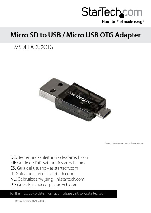
DE: Bedienungsanleitung - FR: Guide de l'utilisateur - ES: Guía del usuario - IT: Guida per l'uso - NL: Gebruiksaanwijzing - PT: Guia do usuário - MSDREADU2OTGMicro SD to USB / Micro USB OTG Adapter*actual product may vary from photosFCC Compliance StatementT his equipment has been tested and found to comply with the limits for a Class B digital device, pursuant to part 15 of the FCC Rules. These limits are designed to provide reasonable protection against harmful interference in a residential installation. This equipment generates, uses and can radiate radio frequency energy and, if not installed and used in accordance with the instructions, may cause harmful interference to radio communications. However, there is no guarantee that interference will not occur in a particular installation. If this equipment does cause harmful interference to radio or television reception, which can be determined by turning the equipment off and on, the user is encouraged to try to correct the interference by one or more of the following measures:• Reorient or relocate the receiving antenna.• Increase the separation between the equipment and receiver.• Connect the equipment into an outlet on a circuit different from that to which the receiver is connected.• Consult the dealer or an experienced radio/TV technician for help.Use of Trademarks, Registered Trademarks, and other Protected Names and Symbols his manual may make reference to trademarks, registered trademarks, and other protected names and/or symbols of third-party companies not related in any way to . Where they occur these references are for illustrative purposes only and do not represent an endorsement of a product or service by , or an endorsement of the product(s) to which this manual applies by the third-party company in question. Regardless of any direct acknowledgement elsewhere in the body of this document, hereby acknowledges that all trademarks, registered trademarks, service marks, and other protected names and/or symbols contained in this manual and related documents are the property of their respective holders.Table of ContentsProduct Diagram (1)Front View (1)Rear View (1)Introduction (2)Packaging Contents (2)System Requirements (2)Hardware Installation (3)Micro SD card Removal (4)Technical Support (5)Warranty Information (5)Product Diagram Front View1. Mirco USB PortRear View1. Micro SD SlotIntroductionPackaging Contents• 1 x Micro SD to USB / Micro USB OTG Adapter (MSDREADU2OTG) System Requirements• Micro SD Card• Host device (OTG-enabled Smartphone or USB-enabled Computer System)Hardware InstallationWARNING! Micro SD cards and computer system components require careful handling. If you are not careful with your Micro SD card lost data may result. Always handle your computer equipment with caution. Be sure that you are properly grounded by wearing an anti-static strap when handling computer components or discharge yourself of any static electricity build-up by touching a large grounded metal surface (such as the computer case) for several seconds.1. Remove the port cover from the USB port.2. Gently slide your Micro SD card into the Micro SD slot on the MSDREADU2OTG until you feel resistance.3. Connect MSDREADU2OTG to your host device.a) If connecting to an OTG-enabled Smartphone, connect the Micro USB port on the MSDREADU2OTG to the OTG port (Micro USB slot) on your Smartphone. Note: Not all Smartphones support an OTG adapter. Please contact the manufacturer of your Smartphone for more details regarding support for OTG and file format (FAT/ FAT32/exFAT).b) If connecting to a USB-enabled computer system, connect the USB port on the MSDREADU2OTG to an available USB port on your computer system.4. (Optional) The port cover can be placed back on the USB port, to protect the USB port as well as the Micro SD card.Micro SD card Removal1. Grasp the lip of your Micro SD card from the top of the Micro SD slot on the MSDREADU2OTG, and gently pull the card outward until it is removed.Note: Micro SD cards with a smaller lip, may be more difficult to remove, and removal may require a small tool, such as a fine set of tweezers.Technical SupportStarT ’s lifetime technical support is an integral part of our commitment to provide industry-leading solutions. If you ever need help with your product, visit /support and access our comprehensive selection of online tools, documentation, and downloads.For the latest drivers/software, please visit /downloads Warranty InformationThis product is backed by a two year warranty.In addition, Star warrants its products against defects in materials and workmanship for the periods noted, following the initial date of purchase. During this period, the products may be returned for repair, or replacement with equivalent products at our discretion. The warranty covers parts and labor costs only. StarT does not warrant its products from defects or damages arising from misuse, abuse, alteration, or normal wear and tear.Limitation of LiabilityIn no event shall the liability of Ltd. and USA LLP (or their officers, directors, employees or agents) for any damages (whether direct or indirect, special, punitive, incidental, consequential, or otherwise), loss of profits, loss of business, or any pecuniary loss, arising out of or related to the use of the product exceed the actual price paid for the product. Some states do not allow the exclusion or limitation of incidental or consequential damages. If such laws apply, the limitations or exclusions contained in this statement may not apply to you.Hard-to-find made easy. At , that isn’t a slogan. It’s a promise. is your one-stop source for every connectivity part you need. From the latest technology to legacy products — and all the parts that bridge the old and new — we can help you find the parts that connect your solutions.We make it easy to locate the parts, and we quickly deliver them wherever they need to go. Just talk to one of our tech advisors or visit our website. You’ll be connected to the products you need in no time.Visit for complete information on all products and to access exclusive resources and time-saving tools. is an ISO 9001 Registered manufacturer of connectivity and technology parts. was founded in 1985 and has operations in the United States,。
智原科技协助客户取得USB3.0主端控制器认证
智原科技协助客户取得USB3.0主端控制器认证
佚名
【期刊名称】《《中国集成电路》》
【年(卷),期】2010(19)7
【摘要】智原科技于近日宣布其客户睿思科技(FrescoLogic)的USB3.0主端控制器已通过USB—IF的所有测试,取得xHCI控制器的认证。
此控制器是采用智原科技的物理层IP所开发,是中国台湾地区第一、世界第二通过认证的
USB3.0主端控制器。
因应USB3.0未来的庞大商机,此控制器的通过认证,也为智原在计算机外设与多媒体高速传输接口的布局上,立下一个具重大意义的里程碑。
【总页数】1页(P9-9)
【正文语种】中文
【中图分类】TP273
【相关文献】
1.智原科技与银灿科技合作推出USBFlashDisk控制器单芯片 [J],
2.祥硕科技自行研发之USB3.0 ASM1042主控端芯片正式获得微软认证 [J],
3.智原科技USB 3.0装置端控制器通过USB-IF协会验证 [J],
4.Tektronix SuperSpeecl测试解决方案协助NEC Electronics通过世界首度USB3.0认证 [J],
5.美商睿思科技于IIC-China展出全球最快的USB3.0主端控制器解决方案 [J],因版权原因,仅展示原文概要,查看原文内容请购买。
CP2102N-MINIEK 产品说明书
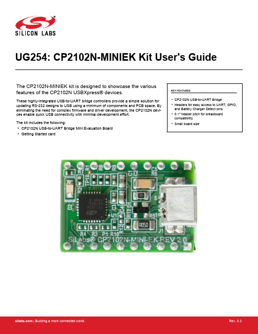
UG254: CP2102N-MINIEK Kit User's GuideThe CP2102N-MINIEK kit is designed to showcase the various features of the CP2102N USBXpress® devices.These highly-integrated USB-to-UART bridge controllers provide a simple solution for updating RS-232 designs to USB using a minimum of components and PCB space. By eliminating the need for complex firmware and driver development, the CP2102N devi-ces enable quick USB connectivity with minimal development effort.The kit includes the following:•CP2102N USB-to-UART Bridge Mini Evaluation Board •Getting Started cardKEY FEATURES•CP2102N USB-to-UART Bridge•Headers for easy access to UART, GPIO,and Battery Charger Detect pins •0.1" header pitch for breadboard compatibility •Small board size1. Getting Started1.Download and Install the Latest Virtual COM Port (VCP) Drivers.The Virtual COM Port (VCP) drivers enable the CP2102N to appear as a standard COM port. Download the latest version of driv-ers from the Silicon Labs website:https:///developers/usb-to-uart-bridge-vcp-driversIn most cases, select the default option without serial enumeration.2.Set Up Your Kit.a.Provide power to the board by connecting the mini USB connector to the PC using a mini USB cable (not provided). When aconnection has been established successfully, the LED (marked in the picture) lights up.LED3.Detect Your Device.The CP2102N device will appear as a COM port in Device Manager in Windows. As a virtual COM port, the CP210x functions identically to a real COM port from the reference point of both the host application and the serial device, and it can support serial device control requests defined in the Microsoft Win32® Communications API.4.Set up a Loop-Back Test.Short the CP210x RXD and TXD pins on header J2.5.Send and Receive Some Data.a.In Windows, open a serial terminal program (downloaded separately, RealTerm pictured) to verify the CP2102N UART func-tionality.b.Set the baud rate and select the COM port from Device Manager.c.Type in the transmit area. The characters should echo back after looping through the CP2102N TXD and RXD pins.6.Utilize the Available Resources.The next section includes additional resources available for the device, including documentation and application notes.Relevant Documentation 2. Relevant DocumentationThe following Application Notes are applicable to CP2102N devices:•AN721: USBXpress™ Device Configuration and Programming Guide — This application note guides developers through the config-uration process of USBXpress devices using Simplicity Studio [Xpress Configurator].•AN220: USB Driver Customization — This document and accompanying software enable the customization of the CP210x Virtual COM Port (VCP) and USBXpress drivers.•AN197: Serial Communications Guide for CP210x— This document describes recommendations for communicating with USBX-press CP210x devices using the Virtual COM Port (VCP) driver.•AN976: CP2101/2/3/4/9 to CP2102N Porting Guide — This document guides developers on how to migrate existing systems using the CP2101/2/3/4/9 to the CP2102N.•AN169: USBXpress® Programmer's Guide — This application note provides recommendations and examples for developing using the USBXpress direct-access driver.•AN807: Recertifying a Customized Windows Driver Package — This document describes the WHQL certification process required for customized drivers.•AN223: Runtime GPIO Control for CP210x — This document describes how to toggle GPIO pins from the USB host.Application Notes can be accessed on the Silicon Labs website (/interface-appnotes) or in Simplicity Studio using the [Getting Started]>[Application Notes] area of the launcher.Device Customization 3. Device CustomizationDevice customization for the CP2102N is done through Xpress Configurator, which is available in Simplicity Studio:/simplicityThe Simplicity Studio software package contains all the tools, drivers, configuration software, and documentation needed to use the CP2102N USB-to-UART Bridge Mini Evaluation Board.After downloading the latest version of Simplicity Studio and installing the software:1.Install the CP210x Virtual COM Port Driver during the software setup steps, if it's not already installed. This action can always beaccessed through [Help]>[Setup Tasks].2.Connect the CP2102N to the PC.3.Select [CP2102N] under [Devices]. On the board, a successful USB connection is established when the SUSPENDB LED (D2)turns on.4.Click on [Compatible Tools]>[Xpress Configurator] to open Xpress Configurator and customize the device.Documentation for each of the customization options is provided within Xpress Configurator. More information on each of these options can be found in AN721: USBXpress™ Device Configuration and Programming Guide, which is available on the Silicon Labs website (/interface-appnotes) or within Simplicity Studio under [Getting Started]>[Application Notes].4. Driver Options and Software Interface4.1 Virtual COM Port (VCP) DriverCP2102N devices are pre-programmed with a VID of 0x10C4 and PID of 0xEA60. This VID and PID combination matches the Virtual COM Port (VCP) driver. With this driver, the CP2102N will appear as a COM port and can be accessed using any terminal program or custom-written software. Install the VCP driver as part of the Simplicity Studio installation or download it directly from the Silicon Labs website (/interface-software).If the Virtual COM Port (VCP) drivers are used, the CP2102N will appear as a COM port in the Device Manager, as shown in the figure below. The CP2102N will always use the lowest available COM port for operation. For instance, if COM ports 1 and 2 are in use by other peripherals and applications, the CP2102N will use COM 3.The CP2102N functions identically to a COM port from the reference point of both the host application and the serial device, and it can support serial device control requests defined in the Microsoft Win32® Communications API. Examples for how to communicate with the device as a serial COM port are included in AN197: Serial Communications Guide for CP210x or in the SDK.Figure 4.1. CP2102N in Device Manager — VCP4.2 USBXpress DriverAn alternative driver is the USBXpress® direct-access driver, which is also available on the Silicon Labs website (/inter-face-software). Rather than appearing as a COM port, software can use a simple, high-level Application Program Interface (API) to pro-vide access to CP2102N for complete USB connectivity. No USB protocol or host device driver expertise is required. The USBXpress Development Kit includes Windows device drivers, Windows device driver installer, and host interface function library (host API) provi-ded in the form of a Windows Dynamic Link Library (DLL). See Application Note AN169: USBXpress® Programmer's Guide for detailed information on using the USBXpress drivers.If the USBXpress drivers are used, the CP2102N will appear as a USB USBXpress device as shown in the figure below. Examples for how to communicate with the device using the USBXpress interface are included in AN169: USBXpress® Programmer's Guide.Figure 4.2. CP2102N in Device Manager — USBXpress5. Hardware OverviewThe CP2102N Mini Evaluation Kit includes an evaluation board with a CP2102N device pre-installed for evaluation and preliminary soft-ware development. Numerous input/output (I/O) connections are provided to facilitate prototyping using the evaluation board. Refer to the figure below for the locations of the various I/O connectors.Table 5.1. CP2102N Mini Evaluation Board Component OverviewFigure 5.1. CP2102N Mini Evaluation Board5.1 USB Interface (J1)A Universal Serial Bus (USB) mini connector (J1) is provided to facilitate connections to the USB interface on the CP2102N. See the table below for the USB pin definitions.Table 5.2. USB Mini Connector Pin DescriptionsHardware Overview 5.2 Headers (J2 and J5)The J2 and J5 headers provides direct access to the CP2102N power, reset, UART, suspend, and charge enable pins. See the table below for the J2 and J5 pin descriptions.Table 5.3. J2 Pin DescriptionsTable 5.4. J5 Pin Descriptions | Building a more connected world.Rev. 0.3 | 11Schematics and BOM 6. Schematics and BOM6.1 Board FilesThe schematics and bill of materials (BOM) for the CP2102N USB-to-UART Bridge Mini Evaluation Board are available through Sim-plicity Studio when the kit documentation package has been installed. To access these documents, click the [Documentation] tab in the launcher, and manually specify the connected board.6.2 Board Revision HistoryRev00 Boards•Initial production revision.•BOM specifies CP2102N-A01 chip revision.Rev00 errata:•Board does not include required voltage divider on VBUS pin as described in section 2.3 of the CP2102N Datasheet.Rev 2.0 Boards•Second production revision.•BOM specifies CP2102N-A02 chip revision.•Added voltage divider to VBUS pin.•Added optional pulldown resistor for line break support (CP2102N-A02 only).Rev 2.0 errata:•These boards do not currently have any known issues.Revision History 7. Revision HistoryRevision 0.1October, 2016•Initial revision.Revision 0.2December, 2019•Updated Revision History format.•Updated images throughout to reflect hardware revision 2.0.•Updated 6.2 Board Revision History to reflect hardware revision 2.0.•Corrected error in pinout diagram in Figure 5.1 CP2102N Mini Evaluation Board on page 9.Revision 0.3May, 2021•Updated the link of the VCP Driver in 1. Getting Started.•Updated the title of AN721, AN976, AN169, AN807.•Corrected Pin 1 and Pin 2 descriptions in Table 5.4 J5 Pin Descriptions on page 11.Silicon Laboratories Inc.400 West Cesar Chavez Austin, TX 78701USAIoT Portfolio/IoTSW/HW/simplicityQuality /qualitySupport & Community/communityDisclaimerSilicon Labs intends to provide customers with the latest, accurate, and in-depth documentation of all peripherals and modules available for system and software imple-menters using or intending to use the Silicon Labs products. Characterization data, available modules and peripherals, memory sizes and memory addresses refer to each specific device, and “Typical” parameters provided can and do vary in different applications. Application examples described herein are for illustrative purposes only. Silicon Labs reserves the right to make changes without further notice to the product information, specifications, and descriptions herein, and does not give warranties as to the accuracy or completeness of the included information. Without prior notification, Silicon Labs may update product firmware during the manufacturing process for security or reliability reasons. Such changes will not alter the specifications or the performance of the product. Silicon Labs shall have no liability for the consequences of use of the infor -mation supplied in this document. This document does not imply or expressly grant any license to design or fabricate any integrated circuits. The products are not designed or authorized to be used within any FDA Class III devices, applications for which FDA premarket approval is required or Life Support Systems without the specific written consent of Silicon Labs. A “Life Support System” is any product or system intended to support or sustain life and/or health, which, if it fails, can be reasonably expected to result in significant personal injury or death. Silicon Labs products are not designed or authorized for military applications. Silicon Labs products shall under no circumstances be used in weapons of mass destruction including (but not limited to) nuclear, biological or chemical weapons, or missiles capable of delivering such weapons. Silicon Labs disclaims all express and implied warranties and shall not be responsible or liable for any injuries or damages related to use of a Silicon Labs product in such unauthorized applications. Note: This content may contain offensive terminology that is now obsolete. Silicon Labs is replacing these terms with inclusive language wherever possible. For more information, visit /about-us/inclusive-lexicon-projectTrademark InformationSilicon Laboratories Inc.®, Silicon Laboratories ®, Silicon Labs ®, SiLabs ® and the Silicon Labs logo ®, Bluegiga ®, Bluegiga Logo ®, Clockbuilder ®, CMEMS ®, DSPLL ®, EFM ®, EFM32®, EFR, Ember ®, Energy Micro, Energy Micro logo and combinations thereof, “the world’s most energy friendly microcontrollers”, Ember ®, EZLink ®, EZRadio ®, EZRadioPRO ®, Gecko ®, Gecko OS, Gecko OS Studio, ISOmodem ®, Precision32®, ProSLIC ®, Simplicity Studio ®, SiPHY ®, Telegesis, the Telegesis Logo ®, USBXpress ® , Zentri, the Zentri logo and Zentri DMS, Z-Wave ®, and others are trademarks or registered trademarks of Silicon Labs. ARM, CORTEX, Cortex-M3 and THUMB are trademarks or registered trademarks of ARM Hold-ings. Keil is a registered trademark of ARM Limited. Wi-Fi is a registered trademark of the Wi-Fi Alliance. All other products or brand names mentioned herein are trademarks of their respective holders.。
USB-ASP-ISP使用手册
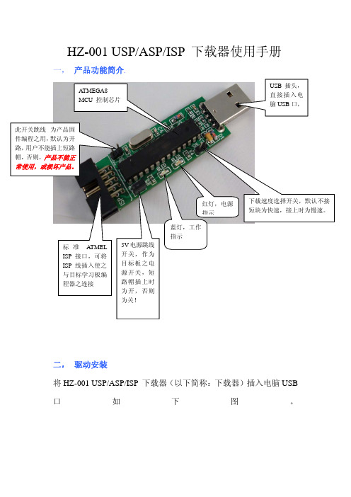
HZ-001 USP/ASP/ISP下载器使用手册一, 产品功能简介.二, 驱动安装将HZ-001 USP/ASP/ISP 下载器(以下简称:下载器)插入电脑USB 口如下图。
标准ATMEL ISP 接口,可将ISP 线插入使之与目标学习板编程器之连接下载速度选择开关,默认不接短块为快速,接上时为慢速。
为产品固默认为开用户不能插上短路产品不能正常使用,或损坏产品。
ATMEGA8MCU 控制芯片红灯,电源指示5V 电源跳线开关,作为目标板之电源开关,短路帽插上时为开,否则为关!蓝灯,工作指示此时红灯会亮!电脑会显示找到新硬件:接着将赠送的驱动CD-ROM光盘插入电脑光驱,选自动安装或从列表或指定位置安装(高级)点下一步:完成安装后在《我的电脑》设备管理器上显示:此表示显示安装下载器成功三, 下载器软件使用!1,简单使用如下:此ISP软件不用安装,将光盘(ISP编程下载软件)COPY到桌面(或指定的文件夹下)直接点击PROGISP. EXE 即可打开软件,以下载AT89S51单片机程序为例,按如下图指示选择选项,将ISP线连接到目标板,再后点“自动”就可以将要下载的HEX文件烧录到单片机中!二,详细使用请参考以下配置: E progisp的主界面(基本配置)progisp的主界面(熔丝导航)程序启动后默认为非脱机数据模式,如果“脱机数据“选择后,“自动”等按钮将会变为”写入映像”如下图的按钮,用来对脱机编程下载器的脱机数据的读写操作。
脱机数据的编程内容及选项与正常操作时选项相同。
(关于脱机编程的详细情况见脱机下载器的说明书)1,正常编程的步骤。
连接好目标板,加电,先调入编程数据,选择熔丝位,选择自动完成的设置。
按下“自动“完成编程。
(“脱机数据“一定不能选择)2,下载脱机数据。
插入脱机下载器,调入需要脱机编程的数据,选择熔丝位,选择“脱机数据“,选择脱机操作的自动完成的设置的参数。
按下“写入映像”完成数据下载(“下载脱机数据“一定要选择)特别提示:“提供时钟“选择后配合本工作室的下载器,可以为目标板的cpu提供时钟,这样可以解锁被锁定的芯片三、工程管理。
USB-CDROM启动盘制作方法
USB-CDROM启动盘制作方法网上有很多U盘启动盘制作工具和相关的制作方法。
自己在制作过程中,总结出我个人认为最实用的一种制作方法,它不仅可以随时更新,还免去了重复量产的麻烦,再也不用因为光驱损坏或到处借系统光盘而烦恼了。
此种方法是将U盘量产成一个USB-CDROM启动盘。
附属盘还当U盘使用。
有风险,需谨慎,初学的时候,我弄坏了两个U盘。
一、准备工具1、一个可支持量产的U盘,容量最好在2G以上。
2、ISO打开软件:UltraISO 9.0以上版本。
3、将U盘进行量产成USB-CDROM的软件:(1)、U盘芯片型号检测工具ChipGenius(2)、量产工具:不同U盘的量产工具不同。
4、根据需要进行准备的镜像文件:我制作的是一个包含win7和xp两种系统安装的启动盘,所以分别下载了两个镜像文件。
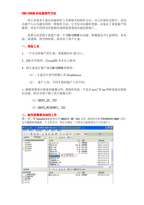
(1)GHOST_XP_ ISO(2)GHOST_WINDOWS7_ ISO二、制作前需要完成的工作第一步、用UltraISO 9.0软件打开GHOST_XP_ ISO文件,找到其中的WINXPSP3.GHO文件,点右键提取到随便一个文件夹中,然后点确定(只要自己能找到这个文件就行)。
第二步、提取文件完成后,不要关闭UltraISO 9.0软件,接着把WINXPSP3.GHO删除,文件总大小变成了58MB。
第三步、点菜单栏-文件-把这个文件另存到刚才提取GHO的文件夹里待用。
WIN7系统镜像文件提取方法只要重复第一步就可以了。
第四步、插入U盘,打开U盘芯片型号检测工具,这里就拿我的U盘做示范了。
经检测,芯片制造商:SMI(慧荣) 芯片型号: SM321~SM325 。
现在到网上查找下载对应的芯片型号量产工具和使用教程。
(制作前一定要弄懂它的使用方法)。
三、开始制作第一步、打开已下载的量产工具软件。
第二步、进入量产工具,按步骤进行。
图一图二图三图四图五第三步、提示量产成功后,点击Quit退出,关闭所有的软件,并拔插U盘。
U盘量产详解
U盘量产详解第一篇有关量产工具1. 什么是量产工具,有何作用量是指批量的意思,即量产工具可以一次性生产出很多U盘,只要你的USB孔足够。
量产工具是针对U盘主控芯片进行操作的由厂商开发的低层软件,作用:1)低格U盘2)生产加密盘3)分区,可以生产只读分区,更改U盘介质类型(removabel 和fixed)4)量产出USB-CDROM,此作用可以做启动光盘。
2. 读卡器所组成的U盘能量产出CDROM吗?不能,也许以后会有这样的读卡器。
3.移动硬盘能量产吗?目前不能,芯邦在搞,据说明年会出来。
如果真出来这样的工具,CDDVD销量可能要大大下降了。
4.所有U盘都能量产吗?应该是的,就看有没有合适的量产工具放出。
主控厂商肯定都有的。
5.如何判断U盘主控1) 最准确方法-拆盘2) 根据软件vid & pid结合已知的USB厂家列表来判断主控。
但vid & pid是可以随意改的,对于劣质flash存储U盘可能不准;另外也可以用VMWARE来判断。
参见相关贴子。
6. 什么量产工具好都差不多,就看熟不熟练。
7. 使用量产工具要注意什么1)不要怕,大胆的弄,U盘不会坏的,如果有报废的,请低价卖给我,我收。
2)量产也有经常出错的时候,如U盘变成8M,同1),再次进行。
8. 量产出的CD-ROM最大可以是多少不同版本,牌子不一样,我的4G的ICREATE的可以量产出1G多点。
这个技术指标开发商不透露。
9. 量产工具版本越高越好吗?不一定,还要看是不是支持你的U盘的类型。
10. 量产出的CDROM启动兼容性、速度怎样?新主板几乎都可以,老主板有的HDD或ZIP都不行,但CDROM可以;如果主板支持USB2.0且打开“high speed”,U 盘也支持USB2.0这个启动速度是很快的,用来安装XP就是一例。
11. 不同的量产工具为什么不能通用主要区别在于不同厂家的主控芯片都有其保密的指令与函数,没法通用。
USB-4750 32通道隔离数字I O USB模块用户手册
USB-475032-Channel Isolated Digital I/O USB Module User ManualCopyrightThe documentation and the software included with this product are copy-righted 2009 by Advantech Co., Ltd. All rights are reserved. Advantech Co., Ltd. reserves the right to make improvements in the productsdescribed in this manual at any time without notice. No part of this man-ual may be reproduced, copied, translated or transmitted in any form or by any means without the prior written permission of Advantech Co., Ltd.Information provided in this manual is intended to be accurate and reli-able. However, Advantech Co., Ltd. assumes no responsibility for its use, nor for any infringements of the rights of third parties, which may result from its use.AcknowledgementsIntel and Pentium are trademarks of Intel Corporation.Microsoft Windows and MS-DOS are registered trademarks ofMicrosoft Corp.All other product names or trademarks are properties of their respective owners.Part No. 2003M7500047501st EditionPrinted in Taiwan July 2009USB-4750 User Manual iiProduct Warranty (2 years)Advantech warrants to you, the original purchaser, that each of its prod-ucts will be free from defects in materials and workmanship for two years from the date of purchase.This warranty does not apply to any products which have been repaired or altered by persons other than repair personnel authorized by Advantech, or which have been subject to misuse, abuse, accident or improper instal-lation. Advantech assumes no liability under the terms of this warranty as a consequence of such events.Because of Advantech’s high quality-control standards and rigorous test-ing, most of our customers never need to use our repair service. If an Advantech product is defective, it will be repaired or replaced at no charge during the warranty period. For out-of-warranty repairs, you will be billed according to the cost of replacement materials, service time and freight. Please consult your dealer for more details.If you think you have a defective product, follow these steps:1.Collect all the information about the problem encountered. (Forexample, CPU speed, Advantech products used, other hardwareand software used, etc.) Note anything abnormal and list anyonscreen messages you get when the problem occurs.2.Call your dealer and describe the problem. Please have your man-ual, product, and any helpful information readily available.3.If your product is diagnosed as defective, obtain an RMA (returnmerchandize authorization) number from your dealer. This allows us to process your return more quickly.4.Carefully pack the defective product, a fully-completed Repair andReplacement Order Card and a photocopy proof of purchase date(such as your sales receipt) in a shippable container. A productreturned without proof of the purchase date is not eligible for war-ranty service.5.Write the RMA number visibly on the outside of the package andship it prepaid to your dealer.iiiCEThis product has passed the CE test for environmental specificationswhen shielded cables are used for external wiring. We recommend the use of shielded cables. This kind of cable is available from Advantech. Please contact your local supplier for ordering information.Technical Support and AssistanceStep 1. Visit the Advantech web site at /support where you can find the latest information about the product.Step 2. Contact your distributor, sales representative, or Advantech's cus-tomer service center for technical support if you need additionalassistance. Please have the following information ready beforeyou call:- Product name and serial number- Description of your peripheral attachments- Description of your software (operating system, version, appli-cation software, etc.)- A complete description of the problem- The exact wording of any error messagesDocument FeedbackTo assist us in making improvements to this manual, we would welcome comments and constructive criticism. Please send all such - in writing to: *********************Safety Precaution - Static ElectricityFollow these simple precautions to protect yourself from harm and the products from damage.1.To avoid electrical shock, always disconnect the power from yourPC chassis before you work on it. Don't touch any components onthe CPU card or other cards while the PC is on.2.Disconnect power before making any configuration changes. Thesudden rush of power as you connect a jumper or install a card maydamage sensitive electronic components.USB-4750 User Manual ivContentsChapter1Introduction (2)1.1Hardware Features (2)1.2Software Overview (3)1.2.1More on the CD (3)Chapter2Installation (6)2.1Unpacking (6)2.2Driver Installation (7)2.3Hardware Installation (9)2.4Hardware Uninstallation (9)Figure 2.1:Unplug or Eject Hardware Dialog (10)Figure 2.2:Stop a Hardware device dialog box (10)Chapter3Signal Connections (12)3.1Overview (12)3.2I/O Connectors (12)3.2.1Pin Assignments (12)Figure 3.1:I/O Connector Pin Assignment (12)3.2.2I/O Connector Signal Description (13)Table 3.1:I/O Connector Signal Descriptions (13)3.2.3LED Indicator Status Description (13)Table 3.2:LED Indicator Status Description (13)3.3Isolated Digital I/O Connections (14)3.3.1Dry/Wet Contact Support for Digital Input (14)Figure 3.2:Isolated Digital Input Connections (14)3.3.2Isolated Digital Output Connections (15)Figure 3.3:Isolated Digital Output Connections (15)3.4Field Wiring Considerations (16)Appendix A Specifications (18)A.1Isolated Digital Input (18)A.2Isolated Digital Output (18)A.3Optically-Isolated Counter (18)A.4General (18)v Table of ContentsUSB-4750 User Manual viC H A P T E R1Introduction Sections include:• Hardware Features • Software OverviewChapter 1 IntroductionThank you for buying the Advantech’s USB-4750 data acquisition mod-ule. The Advantech USB-4750 is a powerful data acquisition (DAS)module for the USB port. It features a unique circuit design and complete functions for data acquisition and control.1.1 Hardware FeaturesUSB-4750 features excellent measurement & control functions:• 32 isolated digital input/output channels• High-voltage isolation up to 2,500 VDC on all channels• Dry/wet contact support• Interrupt handling capability• High-sink current for isolated output channels (100mA max./Channel)• Digital output value retained after hot system reset• Programmable Power-Up States for output channels• Wiring ternimals on moduleNote:You can install up to sixteen USB-4750’s to asystem because of the restriction of deviceBoardIDNote:The power output of an USB port is 500 mA,while the USB-4750 requires 350 mA (Max.).This means that if an USB hub is used, it willneed an external power supply to support morethan one USB-4750 device.Note:For detailed specifications of USB-4750, pleaserefer to Appendix A, Specifications.USB-4750 User Manual21.2 Software OverviewAdvantech offers a rich set of DLL drivers, third-party driver support and application software on the companion CD-ROM to help fully exploit the functions of your device. Advantech’s Device Drivers feature a complete I/O function library to help boost your application performance and work seamlessly with development tools such as Visual C++, Visual Basic,Inprise C++ Builder, and Inprise Delphi.1.2.1 More on the CDFor instructions on how to begin programming in each development tool, Advantech offers some tutorial chapters in the Device Drivers Manual for your reference. Please refer to the corresponding sections in these chap-ters on the Device Drivers Manual to begin your programming efforts.You can also look at the example source code provided for each program-ming tool, since they can get you very well oriented.The Device Drivers Manual can be found on the companion CD-ROM.Alternatively, if you have already installed the Device Drivers on your system, The Device Drivers Manual can be readily accessed through the Start button:Start/Programs/Advantech Automation/Advantech Device Manager / Device Driver’s ManualThe example source code can be found under the corresponding installa-tion folder such as the default installation path:\Program Files\Advantech\ADSAPI\Examples3Chapter 1USB-4750 User Manual4C H A P T E R2Installation Sections include:• Unpacking • Driver Installation • Hardware Installation • Hardware UninstallationChapter 2 Installation2.1 UnpackingAfter receiving your USB-4750 package, please inspect its contents first.The package should contain the following items:• USB-4750 Module• Shielded USB 2.0 Cable (1.8 m)• Companion CD-ROM (DLL driver included)• User ManualThe USB-4750 Module harbors certain electronic components vulnerable to electrostatic discharge (ESD). ESD could easily damage the integrated circuits and certain components if preventive measures are not carefully paid attention to. Before removing the module from the antistatic plastic bag, you should take following precautions to ward off possible ESD damage:• Touch the metal part of your computer chassis with your hand to dis-charge static electricity accumulated on your body. One can also use a grounding strap.• Make contact between the antistatic bag and ground before opening.After taking out the module, you should first:Inspect the module for any possible signs of external damage (loose or damaged components, etc.). If the module is visibly damaged, pleasenotify our service department or our local sales representative immedi-ately. Avoid using a damaged module with your system.• Avoid physical contact with materials that could hold static electricitysuch as plastic, vinyl and Styrofoam.USB-4750 User Manual62.2 Driver InstallationWe recommend you install the software driver before you install theUSB-4750 module into your system, since this will guarantee a smooth installation process.The 32-bit DLL driver Setup program for the USB-4750 module isincluded on the companion CD-ROM that is shipped with your module package. Please follow the steps on the following page to install thedriver software:7Chapter 2USB-4750 User Manual 8For further information on driver-related issues, an online version of the Device Drivers Manual is available by accessing the following path:Start\Programs\Advantech Automation\Device Manager\Device Driver’s Manual2.3 Hardware InstallationNote:Make sure you have installed the software driverbefore you install the module (please refer to Sec-tion 2.2 Driver Installation)After the DLL driver installation is completed, you can now go on toinstall the USB-4750 module in any USB port that supports the USB 1.1/2.0 standard, on your computer. It is suggested that you refer to the computer’s user manual if you have any doubts. Please follow thesteps below to install the module on your system.Step 1: Touch the metal part on the surface of your computer to neutral-ize the static electricity that might be in your body.Step 2: Plug your USB module into the selected USB port. Use of exces-sive force must be avoided; otherwise the module might get damaged.Note:In case you installed the module without installing the DLL driver first, Windows 2000/XP will recognize yourmodule as an “unknown device” after reboot, and willprompt you to provide necessary driver. You shouldignore the prompting messages (just click the Cancelbutton) and set up the driver according to the stepsdescribed in Section 2.2 Driver Installation.After your module is installed, you can configure it using the Advantech Device Manager. The Device Driver's Manual can be found at:Start\Programs\Advantech Automation\Advantech Device Man-ager\Device Driver’s Manual2.4 Hardware UninstallationThough the Advantech USB modules are hot swappable, we still recom-mend you to follow the hardware un-installation procedure to avoid any unpredictable damages to your device or your system.Step1: Close the applications of the USB module.9Chapter 2Step2: Right click the “Unplug or Eject Hardware” icon on your task bar.Figure 2.1: Unplug or Eject Hardware DialogStep3: Select “Advantech USB-4750 Device” and press “Stop” Button.Figure 2.2: Stop a Hardware device dialog box Step4: Unplug your USB device from the USB port.Note:Please make sure that you have closed the application before unplugging the USB device, otherwise unexpectedsystem error or damage may occur.USB-4750 User Manual10C H A P T E R3Signal Connections Sections include:• Overview • Isolated Digital I/O Connections • Field Wiring ConsiderationsUSB-4750 User Manual 12Chapter 3 Signal Connections3.1 Overview Maintaining good signal connections is one of the most important factors in ensuring that your application system is sending and receiving data correctly. A good signal connection can avoid unnecessary and costly damage to your PC and other hardware devices.3.2 I/O ConnectorsUSB-4750 is equipped with plug-in screw-terminal connectors that facili-tate connection to the module without terminal boards or cables.3.2.1 Pin Assignments Figure 3.1: I/O Connector Pin AssignmentNote:IDI0 shares the same pin with INT0IDI4 shares the same pin with INT0_GIDI7 shares the same pin with CNT0IDI8 shares the same pin with INT1IDI12 shares the same pin with INT1_GIDI15 shares the same pin with CNT113Chapter 33.2.2 I/O Connector Signal Description3.2.3 LED Indicator Status DescriptionThe USB Module is equipped with a LED indicator to show the current status of the device. When you plug the USB device into the USB port, the LED indicator will blink five times and then stay lit to indicate that it is on. Please refer to the following table for detailed LED indicator status information.SignalReference Direction Description IDI<0~15>GND Input Isolated digital input channels INT<0,1>INT_G Input Interrupt trigger sources.INT<0,1>_G--Ground for interrupt T<0,1>GND Input Isolated input counters IDO<0~15>GND Output Isolated digital output channels COM<0,1>--Common pins for connecting induc-tive loads of isolated output channels GND --GroundLED StatusDescription ONDevice ready for work OffDevice not ready to work Slow Blinking (5 times)Device Initialization Fast Blinking(Depends on data transfer speed).Device working3.3 Isolated Digital I/O Connections3.3.1 Dry/Wet Contact Support for Digital InputEach digital input channel accepts either dry contact or 0 ~ 60 VDC wet contact inputs. Dry contact capability allows the channel to respond to changes in external circuitry (e.g., the closing of a switch in the external circuitry) when no voltage is present in the external circuit. Figure 3-1 shows external circuitry with both wet and dry contact components, con-nected as an input source to one of the card's digital input channels.Figure 3.2: Isolated Digital Input ConnectionsUSB-4750 User Manual143.3.2 Isolated Digital Output ConnectionsEach of 8 isolated digital output channels comes equipped with a Darling-ton transistor. Every 8 output channels share common collectors and inte-gral suppression diodes for inductive loads. Channels 0 ~ 7 use COM0, and channels 8 ~ 15 use COM1 as a common pin. If an external voltage (5 ~ 40 V) is applied to an isolated output channel (IDO 0 ~ IDO 15) while it is being used as an output channel, the current will flow from the external voltage source to the card. Please take care that the current through each GND pin not exceed 100 mA.Figure 3.3 shows how to connect an external output load to the card's iso-lated outputs.Figure 3.3: Isolated Digital Output Connections15Chapter 33.4 Field Wiring Considerations• When you use USB-4750 to acquire data from outside, noises in theenvironment might significantly affect the accuracy of your measure-ments if due cautions are not taken. The following measures will behelpful to reduce possible interference running signal wires betweensignal sources and the USB-4750.• The signal cables must be kept away from strong electromagneticsources such as power lines, large electric motors, circuit breakers orwelding machines, since they may cause strong electromagnetic inter-ference. Keep the analog signal cables away from any video monitor,since it can significantly affect a data acquisition system.• If the cable travels through an area with significant electromagneticinterference, you should adopt individually shielded, twisted-pair wires as the analog input cable. This type of cable has its signal wires twisted together and shielded with a metal mesh. The metal mesh should only be connected to one point at the signal source ground.• Avoid running the signal cables through any conduit that might havepower lines in it.• If you have to place your signal cable parallel to a power line that has a high voltage or high current running through it, try to keep a safe dis-tance between them. Or place the signal cable in a right angle to thepower line to minimize the undesirable effect.USB-4750 User Manual16A P P E N D I X A SpecificationsUSB-4750 User Manual 18Appendix A Specifications A.1 Isolated Digital Input A.2 Isolated Digital Output A.3 Optically-Isolated CounterA.4 General Channels16Interrupt InputsDI0, DI8Optical Isolation2500 VDC Opto-isolator ResponseTime25 µs Input Voltage Dry contact or0 ~ 5 V for logic 05 ~ 60 V for logic 1Channels16Optical Isolation2500 VDC Opto-isolatorResponse Time25µs Output Voltage5 ~ 40 VDC Sink Current 100mA/ch. Max. 1.1A/total Max.Channels 2 independentResolution32-bit counters (low 16bit by hardware and high 16bit by firmware)Base Clock Internal 20MHz max. 2 independent program-mable clock sources Frequency MeasurementInput frequency from 0.1Hz to 8Mhz External Input Divide 2 to 65535I/O Connector Type10-pin screw terminal *4Dimensions132 X 80 X 32 mm (5.2” X 3.2” X 1.3”)Power Consumption5 V @ 350 mA max.TemperatureOperation 0~60 (32~140) (refer to IEC 68-2-1, 2)Storage -20~70 (-4~158)Relative Humidity 5%~95% RH non-condensing (refer to IEC 68-2-1, 2)。
2019-u盘装系统找不到ISO-优秀word范文 (7页)
本文部分内容来自网络整理,本司不为其真实性负责,如有异议或侵权请及时联系,本司将立即删除!== 本文为word格式,下载后可方便编辑和修改! ==u盘装系统找不到ISO篇一:教你如何U盘装系统ISOIMG文件教你如何U盘装系统ISO/IMG文件一、准备工作首先准备U盘一个、二、启动盘制作工具——U大师U盘启动盘制作工具、装机版的WIN7ISO文件二、操作步骤1.利用U大师U盘启动盘制作工具(V1.1.0版)将U盘制作成启动U盘2.在制作好的启动U盘目录中另新建一个ISOs文件夹,将ISO文件存入此文件夹3.插入启动U盘,重启电脑,在U盘启动菜单中选择【11】,如图:4.根据上方列出的ISOs文件夹中所有的ISO镜像文件,输入要安装的系统对应的序号,例如,这里选择安装的是WIN7系统,则输入02,,回车即可,如图:5.按下ENTER键6.之后的界面就是加载的ISO镜像文件安装画面,这里不再叙述,详细可参看原版WIN7系统的安装教程。
篇二:U盘安装原版ISO镜像系统U盘启动WinPE下安装XPSP3原版ISO镜像文件的几种方法:一、WinPE下手动安装XPSP3原版ISO镜像文件的方法:1、网上下载原版ISO,放到U盘启动盘根目录,如U:\2、将这个U盘启动盘插入电脑USB接口,重启电脑进入PE系统。
3、在WinPE系统下格式化你要安装的盘(开始—>我的电脑—>右键C盘—>格式化)4、用WinPE系统中的虚拟光驱加载ISO (开始—>程序—>VIRTUAL..—>找到并装入ISO—>确定—>最小化)5、进装载ISO的虚拟光驱盘符-->双击Setup.exe,安装程序开始运行6、点击安装Micrcsoft Windows XP—>下一步7、①选中全新安装—>下一步②选中我接受这个协议—>下一步③输入产品密钥 MRX3F-47B9T-2487J-KWKMF-RPWBY—>下一步④语言和区域(默认) 语言(中国)⑤高级选项:勾选从安装CD复制所有安装文件,勾选我想在安装过程中选择安装驱器号和磁盘分区—>确定/下一步⑥选择否,跳过此步聚—>下一步⑦选择否,跳过这一步继续安装windows—>下一步⑧选择跳过这一步,继续安装windows—>下一步开始复制安装文件到硬盘:⑨正在复制安装文件(开始复制文件到复制文件结束,即绿色进度条走完)⑩正在重新启动计算机(即红色进度条走完,会跳出一个话框,千万别点话框中的“确定”按钮,不要理采它)8、拔出U盘(就是红色进度条走完了就拔掉U盘)9、手动重启电脑(这一步千万别漏了)10、①选中要现在安装windows XP,请按ENTER—>回车②选中要在所选项目上安装windows XP,请按ENTER—>回车③选中保持现有文件系统—>回车经过一段较长时间(其间有一段时间黑屏,这是正常的)之后:11、再次进入区域和语言选项①自定义(默认) ②语言信息(默认)—>下一步12、输入①姓名(随便填) ②单位(随便填)—>下一步输入①系统管理员密码(可不填) ②确认密码—>下一步13、日期和时间设置(默认)—>下一步14、网络设置选中典型设置—>下一步15、工作组或计算机①选中不,此计算机不在网络上或者在没有域的网络上②把此计算机成为下列工作组的一个成员(默认)—>下一步再经过一些时间:16、显示设置—>确认—>确认—>下一步17、选中自动更新—>下一步18、谁会使用这台计算机您的姓名(随便填一个)—>下一步—>完成—>进入桌面--------------------------------------------------------------------二、WinPE下自动安装XPSP3原版ISO镜像文件的方法:1、网上下载并解压winnt文件得到winnt.sif和winnt32—>保存到文件名为winnt的文件夹中。
USB_bootloader_UG_cn
USB bootloader固件使用说明V1.0 特点:速度快,484K的程序也只需1秒搞定。
目录一、烧录USB BOOTLOADER固件二、编译用户程序附录:本站的开发板出厂前已经预烧录了USB bootloader固件(基于LPC23XX)。
如果擦除了,需通过如下步骤烧录。
注★:USB BOOTLOADER相关信息:1.USB BOOTLOADER固件占用16K字节即0x0000~0x3FFF为USBBOOTLOADER占用. 用户程序需从:0x4000的地址存放(本说明中有教怎么样把程序定位编译并生成BIN文件)2.板子一上电程序是先运行USB BOOTLOADER,程序会判断有KEY4(LPC2378 KIT)是否为低电平,如为低电平则运行USB BOOTLOADER程序,如为高电平则直接跳到0X4000处执行用户程序。
3.USB BOOTLOADER运行后,插到PC会虚拟成一个移动U盘,盘符为:CRP-MCU123 4.更新固件时只需把U盘中的FIRMWARE.BIN文件删除,COPY进去你的用户程序即可。
然后复位芯片即可运行。
5.固件最大可以为484KB。
因为LPC2378最大为500K,其中固件占用16K所以最大的程序只能484K。
一、烧录USB BOOTLOADER固件这里只介绍通过ISP方式烧录(也可以用JLINK或ULINK2,JTAG的方式来烧录)安装好FLASH MAGIC双击运行一直点NEXT直到安装完成.注★:完成下面的步骤前,先把开发板上电及连接板子的COM0到PC的串口上。
运行FLASH MAGIC1.设置串口,波特率,选择芯片型号。
2.选择擦除所FLASH及保密位。
3.选择烧录的文件:4.加选项目可以不选5.设置自动下载:T1>T2,时间可以适当加长. 6.烧录开始直接完成:然后插上把板子上的USB与PC的USB相连。
(设置好板子上的J1,J2,J5跳线)PC会发现一个U盘设备,并自动完成安装驱动。
TrustTimeout后无线USB PTK的管理方法
TrustTimeout后无线USB PTK的管理方法
Sachin ATHALYE;杨骁勇
【期刊名称】《世界电子元器件》
【年(卷),期】2008(000)002
【摘要】根据无线USB规范1.0,在TrustTimeout(可信超时)后,旧的成对临时密钥(Pairwise Temporal Key,PTK)过期,需要更换。
但该规范并没有明确定义何时应抛弃旧的PTK。
在TrustTimeout后,无线USB主机可以立即删除PTK,或永久保留,也可以保留某段时间。
本文根据这一特点提出了一种新的PTK 管理方法。
它有两个新颖之处:
【总页数】3页(P15-17)
【作者】Sachin ATHALYE;杨骁勇
【作者单位】恩智浦半导体;恩智浦半导体
【正文语种】中文
【中图分类】TN92
【相关文献】
1.恩智浦无线USB芯片获得USB-IF认证 [J],
2.利用USB延长线改善USB无线网卡的传输能力 [J], 白仰东
3.无线USB(WUSB)的研究 [J], 孙亮;
4.Alereon通过USB-IF的无线USB认证 [J],
5.第一款符合无线USB1.0规范的原生从端芯片通过USB—IF的无线USB认证[J],
因版权原因,仅展示原文概要,查看原文内容请购买。
U盘起动的制做
U盘起动的制做现在的u盘是越来越大,装一个系统是轻而易举的事情,我们可以把u盘作为系统盘使用,具体看下面方法:准备工作:1. U盘,4G以上为佳2. 电脑一台,这里不用说了3. 系统镜像(.iso文件):一个PE系统镜像,推荐“老毛桃PE之撒手不管版”。
这个版本大概100+MB的样子,我自己在这个镜像的基础上做了一些小修改,使之缩小到了79MB。
一个Windows 7 Ultimate RTM镜像,这个最好是原版的,目前我尚不推荐有修改过的Windows 7。
Ubuntu 10.04镜像文件。
这个从Ubuntu的官方上下载。
(点此下载)4. Windows 7 USB DVD Download Tool。
这个微软官方也有下载,此软件很小。
点此下载5. 数码之家出品U盘主控芯片检测工具。
点此下载6. 对应的量产工具。
这个在下面会有介绍。
二、步骤用上面的提到的主控芯片检测工具检测出U盘的主控芯片并下载量产工具。
这个主控芯片不同的U盘差异很大,有时同一型号的U盘,只因为生产的批次不同,芯片也是不同的。
我的Kingston DataTraveler 4GB的主控芯片是SK6211的,我下载到的量产工具名字就叫SK6211_20090227_BA。
量产U盘量产原本是工厂里的一道操作工序,但是现在由于一些软件泄露等等,普通用户也可以量产了。
我们量产的目的是把U盘分割为一个光盘加一个U盘。
什么意思呢?我们的普通U盘插到电脑上就显示为一个U盘的图标,但是量产出多重扇区的U盘就不一样的,插到电脑上之后显示为两个图标(两个驱动器),一个是光盘,一个是普通的U盘。
那个光盘驱动器就和真正的光盘一样,只能读文件,不能写文件、删文件,并且一般的格式化是奈何不了它的,就连大部分的专业分区工具(比如PM)都识别不了它的文件系统(在Windows里显示为CDFS),最棒的是,这是底层的,这意味着它在BIOS里也是可以识别的,如果光盘是可引导的,那么就可以用它来启动系统。
量产成功的U盘在845GV主板上启动不了怎么办?
量产成功的U盘在845GV主板上启动不了怎么办?
导读:如今电脑早已进入平常百姓家了,而且更换周期也明显变短。
新电脑主板对于USB启动毫无疑问是支持的,旧的则未必。
今日我们来讲一讲量产成功的U盘在845GV主板上启动不了的问题。
用U盘量产成了CD-ROM的格式,在新买的几台电脑上可以顺利的启动和安装了系统。
但在旧的845GV主板中总是不成功。
其实这个主板是支持USB启动的,那到底是什么原因呢?经过几次试验,终于成功的启动了。
845GV主板的BIOS设置U盘启动选项是非常丰富的,USB-FDD USB-HDD USB-CDROM USB-ZIP 这些格式都可以。
但刚开始时每设置一项都不能启动U盘,在[First Boot Device]、[Second Boot Device]以及[Third Boot Device]的项目当中选择要做为第一、第二以及第三顺序开机的设置都失败了。
怀着最后的希望再次进入BIOS当中仔细观察。
打开了一项Boot Other Device(默是disable),偶把它打开(enable)然后把First Boot Device设置为USB-CDROM(其实为了不出错把其它两项也全部设置USB-CDROM。
结果重启电脑后,意外的发现进入U盘启动成功了。
然后就手动进入PE运行ghsot直接把系统安装成功了!
看完这篇教程,相信你已经观察到导致量产成功的U盘在845GV主板上无法启动的问题所在。
旧的主板的BIOS程序确实有一些设置比较少见,如果你用着旧主板,那么多了解它的BIOS设置项还是有必要的。
- 1、下载文档前请自行甄别文档内容的完整性,平台不提供额外的编辑、内容补充、找答案等附加服务。
- 2、"仅部分预览"的文档,不可在线预览部分如存在完整性等问题,可反馈申请退款(可完整预览的文档不适用该条件!)。
- 3、如文档侵犯您的权益,请联系客服反馈,我们会尽快为您处理(人工客服工作时间:9:00-18:30)。
单片机开发系统
800系列在线编程手册
1.安装/开始
2.ISP软件基本信息
3.烧入用户串行ID
4.进入ISP模式的硬件条件
5.进入ISP模式/用户模式的步骤
B-SIO-ISP板
7. 芯片ISP配置
7-1 MC80F1604/1504
7-2 MC81F8816
2008. 08. 25
ABOV 半导体有限公司单片机开发系统组
1. 安装/开始ISP
单片机在线编程(ISP)无需与计算机断开连接即可工作。
在线编程(ISP )工具包括一系列内部硬件资源,通过串行输入输出口(SIO)与内部固件相连。
在线编程(ISP )工具使用嵌入式编程电路设计,将额外的组件费用和电路板空间的占用降低到最小。
根据以下说明,完成程序安装。
1.关闭目标系统电源
2.配置目标系统为ISP模式
-参看第3章进入ISP模式的硬件条件
3. 连接USB-SIO-ISP B/D到目标系统。
4. 运行ABOV USB-SIO-ISP 软件。
-从www.abov.co.kr. 上下载ISP软件
-解压下载文件并运行USB-SIO-ISP.exe
5. 在ISP软件中选择一款芯片
6. 打开目标系统电源
7. 通过ISP软件中的按键执行ISP命令,如读取,烧入,自动……
2. ISP S/W 基本信息
Select Device
选择一个目标MCU 。
在开启目标-Vdd 前需要先选择一个芯片
Auto Option Write 选择按钮若要在按下Auto 按钮后烧入选项(配置)值,则选择此项
Auto Show Write 选择按钮
选择此项,则在按下Auto 按钮后显示(配置)选项对话框
Load File 按钮加载所选文件中存储的数据到存储器缓冲器中。
Save File 按钮根据Motorola16进制格式将当前数据保存到磁盘存储器的缓冲寄存器中。
Blank Check 按钮检测芯片是否为被擦除或未被烧写状态。
Program 按钮将新存放在存储器缓冲器中的数据输入到目标芯片中。
Read 按钮读取目标MCU 中的数据到缓冲器中以备检测。
校验值显示在校验栏。
Option Write 按钮配置当前MCU
Erase 按钮在编程烧录前擦除目标MCU 中的数据Auto 按钮
按执行以下步骤:1.擦除2.烧入3.校验4. 烧入配置选项
Fill 按钮根据用户指定数据填写所选范围。
Goto 按钮
显示所选页Update Buffer 按钮更新缓冲器
Serial ID 按钮
编程烧入串行ID 。
参考下一页。
注意1. MCU 配置值在执行擦除后被擦除,必须重新配置以匹配用户目标板。
否则,若进入ISP 模式失败,或操作结果不正确。
3.烧入用户串行ID
若在主对话框中点击Serial ID按钮,将显示以下串行ID对话框。
6字节数据分配给串行ID。
默认显示值是年-月-日-第一个数据-第二个数据-第三个数据。
Read ID 按钮读取目标芯片的串行ID
点击Read ID按钮后,更新串行ID
Write ID 按钮烧入所显示的串行ID
Auto Increment
选择按钮
若选择此项,烧入串行ID后显示值增加
Auto Serial-ID program 选择按钮若选择此项,在主程序中点击Auto按钮后可烧入串行ID
点击Auto后,按顺序施行以下步骤,
1.擦除
2. 烧入
3.校验
4.烧入配置选项
5. 烧入串行ID
4.进入ISP模式的硬件条件
注意1) 若在ISP模式中有其它信号影响SIO通信,用开关或跳线断开这些引脚。
注意2)若ALEB 与其它功能共享,端口在ISP和用户模式间切换。
5.进入ISP模式/用户模式的步骤
* 从用户模式进入ISP模式的步骤
1. 关闭目标系统电源。
2. 配置目标系统为ISP模式。
3. 连接ISP B/D到目标系统。
4. 运行ISP软件。
5. 选择目标芯片。
6. 打开目标系统电源。
* 从ISP模式进入用户模式的步骤
1. 关闭ISP软件。
2. 打开目标系统电源。
3. 配置目标系统为用户模式。
4. 将ISP B/D从目标系统上断开。
5. 开启电源。
进入ISP模式的时序图
*当Vdd是高电平后Vpp需要在64ms@4MHz内上升。
6. USB-SIO-ISP板
连接USB标准电缆USB-SIO-ISP B/D
10-pin 连接器
7-1 MC80F1604/1504的ISP配置
* ALEB必须处于逻辑高状态
* 参考第4页进入ISP模式的硬件条件
7-2 MC81F8816的ISP配置
8-1. 安装USB驱动
1.将USB电缆的两端分别连接到USB-SIO-ISP板和
用户计算机的USB端口。
系统将提示”发现新硬件”,“USB设备”。
片刻后,将出现如屏幕所示对话框:
单击“否”,然后单击“下一步”。
2. 选择”从列表或指定位置安装(高级)”,如右图所示并
单击“下一步”。
1.选择“在这些位置上搜索最佳驱动程序”并将驱动文
件(ispbdusb.sys和ispbdusb.inf)路径键入框中,或通过浏览按钮查找。
输入正确路径后,执行下一步
* ispbdusb.sys和ispbdusb.inf包含在USB-SIO-ISP压缩文件中。
4.如果配置Windows XP时,安装未许可的(非WHQL
认证)驱动程序发出警告,除非安装微软WHQL认证的驱动程序,否则显示下列对话框。
点击“继续安装”,以继续安装。
如果Windows XP配置为忽略文件许可警告,没有任何讯息出现。
5. Windows将会显示成功安装的提示。
单击”完成”完成
安装。
注意:在Windows XP中,每个USB口都需要各自单独设置驱动。
这就意味着用户若将USB-SIO-ISP板的USB插入不同的USB口,将会再次提示安装驱动。
用户需要重复以上步骤以便将来使用。
