H3C S9500E核心交换机主打胶片200907
H3C 全系列交换机培训胶片

H3C S5800-32F(前面板)
H3C S5800-32F(后面板)
2个端口扩展槽 48个10/100/1000电口
Console和USB口 4个1/10G SFP+
风扇插槽
2个电源插槽 OAA插槽
PoE扣卡插槽
H3C S5800-60C-PWR(前面板)
H3C S5800-60C-PWR(后面板) 11
H3C S9500E核心交换机系列
H3C S9500E是H3C公司的核心交换机,是H3C交换机产品家族的旗舰产品 H3C S9500E定位在企业园区网核心层和数据中心的核心、汇聚。 H3C S9500E系列包含有3款交换机,即: S9505E/S9508E-V/S9512E
12
H3C S5820X系列主机一览
带外网管口 Console和USB口 24个1/10G SFP+ 4个10/100/1000电口 电源插槽1 电源插槽2 风扇插槽
H3C S5820X-28S(前面板)
H3C S5820X-28S(后面板)
2个端口扩展槽 14个1/10G SFP+
Console和USB口
H3C 交换机培训胶片-大比武版
课程目标
学习完本课程,您应该能够:
了解并掌握H3C 交换机全系列产品线 了解并掌握H3C各交换机优势
2
目录
H3C 交换机产品
高端交换机
千兆交换机
百兆交换机
交换机相关方案
3
H3C S9500E产品家族
6
H3C 全系列千兆交换机产品线简介
应用场景: S5800/S5810/S5820X系列 数据中心网络 大型园区网汇聚 1000人以下中型企业核心 S5500-EI系列 应用场景: 大型园区网汇聚 300~500人中型企业核心 小型数据中心汇聚/接入设备
H3C_S5500-EI系列交换机彩页

H3C S5500-EI系列增强型IPv6万兆交换机1 产品概述H3C S5500-EI系列交换机是H3C公司最新开发的增强型IPv6强三层万兆以太网交换机产品,具备业界盒式交换机最先进的硬件处理能力和最丰富的业务特性。
支持最多4个万兆扩展接口,可以满足用户今后5年的带宽需求;支持IPv4/IPv6硬件双栈及线速转发,使客户能够从容应对即将带来的IPv6时代;除此以外,其出色的安全性,可靠性和多业务支持能力使其成为大型企业网络和园区网的汇聚,中小企业网核心、以及城域网边缘设备的第一选择。
S5500-28C-EI/S5500-28C-PWR-EIS5500-52C-EI/ S5500-52C-PWR-EIS5500-28F-EIH3C S5500-EI系列以太网交换机目前包含如下型号:●S5500-28C-EI:24 个10/100/1000Base-T以太网端口,4 个复用的SFP 千兆端口(Combo),两个扩展槽位;●S5500-52C-EI:48 个10/100/1000Base-T以太网端口,4 个复用的SFP 千兆端口(Combo),两个扩展槽位;●S5500-28C-PWR-EI:24 个10/100/1000Base-T以太网(PoE),4 个复用的SFP 千兆端口(Combo),两个扩展槽位;●S5500-52C-PWR-EI:48 个10/100/1000Base-T以太网(PoE),4 个复用的SFP 千兆端口(Combo),两个扩展槽位;S5500-28F-EI:24 个SFP千兆端口,8 个复用的10/100/1000Base-T以太网端口(Combo),两个扩展槽位;2 产品特点高扩展性保护投资随着用户端速度不断提高,用户最终会使集群千兆链路达到饱和,而能够拥有多条集群10GE链路将是我们的未来发展方向。
H3C S5500-EI系列交换机支持两个扩展槽位,每个槽位支持单端口或双端口的10GE扩展模块,在实现千兆汇聚或接入时保留进一步支持10GE的扩展能力,尽力保护用户投资。
H3C S7500E 引擎

8. LSQ1CGP24TSC:该主控板为S7503E-S的专用主控板,只支持单主控。
S7502E S7503E-S S7503E S7506E S7510E S7506E-V
LSQ1SRP2XB0(Salience VI-10GE) No No Yes Yes Yes Yes
LSQ1SRPB0(Salience VI) No No Yes Yes Yes Yes
LSQ1SRP1CB0(Salience VI-Turbo) No No Yes Yes Yes Yes
LSQ1MPUB0(Salience VI-Lite) No No Yes Yes Yes Yes
除S7503E-S 外,S7500E 系列以太网交换机都是双主控系统
CPU:Salience VI系列主控板,除了LSQ1CGP24TSC之外,用的都是600MHz的CPU。LSQ1CGP24TSC使用的是400MHz的CPU;
内存:Salience VI系列主控板内存都是512M;
Flash:Salience VI系列主控板配置的Flash都是64M
CF卡:Salience VI系列主控板,除了LSQ1CGP24TSC之外,都支持标准的CF卡。主控板不自带CF卡,需用户自行配置。
交容量:Salience VI系列主控板,除了LSQ1SRPD(Salience VI-Plus)和LSQ1CGP24TSC之外,单个主控板的交换容量都是384G。
LSQ1SRP12GB(Salience VI-GE)上带有12个GE、FE自适应的SFP光口;
H3C S9500E核心路由交换机产品彩页200905

H3C S9500E 核心路由交换机产品彩页1 产品概述H3C S9500E系列核心路由交换机是杭州华三通信技术有限公司(以下简称H3C公司)面向园区网核心和数据中心市场推出的新一代核心路由交换机。
S9500E在提供大容量、高性能L2/L3交换服务基础上,进一步融合了硬件IPv6、硬件MPLS、安全、业务分析等智能特性,可为园区网、数据中心构建融合业务的基础网络平台,进而帮助用户实现IT资源整合的需求。
S9500E采用创新的硬件设计,通过独立的控制引擎、检测引擎、维护引擎为系统提供强大的控制能力和50ms的高可靠保障;通过基于分布式的高性能硬件转发和大容量Crossbar 无阻塞交换技术,保障了系统的高处理性能和灵活的扩展能力;通过OAA开放架构,实现了网络和安全、无线的融合。
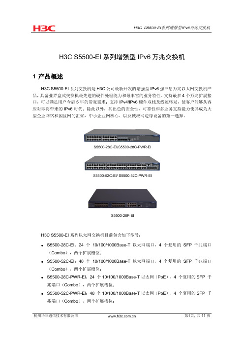
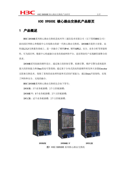
H3C S9500E系列核心路由交换机包含如下型号:S9505E:5个业务板插槽,2个主控板插槽;S9508E-V:8个业务板插槽,2个主控板插槽;S9512E:12个业务板插槽,2个主控板插槽。
S9505E S9508E-V S9512E图1H3C S9500E系列核心路由交换机2 产品特点●创新的体系架构保障业务的高可靠S9500E采用了创新的硬件设计,通过独立的控制引擎、检测引擎、维护引擎为系统提供强大的控制能力和50ms的高可靠保障。
独立的控制引擎,提供强大的主控CPU,轻松处理各种协议报文及控制报文,并支持协议报文精细控制,为系统提供完善的抗协议报文攻击的能力;独立的检测引擎,提供高可靠和高性能的FFDR(Fast Fault Detection and Restoration-快速故障检测及恢复)CPU系统,该CPU系统专门用于BFD、OAM等快速故障检测,并与控制平面的协议实行联动,支持快速保护切换和快速收敛,可以实现50ms的故障检测,保障业务不中断;独立的维护引擎,智能化的EMS(Embedded Maintenance Subsystem-嵌入式维护子系统)CPU系统,该CPU系统支持电源智能管理,可以支持单板顺序上电(降低单板同时上电带来的电源冲击,提高设备寿命,降低电磁辐射,降低系统功耗),设备在线状态检查。
h3c全系列交换机介绍 PPT

课程目标
学习完本课程,您应该能够:
了解并掌握H3C 交换机 产品特点 了解如何引导交换机需求及H3C 交换
机方案 了解并掌握H3C竞争优势
目录
H3C 交换机产品
概述 高端交换机 千兆交换机 百兆交换机
交换机 方案部署 友商竞争分析一览表
H3C交换机发展之路
性价比最高 同样性能价格仅为思科50%左右
千兆接入价格低于思科百兆
H3C 全系列千兆交换机产品线简介
应用场景:
S5800/S5810/S5820X系列
➢1000-2000人规模园区网汇聚 ➢500~800人中型企业核心
➢数据中心网络
S5500-EI系列
S5600系列
应用场景: ➢500~1000人规模园区网汇聚 ➢300~500人中型企业核心 ➢数据中心网络
应用场景: ➢300~500人规模园区汇聚 ➢300人以内小型企业核心
S5100-EI系列
S5100-SI系列
S5500-SI系列
应用场景: ➢智能安全千兆接入 ➢网吧/办公室小型核心
S5800/S5810/S5820X系列产品一览
产品定位一:数据中心接入
千兆服务器 (End of Row)
千兆服务器 (Top of Rack)
H3C数据中心交换机产品
核心与汇聚
H3C S7500E系列
H3C S9500E系列
H3C S12500系列
机架与接入
H3C S5600系列
H3C S5500系列
H3C S5800/S5810/S5820X系列
H3C LAN交换机产品
核心路由 交换机
汇聚交换机
智能二层/三层 交换机
H3C交换机产品及技术概述

S3600EI
S3610
S3600SI
S3100SI
3
E系列教育专用交换机
E328/E352
E126A/E152 E126-SI
智能弹性接入交换机
• 基本三层功能(静态/RIP) • 24/48*10/100/M • +(2SFP+2GT)/4SFP • IRF弹性堆叠扩展 • 8个硬件队列 •ARP入侵检测 •SP/WRR/WFQ队列调度 •4K VALN •64K带宽粒度
千兆接入交换机
•无风扇静音设计 •24*10/100M+2GT(2SFP) •4个硬件队列 •WFQ队列调度 •256VLAN •64K带宽粒度 •WEB网管
定位
• 普教/职教园区网接入 • 桌面/工作组交换机
4
目录
H3C交换机产品概况 H3C S9500核心交换机介绍 H3C S7500E多业务交换机介绍 H3C S7500高端交换机介绍 H3C 千兆交换机介绍 H3C 百兆交换机介绍
H3C S9500系列产品家族
S9508V
S9505
S9508
S9512
S9505 S9508/S9508V
S9512
基本特性
7插槽,2个主控插槽,5个业务插槽 交换容量:300G/600G 转发性能:178Mpps /357Mpps
10插槽,2个主控插槽,8个业务插槽 交换容量:480G/960G 转发性能:285Mpps /571Mpps
☼S9512有两款引擎,分别能发挥出720G和1.44T的交换能力
3. 包转发能力:
₪ 它是指每秒钟交换机整机所能转发的数据包数量,以 太网以64字节的最小包为标准
H3C S9500E 系列路由交换机 IRF与FW ACG IPS插卡典型配置指导

H3C S9500E 系列路由交换机 IRF与FW ACG IPS插卡典型配置指导关键词:IPS、ACG、FW、典型配置指导摘要:介绍在95E堆叠下,FW&ACG&IPS插卡的推荐组网应用方案及典型配置指导。
缩略语:目录1 特性简介 (3)2 应用场合 (5)3 注意事项 (5)4 配置举例 (5)4.1 组网需求 (5)4.2 配置思路 (8)4.3 软件版本 (8)4.4 配置步骤 (10)4.4.1 配置S9500E (10)4.4.2 配置FW (30)4.4.3 配置IPS/ACG (31)4.4.4 OAA定位参考 (32)4.4.5 验证结果 (33)5 相关资料 (38)5.1 相关协议和标准 (38)5.2 其它相关资料 (38)1 特性简介当今网络世界,对网络设备的要求不再仅仅是传统的路由器和交换机提供的数据转发能力,更要求网络设备支持各种各样的应用。
而任何一家独立的技术厂商都很难同时提供客户所要求的所有服务。
所以,一种开放的架构——OAA,能够让众多不同厂商生产的设备和软件集成在一起,像一台设备那样工作,为客户提供一体化的解决方案。
基于这种理念,我司提出了OAA体系规范,H3C S9500E产品正是基于OAA规范开发了一系列应用业务方面的插卡,如无线插卡、安全插卡、防火墙插卡等。
OAA基本的体系结构如图1所示。
图1 OAA体系结构示意图从图中我们看到,OAA体系中,从硬件结构上看,可以分成三部分:路由交换部件、独立业务部件、接口连接部件。
其中,路由交换部件就是路由器和交换机的主体部分,这部分有着完整的路由器或交换机的功能,也是用户管理控制的核心;独立业务部件则是可以开放给第三方合作开发的主体,主要用来提供各种独特的业务服务功能;接口连接部件则是路由交换接部件和独立业务部件的接口连接体,通过这个部件将两个不同厂商的设备连接在一起,以形成一个统一的产品。
对于不同体系结构的产品,路由交换部件本身是存在差异的,如集中式的设备和分布式设备,体系结构上存在差异。
H3C 全系列交换机介绍胶片(20121115)

数据中心,高性能计算,大企业的核心,
面向高密度万兆、和超高密度千兆的应用 产品形态:
S12508(8个业务槽),S12518(18个业务槽)
每槽位可以支持48口千兆(光/电),4/8/32口万兆
5
H3C S12500系列主要特色
先进的CLOS多级多平面交换网架构
CLOS多级多平面交换架构,提供13.32T的交换容量 动态路由信元交换技术实现内部严格无阻塞 单机576个万兆端口接入密度
S5500-SI
百 兆
S3100-SI
S3100-EI
ACL,端口绑定, 防ARP…
S3600-SI
静态路由,RIP
S3600-EI
静态路 由,RIP,OSPF
S3610
L2-
L2+
L3-
L3+
V5平台
L2
L3
V3平台
14
ห้องสมุดไป่ตู้
H3C 全系列千兆交换机产品线简介
应用场景: S5800/5820X/5830系列
48端口千兆电接口板
48端口千兆光接口板
4端口万光接口板
8端口万光接口板
32端口万光接口板
8
S10500-新一代核心交换机
S10504
S10508
S10508-V
S10512
业界首款支持多级交换架构的园区网多业务核心交换机
业界首款支持四框虚拟化的核心交换机
业界首款支持线速40GE接口的核心交换机 业界最全的一体化业务平台
10
H3C S9500E 产品一览
槽位数量
交换容量 包转发能力 引擎冗余
5
720G/1.92T 360Mpps 支持
4 H3C 9500E系列交换机产品系统概述(山东电力培训使用)

H3C 9500E系列交换机产品系统概述ISSUE 1.0日期: 密级: 杭州华三通信技术有限公司 PDF 文件使用 "pdfFactory Pro" 试用版本创建 n 课程目标学习完本课程,您应该能够:n 了解9500E系列交换机型号和硬件结 构 n 了解S9500E系列交换机主控板和业 务接口板 n 掌握S9500E系列交换机主要软件特 性及应用PDF 文件使用 "pdfFactory Pro" 试用版本创建 ÿá 目录n S9500E交换机概述 n S9500E交换机体系结构及单板介绍 n S9500E 增强特性及主要应用PDF 文件使用 "pdfFactory Pro" 试用版本创建 全球最全面的交换机产品线NEW数据中心路 由交换机 H3C S12518NEWH3C S12508NEW核心路由 交换机H3C S7500E 全千兆智能 交换机H3C S9500H3C S9500ENEWH3C S5100SI/EI H3C S5500SI/EI H3C S5800系列智能二层/三层 交换机 H3C S3100SI/EI PDF 文件使用 "pdfFactory Pro" 试用版本创建 H3C S3600SI/EIH3C S3610H3C E系列 4目录n S9500E交换机概述 n S9500E交换机体系结构及单板介绍 n S9500E 增强特性及主要应用PDF 文件使用 "pdfFactory Pro" 试用版本创建 S9500E系列交换机产品定位l H3C S9500E是当前S9500的升级产品,主要硬件架构基 于S9500,接口板采用升级版ASIC芯片,软件平台采用 ComwareV5平台。
l 主要定位于以下应用: à大型城域网的汇聚层,小型城域网的核心层 à大型数据中心汇聚层,中小型数据中心核心层 à大型企业网及园区网的网络核心与汇聚层注:S9500E交换机所有单板与S9500交换机单板不通用。
H3CS9500交换机QoS报文重定向功能的配置

H3CS9500交换机QoS报⽂重定向功能的配置H3C S9500交换机QoS报⽂重定向功能的配置⼀、组⽹需求:报⽂重定向就是改变转发的报⽂的输出⽅向,将其输出到CPU、其他端⼝、其他IP地址或其他单板。
S9500通过流分类重定向到IP下⼀跳实现了策略路由,可以根据报⽂头的其他信息进⾏路由。
由于策略路由的配置是静态的,所以,当配置中的下⼀跳不可⽤时,报⽂将被丢弃。
S9500⽀持配置两个下⼀跳。
以下组⽹图中,公司交换机通过S9500连接到服务提供商设备,⼀条是千兆链路,⽹关为20.20.20.1;另外⼀条是百兆链路,⽹关为20.20.30.1。
公司要求千兆链路只传送IP优先级为4、5、6、7的⾼优先级报⽂,⽽其它低优先级报⽂则使⽤百兆链路连接到服务提供商。
⼆、组⽹图:报⽂重定向典型组⽹图三、配置步骤:软件版本:S9500交换机全系列软件版本硬件版本:S9500交换机全系列硬件版本1)配置VLAN20、VLAN30及虚接⼝地址,使S9500能ping通服务提供商的⽹关,并把相应端⼝加⼊VLAN中[S9500]vlan 20[S9500-vlan20]port GigabitEthernet 9/2/1[S9500]interface Vlan-interface 20[S9500-Vlan-interface20]ip address 20.20.20.2 255.255.255.0[S9500]vlan 30[S9500-vlan30]port Ethernet 3/1/17[S9500]interface Vlan-interface 30[S9500-Vlan-interface30]ip address 20.20.30.2 255.255.255.02)配置匹配IP优先级的流模板并应⽤在端⼝上[S9500]flow-template user-defined slot 9 ip-precedence[S9500]interface GigabitEthernet 9/1/1[S9500-GigabitEthernet9/1/1]flow-template user-defined3)配置ACL规则3000和3100[S9500]acl number 3000[S9500-acl-adv-3000]rule 0 permit ip precedence 7[S9500-acl-adv-3000]rule 1 permit ip precedence 6[S9500-acl-adv-3000]rule 2 permit ip precedence 5[S9500-acl-adv-3000]rule 3 permit ip precedence 4[S9500]acl number 3100[S9500-acl-adv-3100]rule 0 permit ip precedence 3[S9500-acl-adv-3100]rule 1 permit ip precedence 2[S9500-acl-adv-3100]rule 2 permit ip precedence 1[S9500-acl-adv-3100]rule 3 permit ip precedence 04)在端⼝下应⽤规则[S9500]interface GigabitEthernet 9/1/1[S9500-GigabitEthernet9/1/1]traffic-redirect inbound ip-group 3000 next-hop 20.20.20.1[S9500-GigabitEthernet9/1/1]traffic-redirect inbound ip-group 3100 next-hop 20.20.30.1四、配置关键点:1)可以配置两个下⼀跳,当第⼀跳不⽣效后,经过⼤约20秒后切换到第⼆跳,当第⼀跳恢复后再切换回来;2)B类、C类、CA类业务板不⽀持重定向到nested-vlan、modified-vlan;3)CA类单板不⽀持重定向到NAT业务板;4)重定向配置仅对访问列表中动作为permit的规则有效;5)当报⽂被重定向到CPU后,将不再正常转发。
H3CS5500-EI系列以太网交换机操纵说明材料

目录第1章登录以太网交换机.......................................................................................................1-11.1 登录以太网交换机方法简介................................................................................................1-11.2 用户界面简介.....................................................................................................................1-11.2.1 交换机支持的用户界面............................................................................................1-11.2.2 交换机用户界面编号................................................................................................1-11.2.3 用户界面公共配置....................................................................................................1-2第2章通过Console口进行本地登录......................................................................................2-12.1 通过Console口进行本地登录简介......................................................................................2-12.2 通过Console口登录交换机.................................................................................................2-12.3 配置Console口登录方式的属性..........................................................................................2-32.3.1 配置Console口登录方式的公共属性........................................................................2-32.3.2 不同认证方式下Console口登录方式的属性配置......................................................2-42.4 认证方式为None时Console口登录方式的配置..................................................................2-52.4.1 配置过程..................................................................................................................2-52.4.2 配置举例..................................................................................................................2-72.5 认证方式为Password时Console口登录方式的配置...........................................................2-82.5.1 配置过程..................................................................................................................2-82.5.2 配置举例................................................................................................................2-102.6 认证方式为Scheme时Console口登录方式的配置............................................................2-122.6.1 配置过程................................................................................................................2-122.6.2 配置举例................................................................................................................2-14第3章通过Telnet进行登录....................................................................................................3-13.1 通过Telnet进行登录的简介................................................................................................3-13.1.1 配置Telnet登录方式的公共属性...............................................................................3-13.1.2 不同认证方式下Telnet登录方式的配置....................................................................3-23.2 认证方式为None时Telnet登录方式的配置.........................................................................3-33.2.1 配置过程..................................................................................................................3-33.2.2 配置举例..................................................................................................................3-53.3 认证方式为Password时Telnet登录方式的配置..................................................................3-63.3.1 配置过程..................................................................................................................3-63.3.2 配置举例..................................................................................................................3-73.4 认证方式为Scheme时Telnet登录方式的配置.....................................................................3-93.4.1 配置过程..................................................................................................................3-93.4.2 配置举例................................................................................................................3-113.5 Telnet配置环境搭建.........................................................................................................3-133.5.1 通过终端Telnet到以太网交换机.............................................................................3-133.5.2 通过以太网交换机Telnet到以太网交换机..............................................................3-14第4章通过Console口利用Modem拨号远程登录...................................................................4-14.1 通过Console口利用Modem拨号进行远程登录简介...........................................................4-14.2 网络管理员端的相关配置...................................................................................................4-14.3 交换机端的相关配置..........................................................................................................4-14.3.1 与交换机直接相连的Modem上的配置.....................................................................4-14.3.2 交换机的相关配置....................................................................................................4-24.4 通过Modem拨号搭建配置环境...........................................................................................4-2第5章通过WEB网管登录......................................................................................................5-15.1 通过WEB网管登录简介......................................................................................................5-15.2 WEB配置环境搭建.............................................................................................................5-15.3 关闭/启动WEB Server........................................................................................................5-25.4 WEB用户显示....................................................................................................................5-3第6章通过NMS登录.............................................................................................................6-16.1 通过NMS登录简介.............................................................................................................6-16.2 通过NMS方式登录组网结构...............................................................................................6-1第7章 Telnet业务报文指定源IP.............................................................................................7-17.1 Telnet业务报文指定源IP简介.............................................................................................7-17.2 配置Telnet业务报文指定源IP.............................................................................................7-17.3 配置Telnet业务报文指定源IP显示......................................................................................7-2第8章对登录用户的控制.......................................................................................................8-18.1 简介....................................................................................................................................8-18.2 配置对TELNET的控制.......................................................................................................8-18.2.1 配置准备..................................................................................................................8-18.2.2 通过源IP对TELNET进行控制..................................................................................8-18.2.3 通过源IP、目的IP对TELNET进行控制....................................................................8-28.2.4 通过源MAC地址对TELNET进行控制......................................................................8-38.2.5 配置举例..................................................................................................................8-38.3 通过源IP对网管用户进行控制............................................................................................8-48.3.1 配置准备..................................................................................................................8-48.3.2 通过源IP对网管用户进行控制..................................................................................8-48.3.3 配置举例..................................................................................................................8-58.4 通过源IP对WEB用户进行控制...........................................................................................8-68.4.1 配置准备..................................................................................................................8-68.4.2 通过源IP对WEB用户进行控制.................................................................................8-68.4.3 强制在线WEB用户下线...........................................................................................8-7 8.4.4 配置举例..................................................................................................................8-7第1章登录以太网交换机1.1 登录以太网交换机方法简介S5500-EI系列以太网交换机的登录,可以通过以下几种方式实现:z通过Console口进行本地登录z通过以太网端口利用Telnet进行本地或远程登录z通过Console口利用Modem拨号进行远程登录z通过WEB网管登录z通过NMS(Network Management Station,网管工作站)登录1.2 用户界面简介1.2.1 交换机支持的用户界面S5500-EI系列以太网交换机支持两种用户界面:AUX用户界面、VTY用户界面。
01.S7500E系列交换机产品介绍(内部使用).3.0

4
75E“七剑客”众生像-S7510E
16U横插板 一体化机箱 2个主控板槽位, 提供冗余备份 • 10个业务板 槽位,支持热 插拔; • 最大支持 502GE/480F E/24*10GE
• 整机交换容量 最大1152G; • 背板容量2.4T 电源1+1备份
风扇自动调速, 低功耗、低噪声
21U横插板一体 化机箱,纵向风 道、散热效率高 风扇自动调速, 低功耗、低噪声
2个主控板槽位, 提供冗余备份
• 6个业务板槽 位,支持热插 拔; • 最大支持 312GE/288FE /14*10GE
• 整机交换容量 最大768G; • 背板容量1.6T
电源1+1备份
S7506E-V按照北美 NEBS规范,针对防火、 防震和散热等方面进 行了专业设计,可以 满足运营级的要求;
S7500E众生像 Salience VI系列引擎 S7500E的业务板系列 S7500E的框架组件
15
S7500E的引擎-Salience VI系列
Salience VI系列引擎是S7500E交换机的控制管理平面和 交换网的核心,该系列引擎包括10种类型
S7503E-S专用引擎, 1台S7503E-S可配臵1块这种引擎; 提供大容量交换网,同时提供24个千兆SFP光口,其中8个端口为光 电Combo口。
24个GE端口
Байду номын сангаас
Console口 10/100M管理网口
26
S7503E-S的引擎- LSQ1CGV24PSC
S7503E-S专用引擎, 1台S7503E-S可配臵1块这种引擎; 提供大容量交换网,同时提供24个千兆电口,其中4端口为光电 Combo口。
H3C S5500 EI系列以太网交换机产品彩页(070413)

H3C S5500-EI系列以太网交换机产品1 产品简介H3C S5500-EI系列交换机是全千兆强三层以太网交换机产品,具备丰富的业务特性,支持硬件IPv6转发以及最多4个10GE扩展接口。
S5500-EI系列千兆以太网交换机特别适合作为需要高带宽、高性能和高扩展性的中小企业网核心、大型企业网络和园区网的汇聚和接入以及数据中心的服务器接入设备。
H3C S5500-EI系列目前可以提供:∙S5500-EI系列硬件支持IPv4和IPv6双协议,并支持多种三层协议;∙产品系列齐全,每款产品均支持两个上行模块,最大可以支持到4×10GE上行,扩展性强,充分保护投资;∙POE(Power Over Ethernet)功能,通过双绞线向远端下挂PD设备供电;∙更强ACL功能,可以实现基于VLAN的ACL下发以及基于出端口和入端口的ACL(Ingress/ Egress ACL)功能,便于网络规划和管理;∙RRPP(Rapid Ring Protection Protocol)环网技术保护协议,具备更快收敛速度和收敛时间,使网络更加可靠;∙百兆和千兆光模块自适应,使应用更加方便;∙SFlow功能,可以对出入方向的报文按比例随机抽样,灵活实现报文采集;H3C S5500-EI系列以太网交换机目前包含如下型号:●S5500-28C-EI:24 个10/100/1000以太网端口,4 个SFP 千兆位以太网端口(Combo),两个扩展槽位;支持AC和DC电源双输入;●S5500-52C-EI:48 个10/100/1000以太网端口,4 个SFP 千兆位以太网端口(Combo),两个扩展槽位;支持AC和DC电源双输入;●S5500-28F-EI:24个100M/1000M SFP以太网光口,8个10/100/1000千兆位以太网端口(Combo),两个扩展槽位;支持两个互为备份的可插拔AC/DC电源;●S5500-28C-PWR-EI:24 个10/100/1000以太网端口,带PoE功能,4 个SFP 千兆位以太网端口(Combo),两个扩展槽位;支持AC和DC电源双输入;● S5500-52C-PWR-EI:48 个10/100/1000以太网端口,带PoE功能,4 个SFP 千兆位以太网端口(Combo),两个扩展槽位;支持AC和DC电源双输入;S5500-28C-EI/S5500-28C-PWR-EI前后面板图S5500-52C-EI/ S5500-52C-PWR-EI前后面板图S5500-28F-EI前后面板图2 产品特点●高扩展性,保护投资随着用户端速度不断提高,用户最终会使集群千兆链路达到饱和,而能够拥有多条10GE链路将是我们的未来发展方向。
H3C S9500E Series 路由器交换机快速启动指南说明书

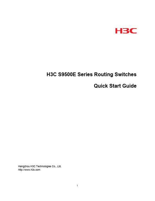
H3C S9500E Series Routing SwitchesQuick Start GuideHangzhou H3C Technologies Co., Ltd.Copyright © 2003-2010, Hangzhou H3C Technologies Co., Ltd. and its licensorsAll Rights ReservedNo part of this manual may be reproduced or transmitted in any form or by any means without prior written consent of Hangzhou H3C Technologies Co., Ltd.TrademarksH3C, , Aolynk, , H3Care, , TOP G, , IRF, NetPilot, Neocean, NeoVTL, SecPro, SecPoint, SecEngine, SecPath, Comware, Secware, Storware, NQA, VVG, V2G, V n G, PSPT, XGbus, N-Bus, TiGem, InnoVision and HUASAN are trademarks of Hangzhou H3C Technologies Co., Ltd.All other trademarks that may be mentioned in this manual are the property of their respective owners.NoticeThe information in this document is subject to change without notice. Every effort has been madein the preparation of this document to ensure accuracy of the contents, but all statements, information, and recommendations in this document do not constitute the warranty of any kind, express or implied.Environmental ProtectionThis product has been designed to comply with the requirements on environmental protection. Thestorage, use, and disposal of this product must meet the applicable national laws and regulations.S9500E Installation Quick Start Guide About this guideThis guide provides steps for basic installation and configuration for the S9500E series. Furtherinformation, such as optional installation and configuration procedures are available in the S9500E Installation Guide.Product overviewThe S9500E series include the following models:•S9505E:The S9505E provides five line processing unit (LPU) slots and two MPU slots, horizontal•S9508E-V:The S9508E-V provides eight LPU slots and two main processing units (MPU) slots, vertical•S9512E:The S9512E provides twelve LPU slots and two MPU slots, horizontal Prepare for installationSafety recommendationsTo avoid possible bodily injury and equipment damage, read the following safety recommendations before installing an H3C S9500E switch. Note that the recommendations donot cover every possible hazardous condition.•Take adequate safety measures to avoid injury and switch damage.•Make sure that the ground is dry and flat and anti-slip measures are in place.•Keep the chassis clean and dust-free.•Do not place the switch in a moist area and avoid liquid surrounding the switch.•Keep the chassis and installation tools away from walkways.•Multiple people should move the switch and heavy components.Examine the installation siteThe H3C S9500E series can only be used indoors. Make sure that the floor can support theweight of the switch and its accessories.To ensure the normal operation of the switch, ensure that the following elements meet requirements described in “Preparing for installation” in the S9500E Installation Guide: roomtemperature; humidity, cleanness; EMS; grounding; power supply; space; and cabinet-mounting.Installation toolsTable 1 Required installation toolsCategory ToolMeasure andlineation tools Long tape, ruler (1 meter in length), gradienter, marking pen, powder marker, pencilDrills One percussion drill, several drill bits, one vacuum cleanerFastening tools Plain screwdriver P4 - 75 mmCross-head screwdriver P1 – 100 mm, P2 – 150 mm and P3 – 250 mm Box wrench M5Ring spanner M6Double ring spanner (10-12) or open ended spanner (10-12)Small tools Sharp-nose pliers, diagonal pliers, vices, hand-held electric drill, file, handsaw, crowbar, rubber hammerAuxiliary tools Brush, tweezers, paper knife, hand bellows, electric iron, solder wire, fork, ladderSpecial tools ESD-preventive wrist strap, cable stripper, crimping pliers, RJ-45 crimping pliers, wire punch-down toolMetersMultimeter, 500 V Meg-ohmmeter (used for measuring the insulation resistance), errordetector, optical power meter, earth resistance testerThe instruments and tools are not shipped with the S9500E series.Install the switchThis guide provides basic installation steps. See the S9500E Installation Guide for comprehensiveprocedures for installing the switch.To avoid bodily injury, do not touch any wire, terminal, or part marked with a high-voltage hazard sign.Installation workflowFigure 1 Installation flow of the switchInstall the switch on a rackThis S12500Quick Start Guide provides steps to install the switch on a rack. The S12500 Installation Guide also provides steps to install the S12500 on a workbench.This section explains how to install mounting and cable management brackets for the S9505E and S9512E. See the S9500E Installation Guide for steps on installing the mounting brackets and cable management brackets for the S9508E-V.Preparation•Check that the cabinet is well grounded and secured. Make sure the layout inside the rack for the switch installation is done and there is no debris left inside or around the cabinet.•There is enough space around the cabinet for heat-dissipation.Install the mounting brackets and cable management brackets for the S9505E and S9512E1.Install the cable management brackets on the mounting brackets with tapping screws.2.Attach the mounting brackets onto the left and right sides of the switch, as shown in Figure2.Figure 2 Install the mounting brackets and cable management brackets(1) Mounting brackets (2) Cable management bracket (3) Mounting screwsInstall the switch in the rack1.Place the switch on the support tray and slide the switch along the slide rails until themounting brackets on the switch reach the rack posts.e mounting screws to fix the mounting brackets to the rack posts.Connect the PGND cableThe switch must be well grounded. The resistance reading between switch chassis and the ground must be less than 1 ohm.Connection in generic grounding environmentThis section describes connecting in a generic grounding environment. See the S9500 Installation Guide for methods for grounding the switch in different grounding environments.1.Remove the screw from the grounding hole on the switch chassis.2.Put the supplied OT terminal of the PGND cable on the grounding screw.3.Insert the grounding screw into the grounding hole and screw it down.4.Connect the other end of the PGND cable to the grounding strip of the cabinet.Install a power systemSee the S9500 Installation Guide for instructions for installing a power system.Install a cardBefore installing a card, follow these preparations.1.Put on an ESD-preventive wrist strap and make sure that the wrist strap is properlygrounded.2.Remove the blank panel (if any) from the slot to be used.3.Prepare the card to be installed.Follow these steps to install a card:1.Move the ejector levers outwards, hold the module by the handle, and push the board intothe slot along slide rails slowly.2.Push the ejector levers inward to ensure a firm contact between the board and thebackplane.3.Position the screws into the holes and fasten them with a screwdriver to fix the board. Install a fan trayThis guide provides steps to install a fan tray for an S9505E or S9512E. See the S9500E Installation Guide for steps to install a fan tray for an S9508E-V1.Put on an ESD-preventive wrist strap and make sure the wrist strap is well grounded.2.Push the fan tray along the guide rails until it has a good contact with the backplane.3.Fasten the screws on the fan tray panel.Log in to the switchConnect the console cableThis section provides information on connecting the console cable. See the S9500E Installation Guide for information on connecting the AUX cable, network cables and optical fibers.1.Plug the DB-9 female connector of the console cable to the serial port of the PC or terminalwhere the switch is to be configured.2.Connect the RJ-45 connector of the console cable to the console port of the switch.Set up a configuration environmentunch a terminal emulation utility. Select Start > Programs > Accessories >Communications > HyperTerminal to access the HyperTerminal window. Click inthe window to set up a new connection. The Connection Description dialog boxappears.2.Enter the name of the new connection in the Connection Description dialog box, andclick OK. Select a port from the Connect using drop-down list.3.Set serial port parameters. Set the bits per second to 9600, data bits to 8, parity to None,stop bits to 1, and flow control to None.4.Click OK to enter the HypterTerminal window,5.Select File > Properties in the HyperTerminal window to access the Properties window.Click Settings in the Window, select VT100 for terminal emulation, and click OK. Power on the switchTo power on the switch, perform the following steps:1.Turn on the power switch of the power source providing power to the switch.2.Turn on the power switch of the PWR on the switch.H3C recommends that you check the following conditions after the switch is powered on:•The cooling system is working (you can hear the noise caused by fan rotation and feel air exhausted out.)•All the system LEDs on the MPUs function normally.•All the LEDs on the PSUs function normally. Input LED IN and output LED OUT is on, and the fault LED FAIL is off.Verify the installationMake sure that you have turned off the power before checking the installation to avoid bodily injury and device damage.After installing the switch, verify the installation against the following list. For the successful installation, all items must be normal.Table 2 Installation checklistItem ResultRemarks Yes NoThe PGND cable is correctly grounded.Fan trays are correctly installed and have a tight contact with the backplane.PSUs are correctly installed and have a good contact with the frames.Power cords are correctly connected.MPUs are correctly installed and have a good contact with the backplane.Item ResultRemarks Yes NoInterface cards are correctly installed and have a good contact with the backplane.The console cable is correctly connected.。
H3CS9500交换机RPR三层组网功能的配置

H3CS9500交换机RPR三层组网功能的配置H3C S9500交换机RPR(Route Protocol Readiest)三层组网功能是在交换机上配置路由协议,使其能够实现三层(网络层)的功能,如路由转发、路由表管理、子网划分等。
以下是H3C S9500交换机RPR三层组网功能的详细配置步骤。
1.配置三层组网基本设置:(1)设置交换机主机名:sysname SwitchA(2)配置管理地址:interface Vlan-interface 1ip address 192.168.1.1 255.255.255.0quit(3)开启SSH或Telnet远程登录:ssh server enabletelnet server enable2.配置路由协议:(1)配置静态路由:ip route-static 0.0.0.0 0.0.0.0 192.168.1.254(2)配置动态路由:ripnetwork 10.0.0.0quitOSPF协议配置:ospfarea 0.0.0.0network 10.0.0.0 0.0.0.255quit3.配置接口:(1)配置物理接口:interface GigabitEthernet1/0/1port link-type accessport default vlan 10quit(2)配置虚接口:interface Vlan-interface 10ip address 10.0.0.1 255.255.255.0quit(1)创建VLAN:vlan 10vlan 20quit(2)配置接口VLAN绑定:interface GigabitEthernet1/0/1port link-type hybridport hybrid vlan 10 untaggedquit(3)配置虚接口VLAN绑定:interface Vlan-interface 10vlan-type dot1q 10quit5.配置ACL(访问控制列表):(1)创建ACL:acl number 2000rule permit ip source 10.0.0.0 0.0.0.255 destination 192.168.1.0 0.0.0.255quit(2)应用ACL:interface GigabitEthernet1/0/1traffic-filter inbound acl 2000quit6.配置DHCP(动态主机配置协议):(1)启用DHCP服务:dhcp enable(2)配置DHCP池:interface GigabitEthernet1/0/1dhcp server ip-pool Pool1quit(3)配置DHCP地址池:ip pool Pool1network 192.168.1.0 mask 255.255.255.0 gateway-list 192.168.1.1quit以上是H3CS9500交换机RPR三层组网功能的基本配置步骤。
H3C S9500系列核心路由交换机彩页(200810)

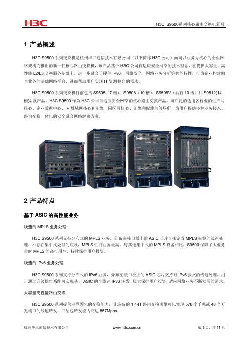
1 产品概述H3C S9500系列交换机是杭州华三通信技术有限公司(以下简称H3C公司)面向以业务为核心的企业网络架构而推出的新一代核心路由交换机,该产品基于H3C公司自适应安全网络的技术理念,在提供大容量、高性能L2/L3交换服务基础上,进一步融合了硬件IPv6、网络安全、网络业务分析等智能特性,可为企业构建融合业务的基础网络平台,进而帮助用户实现IT资源整合的需求。
H3C S9500系列交换机目前包括S9505(7槽)、S9508(10槽)、S9508V(垂直10槽)和S9512(14槽)4款产品。
H3C S9500作为H3C公司自适应安全网络的核心路由交换产品,可广泛的适用各行业的生产网核心、企业数据中心、IP城域网核心和汇聚、园区网核心、汇聚和配线间等场所,为用户提供多种业务接入、路由交换一体化的安全融合网络解决方案。
2 产品特点基于ASIC的高性能业务线速的MPLS业务处理H3C S9500系列支持分布式的MPLS业务,分布在接口板上的ASIC芯片直接完成MPLS标签的线速处理,不存在集中式处理的瓶颈,MPLS性能业界最高。
与其他集中式的MPLS设备相比,S9500保障了大业务量时MPLS的高可用性,持续保护用户投资。
线速的IPv6业务处理H3C S9500系列支持分布式的IPv6业务,分布在接口板上的ASIC芯片支持对IPv6报文的线速处理,用户通过升级操作系统可实现基于ASIC的全线速IPv6转发,极大保护用户投资,适应网络业务不断发展的需求。
大容量高性能路由交换H3C S9500系列提供业界领先的交换能力,其最高的1.44T路由交换引擎可以实现576个千兆或48个万兆端口的线速转发,三层包转发能力高达857Mpps。
融合的网络安全特性集成的安全特性H3C S9500系列产品基于开放的OAA架构,可以集成防火墙模块、IPS模块、ACG应用控制网关模块、AFC异常流量清洗模块、LB负载均衡模块、SSL VPN模块,通过产品的融合实现网络安全一体化的解决方案。
H3C9500E系列交换机产品系统综述

4端口万兆以太网光接口业务板
2端口万兆以太网光接口业务板
16端口万兆以太网光接口业务板 20
S9500E单板介绍-48端口千兆板
LSRM1GP48LEF1 LSRM1GP48LEC1 LSRM1GP48LEB1 LSRM2GV48REB1 LSRM1GT48LEC1 LSRM2GT48LEB1
48端口千兆以太网光接口线速业务板(LC)
9
丰富的业务特性和良好的可扩展能力
支持分布式的MPLS/VPLS业务,提供高品质、安全和多层 次的MPLS VPN解决方案,支持MPLS/VPLS业务的全分布 式转发功能;
支持分布式的IPv6业务,适应网络业务不断发展的需求。 支持高性能组播、组播VPN等业务; 支持URPF,用来防止基于源地址欺骗的网络攻击行为; 基于OAA(Open Application Architecture)机制提供标
全球最全面的交换机产品线
数据中心路 由交换机
H3C S12518
H3C S12508 H3C S12504
核心路由 交换机
H3C S7500E
H3C S9500
H3C S9500E
全千兆智能 交换机
H3C S5100SI/EI H3C S5500SI/EI
H3C S5800系列
智能二层/三层 交换机
Engine
Crossbar
Crossbar
CPU FFDR EMS
智能化的EMS(Embedded Maintenance Subsystem-嵌入式维护子系统) CPU系统,支持 电源智能管理,设备状态检查。
Engine
Crossbar
Crossbar
CPU FFDR EMS
H3C S7500E系列产品技术介绍

机“分身有术”,为关键业务和用
户创造安全空间 n H3C Overlay技术实现虚拟叠加网
络,网络真正随需而动
n 更多令人激动的新特性……
横空出世 独步江湖 n H3C IRF虚拟化技术,园区进
Comw
入网络虚拟化时代 n H3C RRPP快速以太环网技术,
传统园区
业务应用数据
• 基于IEEE 802.1ae • 覆盖1G~10G端口 • 部署方式可灵活调整
SDN网络安全的物理屏障
n SDN网络架构下,通过Macsec硬件加密技 术能够进一步保障关键链路的安全可靠。例 如控制平面和核心数据链路的硬件加密。
云桌面
云桌面
云桌面数据流
传统终端 传统终端 本地应用数据
ü SDN实践先锋
• 支持OPENFLOW 1.3标准 • 支持多控制器(EQUAL模式、主备模式) • 支持Vxlan集中控制模式
上层控制器
RESTful
云计算系统
OpenStack
100G/40G以太网光接口
SOAP
管理监控
Java…
上层应用
H3C ADNET
10G以太网光接口
OpenFlow/南向协议
千兆以太网电/光接口(全球首发)
硬件支持VxLAN线速转发
VxLAN网络
软件特性——全面支持EPON
符合中国电信互通标准
可接入其它厂商符合互通标准的ONU;
增强的PON口功能
支持1:64分光比; 支持FEC功能,增加光路预算; 支持主干光路保护;
灵活多功能的PON业务板
可以根据需要使用不同规格的SFP OLT光模块; 可根据大客户需求定制OLT光模块; PON自带8个GE上行接口,通常情 况下无需增加其它业务板;
H3C S9500ES12500系列交换机上ACGIPS插卡MQC引流典型配置

H3C S9500E&S12500系列交换机上ACG&IPS插卡MQC引流典型配置一、组网需求:某客户购买了两块SecBlade IPS插卡部署在S95E交换机上,为内网提供攻击检测和安全防护,两台交换机运行在IRF模式,外网用户访问服务器的流量经过IPS插卡,内部服务器互访的流量不上IPS插卡,并且两块插卡能实现主备,当其中一块插卡故障以后业务可以迅速切换到另一块插卡。
二、组网图:如上图所示:两台S9505E交换机堆叠,每台交换机上插一块IPS插卡,内部服务器网关部署在交换机上,服务器互访的流量不经过IPS插卡,外部用户防范服务器的流量正常情况下经过IPS-1,当IPS-1故障以后,流量经过IPS-2。
交换机版本:Comware Software, Version 5.20, Release 1238P08IPS插卡版本:i-Ware software, Version 1.10, Ess 2110P10三、配置步骤:交换机上关键配置:#acsei server enable //通过acsei协议对插卡进行时间同步和状态检测,实现主备切换#acl number 3001 //匹配上插卡的流量description Match-ALL-Addressrule 0 permit ipacl number 3002 //匹配上插卡的流量,用于备份description Match-ALL-Addressrule 0 permit ipacl number 3004 //内网互访的流量不上插卡description Match-Internal-Flowrule 0 permit ip destination 192.168.14.0 0.0.0.255rule 5 permit ip destination 192.168.15.0 0.0.0.255rule 10 permit ip destination 192.168.16.0 0.0.0.255rule 15 permit ip destination 192.168.17.0 0.0.0.255rule 20 permit ip destination 192.168.18.0 0.0.0.255#acl number 4000 //匹配广播、组播和ARP报文description Match-Multicast-Broadcast-ARPrule 0 permit dest-mac 0100-0000-0000 ff00-0000-0000rule 5 permit dest-mac ffff-ffff-ffff ffff-ffff-ffffrule 10 permit type 0806 ffff#vlan 1001 to 1008#vlan 4000 //用于IRF的BFD MAD检测description Mad-Detection#traffic classifier Internal-Flow-1 operator andif-match acl 3004traffic classifier Multicast-Broadcast-ARP operator andif-match acl 4000traffic classifier All-Address-1 operator andif-match acl 3001if-match forwarding-layer route //仅将三层转发流量引流traffic classifier All-Address-2 operator andif-match acl 3002if-match forwarding-layer route#traffic behavior Deny-Multicast-Broadcast-ARPfilter denytraffic behavior Redirect-To-IPS-1redirect interface Ten-GigabitEthernet1/4/0/1traffic behavior Redirect-To-IPS-2redirect interface Ten-GigabitEthernet2/4/0/1traffic behavior Allowfilter permit#qos policy Deny-Multicast-Broadcast-ARP //本地产生的组播、广播和ARP报文不上插卡classifier Multicast-Broadcast-ARP behavior Deny-Multicast-Broadcast-ARPqos policy DOWN_STREAMclassifier Multicast-Broadcast-ARP behavior Allow //广播等报文不上插卡classifier All-Address-1 behavior Redirect-To-IPS-1 //流量先上IPS-1classifier All-Address-2 behavior Redirect-To-IPS-2 //IPS-1故障后上IPS-2qos policy UP_STREAMclassifier Multicast-Broadcast-ARP behavior Allowclassifier Internal-Flow-1 behavior Allow //内网互访流量不上插卡classifier All-Address-1 behavior Redirect-To-IPS-1classifier All-Address-2 behavior Redirect-To-IPS-2#interface Vlan-interface1001ip address 192.168.11.254 255.255.255.0#interface Vlan-interface1002ip address 192.168.12.254 255.255.255.0#interface Vlan-interface1004ip address 192.168.14.254 255.255.255.0#interface Vlan-interface1005ip address 192.168.15.254 255.255.255.0#interface Vlan-interface1006ip address 192.168.16.254 255.255.255.0#interface Vlan-interface1007ip address 192.168.17.254 255.255.255.0#interface Vlan-interface1008ip address 192.168.18.254 255.255.255.0#interface Vlan-interface4000 //BFD MAD检测VLANmad bfd enablemad ip address 200.0.0.1 255.255.255.252 chassis 1mad ip address 200.0.0.2 255.255.255.252 chassis 2#interface GigabitEthernet1/2/0/17 //专用于MAD检测的端口,关闭STPport access vlan 4000stp disable#interface GigabitEthernet2/2/0/17port access vlan 4000stp disable#接口上下发MQC:#interface GigabitEthernet1/2/0/1port access vlan 1004qos apply policy UP_STREAM inbound#interface GigabitEthernet1/2/0/2port access vlan 1001qos apply policy DOWN_STREAM inbound#interface GigabitEthernet2/2/0/1port access vlan 1008qos apply policy UP_STREAM inbound#interface GigabitEthernet2/2/0/2port access vlan 1002qos apply policy DOWN_STREAM inbound#S95E与IPS插卡接口配置:#interface Ten-GigabitEthernet1/4/0/1port link-type trunkport trunk permit vlan 1 1001 to 1008 //必须允许VLAN 1通过,否则跨框重定向报文不生效stp disableqos apply policy Deny-Multicast-Broadcast-ARP inbound //防止本地产生的组播、广播、ARP报文从内敛口转发到插卡,S95E&S12500对于本机发出的协议报文,用MQC在outbound方向不能过滤,会导致环路,ospf邻居down等问题,所以需要在inbound方向过滤mac-address max-mac-count 0#interface Ten-GigabitEthernet2/4/0/1port link-type trunkport trunk permit vlan 1 1001 to 1008stp disableqos apply policy Deny-Multicast-Broadcast-ARP inboundmac-address max-mac-count 0#acsei server //配置acsei时间参数,一般保持默认即可acsei timer clock-sync 1 //配置插卡同步时间的间隔,单位分钟,默认5分钟acsei timer monitor 1 //配置对插卡的监控时间间隔,单位是秒,默认5秒#irf-port 1/1port group interface GigabitEthernet1/2/0/15port group interface GigabitEthernet1/2/0/16#irf-port 2/2port group interface GigabitEthernet2/2/0/15port group interface GigabitEthernet2/2/0/16#IPS插卡相关配置(两快IPS插卡的配置一样):1.去使能OAA ACFP Client。
