r3000用户使用手册d
NETGEAR Trek N300 旅行路由器和扩展器 PR2000 快速启动指南说明书
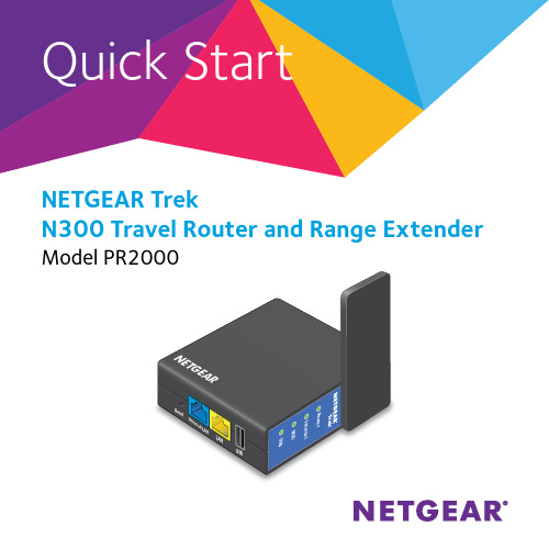
NETGEAR Trek N300 Travel Router and Range Extender WiFi US BU S B L A NGE AR PowerGetting StartedThank you for purchasing the NETGEAR Trek N300 Travel Router and Range Extender PR2000. You can connect your Trek to the Internet by using the Trek in hotspot mode, extender mode, or router mode. Note: You can also use the Trek in bridge mode or AP mode. For more information, see the user manual. You can get the user manual online at or through a link in the Trek’s user interface. For more information about how to access the Trek’s user interface, see View or Change the Trek’s Settings on page 17.Hotspot mode Extender modeRouter modeport.Internet Mode SwitchPut the• Wired. Set the switch to Wired if you want to connect the Trek to the Internet with an Ethernet cable. For example, set the switch to Wired if you want to use the Trek in router mode or AP mode.• Power off. Set the switch to Power off to turn off the Trek. Make sure the switch is set to Power off before plugging the Trek into anelectrical outlet.• Wireless. Set the switch to Wireless to connect the Trek to the Internet with a WiFi connection. For example, set the switch toWireless if you want to use the Trek in hotspot mode, extender mode, or bridge mode.Connection Ports and Reset ButtonThe Trek has the following connection ports and reset button:• Reset button . To reset the Trek to its factory default settings, insert a paper clip into the Reset hole and hold it until the Internet LEDblinks.• Internet/LAN port . When the Internet Mode switch is set to Wired, this port becomes an Internet port. When the switch is set to Wireless, this port becomes a LAN port.• LAN port . A LAN port for any Ethernet-enabled device.•USB port . A USB port for USB storage or USB printer. If the Trek is plugged into an AC wall outlet, the USB port can also be used as a charger.Indicator LEDsMonitor the status of your Trek using the following LEDs:Power LED• Green. The Trek is powered on.• Off. The Trek is powered off.Internet LED• Green. The Trek is connected to the Internet.• Blinking green. One of the following occurred:• The Reset button was pressed longer than fiveseconds.• A firmware upgrade is in progress.• The bandwidth limit was exceeded.• Off. The Trek is not connected to the Internet.WiFi LED• Green. The WiFi radio is operating.• Off. The WiFi radio is off.USB LED• Green. A USB device is connected and ready.• Off. No USB device is connected.Set Up Your Trek¾To set up your Trek:1. Record your Trek’s WiFi network name (SSID) and WiFi password.The SSID and WiFi password are on the sticker near the Internetmode switch. You can write the WiFi settings from the sticker in this space for easy reference.SSID:WiFi password:2. Connect the Trek to a power source.Use one of these options:• AC power connection. Plug the Trek into an AC wall outlet.• Micro USB connection. Connect a micro USB cable to the Trek and to a USB port on another device.AC power connection Micro USB connection3. Rotate the Trek’s cover clockwise to orient the antenna.The WiFi antenna is inside the cover. For best performance, keep the cover vertical when you use your Trek.Use one of these options:• Use the Trek in Hotspot Mode on page 8• Use the Trek in Extender Mode on page 11• Use the Trek in Router Mode on page 14Use the Trek in Hotspot Mode Use the Trek in hotspot mode to connect to a public hotspot. The Trek’s firewall protects your devices from known DoS attacks and port scans from the Internet.CAUTION : Most public WiFi hotspots offer no security. NETGEARrecommends that you do not send personal information over the Internetwhen using a public WiFi hotspot.¾To use the Trek in hotspot mode:1. Connect your Trek to a power source and rotate the antenna.For more information, see Set Up Your Trek on page 62. Set the Internet Mode switch to Wireless.3. Connect your computer or WiFi device to the Trek.You can use an Ethernet cable or connect with WiFi:• For a wired connection, use an Ethernet cable (not included) to connect your computer to the LAN port on the Trek.• To connect with WiFi, use the Trek’s network name (SSID) and WiFi password, which are on the sticker near the Internet Modeswitch. For more information, see Connect Devices to Your Trekwith WiFi on page 16.4. Launch a web browser.5. Enter in the address field of the browser.The Wireless as WAN screen displays, which shows the available WiFi networks.6. If a login screen displays, do the following:a. Enter admin for your user name and password for yourpassword.The BASIC Home screen displays.b. Select Internet.The Wireless as WAN screen displays, which shows the availableWiFi networks.7. Clear the Extend my current wireless router’s range check box.8. Select a radio button next to the WiFi network to which you want toconnect.9. From the Security list, select the WiFi network’s security option.10. In the Password (Network Key) field, type the WiFi network’spassword.11. For the Internet IP Address setting, select one of the following radiobuttons:• Get Dynamically. The Internet service provider (ISP) uses DHCP to assign your IP address. Your ISP automatically assigns theseaddresses.• Use Static IP Address. Enter the IP address, IP subnet mask, and the gateway IP address that your ISP assigned. The gateway isthe ISP’s gateway to which your Trek connects.12. To be able to use these settings again without having to reenter them,select the To save a name for profile check box and in the fieldprovided, type a name for the profile.Create a descriptive name for the profile to help you remember thesettings. For example, if you visit a hotel frequently, you might use the hotel name as the profile name.13. Click the Apply button.It might take up to two minutes before the Trek connects to the WiFi network.14. If your computer or WiFi device disconnects from the Trek, reconnect your computer or WiFi device to the Trek.Use the Trek in Extender ModeUse the Trek in extender mode to boosting an existing WiFi signal and enhancing the overall signal quality over long distances. NETGEAR recommends that you use the Trek in extender mode when a wireless device is in a dead zone where the connection to your existing WiFi routeris poor or nonexistent.¾1. Place your Trek in the same room as your WiFi router.Note: Proximity to the WiFi router is required only during the initial setup process.2. Connect your Trek to a power source and rotate the antenna.For more information, see Set Up Your Trek on page 6.3. Set the Internet Mode switch to Wireless.4. Connect your computer or WiFi device to the Trek.You can use an Ethernet cable or connect with WiFi:• For a wired connection, use an Ethernet cable (not included) to connect your computer to the LAN port on the Trek.• To connect with WiFi, use the Trek’s, network name (SSID) and WiFi password, which are on the sticker near the Internet Modeswitch. For more information, see Connect Devices to Your Trekwith WiFi on page 16.5. Launch a web browser.6. Enter in the address field of the browser.The Wireless as WAN screen displays, which shows the available WiFi networks.7. If a login screen displays, do the following:a. Enter admin for your user name and password for yourpassword.The BASIC Home screen displays.b. Select Internet.The Wireless as WAN screen displays, which shows the availableWiFi networks.8. Select the Extend my current wireless router’s range check box.9. Select a radio button next to a WiFi network you want to connect to.10. From the Security list, select the WiFi network’s security option.11. In the Password (Network Key) field, type the WiFi network’spassword.12. To be able to use these settings again without having to reenter them,select the To save a name for profile check box and in the fieldprovided, type a name for the profile.Create a descriptive name for the profile to help you remember the settings. For example, if you might use Extender Mode as the name for your extender profile settings.13. Click the Apply button.It might take up to two minutes before the Trek connects to the WiFi network.14. Unplug the Trek and move it to a new location closer to the area witha poor WiFi signal.The location that you choose must be within the range of yourexisting WiFi router network.15. Connect your Trek to a power source and rotate the antenna.For more information, see Set Up Your Trek on page 616. If your computer or WiFi device disconnects from the Trek, reconnect your computer or WiFi device to the Trek.Use the Trek in Router ModeYou can connect the Trek to a DSL or cable modem and use the Trek as arouter.¾To use the Trek in router mode:1. Connect you Trek to a power source and rotate the antenna.For more information, see Set Up Your Trek on page 62. Connect your DSL or cable modem to the Internet/LAN port on theTrek with an Ethernet cable.3. Set the Internet Mode switch to Wired.4. Connect your computer or WiFi device to the Trek.You can use an Ethernet cable or connect with WiFi:• For a wired connection, use an Ethernet cable (not included) to connect your computer to the LAN port on the Trek.• To connect with WiFi, use the Trek’s network name (SSID) and WiFi password, which are on the sticker near the Internet Modeswitch. For more information, see Connect Devices to Your Trekwith WiFi on page 16.5. Launch a web browser.6. Enter in the address field of the browser.NETGEAR genie displays.7. If a login screen displays, do the following:a. Enter admin for your user name and password for yourpassword.The BASIC Home screen displays.b. Select ADVANCED > Setup Wizard.The Setup Wizard screen displays.8. Follow the onscreen instructions.NETGEAR genie guides you through connecting the Trek to theInternet.Connect Devices to Your Trek with WiFiTo use WiFi to connect your computer or WiFi device (such as a smartphone or gaming device) to your Trek’s WiFi network, use the Trek’s network name (SSID) and WiFi password on the sticker near the Internet Mode switch.Note: You can also use WPS to connect WiFi devices to your Trek. For more information, see the user manual. You can get the user manual online at or through a link in the Trek’s user interface. For more information about how to access the Trek’s user interface, see View or Change the Trek’s Settings on page 17¾To connect devices to your Trek with WiFi:1. Open the software utility that manages your WiFi connections on thecomputer or WiFi device that you want to connect to your Trek.This utility scans for all wireless networks in your area.2. Find and select your Trek’s SSID.The SSID is on the sticker near the Internet Mode switch.3. Enter the Trek’s WiFi password (or your custom password if youchanged it) and click the Connect button.The WiFi password is on the sticker near the Internet Mode switch.4. Repeat Step 1 through Step 3 to add other computers or WiFi devices.View or Change the Trek’s SettingsAfter you use genie to set up the Trek, you can log in to the Trek to view or change its settings.¾To log in to the Trek:1. Connect your computer or WiFi device to the Trek.You can use an Ethernet cable or connect with WiFi:• For a wired connection, use an Ethernet cable (not included) to connect your computer to the LAN port on the Trek.• To connect with WiFi, use the Trek’s network name (SSID) and WiFi password, which are on the sticker near the Internet Modeswitch. For more information, see Connect Devices to Your Trekwith WiFi on page 16.2. Launch a web browser.3. Enter in the address field of the browser.A login screen displays.4. Enter admin for your user name and password for your password.The BASIC Home screen displays.NETGEAR, Inc.350 East Plumeria DriveSan Jose, CA 95134, USA Technical SupportThank you for purchasing this NETGEAR product.After installing your device, locate the serial number on the label of your product and use it to register your product at https:// .You must register your product before you can use NETGEAR telephone support. NETGEAR recommends registering your product through the NETGEAR website.For product updates and web support, visit .NETGEAR recommends that you use only the official NETGEAR support resources. You can get the user manual online at or through a link in the product’s user interface.TrademarksNETGEAR, the NETGEAR logo, and Connect with Innovation are trademarks and/or registered trademarks of NETGEAR, Inc. and/or its subsidiaries in the United States and/or other countries. Information is subject to change without notice. © NETGEAR, Inc. All rights reserved.ComplianceFor the current EU Declaration of Conformity, visit /app/answers/detail/a_id/11621/.For regulatory compliance information, visit: /about/regulatory/.See the regulatory compliance document before connecting the power supply.。
鲁邦通 R3000 Wireline 安装与配置快速指南说明书
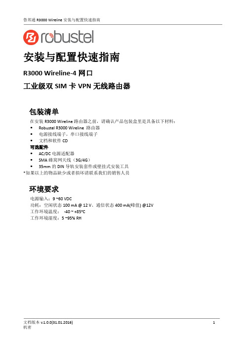
安装与配置快速指南R3000 Wireline-4网口工业级双SIM卡VPN无线路由器包装清单在安装R3000 Wireline路由器之前,请确认产品包装盒里是具备以下材料: Robustel R3000 Wireline 路由器电源接线端子,串口接线端子文档和软件CD可选配件AC/DC电源适配器SMA蜂窝网天线(3G/4G)35mm的DIN导轨安装套件或壁挂式安装工具*如果以上的物品缺少或者损坏请联系我们的销售人员环境要求电源输入:9 ~60 VDC功耗:空闲状态100 mA @ 12 V、通信状态400 mA(峰值) @12V工作环境温度:-40 ~ +85°C工作环境湿度:5 ~95% RH第1章硬件接口介绍1.1概述如图所示,R3000 Wireline路由器有四个以太网口(可配置为4xLAN或3xLAN+1xWAN),两个蜂窝网SIM卡插槽,两个蜂窝网天线接口,1xGPS和1xWi-Fi天线接口(可选)。
1.2外观尺寸外形尺寸: 43.5 x 125 x 104 mm (长x宽x高)1.3 接口PIN 脚分配1.4 LED 指示灯PIN 极性 8 正极 9 负极 10接地PIN Debug RS232 RS485 1 RXD -- 2 TXD -- 3 GND GND GND 4 -- TXD Data+(A) 5 -- RXD Data- (B)6 -- RTS 7--CTS接口引脚分配串口 (RS232或RS485)PIN 功能 1 TX+ 2 TX- 3 RX+ 6RX-1.5重置按钮1.6以太网口每个以太网口有两盏LED指示灯。
黄灯的是链路连接状态指示灯,绿灯的是数据传输速率指示灯。
第2章硬件安装2.1路由器接地路由器接地线会有助于防止电磁干扰带来的影响。
在连接设备之前,先通过接地螺丝接线让设备接地。
注意:该产品宜安装在接地良好的器件表面,如金属板。
2.2连接路由器到PC用一根标准的交叉网线连接路由器的以太网口(任一网口)到一台PC。
安东记录仪LU-R3000-6PIJ100

N:无 R:RS232 S:RS485 P:RS232 打印 E:LAN 以太网
U盘存储 N:无 U4:1G U5:2G
- III -
厦门安东电子有限公司
LU-R/C3000、LU-R/C2100 过程控制无纸记录仪使用说明书
LU-R/C3000 与 R/C2100 系列功能特点
0-5V/1-5V
输入类型
0:热电偶、热电阻、0-5V、1-5V 1:热电偶、热电阻、4-20mA、
辅 助 输 出 1类 型
0:无 J1:继电器输出(3A) J2:继电器输出(0.8A) T:固态继电器触发输出
PL/PF 控制输出
N:无 1:瞬时流量上限限值 2:瞬时流量下限限值 3:定量加注(批量控制)
- II -
厦门安东电子有限公司
LU-R/C3000、LU-R/C2100 过程控制无纸记录仪使用说明书
LU-R/C3000/2100 系列选型说明
LU-□3000-□PC□□□□□ LU-□2100-□PC□□□□□
—□PI □□□ —□PI □□□
—□PL □□ —□PL □□
—□PF □□□□ —□—□ —□PF □□□□ —□—□
PI 为位式控制通道数 (选择范围 0~16) PL 为无温压补偿流量积算通道数 (选择范围 0~8) PF 为带温压补偿流量积算通道数 (选择范围 0~8) 注:PC+PI/2+PL+PF≤8
PL/PF 流量输入类型 0:脉冲信号、0-10mA、4-20mA 1:脉冲信号、0-5V、1-5V
主控制输出类型
确认包装内容................................................................................................................................................Ⅱ
N300R说明书

3)如果上网方式为PPPOE,如下图所示,输入运营商提供给你的用户名、用
户密码、MTU值(默认值为1492如非特殊情况请勿更改)。并提供了PPPOE上网时
间控制功能,方便用户家长式的管理。
4.1.3 无线基本设置
当点击“基本设置”即可以做基本的无线通讯设置。如下图:
1、选择WEP,点击“下一步”,如下图所示:
选择密码的长度,点击“下一步”,如下图所示:
用户选择使用64字节的密码长度,输入5位的十六进制密码,选择使用128字节
的密码长度则输入13位的十六进制密码。点击“下一步”,如下图所示:
确定配置无误,点击结束,无线部分已经配置完成了。
2.2硬件安装步骤
1. 将ipTIME N300R的电源接通。
2. 将路由器的WAN口用网线连接至xDSL Modem/Cable Modem或小区提供的宽
带接口。
3. 若要进行有线连接,用双绞线将计算机与路由器的LAN口连接。
4. 若要进行无线连接,请检查您的无线网卡是否启用。若没有请启用无线网
浏览器将进入路由器设置页面,如下图所示:
点击广域网设置向导菜单进入安装向导界面,如下图所示:
用户可选择自动和手动两种网络配置,这里介绍手动网络配置。
选择手动网络配置,点击“下一步,如下图所示:
广域网连接类型:本路由器支持三种常用的上网方式,请您根据自身情况进
2、选择WPAPSK加密方式,点击“下一步,如下图所示:
选择密码系统,点击“下一步”,如下图所示:
输入8位以上的密码,点击“下一步”,如下图所示:
确定配置无误,点击结束,无线部分配置完成。
R3MIMED使用说明书

安装R3) 把r3memid.zip解压到一个空目录;
3) 运行"r3memid -nocfg -genref *"。这样产生一个用来定位坏卡上问题的好卡参考文件;
重要:请确认程序返回"no failure detected"(无失效检测到)的信息。
// 用字符串来认定
CHA02 字符串 // 指定 MDA16-23 联接到一个BANK 0 显存芯片。
// 用字符串来认定
CHA03 字符串 // 指定 MDA24-31 联接到一个BANK 0 显存芯片。
// 用字符串来认定。对1通道显卡省去。
CHC02 字符串 // 指定 MDC16-23 联接到一个BANK 0 显存芯片。
// 用字符串来认定。对1通道显卡省去。
CHC03 字符串 // 指定 MDC24-31 联接到一个BANK 0 显存芯片。
// 用字符串来认定。
CHA06 字符串 // 指定 MDA48-55 联接到一个BANK 0 显存芯片。
// 用字符串来认定。
CHA07 字符串 // 指定 MDA56-63 联接到一个BANK 0 显存芯片。
注意:如果卡上有某些芯片损坏程度使得BIOS不能检察到,显示的显存配置信息可能不同于所期望的信息。
-logext
在r3memid.log中长的额外信息。额外信息包括失效显存数据总线位完全列表,测试中探查到的总出错相数,以及当时用"-nlog"选项时很多错误显存位置和数据的。
-nlog<#>
// 文件结尾。
//
// id和掩码都是32位十六进制值。
// 单个显存配置可以指定有多个子id行,因为某些基于
R3000记录仪说明书
1 2 3 4 5 6 7 8 9 10 说明书 安装条(含 M4 螺钉) 产品合格证/保修卡 RS-232C 通讯线 RS-485 通讯线 RS-232C/485 转换模块 上位机软件(光盘) 微型打印机 优盘
名称
无纸记录仪
单位
台 本 根 份 根 根 个 张 台 个
数量
1 1 2 1
备注
可选配件 可选配件 可选配件 可选配件 可选配件 可选配件
7
第三章
技术指标
屏幕: 5.6 英寸TFT真彩色图形液晶显示屏或蓝色LCD、 320*240点阵、LED背光; 精度: 实时显示:±0.2% F.S.; 曲线显示:±0.5% F.S.; 追忆精度:±0.2% F.S.; (注:热电偶应去掉冷端误差; ) 输入规格:全隔离万能输入,1~16通道信号输入,通道 间全隔离,隔离电压大于1000V; 隔离阻抗: 20MΩ @ 1000V; 记录容量: 64/128/192/248MB(FLASH 容量可选择) ; 电压输入:0-5V、1-5V、0-20mV、0-100mV ( >1MΩ) ; 电流输入:0-10mA、4-20mA(阻抗 250Ω) ; 热电阻: PT100、Cu50(要求三线电阻平衡,引线电阻 <10Ω) ; 热电偶: S、B、K、T、E、J、F2; 其它输入信号或分度号需在订货时说明; 隔离配电输出: 变送器配电+24VDC,最多 16 路隔离配 电,配电≤30mA/路; 模拟量变送输出:4-20mA;负载能力 750Ω(最大) ; 继 电器 报 警 输出 :12 路 继电 器 触 点输 出 , 触点 容 量 3A@220VAC/1A@30VDC,可组态上上限、上限、下限、下 下限报警; 补偿方式:一般气体--温度、压力补偿测量体积流量; 过热蒸汽--温度、压力补偿,查表得到工矿密度代入 公式计算,求得质量流量; 饱和蒸汽--只进行压力补偿,查表得到工矿密度
最新R3000安装使用手册VerA

R3000 安装使用手册 VerA
精品好文档,推荐学习交流
前言
非常感谢购买本公司生产的 R3000/R4000 无纸记录仪。本安装使用手册是以初次购买者或 考虑选用者为对象,对 R3000/R4000 无纸记录仪的功能及其使用进行说明。
使用 R3000/R4000 无纸记录仪之前,请仔细阅读本手册。在充分理解的基础上,再对 R3000错误的安装或使用会导致仪表损坏 或人身伤害。
火灾。
仅供学习与交流,如有侵权请联系网站删除 谢谢II
精品好文档,推荐学习交流
开箱时若发现仪表损坏或变形,请不要使用。 仪表安装设置时注意不要让灰尘、线头、铁屑或其它东西进入,否则会发生误动作或故障。 接线必须正确,一定要进行接地。不接地可能造成触电、误动作事故、显示不正常或测量有较
大误差。 连接热电偶输入时,不要使用补偿导线以外的线材,否则会造成显示误差或动作异常。 连接热电阻输入时,要使用 3 根阻值相等且小于 10Ω的导线,否则会造成显示误差或动作异
注意
提请引起特别注意的信息
仅供学习与交流,如有侵权请联系网站删除 谢谢IV
精品好文档,推荐学习交流
DPtech DPX8000系列BRAS业务板用户手册v2.0

DPX8000系列BRAS业务板用户手册手册版本:v2.0产品版本:BRAS1000BLADE-A-S211C008D013P01声明Copyright © 2008-2016杭州迪普科技有限公司版权所有,保留一切权利。
非经本公司书面许可,任何单位和个人不得擅自摘抄、复制本书内容的部分或全部,并不得以任何形式传播。
为杭州迪普科技有限公司的商标。
对于本手册中出现的其他所有商标或注册商标,由各自的所有人拥有。
由于产品版本升级或其他原因,本手册内容有可能变更。
杭州迪普科技有限公司保留在没有任何通知或者提示的情况下对本手册的内容进行修改的权利。
本手册仅作为使用指导,杭州迪普科技有限公司尽全力在本手册中提供准确的信息,但是杭州迪普科技有限公司并不确保手册内容完全没有错误,本手册中的所有陈述、信息和建议也不构成任何明示或暗示的担保。
杭州迪普科技有限公司地址:杭州市滨江区通和路68号中财大厦6层邮编:310051网址:邮箱:support@7x24小时技术服务热线:400-6100-598约定图形界面格式约定格式意义【】带方括号“【】”表示各类界面控件名称、选项卡和数据表。
如“选择【网络管理】选项卡”。
=> 多级菜单用“=>”分隔。
如“选择【基本】=>【防火墙】=>【包过滤策略】菜单项”。
< > 带尖括号“< >”表示按钮名称,如“单击<确定>按钮”。
各类标志约定格式意义表示操作中必须注意的信息,如果忽视这类信息,可能导致数据丢失、功能失效、设备损坏或不可预知的结果。
表示对操作内容的描述进行强调和补充。
目录1产品概述................................................................................................................................................ 1-11.1概述.................................................................................................................................................... 1-11.2产品简介 ............................................................................................................................................ 1-11.3 Web管理系统介绍............................................................................................................................. 1-11.4登录WEB管理界面 ........................................................................................................................... 1-21.5常用操作介绍 ..................................................................................................................................... 1-3 2接入策略................................................................................................................................................ 2-12.1地址池配置......................................................................................................................................... 2-12.2认证服务器配置.................................................................................................................................. 2-42.3域配置................................................................................................................................................ 2-82.4免认证配置....................................................................................................................................... 2-112.5云业务配置....................................................................................................................................... 2-123 PPPoE .................................................................................................................................................. 3-13.1 PPPoE简介 ....................................................................................................................................... 3-13.2 PPPoE配置 ....................................................................................................................................... 3-13.3在线用户 ............................................................................................................................................ 3-43.4接口会话数限制.................................................................................................................................. 3-64 IPoE ...................................................................................................................................................... 4-14.1 IPoE简介........................................................................................................................................... 4-14.2 IPoE配置........................................................................................................................................... 4-24.3在线用户 ............................................................................................................................................ 4-44.4接口会话数限制.................................................................................................................................. 4-55 Portal ..................................................................................................................................................... 5-15.1 Portal简介 ......................................................................................................................................... 5-15.2 Portal配置 ......................................................................................................................................... 5-15.3在线用户 ............................................................................................................................................ 5-35.4接口会话数限制.................................................................................................................................. 5-46 802.1X ................................................................................................................................................... 6-16.1 802.1X简介 ....................................................................................................................................... 6-16.2 802.1X配置 ....................................................................................................................................... 6-16.3在线用户 ............................................................................................................................................ 6-3 Copyright © 杭州迪普科技有限公司 I7用户管理................................................................................................................................................ 7-17.1用户配置 ............................................................................................................................................ 7-18 NAT配置............................................................................................................................................... 8-18.1 NAT简介............................................................................................................................................ 8-18.2源NAT ............................................................................................................................................... 8-29 VPN配置............................................................................................................................................... 9-19.1 VPN简介 ........................................................................................................................................... 9-19.2 L2TP .................................................................................................................................................. 9-110 ALG配置 ........................................................................................................................................... 10-110.1 ALG配置........................................................................................................................................ 10-110.2 DNS ALG ....................................................................................................................................... 10-111 DDOS防护........................................................................................................................................ 11-111.1基本防护配置 ................................................................................................................................. 11-111.2 SYN Flood防护.............................................................................................................................. 11-211.3每IP新建限速防护......................................................................................................................... 11-311.4 DDoS日志配置 .............................................................................................................................. 11-4 12日志管理............................................................................................................................................ 12-112.1认证日志配置 ................................................................................................................................. 12-1 Copyright © 杭州迪普科技有限公司 II1产品概述1.1概述在当今信息化社会中,人们对网络的依赖程度越来越高。
NETGEAR N300 全功能跨界路由器 PR2000 用户安装指南说明书
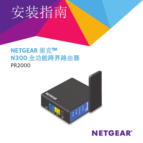
NETGEAR 崔克TM N300 全功能跨界路由器WiFi US BU S B L A NGE AR Power由此开始感谢您购买 NETGEAR N300 全功能跨界路由器 PR2000。
您可以通过把崔克设置为热点模式、扩展模式、路由模式或 3G 模式,以便使崔克连接至因特网。
注意:您也可以将崔克设置为桥接模式或接入点模式。
了解更多信息,请查看用户手册。
您可以在线访问或通过崔克用户界面的链接来获取用户手册。
了解如何访问崔克的用户界面,请查看第 19 页的查看或更改崔克的设置。
热点模式扩展模式路由模式因特网模式切换开关• Wired. 将开关切换至 Wired 以使崔克通过以太网线缆接入因特网。
例如,您需要使用崔克的路由模式或接入点模式。
• Power o . 将开关切换至 Power Off 以关闭崔克。
请确保崔克在插入电源插座前,开关位于 Power Off 状态。
• Wireless. 将开关切换至 Wireless 以使崔克通过无线接入因特网。
例如,您需要使用崔克的热点模式,扩展模式,3G 模式或桥接模式。
连接端口以及复位按键崔克具有以下端口以及复位按键:• 复位按键:用一根拉直的回形针插入复位孔按住直到因特网指示灯闪烁,即可将路由器恢复出厂设置。
• 因特网端口:工作在“Wired (有线模式)”时,作为因特网端口;工作在“Wireless (无线模式)”时,等同于局域网端口。
• 局域网端口:用于连接 1 台有线设备。
• USB 端口:用于连接 USB 移动存储设备、USB 打印机、或 3G/4G 上网卡。
当设备插在电源插座上时,此 USB 端口还可以作为一个充电器使用。
LED 指示灯通过观察路由器指示灯来了解崔克的状态:电源指示灯:• 绿色常亮:路由器已接通电源• 熄灭:路由器电源关闭因特网指示灯:• 绿色常亮:因特网已连接• 绿色闪烁:有可能是以下原因:• 按住复位按键超过 5 秒• 正在升级固件• 超过宽带限制• 熄灭:未连接至因特网无线指示灯:• 绿色常亮:无线收发功能开启• 熄灭:无线收发功能关闭USB 指示灯:• 绿色常亮:当前连接的 USB 设备可以正常工作• 熄灭:未检测到可用的 USB 设备1. 记下崔克的无线网络标识(SSID)以及无线密码。
Srun3000客户端使用手册与howto
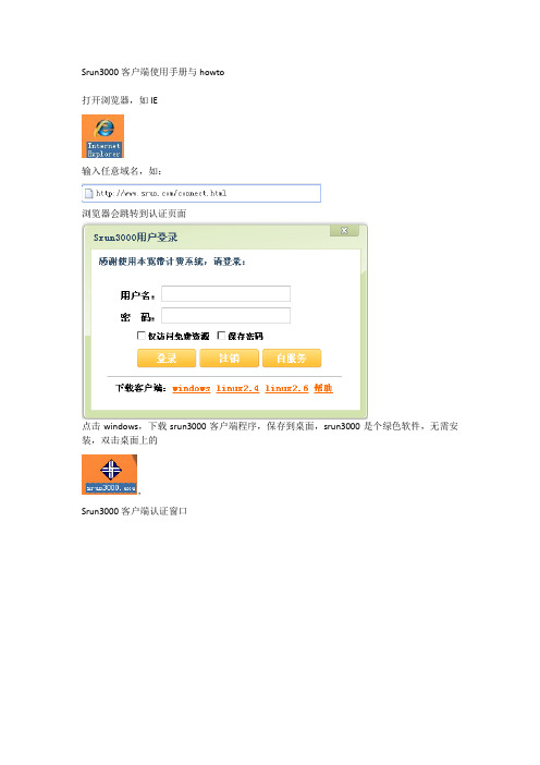
Srun3000客户端使用手册与howto打开浏览器,如IE输入任意域名,如:浏览器会跳转到认证页面点击windows,下载srun3000客户端程序,保存到桌面,srun3000是个绿色软件,无需安装,双击桌面上的,Srun3000客户端认证窗口当前任务栏里图标为蓝色的服务器地址通常无需手工输入,输入用户名密码勾上仅访问免费资源:通常情况,是无需勾上的,该功能是针对区分国内国际流量的计费策略,勾上后只能访问后台定义的免费IP列表(通常是国内IP),访问这部分资源产生的明细记录在免费流量里。
勾上保存密码,下次登录则无需重新输入密码。
服务器地址如无法获取,在认证服务器一栏里手工输入,IE跳转的页面的仅IP部分,如:提示用户名错误:请检查用户名是否正确,如正确,则可能数据库与认证系统未同步,1分钟后再试。
提示密码错误或登录超时:用户密码不正确,请检查密码,或者网络设置有问题,检查网络设置。
提示IP已存在:通常发生在同一台机器,不同账号使用的时候,上一个用户数据与认证服务还未同步(同步时间小于1分钟),请1分钟后在认证。
提示用户已禁用:用户被管理员手工查封,请联系管理员了解原因。
提示用户已欠费:请续费后,再开通。
提示用户时间到期,当用户计费策略为包月计费、包月限制流量计费、包月限制流量计费模式,在结算日期前3天会有提醒功能。
提示用户流量不足,当用户计费策略为流量计费或包月限制流量计费模式,在当月可用流量小于10M会有提醒功能。
提示用户流量时间,当用户计费策略为时间计费或包月限制流量计费模式,在当月可用时间小于1个小时会有提醒功能。
认证通过后,点击查看:可以查看用户本次上网更为详细的信息如用户计费方式为包月、包月限制时间、包月限制流量,状态里的结算日期会显示下一个结算日期,如是时间计费或包月限制时间计费模式,则可用时长里会显示余额换算成时间后,剩余多少可用时间。
如是流量计费或包月限制流量计费模式,则可用时长里会显示余额换算成流量后剩余多少可用流量。
鲁邦通 GoRugged R3000 Wireline-2 以太网口 工业级 VPN 路由器 用户手
鲁邦通GoRugged R3000 Wireline-2以太网口工业级VPN路由器用户手册关于文件该文件描述双SIM卡工业2G/3G/4G路由器——鲁邦通R3000 Wireline的软硬件功能。
版权所有©广州鲁邦通物联网科技有限公司保留一切权利商标许可Robustel是广州鲁邦通物联网科技有限公司的商标。
该文件中提及的其他商标和商业名称均属于各自持有者。
免责声明未经版权拥有者允许,不得以任何形式复制该文件的任意部分。
由于方法、设计、生产工艺的不断改进,文件内容可能在未预先通知的情况下进行修订。
因使用该文档导致任何错误或损坏,鲁邦通概不负责。
技术支持联系方式电话:+86-020-********传真:+86-020-********邮件:********************网址:重要注意/通知由于无线通信的特性,数据不能确保百分之百地传输和接收。
数据可能延迟、损坏(即有错误)或全部丢失。
虽然在一个状况良好的网络里正常使用路由器这样的无线设备传输或接收数据时,数据很少会有明显地丢失或延迟,但是在数据传输或接收失败会对用户或其他人造成人身伤害、死亡或财产损失的情况下,建议不要使用无线路由器。
由于传输或接收数据过程中的数据延迟、错误或数据传输接收失败而导致的严重后果,鲁邦通概不负责。
安全防范常规●该路由器会产生射频。
使用该路由时必须注意射频干扰和射频设备规定的安全问题。
●不要在飞机、医院、加油站或其他禁止使用无线通信产品的地方使用路由器。
●要确保附近的设备不会干扰路由器。
比如:心脏起搏器、医疗设备。
路由器天线应该远离计算机、办公设备、家用电器等。
●路由器必须正确连接外部天线。
在路由器上只能使用经过验证的标准天线。
想要寻求符合标准的天线,请联系授权经销商。
●天线与人体至少保持20cm以上的安全距离。
不要把天线放在金属盒子、集装箱等金属容纳物中。
●射频辐射暴露声明1.对于没有协同定位的移动设备(安装发射天线的地方要远离人体至少20cm。
地毯清洁器 R3 操作手册说明书

R*9003730*9003730Rev.01(09-2018)型号:9004199-230V有关最新部件手册及其他语言的操作手册,请访问:/manualsChinaCN 操作T ennant R3(09-2018)2本手册随每种新型号提供。
提供必要的操作和维护说明。
在操作或维修机器前,请详读本手册并熟悉机器。
本机器将提供出众的服务。
但是,只有在以下情况下才能以最低成本获得最好的结果:S 机器操作时得到合理的照顾。
S 定期维护机器-按照提供的机器维护说明。
S 使用制造商提供的或同等部件维护机器。
要查看、打印或下载手册,请在线访问/manuals打开机器包装:仔细检查硬纸箱是否存在损坏迹象。
立刻向运营商报告损坏。
保护环境请按照当地废物处理法规以环境安全的方式处理包装材料和旧的机器组件。
始终记住再循环。
Tennant Company PO Box 1452Minneapolis,MN 55440USA Phone:(800)坦能清洁系统设备(上海)有限公司上海市青浦区工业园区天盈路66号3号楼,201700电话:(86-21)6922-5333传真:(86-21)规格和零件可能更改,恕不另行通知。
版权所有©2008-2018TENNANT Company.保留所有权利。
中国印刷机器数据目录安全预防措施3...............................接地说明3...............................安全标签4...................................机器组件5...................................机器应用6...................................机器设置6...................................安装滚轮6...............................加注清水箱6.............................连接电源线7.............................机器操作7...................................操作前7.................................清洁地毯8...............................使用附带工具清洁(选配件)9.............机器维护10...................................每次使用后10.............................每使用10小时后11.......................每使用100小时后11......................刷马达维护11.............................存放机器11...................................推荐存放物品12...............................故障排除12...................................机器规格13...................................机器尺寸13...................................操作CN3T ennant R3(03-08)安全预防措施本机器用于商业用途。
Ericsson MASTR III 基站系统维护手册说明书
LBI-38775FMaintenance ManualMASTR® IIIBASE STA TIONTABLE OF CONTENTST/R SHELF . . . . . . . . . . . . . . . . . . . . . . . . . . LBI-38637SYSTEM MODULE . . . . . . . . . . . . . . . . . . . . . LBI-38764POWER MODULE . . . . . . . . . . . . . . . . . . . . . . LBI-38752Ericsson Inc.Private Radio SystemsMountain View RoadLynchburg, Virginia 24502ericssonz1-800-528-7711 (Outside USA, 804-528-7711)Printed in U.S.A.Copyright© February 1992, Ericsson GE Mobile Communications Inc.INTRODUCTIONThis manual contains information for the MASTR III Station including application information, cable diagrams and a parts list for the cabinet hardware. For additional information refer to the following manuals:LBI-38636Installation How to install including Interconnection Diagrams.LBI-39074InstallationInstallation, Configuration and Checkout for EDACS Basic or Level 1 System.LBI-38754VHF RF Package Information on the VHF frequency equipment.LBI-38675UHF RF Package Information on the UHF frequency equipment.LBI-39025800 MHz RF Package Information on the 800 MHz frequency equipment.LBI-38983Antenna SystemsInformation on typical antenna system installations.LBI-38812EDACS Interface Panels Information on the panel used in EDACS applications.LBI-38894GETCInformation on the GETC equipment.LBI-38625Charger/Emer. PowerInformation on the battery charger and emergency power equipment.APPLICATIONSOPTION NUMBER APPLICATION ASSEMBLY DESCRIPTIONSXCAIS 19D902845P1Installation of one MASTR III station in a 37" indoor cabinet.SXRB1J 19D902845P2Installation of T/R shelf for MASTR III station.SXSU3A 19D902845P3Installation of coax switch.SXDU1J SXDU1K SXDU1M 19D902845P4Installation of VHF (150-162 MHz) duplexer.Installation of VHF (162-174 MHz) duplexer.Installation of UHF (450-470 MHz) duplexer.SXCH1L/M 19D901845P5Installation of battery charger with automobile battery emergency power in a 37" indoor cabinet.SXCH1R SXCH3A 19D902845P6Installation of battery charger with Gel Cell battery emergency power in a 37" in-door cabinet.SXSU3D 19D902845P7Installation of SOR Relay Kit.SXMK3C 19D902845P8Installation of MASTR II auxiliary receiver in a 37" or 69" cabinet.19D902845P8Installation of MASTR III auxiliary receiver in a 37" or 69" cabinet.SXMD3J 19D902845P9Installation of GETC shelf in a 69" indoor cabinet.SXVG3E SXVG3F 19D902845P11Installation of GETC shelf for a E/E V oice Guard/Aegis repeater and remote/repeater in a 37" or 69" indoor cabinet.SXVV1N SXVW1J SXVV1M 19D902845P12Installation of E/D module (non-1027 version) in a 37" or 69" indoor cabinet.SXVG3C SXVG3D 19D902845P13Installation of E/D module (1027 version) in a 37" or 69" indoor cabinet.SXDE5B 19D902845P14Installation of transmit data board.SXAP3K 19D902845P16Installation of multi-station in a 69" or 83" indoor cabinet or open rail rack.SXMNEY SXMD3M 19D902845P2119D902845P22Installation in 69" indoor cabinet or open rail rack.Installation of simulcast stations.SXMD1S 19D902845P23Installation and modification instructions for RIC telephone interconnect.SXVT1B 19D902845P24Modification for station receiver voting for RS-232.19D902845P25Installation in 45" weatherproof cabinet.SXVT1L 19D902845P26Modem V oting installation.SXCP5T19D902845P27CNI installation.This manual is published by Ericsson Inc., without any warranty. Improvements and changes to this manual necessitated by typographical errors,inaccuracies of current information, or improvements to programs and/or equipment, may be made by Ericsson Inc., at any time and without notice. Such changes will be incorporated into new editions of this manual. No part of this manual may be reproduced or transmitted in any form or by any means, electronic or mechanical, including photocopying and recording, for any purpose, without the express written permission of Ericsson Inc.LBI-38775F1LBI-38775FASSEMBL Y DIAGRAMMASTR III STATION19D902845P1(19D902845, Sh. 1, Rev. 5)2LBI-38775F ASSEMBL Y DIAGRAM ArrayMASTR III STATION(19D902845, Sh. 2, Rev. 2)3ASSEMBL Y DIAGRAMMASTR III STATION (19D902845, Sh. 3, Rev. 4)MASTR III STATION (19D902845, Sh. 3A, Rev. 3)LBI-38775F 4ASSEMBL Y DIAGRAM MASTR III STATION(19D902845, Sh. 5, Rev. 3)MASTR III STATION(19D902845, Sh. 4, Rev. 1)LBI-38775F5LBI-38775FASSEMBL Y DIAGRAMMASTR III STATION19D902845P2, P7 & P14(19D902845, Sh. 6, Rev. 8)6LBI-38775F ASSEMBL Y DIAGRAMMASTR III STATION(19D902845, Sh. 7, Rev. 4)7ASSEMBL Y DIAGRAMMASTR III STATION19D902845P3(19D902845, Sh. 8, Rev. 5)MASTR III STATION19D902854P4(19D902845, Sh. 9, Rev. 3)LBI-38775F8LBI-38775F ASSEMBL Y DIAGRAMMASTR III STATION19D902845P5(19D902845, Sh. 10, Rev. 2)9LBI-38775FASSEMBL Y DIAGRAMMASTR III STATION19D902845P6(19D902845, Sh. 11, Rev. 1)LBI-38775F ASSEMBL Y DIAGRAMMASTR III STATION(19D902845, Sh. 12, Rev. 1)LBI-38775FASSEMBL Y DIAGRAMMASTR III STATION19D902845P21(19D902845, Sh. 13, Rev. 2)LBI-38775F ASSEMBL Y DIAGRAMMASTR III STATION(19D902845, Sh. 14, Rev. 3)LBI-38775FASSEMBL Y DIAGRAMMASTR III STATION(19D902845, Sh. 15, Rev. 3)LBI-38775F ASSEMBL Y DIAGRAMMASTR III STATION19D902845, Sh. 15A, Rev. 3)ASSEMBL Y DIAGRAMMASTR III STATION(19D902845, Sh. 16, Rev. 2)LBI-38775FASSEMBL Y DIAGRAMMASTR III STATION(19D902845, Sh. 17, Rev. 1)MASTR III STATION WITH MASTR II AUXILIARY RECEIVER19D902845P8(19D902845, Sh. 18, Rev. 3)LBI-38775FLBI-38775FASSEMBL Y DIAGRAMMASTR III STATION19D902845P9(19D902845, Sh. 19, Rev. 7)LBI-38775F ASSEMBL Y DIAGRAMMASTR III STATION19D902845P11 - P13(19D902845, Sh. 20, Rev. 6)LBI-38775FASSEMBL Y DIAGRAMMASTR III STATION(19D902845, Sh. 21, Rev. 3)LBI-38775F ASSEMBL Y DIAGRAMMASTR III STATION19D902845P15(19D902845, Sh. 22, Rev. 8)LBI-38775FASSEMBL Y DIAGRAMMASTR III STATION19D902845P16(19D902845, Sh. 23, Rev. 9)LBI-38775F ASSEMBL Y DIAGRAMMASTR III STATION19D902845P16(19D902845, Sh. 23A, Rev. 5)LBI-38775FASSEMBL Y DIAGRAMMASTR III STATION19D902845P16(19D902845, Sh. 24, Rev. 7)LBI-38775F ASSEMBL Y DIAGRAMMASTR III STATION(19D902845, Sh. 25, Rev. 6)ASSEMBL Y DIAGRAMMASTR III STATION 19D902845P23(19D902845, Sh. 26, Rev. 5)LBI-38775FASSEMBL Y DIAGRAM MASTR III STATION19D902845P24(19D902845, Sh. 27, Rev. 3)LBI-38775FASSEMBL Y DIAGRAMMASTR III STATION 19D902845P22(19D902845, Sh. 28, Rev. 4)LBI-38775FLBI-38775F ASSEMBL Y DIAGRAMMASTR III STATION19D902845P25(19D902845, Sh. 29, Rev. 2)LBI-38775FASSEMBL Y DIAGRAMMASTR III STATION19D902845P26 & P27(19D902845, Sh. 30, Rev. 5)LBI-38775F ASSEMBL Y DIAGRAMMASTR III STATION WITHMASTR III MULTIPLE RECEIVER19D902845P8(19D902845, Sh. 18A, Rev. 2)ASSEMBL Y DIAGRAM HARNESS19C337792P1(19C337792, Sh. 1, Rev.2), ( 19B803755, Sh.1, Rev. 3)LBI-38775FCABLE DIAGRAMS19B801454P16 & P47(19B801454, Sh. 10, Rev. 25)19B801454P17 & P18(19B801454, Sh. 11, Rev. 13)19B801454P19 & P20(19B801454, Sh. 12, Rev. 9)19B801454P24 (19D801454, Sh. 15, Rev. 25)19B801454P43 (19B801454, Sh. 23, Rev. 20) LBI-38775FCABLE DIAGRAMS CONTROL CABLE ASSEMBLY (part of Power Amplifier) - 19B801739P1(19B801739, Sh. 1, Rev. 2)POWER CABLE (part of Power Amplifier) - 19B801937P1 (19B80937, Sh. 1, Rev. 1)19B235871P1 (19B235871, Sh. 1, Rev. 2)344A3052P1 (344A3052, Sh. 1, Rev. 1)LBI-38775FPARTS LIST *COMPONENTS, ADDED, DELETED OR CHANGED BY PRODUCTION CHANGESSYMBOL PART NO.DESCRIPTION- - - - - - - 37" CABINET - - - - - -19D902838P137-inch Cabinet.19C852074P1Equipment support rail (left side).19C852074P2Equipment support rail (right side).344A3450G1Hardware Kit.344A3450G2Hardware Kit.19D902422P4Rear Door.19D902422P4Front Door.19J706152P5Tie Strap.5491682P4Key, sim to Y ale & T owne #BF-10A 5490407P29Grommet.- - - - - - - - 69" CABINET - - - - - - -19D417358G369-inch Cabinet.19D417623G4Grill, Label.19A130031G12Hardware Kit.19B226318P2Plate.19B801476P1Cover.19B801476P2Cover.19B209539P1Lock, rim.19B209539P2Lock, rim.19B209539P3Key, lock, rim.344A3450G21Hardware Kit.5490407P29Grommet.- - - - - - 83" CABINET - - - - - - -19D902663G183-inch Cabinet.19C337428G1Door.19C337428G2Door.19B801476P1Cover.19B801476P2Cover.19B209539P2Lock, rim.19B209239P2Lock, rim.19B209539P3Key, lock, rim.19B226318P2Plate.344A2450P21Hardware Kit.- - - - - - CABLES - - - - - - -19B235871P1Power Cable: Station Power Supply (J801) to T/R Shelf (A2-P102).19B801454P17RF Cable: Low Pass Filter (J1) to Power Amplifier (J104). Replaced by 19B801454P43.19B801454P20RF Cable: T/R Shelf (J2) to Duplexer Shelf (J2)(Used when Duplexer is installed).19B801454P19RF Cable: T/R Shelf (J2) to Antenna Switch (J2).19B801454P16RF Cable: T/R Shelf (J1) to Power Amplifier (J101).19B801454P43RF Cable: Low Pass Filter (J1) to PowerAmplifier (J104).MASTR III STATIONISSUE 3LBI-38775F。
联想R3000无线路由器设置方法介绍

联想R3000无线路由器设置方法介绍本文主要是关于联想R3000无线路由器的相关介绍,并着重对联想R3000无线路由器的设置方法进行了详尽的阐述。
无线路由器无线路由器是用于用户上网、带有无线覆盖功能的路由器。
无线路由器可以看作一个转发器,将家中墙上接出的宽带网络信号通过天线转发给附近的无线网络设备(笔记本电脑、支持wifi的手机、平板以及所有带有WIFI功能的设备)。
市场上流行的无线路由器一般都支持专线xdsl/ cable、动态xdsl、pptp四种接入方式,它还具有其它一些网络管理的功能,如dhcp服务、nat防火墙、mac地址过滤、动态域名等功能。
[1]市场上流行的无线路由器一般只能支持15-20个以内的设备同时在线使用。
一般的无线路由器信号范围为半径50米,现在已经有部分无线路由器的信号范围达到了半径300米。
无线路由器(Wireless Router)好比将单纯性无线AP和宽带路由器合二为一的扩展型产品,它不仅具备单纯性无线AP所有功能如支持DHCP客户端、支持VPN、防火墙、支持WEP 加密等等,而且还包括了网络地址转换(NAT)功能,可支持局域网用户的网络连接共享。
可实现家庭无线网络中的Internet连接共享,实现ADSL、Cable modem和小区宽带的无线共享接入。
无线路由器可以与所有以太网接的ADSL MODEM或CABLE MODEM直接相连,也可以在使用时通过交换机/集线器、宽带路由器等局域网方式再接入。
其内置有简单的虚拟拨号软件,可以存储用户名和密码拨号上网,可以实现为拨号接入Internet的ADSL、CM等提供自动拨号功能,而无需手动拨号或占用一台电脑做服务器使用。
此外,无线路由器一般还具备相对更完善的安全防护功能。
3G路由器主要在原路由器嵌入无线3G模块。
首先用户使用一张资费卡(USIM卡)插3G 路由器,通过运营商3G网络WCDMA、TD-SCDMA等进行拨号连网,就可以实现数据传输、上网等。
R3000型说明南京依特佳电子安防系统,02584586720

eGuardEASR3000型射频检测器使用说明南京依特佳电子安防系统有限公司2006年6月R3000型接收机技术说明R3000型主板为数码芯片及单片机进行工作。
设备为免调试型。
操作简单,抗干扰能力远远优于模拟线路主板。
1、使用DS1、DS2、DS3三个绿色发光二极管来反映环境干扰情况;在现场,当DS1闪烁,DS2、DS3不亮时,表示环境有一定干扰,设备可正常使用,但检测率最高可下降30%;若DS1一直亮,则不管DS2、DS3为何种状态,皆表明安装地点干扰严重,需确定干扰源并排除,或采取改变安装方案、地点等方式解决。
2、顺时针调整VR4,可提高检测灵敏度,此时DS1、DS2、DS3绿色发光二极管可能会闪烁;静态调整时,以满足现场标签检测灵敏度,且DS1、DS2、DS3绿色发光二极管均不闪烁(亮)为最佳状态。
3、调制频率自适应发射板调制频率改变时(错频)R 3000型接收机不需要调整。
4、声、光报警设置JP2设置为1&2时(出厂状态),声光报警同步发生,持续2秒。
JP2设置为2&3时,声、光报警同步发生,持续2秒,随后声音停止,报警灯仍持续闪亮3秒。
5、安装距离与标签配置安装距离1米至1.2米,软硬标签可同时使用;JP1设置1&2连接。
安装距离大于1.2米小于1.6米时,建议只使用硬标签;JP1设置2&36、主要参数:输入直流电压…………………………………24±VDC警戒状态…………………………………250mA报警状态…………………………………<300 mA保险………………………………………250V,1A(延迟式)检测标签速度……………………………大于2米/秒7、主要测试点A、TP1点—射频(RF)接收幅度安装距离<1.2米时,JP1设置1&2连接(自动状态),TP1点射频接收幅度为500±50mVp—p。
安装距离>1.2、<1.6米时,JP1设置2&3连接(手动状态),TP1点射频接收幅度为300±50 mVp—p;可通过调节VR2满足安装要求。
千寻位置 XD-R3005G GD 车载高精度定位器 使用说明书

车载高精度定位器XD-R3005G/GD 使用说明书版本R1.1感谢您选用XD-R3005G/GD型车载高精度定位器。
使用本产品之前请务必认真阅读本说明。
XD-R3005GD型多频段车载高精度定位终端采用了4G全网通通信,以及高灵敏度天线,结合地基增强差分系统,可以实现厘米级精度的动态定位。
4G全网通可同时兼容中国移动/中国联通/中国电信的LTE网络,在4G 信号不佳的情况下可兼容中国移动/中国联通的3G/2G网络。
本设备配置RTK动态测量技术,使用RTK动态测量结合地基增强网络对卫星信号进行差分解析,获得最高厘米级精度,有高可靠性。
重要注意事项本产品为电子产品,需带电工作,若电源或电源线出现故障或损坏,为了相关使用人员人身安全,请停止使用并联系技术人员。
本产品若遭受设计防护等级外的损坏导致外壳破损电路暴露,或因故浸泡液体后,请立即停止使用并联系技术人员。
请保证本产品的安装工作由经受专业培训的人员进行,并能够在合适的电源(DC 12~36V)供应下工作。
注意未经专业人员许可或指导,请勿擅自拆解产品擅自拆解产品会有触电风险https:///market千寻位置时空智能市场性能参数尺寸178mm×119mm×42mm重量670g通信制式LTE/WCDMA/TD-SCDMA/GSM/ 蓝牙4.0位置精度单点定位 1.0m DGPS0.5mRTK0.02m+1ppm卫星定位频率BDS B1l /B2l GPS L1C / A /L2C GLONASS G1OF /G2OF定位灵敏度-160dBm数据更新率最高支持1Hz 热启动≤1s冷启动≤32s重捕获≤1s速度精度GDS+GPS双模0.05m/s BDS0.05m/s最大速度500m/s电源输入电压下限12V 电压上限36V设备功耗<2.5W温度要求工作温度-20℃~70℃储存温度-30℃~80℃湿度要求5%~95%(无凝结)接口指标SMA×2 TNC-KY×1 GX16-2×1 GX16-3×1https:///market 千寻位置时空智能市场产品清单多频大天线和BNC 接口延长线根据天线需求会特别配备BNC/SMA 转接头XD-R3005G主机×1SMA 接口4G 天线/延长天线×1SMA 接口蓝牙天线×1GX16-2电源转接线×1GX16-3转RS232串口转接线×1https:///market千寻位置时空智能市场安装步骤插入SIM卡卸除设备底部四颗螺丝,小心取出底盘。
- 1、下载文档前请自行甄别文档内容的完整性,平台不提供额外的编辑、内容补充、找答案等附加服务。
- 2、"仅部分预览"的文档,不可在线预览部分如存在完整性等问题,可反馈申请退款(可完整预览的文档不适用该条件!)。
- 3、如文档侵犯您的权益,请联系客服反馈,我们会尽快为您处理(人工客服工作时间:9:00-18:30)。
声
明
z 本手册版权属于浙江中控自动化仪表有限公司,事先未经明确的书面许可不得复制或修改本手 册内容。
z 本手册中如有难于理解的地方或有错误、遗漏等问题,敬请联系我们的技术支持,欢迎拨打客 户中心免费电话:800-88571248。
-I-
MultiF R3000/R4000 无纸记录仪
使用之前,请仔细阅读安全注意事项,以便正确使用。
险。 z 接通电源后,请不要触摸端子,否则会有触电危险或产生误动作。 z 关闭电源后,才可进行部件单元的拆卸,否则会有触电危险或产生误动作。 z R3000/R4000 无纸记录仪壳体两侧的通风孔需保持通畅,以免发生故障、动作异常、寿命
降低和火灾。
- II -
MultiF 0/R4000 无纸记录仪
作异常。 z 定期检查端子螺钉和安装螺钉,请不要在松动的情况下使用。 z 仪表运行期间,端子盖必须安装在端子板上。 z 仪表在运行中,进行修改组态、信号输出、启动、停止等操作之前,应充分地考虑安全
性,错误的操作会使工作设备损坏或发生故障。 z 请使用干布擦拭仪表,不要使用酒精、汽油或其它有机溶剂,不要把水溅到仪表上,如
3.1 外包装检查.................................................................................................................................................11 3.2 开箱.............................................................................................................................................................11 3.3 装箱物品清单.............................................................................................................................................11
1.2.1 功能原理 .............................................................................................................................................. 3 1.2.2 技术参数 .............................................................................................................................................. 3 1.3 投运步骤...................................................................................................................................................... 7 1.3.1 开箱 .................................................................................................................................................... 8 1.3.2 安装 .................................................................................................................................................... 8 1.3.3 接线 .................................................................................................................................................... 8 1.3.4 接通电源 ............................................................................................................................................ 8 1.3.5 进行组态 ............................................................................................................................................ 8 1.3.6 投运 .................................................................................................................................................... 9 1.3.7 切断电源 ............................................................................................................................................ 9
4.1 使用环境.................................................................................................................................................... 12 4.2 安装尺寸.................................................................................................................................................... 12 4.3 安装步骤.................................................................................................................................................... 13 4.4 接线............................................................................................................................................................ 13
z 安全注意事项记载了有关安全的重要内容,请务必遵守。安全事项分为“危险”和“注意”两 类。表示和含义如下:
危 险 表示若不采取适当的预防措施的话,将造成严重的人身伤 害、伤亡或重大的财产损失。
注 意 提醒您对产品有关的重要信息、产品的处置或文件的特别部 分格外注意!
危险
z 本仪表可以正常工作于一般场合,如果担心本仪表的故障或异常会造成重大事故或损坏其 它设备时,应另外设置避免事故的紧急停止电路和保护回路,以防止事故的发生。
第二章 记录仪型号规格代码............................................................................................................................. 10
第三章 开 箱 .....................................................................................................................................................11
z 为避免发生仪表故障,请提供额定电压范围内的电源。 z 为了防止触电或者产生误动作和故障,在安装和接线结束之前,请不要接通电源。 z R3000/R4000 无纸记录仪是非本安防爆产品,请不要在有可燃或爆炸性气体的环境中使用。 z 绝对不要擅自拆卸、加工、改造或修理本仪表,否则会有产生异常动作、触电或火灾的危
在仪表到货之日起的 1 年质保期内收到用户有关这类缺陷的通知,本公司将对确实有缺陷的产 品实行免费修理或更换。本公司的所有产品均承诺终身维修。
浙大中控®、SUPCON®和 MultiF®是浙江中控自动化仪表有限公司的注册商标。
浙江中控自动化仪表有限公司 2004 年 12 月
第四章 安装与接线............................................................................................................................................. 12
注意
提请引起特别注意的信息
- IV -
MultiF R3000/R4000 无纸记录仪
目录
第一章 概 述 ...................................................................................................................................................... 1
