CTCH108F-821K中文资料
BSH108,215;中文规格书,Datasheet资料

BSH108N-channel enhancement mode field-effect transistorRev. 02 — 25 October 2000Product specification1.DescriptionN-channel enhancement mode field-effect transistor in a plastic package using TrenchMOS™1 technology.Product availability:BSH108 in SOT23.2.Featuress TrenchMOS™ technology s Very fast switching s Logic level compatiblesSubminiature surface mount package.3.Applicationss Battery management s High speed switchs Low power DC to DC converter.4.Pinning information1.TrenchMOS is a trademark of Royal Philips Electronics.Table 1:Pinning - SOT23, simplified outline and symbolPin Description Simplified outlineSymbol1gate (g)SOT232source (s)3drain (d)MSB003Top view123sdgMBB0765.Quick reference dataTable 2:Quick reference dataSymbol Parameter Conditions Typ Max Unit V DS drain-source voltage (DC)T j=25to150°C−30VI D drain current (DC)T sp=25°C; V GS=5V− 1.9AP tot total power dissipation T sp=25°C−0.83W T j junction temperature−150°C R DSon drain-source on-state resistance V GS=10V; I D=1A77120mΩV GS=5V; I D=1A102140mΩ6.Limiting valuesTable 3:Limiting valuesIn accordance with the Absolute Maximum Rating System (IEC 60134).Symbol Parameter Conditions Min Max Unit V DS drain-source voltage (DC)T j=25to150°C−30VV DGR drain-gate voltage (DC)T j=25to150°C; R GS=20kΩ−30VV GS gate-source voltage (DC)−±20VI D drain current (DC)T sp=25°C; V GS=5V;Figure2and3− 1.9AT sp=100°C; V GS=5V;Figure2− 1.2AI DM peak drain current T sp=25°C; pulsed; t p≤10µs;Figure3−7.5AP tot total power dissipation T sp=25°C;Figure1−0.83W T stg storage temperature−65+150°C T j operating junction temperature−65+150°C Source-drain diodeI S source (diode forward) current (DC)T sp=25°C−0.83AI SM peak source (diode forward) current T sp=25°C; pulsed; t p≤10µs− 3.3AV GS ≥5VFig 1.Normalized total power dissipation as afunction of solder point temperature.Fig 2.Normalized continuous drain current as afunction of solder point temperature.T sp =25°C; I DM is single pulse.Fig 3.Safe operating area; continuous and peak drain currents as a function of drain-source voltage.03aa170204060801001200255075100125150175P der T sp(o C)(%)03aa25204060801001200255075100125150175I der T sp (o C)(%)P der P totP tot 25C °()----------------------100%×=I der I DI D 25C °()------------------100%×=03aa8010-310-210-111010-1110102V DS (V)I D (A) D.C.100ms10msR DSon =V DS /I D1mst p =10µs 100µs T sp =25o Ct pt p TPtTδ =7.Thermal characteristics7.1Transient thermal impedanceTable 4:Thermal characteristicsSymbol ParameterConditionsValue Unit R th(j-sp)thermal resistance from junction to solder point mounted on a metal clad substrate;Figure 4150K/W R th(j-a)thermal resistance from junction to ambientmounted on a printed circuit board;minimum footprint350K/WMounted on a metal clad substrate.Fig 4.Transient thermal impedance from junction to solder point as a function of pulse duration.03aa7910-111010210310-510-410-310-210-1110t p (s)Z th(j-sp)(K/W)single pulseδ=0.50.20.10.050.02t pt p TPtTδ =8.CharacteristicsTable 5:CharacteristicsT j=25°C unless otherwise specifiedSymbol Parameter Conditions Min Typ Max Unit Static characteristicsV(BR)DSS drain-source breakdown voltage I D=10µA; V GS=0VT j=25°C3040−VT j=−55°C27−−VV GS(th)gate-source threshold voltage I D=1mA; V DS=V GS;Figure9T j=25°C1 1.52VT j=150°C0.5−−VT j=−55°C−− 3.2VI DSS drain-source leakage current V DS=24V; V GS=0VT j=25°C−0.01 1.0µAT j=150°C−−10µA I GSS gate-source leakage current V GS=±10V; V DS=0V−10100nA R DSon drain-source on-state resistance V GS=10V; I D=1A;Figure7and8T j=25°C−77120mΩV GS=5V; I D=1A;Figure7and8T j=25°C−102140mΩT j=150°C−170240mΩDynamic characteristicsg fs forward transconductance V DS=10V; I D=1A;Figure112 4.5−SQ g(tot)total gate charge V DD=15V; V GS=10V; I D=5A;Figure14− 6.410nC Q gs gate-source charge−0.5−nC Q gd gate-drain (Miller) charge− 1.3−nC C iss input capacitance V GS=0V; V DS=10V; f=1MHz;Figure12−190−pF C oss output capacitance−70−pF C rss reverse transfer capacitance−50−pF t d(on)turn-on delay time V DD=10V; R L=10Ω; V GS=10V; R G=6Ω−3−ns t r rise time−8−ns t d(off)turn-off delay time−15−ns t f fall time−26−ns Source-drain diodeV SD source-drain (diode forward) voltage I S=0.83A; V GS=0V;Figure13−0.8 1.2Vt rr reverse recovery time I S=1A; dI S/dt=−100A/µs; V GS=0V;V DS=25V −25−nsQ r recovered charge−20−nCT j =25°C T j =25°C and 150°C; V DS >I D ×R DSonFig 5.Output characteristics: drain current as afunction of drain-source voltage;typical values.Fig 6.Transfer characteristics: drain current as afunction of gate-source voltage; typical values.T j =25°CFig 7.Drain-source on-state resistance as a functionof drain current; typical values.Fig 8.Normalized drain-source on-state resistancefactor as a function of junction temperature.03aa8100.511.522.533.544.5500.20.40.60.811.2 1.4 1.6 1.82V DS (V)I D(A) 3 V2 V2.2 V 2.4 V 2.6 VV GS = 2.8 V3.4 V T j = 25 o C5 V10 V 03aa8300.511.522.533.544.5500.511.522.533.54V GS (V)I D (A)V DS > I D X R DSonT j = 25 o C150 o C03aa8200.050.10.150.20.250.30.350.40.450.50.511.522.533.544.55I D (A)R DSon(Ω)V GS = 10 V T j = 25 o C 3 V5 V2.2 V2.4 V2.6 V2.8 V3.4 V03aa2700.20.40.60.81.01.21.41.61.82.0-60-202060100140180T j(o C)aa R DSonR DSon 25C °()---------------------------=I D =1mA; V DS =V GS T j =25°C; V DS =5VFig 9.Gate-source threshold voltage as a function ofjunction temperature.Fig 10.Sub-threshold drain current as a function ofgate-source voltage.T j =25°C and 150°C; V DS >I D ×R DSon V GS =0V; f =1MHzFig 11.Forward transconductance as a function ofdrain current; typical values.Fig 12.Input,output and reverse transfer capacitancesas a function of drain-source voltage; typical values.03aa3300.511.522.5-60-202060100140180maxtypminV GS(th)T j (o C)(V)03aa360.511.522.53maxtyp minI DV GS (V)10-610-510-410-310-210-1(A)03aa8401234567800.511.522.533.544.55I D (A)g fs (S)V DS > I D X R DSonT j = 25 o C150 o C03aa861010210310-1110102V DS (V)C iss , C oss , C rss (pF)C issC ossC rssT j =25°C and 150°C; V GS =0V I D =0.5A; V DD =15V; T j =25°CFig 13.Source (diode forward) current as a function ofsource-drain (diode forward) voltage; typical values.Fig 14.Gate-source voltage as a function of gatecharge; typical values.03aa8500.511.522.533.544.5500.20.40.60.811.2 1.4V SD (V)I S (A)150 o CT j = 25 o CV GS = 0V03ab100123456789101112131415012345678910Q G (nC)V GS (V)I D = 0.5 A T j = 25 o CV DD = 15 V9.Package outlineFig 15.SOT23.UNIT A 1max.b p c D E e 1H E L p Q w v REFERENCESOUTLINE VERSION EUROPEAN PROJECTIONISSUE DATE 97-02-2899-09-13IECJEDEC EIAJmm0.10.480.380.150.093.02.81.41.20.95e 1.92.52.10.550.450.10.2DIMENSIONS (mm are the original dimensions)0.450.15SOT23TO-236ABb pD e 1eAA 1L pQdetail XH EE w M v M ABAB 01 2 mmscaleA 1.10.9cX123Plastic surface mounted package; 3 leadsSOT2310.Revision historyTable 6:Revision historyRev Date CPCN Description022*******-Product specification; second version; supersedes Rev.01 of 20000906.Correction to diode I S; see Table 3 “Limiting values”0120000906-Product specification.分销商库存信息: NXPBSH108,215。
hx108-2收音机

+ 长 - 短
-+
第三步:焊接前的准备工作
元 件 读 数 测 量
去 氧 化 层
元 件 弯 制
元 件 插 放
元 件 焊 接
现在开始焊 了,要注意 安全哦
色 环 标 志
颜色 黑 棕
I 0 1
II 0 1
III 0 1
倍率 100 101
误差 ±1%
一道门mA 0.18~0.22
高频 D1 ~D2 部分
IN4148 R1 100K B1
低频 HX108-2七管半导体收音机 二道门 部分 电原理图 三道门 中频
部分
0.4~0.8 mA 1~2 mA R12 220
3~5 mA
4~10 mA
+
R11 1K R10 51K C11 223 B6
C13 223
清点材料 二 极 管、电容、电阻的 认识
焊接前的准备工作 元器件的焊接与安装 机械部件的安装调整
收音机故障的排除
第一步:清点材料
注意 请按材料清单 一一对应,记 清每个元件的 名称与外形
友 情 提 醒 1
打开时请小心,不要将塑料袋撕破, 以免材料丢失。 清点材料时请将机壳后盖当容器,将 所有的东西都放在里面 。 清点完后请将材料放回塑料袋备用。 暂时不用的请放在塑料袋里。
第二章 晶体管收音机的常用元件
• 一、电阻器:控制电路电压电流的大小和起某种反馈 作用。 • 种类:固定电阻、半可变电阻和可变电阻(电位器)。 • 基本参数:阻值、额定功率、误差。
二、电容器(电容) • • • • • • • •
微调电容
耦合、滤波、旁路、谐振等作用。 种类:固定电容、半可变电容、可变电容。 基本参数: 容值:容量为P级的电容仅用三位数字的前两 位数字在表示容值,前两位表示实际数值, 第三位表示在前两位数字后0的个数。 223:22000P;201:200P;103:10000P 302:3000P 耐压:额定直流工作电压、实验电压、交流 工作电压,例:47 /25V;无耐压标志:63V。 极性:电解电容不能反接,否则会产生较大 的漏电流发热而损坏,甚至爆碎。
ET108中文资料
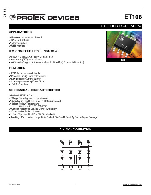
MECHANICAL CHARACTERISTICS
✔ Molded JEDEC SO-8 ✔ Weight 70 milligrams (Approximate) ✔ Available in Lead-Free Pure-Tin Plating(Annealed) ✔ Solder Reflow Temperature: Pure-Tin - Sn, 100: 260-270°C ✔ Consult Factory for Leaded Device Availability ✔ Flammability Rating UL 94V-0 ✔ 12mm Tape and Reel Per EIA Standard 481 ✔ Marking: Part Number, Logo, Date Code & Pin One Defined By Dot on Top of Package
2
元器件交易网
ET108
SO-8 PACKAGE OUTLINE & DIMENSIONS
PACKAGE OUTLINE
-A-
SO-8
8
5 -B - P
+ 0.010 (0.25 MM) M B M 4 PL
DIM A B C D F G J K P R
TAPE & REEL/BULK ORDERING NOMENCLATURE
1. Surface mount product is taped and reeled in accordance with EIA-481. 2. Suffix-T7 = 7 Inch Reel - 1,000 pieces per 12mm tape, i.e. ET108-T7. 3. Suffix-T13 = 13 Inch Reel - 2,500 pieces per 12mm tape, i.e., ET108-T13. 4. Suffix - LF = Lead-Free, Pure-Tin Plating, i.e., ET108-LF-T7. 5. No Suffix = Product Shipped in Tubes of 98 pcs per Tube.
AI108温控表说明书

KKAI108-A01C-201801304:(48*48)6:(96*48)7:(72*72)9:(96*96)48487296A型号H(Min)GB C D E F J4896729697.597.597.597.56.59999188.588.588.545.54567.5922525252545.59267.5924589.56791.5K(Min)25252525面板尺寸 侧面尺寸 开孔尺寸GJ-0+0.5A:版本T:TC输入 R:RTD输入10:单路输入B:一路报警输出 A: 无报警功能4: 48W*48H*100L 6:48W*96H*100L 7:72W*72H*100L9:96W*96H*100LAI108系列温控表R:继电器输出 S: 固态继电器输出 K:可控硅输出(需订做)序号型号主控方式11报警路数12SSRRELAYAI108-4/6/7/9-SB10-□AI108-4/6/7/9-RB10-□智能温控表使用说明书本说明书对温控表设置、配线及各部分名称等进行说明,使用本产品前,请认真阅读本说明书,在理解内容的基础上正确使用。
并请妥善保存,以便需要时参考。
⊙多种热电偶、热电阻信号类型可选⊙采用模糊PID 控制算法,且自整定无过冲⊙多种控制方式可选,具体请参照OT参数特点“ ”固态继电器输出绝缘电阻静电放电脉冲群抗扰度浪涌抗扰度电压暂降及短时中断抗扰度隔离耐压DC 24V 脉冲电平,带载<30mA输入、输出、电源对机壳>20MΩIEC/EN61000-4-2 Contact ±4KV /Air ±8KV perf.Criteria BIEC/EN61000-4-4 ±2KV perf.Criteria BIEC/EN61000-4-5 ±2KV perf.Criteria BIEC/EN61000-4-29 0%~70% perf.Criteria B信号输入与输出及电源1500VAC 1min,60V以下低压电路之间DC500V,1min整机重量约 400g机壳材质面贴材质停电数据保护面板防护等级安全标准外壳与面板基架PC/ABS (难燃度UL94V-0)PET(F150/F200)10年,可写数据次数100万次IP65(IEC60529)IEC61010-1 过电压分类Ⅱ,污染等级2,等级Ⅱ(加强绝缘)3、测量信号参数表:1、电气参数表:采样速度2次每秒供电电源继电器容量AC 250V /3A 额定负载寿命大于10万次AC/DC 100~240V (85-265V)三、主要技术参数二、常规型号说明一、仪表型号周围环境条件整机功耗存贮环境< 6VA室内使用,温度:0~50℃ 无结露,湿度:<85%RH,海拔小于2000m-10~60℃,无结露□:T:TC输入 /R:RTD输入可选四、通用面板名称五、外形及安装开孔尺寸1、出厂默认(PID加热)时的菜单流程:六、操作流程与菜单说明测量控制模式(常用菜单)注:接线如有变动,以实际仪表机壳上的接线图为准AI108-6AI108-7AI108-4AI108-9显示信息LLL/HHH排除方法检查输入是否断线;检查FH 值、FL 值;确定工作环境温度是否正常;检查输入信号选择是否正确;十、简单故障排除方法1、报警参数及输出逻辑图:符号说明:“☆”表示HY 部分,“▲”表示报警值,“ ”表示SV 值2.PID加热与冷却控制操作(适用于注塑机、挤出机等) 1)请将OT参数设定为3(加热冷却控制)。
LC821中文资料

5.0 A
RF CHARACTERISTICS (
SYMBOL Gps PARAMETER Common Source Power Gain Drain Efficiency Load Mismatch Tolerance MIN 10 55 TYP
8.0 WATTS OUTPUT )
MAX UNITS dB % 20:1 TEST CONDITIONS Idq = 0.40 A, Vds = 12.5 V, F = Idq = 0.40 A, Vds = 12.5 V, F =
0.1 0 2 4 1 10 100
ID & GM VS VGS
L2C 1 DIE ID, GM vs VG
ID
GM
Vgs in Volts6ຫໍສະໝຸດ 81012
14
Zin Zout
PACKAGE DIMENSIONS IN INCHES
Tolerance .XX +/-0.01
.XXX +/-.005 inches
TM
SILICON GATE ENHANCEMENT MODE RF POWER LDMOS TRANSISTOR 8.0 Watts Single Ended Package Style AC HIGH EFFICIENCY, LINEAR HIGH GAIN, LOW NOISE
o
ABSOLUTE MAXIMUM RATINGS ( T = 25 C )
500 MHz 500 MHz
η
VSWR
Relative Idq = 0.40 A, Vds = 12.5 V, F = 500 MHz
ELECTRICAL CHARACTERISTICS ( EACH SIDE )
ACS108资料

1/7ACS108-5Sx®November 1999-Ed:3BAC LINE SWITCHTO92ACS108-5SAnV DRM /V RRM =500VnAvalanche controlled device nI T(RMS)=0.8AnGate triggering current :I GT <10mA nSwitch integrated drivernDrive reference COM connected to the SOT223tabFEATURESThe ACS108belongs to the AC line switches built around the ASD ™concept.This high performance full planar technology device is able to control an 0.8A load.The ACS ™switch embeds a high voltage clamping structure to absorb the inductive turn-off energy and a gate level shifter driver to separate the digital controller from the main switch.It is triggered with a negative gate current flowing out of the gate pin.DESCRIPTIONOUTCOMGnNeeds no more external protection snubber &varistor.nEnables the equipment to meet IEC1000-4-5standard.nAllows straightforward connection of several SOT223devices on the same cooling pad.nReduces the switch component count by up to 80%.nInterfaces directly with the microcontroller.nEliminates any stressing gate kick back on the microcontroller.BENEFITSFUNCTIONAL DIAGRAMGCOM OUTONSDACS108ASD ™AC Switch FamilySOT223ACS108-5SNOUTCOMCOMGn AC Line switch for appliance control systems nDrive of low power high inductive or resistive loads like:-solenoid,relay,valve,dispenser -micro-motor -door lock-low power lamp bulb -pump -fanMAIN APPLICATIONSNote :For further technical information,please re-fer to the Application note AN1172.ACS108-5Sx2/7Symbol ParameterValue Unit V DRM V RRM Repetitive peak off-state voltage Tj =25°C 500V I T(RMS)RMS on-state current full cycle sine wave 50to 60HzTO92Tlead =60°C 0.8A TO92Tamb =60°C 0.3A SOT223Tamb =55°C 0.8A I TSM Non repetitive surge peak on-state current Tj initial =25⊃C,full cycle sine wave F =50Hz 7.3A F =60Hz 8A dI/dt Critical rate of rise of on-state current I G =20mA with tr =100nsRepetitive F =120Hz 20A/µs V PP Non repetitive line peak pulse voltage note 12kV Tstg Storage temperature range-40to +150°C Tj Operating junction temperature range0to +110°C TlMaximum lead temperature for soldering during 10s260°Cnote 1:according to test described by IEC 1000-4-5standard &Figure 3.ABSOLUTE RATINGS (limiting values)Symbol ParameterValue Unit P G (AV)Average gate power dissipation0.1W I GM Peak gate current (tp =20µs)1A V GMPeak positive gate voltage (respect to the pin COM)5VSWITCH GATE CHARACTERISTICS (maximum values)Symbol ParameterValue Unit Rth (j-a)Junction to ambientTO92150°C/W SOT223(*)60°C/W Rth (j-l)Junction to lead for full AC line cycle conduction TO9260°C/W Rth (j-t)Junction to tab for full AC line cycle conductionSOT22325°C/W(*):with 5cm 2copper (e=35µm)surface under tabTHERMAL RESISTANCESSymbol Test ConditionsValues Unit I GT V OUT =12V(DC)R L =140ΩTj=25°C MAX 10mA V GT V OUT =12V (DC)R L =140ΩTj=25°C MAX 1V V GD V OUT =V DRM R L =3.3k ΩTj=110°C MIN 0.2V I H I OUT =100mA gate openTj=25°C TYP 25mA MAX60mA I L I G =20mA Tj=25°CTYP 30mA MAX 65mA V TM IOUT =1.1A tp=380µsTj=25°C MAX 1.3V I DRM I RRM V OUT =V DRM V OUT =V RRMTj=25°C MAX 2µA Tj=110°C MAX 50µA dV/dt V OUT =400V gate open Tj=110°C MIN 500V/µs (dI/dt)c (dV OUT /dt)c=10V/µs Tj=110°C MIN 0.1A/ms V CLICL =1mAtp=1msTj=25°CTYP600VELECTRICAL CHARACTERISTICSFor either positive or negative polarity of pin OUT voltage respect to pin COM voltageACS108-5Sx3/7The ACS108device is well adapted to washing machine,dishwasher,tumble drier,refrigerator,water heater and cookware.It has been designed especially to switch ON and OFF low power loads such as so-lenoid,valve,relay,micro-motor,fan,pump,door lock and low wattage lamp bulb.Pin COM:Common drive reference to connect to the power line neutral Pin G:Switch Gate input to connect to the digital controller Pin OUT:Switch Output to connect to the LoadThe ACS ™switch is triggered with a negative gate current flowing out of the gate pin G.It can be driven di-rectly by the digital controller through a resistor as shown on the typical application diagram.Note that no protection device (zener or capacitor)should be added between gates and common terminals.The SOT223version allows several ACS108devices to be connected on the same cooling PCB pad which is the COM pin :this cooling pad can be then reduced,and the printed circuit layout is simplified.In appliances systems,the ACS108switch intends to drive low power load in full cycle ON /OFF mode.When the gate signal is removed,the load is switched off after a delay time that is equal to one half line cy-cle or one full line cycle depending on the load drive strategy.The turn off commutation characteristics of these loads can be classified in 3groups as shown in table 1.Thanks to its thermal and turn off commutation performances,the ACS108switch is able to drive with no additional turn off snubber,a resistive or inductive load up to 0.2A (when this load has to switch off within one half AC line cycle),an inductive load up to 0.6A or a resistive load up to 0.8A (when this load has to switch off within one full AC line cycle).AC LINE SWITCH BASIC APPLICATIONLOADIRMS(A)POWER FACTOR(dI/dt)c(A/ms)(dV/dt)c(V/µs)TURN-FF DELAY (ms)Door Lock Lamp <0.310.150.15<10<0.810.40.15<20Relay Valve Dispenser Micro-motor <0.1>0.7<0.05<5<10Pump Fan<0.2>0.2<0.1<10<10<0.6>0.2<0.3<10<20Table 1:Load grouping versus their turn off commutation requirement (230V AC applications).TYPICAL APPLICATION DIAGRAMAC MAINS LNST 72MCULOAD-VccL RGCOM OUTACS108ONSDACS108-5Sx4/7Fig 3:Overvoltage ruggedness test circuit for resistive and inductive loads according to IEC 1000-4-5standard.R =150Ω,L =5µH,V PP =2kV.Iout (2A/div)Vout (200V/div)dI/dt =100A/µsFig 4:Current and voltage of the ACS ™during IEC 1000-4-5standard test with a 220Ω-10µH load &V PP =2kV.Fig 1:Turn-off operation of the ACS108switch with an electro valve:waveform of the gate current I G ,pin OUT current I OUT &voltage V OUT .Fig 2:ACS108switch static characteristic.T ime (400µs/div)I OUT(10mA/div)V OUT (200V/div)I HV CL =650VI HV CLI OUTV OUTR LR G =220ΩV AC +V PPAC LINE &SURGEVOLT AGE GENERA TORGCOM OUTACSxxONSDAt the end of the last conduction half-cycle,the load current reaches the holding current level I H ,and the ACS ™switch turns off.Because of the inductance L of the load,the current flows through the avalanche diode D and decreases linearly to zero.During this time,the voltage across the switch is limited to the clamping voltage V CL .The energy stored in the inductance of the load depends on the holding current I H and the inductance (up to 10H);it can reach about 20mJ and is dissipated in the clamping section that is especially designed for that purpose.INDUCTIVE SWITCH-OFF OPERATIONThe ACS108switch is able to sustain safely the AC line transient voltages either by clamping the low en-ergy spikes or by breaking over under high energy shocks,even with high turn-on current rises.The test circuit of the figure 4is representative of the final ACS ™application and is also used to stress the ACS ™switch according to the IEC1000-4-5standard conditions.Thanks to the load,the ACS ™switch sustains the voltage spikes up to 2kV above the peak line voltage.It will break over safely even on resistive load where the turn on current rise is high as shown on figure 4.Such non repetitive test can be done 10times on each AC line voltage polarity.AC LINE TRANSIENT VOLTAGE RUGGEDNESSACS108-5Sx5/72550751001250.000.250.500.751.001.251.501.752.00IGT[Tj]/IGT[Tj=25°C]Tj(°C)Fig 5:Relative variation of gate trigger current versus junction temperature2550751001250.00.20.40.60.81.01.21.41.61.82.0IH[Tj]/IH[Tj=25°C]&IL[Tj]/IL[Tj=25°C]Tj(°C)Fig 6:Relative variation of holding &latching currents versus junction temperature0.50.7511.251.51.7520.050.070.10.20.30.40.50.60.8125IOUT (A)VTM (V)Fig 7:On state characteristics @Tj maxV TO =0.90V &R T =0.3Ω(maximum values)Pon V I R x I TO T RMS T T RMS =+...()()222ΠZth(j-a)/Rth(j-a)1E-31E-21E-11E+01E+11E+25E+20.010.101.00tp (s)Fig 9-1:Relative variation of the junction to ambient thermal impedance versus conducting pulse duration for the SOT223Standard foot print with 35µm copper layout thickness.1E-31E-21E-11E+01E+11E+25E+20.010.101.00Zth(j-a)/Rth(j-a)tp (s)Fig 9-2:Relative variation of the junction to ambient thermal impedance versus conducting pulse duration for the TO92.10203040506070809010011012000.20.40.60.81IT(RMS)(A)TO92SOT223(*)Tamb (°C)Fig 8:Maximum RMS switch current versus ambient temperature on inductive load (PF>0.1)and a low repetitive rate (F <1Hz)(*):with 5cm 2copper (e=35µm)surface under tabACS108-5Sx6/7PACKAGE MECHANICAL DATA SOT223A A1B e1D B1H EecVREF.DIMENSIONSMillimeters Inches Min.Typ.Max.Min.Typ.Max.A 1.800.071A10.020.001B 0.600.700.800.0240.0270.031B1 2.90 3.00 3.100.1140.1180.122c 0.240.260.320.0090.0100.013D 6.306.50 6.700.2480.2560.264e2.30.090e1 4.60.181E 3.30 3.50 3.700.1300.1380.146H6.707.007.300.2640.2760.287V 10°maxACS 108-5S ATMAC SwitchNumber of SwitchI 08=0.8ATRMSGate Sensitivity S =10mAA =TO92N =SO T223V 5=500VDRMORDERING INFORMATION12345102030405060708090100110120130Rth(j-a)(°C/W)S(Cu)(cm)2Fig.10:SOT223thermal resistance junction to ambient versus copper surface under tab (Epoxy printed circuit board FR4,copper thickness:35µm)ACS108-5Sx7/7Information furnished is believed to be accurate and reliable.However,STMicroelectronics assumes no responsibility for the consequences of use of such information nor for any infringement of patents or other rights of third parties which may result from its use.No license is granted by implication or otherwise under any patent or patent rights of STMicroelectronics.Specifications mentioned in this publication are subject to change without notice.This publication supersedes and replaces all information previously supplied.STMicroelectronics products are not authorized for use as critical components in life support devices or systems without express written ap-proval of STMicroelectronics.The ST logo is a registered trademark of STMicroelectronics©1999STMicroelectronics -Printed in Italy -All rights reserved.STMicroelectronics GROUP OF COMPANIESAustralia -Brazil -China -Finland -France -Germany -Hong Kong -India -Italy -Japan -MalaysiaMalta -Morocco -Singapore -Spain -Sweden -Switzerland -United Kingdom -U.S.A.PACKAGE MECHANICAL DATA TO92PlasticD F aEBACREF.DIMENSIONSMillimeters Inches Min.Typ.Max.Min.Typ.Max.A 1.350.053B 4.700.185C 2.540.100D 4.400.173E12.700.500F 3.700.146a0.450.017Ordering type Marking Package Weight Base qty Delivery modeACS108-5SA ACS08/5S TO920.2g 2500Bulk ACS108-5SNACS/085SSOT2230.123g1000Tape &reelTM :ASD and ACS are trademarks of STMicroelectronics .PACKAGE MECHANICAL DATA SOT223。
最新HX108-2收音机详细原理及讲解上课讲义
本课题的目的及意义
▪ 锡焊技术是电工的基本操作技能之一,通过 实习要求大家在初步掌握这一技术的同时, 注意培养自己在工作中耐心细致,一丝不苟 的工作作风。
▪ 收音机是最常用的家用电器之一,通过这次 实习,我们应该在了解其基本工作原理的基 础上学会安装、调试、使用 ,并学会排除一 些常见故障。
第一步:清点材料
▪ 注意
请按材料清单一一对应,记清每个元件的名称 与外形
提醒
▪ 要小心滚掉弹簧和螺丝 ▪ 清点完后请将暂时不用材料放回塑料袋备用。 ▪ 打开时请小心,不要将塑料袋撕破,以免零
件丢失。 ▪ 清点材料时请将机壳后盖当容器,将所有的
东西都放在里面 。
零 件1
电阻 共13只
零件 2
零件 3
中频放大器
中周滤波式中频耦电合变路压器
前级谐振 选频网络
本级谐振选 频网络
中频放大器的任务
电台发射的载波经过变频以 后得到的 “中频”电压是很弱 的(幅度很低,约数十毫伏) 必须利用电压放大器进行足够 地放大。
HX108-2装配图
HX108-2收音机的印刷电路
安装步骤
▪ 机械部件的安装调整 ▪ 焊接前的准备工作 ▪ 元器件的焊接与安装 ▪ 收音机故障的排除 ▪ 二 极 管、电容、电阻的 认识 ▪ 清点材料
调制信号
调制器
(声音信号)
×
调幅信号输出
载频信号 (高频信号)
长波:f<535kHz 中波:535kHz< f<1605kHz 短波:几MHz< f<10几MHz
载 波
调调
幅
制 波
与
调
调 幅
频波
HSP-108 8英寸两分频扬声器用户手册说明书

为了安全和方便安装请仔细阅读并妥善保管本说明书Please read this manual before using the apparatus and keep it for future referenceHSP-108 8-inch Two-way Loudspeaker深圳台电公司保留更改数据资料权,恕不事先通知。
Contents may change without prior announcement.Printed in Shenzhen 05/2022TAIDEN INDUSTRIAL CO.,LTD.无源8英寸两分频扬声器User's Manual用户手册V1.1398467产品概述Overview尺寸和背面板Dimensions and back panel配置了1×8"低音单元,以及1×2"高音压缩单元,由平面波导技术号角加载,实现水平覆盖50°~100°渐变,垂直覆盖60°,号角可旋转,使覆盖区域内声压以及频响更加均匀一致。
It is composed of 1×8" woofer and 1×2" tweeter. Loaded by PWH-Planar Waveguide Horn technology, to achieve 50°~100° gradient horizontal coverage, 60° vertical coverage, rotatable horn, to make the sound pressure and frequency response more uniform in the coverage area.技术参数频率响应...................................70Hz-20kHz (±3dB) 50Hz-25kHz (-10dB)灵敏度...............................................................96dB 标称阻抗.........................................................8 Ohm 额定功率................................................200W(AES)低音单元...........................1×8" 复合碳纤维振膜低音高音单元...........................1×2" 纳米碳纤维振膜高音标称覆盖角..............50°-100°H 渐变 ×60°V 非对称 可旋转号角最大声压级.................119dB SPL, 125 dB SPLpeak 输入接口................................................2路Speakon 箱体材料....................................桦木+黑色聚脲漆面尺寸(H×W×D )...................... 460×265×250(mm) 重量..................................................................9.8kgFrequency Range.........................70Hz-20kHz (±3dB) 50Hz-25kHz (-10dB)Sensitivity.............................................................96dB Nominal Impedance...........................................8 Ohm Rated Power.............................................200W (AES)Woofer ................................1×8"complex carbon fiberdiaphragm woofer Tweeter ...................................1×2" nano carbon fiberdiaphragm tweeter Coveragepattern.........50°-100° (H) gradient ×60° (V)asymmetric, rotatable horn Max SPL........................119dB SPL, 125dB SPL peak Input Interface......................................... 2 x Speakon Enclosure Material...........Birch + black polyurea finish Dimensions (H × W × D)................460×265×250(mm)Weight.................................................................9.8kg特点复合碳纤维+纳米碳纤维振膜 渐变式指向号角,可旋转Composite carbon fiber diaphragm + nano carbon fiber diaphragmGradient pointing horn, rotatableFeaturesSpecifications1. Treble horn2. Woofer3. Input/parallel interface (2Speakon)4&5&6&7. Hanging points (7×M8)7&8. P oints for HSP-108BKTU bracket 9. Rod socket (Ø35mm)Note: Installation accessories need to be purchased separately×1.高音号角2.低音单元3.输入/并联接口(2Speakon )4&5&6&7.吊挂点(7M8)7&8.HSP -108BKTU 支架连接点9.支撑杆插孔(Ø35mm )注:安装配件需另购××。
HX108-2七管半导体收音机的安装与调试实验报告(推荐五篇)
HX108-2七管半导体收音机的安装与调试实验报告(推荐五篇)第一篇:HX108-2七管半导体收音机的安装与调试实验报告电子产品工艺综合实训报告HX108-2七管半导体收音机的安装与调试所在系院:专业班级:学生学号:学生姓名:课程名称:指导教师:XXXX年 XX 月XX 日目录一、实训目的 (1)二、实训内容 (1)三、实训器材介绍 (1)四、原理描述 (2)五、实训步骤 (2)六、实训总结心得 (5)一、实训目的1.通过对收音机的安装、焊接及调试,了解电子产品的生产制作过程;2.按照图纸焊接元件,组装一台收音机,并掌握其调试方法;3.通过电路图,初步掌握简单电路元件装配、初步的焊接技术及对故障的诊断和排除;4.了解HX108-2 七管半导体收音机的原理。
熟练焊接的基本技巧;5.掌握电子元器件的识别及质量检验;6.学会利用工艺文件独立进行整机的装焊和调试,并达到产品质量要求;二、实训内容先要说明一下什么是超外差式收音机,最初的收音机属于直放式收音机,它的特点是,从天线上接收到的高频信号,在检波以前,一直不改变它原来的高频频率(即高频信号直接放大)。
它的缺点是,在接收频段的高端和低段的放大不一样整个波段的灵敏度不均匀。
如果是多波段收音机,这个矛盾更突出。
其次,如果要提高灵敏度,必须增加高频放大的级数,由此带来各级之间的统一调谐的困难,而且高频放大器增益做不高,容易产生自激。
如果能够把收音机接收到的高频信号,都变换成固定的中频信号进行放大检波。
由于中频频率比变换前的信号频率低,而且频率固定不变,所以任何电台的信号都能得到相等的放大量,同时总的放大量也可以较高。
三、实训器材介绍1.实训器材; 1.电烙铁一个,2.万用表一部,3。
HX108-2七管半导体收音机完整组件,电烙铁:是电子制作和电器维修的必备工具,主要用途是焊接元件及导线,按机械结构可分为内热式电烙铁和外热式电烙铁,按功能可分为无吸锡电烙铁和吸锡式电烙铁,根据用途不同又分为大功率电烙铁和小功率电烙铁。
UL1082-中文版

5.2 壳体材料应能适合于特定的应用要求,能将使用时可能引发火灾,电击或伤害人体的所有电气零件(电 源线除外)封闭起来。
5.3 判断壳体是否适用于特定的应用要求,其考虑因素有: (1) 机械强度; (2) 抗冲击性能; (3) 吸湿性能; (4) 燃烧性; (5) 耐腐蚀性能; (6) 在正常使用或非正常使用温度下壳体的抗变形性能。 对非金属材料壳体,见 UL 746C Standard for Polymeric Materials — Use in Electrical Equipment Evaluation 的壳体要求。金属材料壳体,按 34 章试验来检查其冲击性能。
流电压为 42.4V)。如果输入电路用串联阻抗来分压限流,再连接到线电压电路上,则该输入电路不 是低压电路,也不是隔离限压次级电路。见 11A.5。
版权所有人:TOMS.XU
未经许可,严禁拷贝 !
投诉电话:0755-86027268
HOUSEHOLD ELECTRIC COFFEE MAKERS AND BREWING-TYPE APPLIANCES – UL 1082(家用电咖啡壶及酿造类器具)
5.8 壳体结构应使得熔融金属,绝缘材料的燃烧,火花等不会落下到支撑表面上。
5.9 为满足 5.8 节的要求,对于底部开孔的壳体,如为下列情况,必须在孔位上方或下方加挡板: A. 位于马达下方,但以下情况除外:
1. 马达或器具的结构零件已有等同功能的挡板。
2. 马达带保护装置,使得当马达在下列故障情况下通电时,没有绝缘材料燃烧颗粒或熔融金 属落到器具支撑表面上:
2
31. 高压测试
29
32. 断开发热丝测试
29
33. 电源线拉力测试
30
FCK-821E技术及使用说明书

FCK-821E微机测控装置技术说明书(R1版 Ver 1.00)许继电气股份有限公司XJ ELECTRIC CO.,LTD.目录1 概述 (1)1.1应用范围 (1)1.2产品特点 (1)1.3保护配置 (1)2 技术指标 (3)2.1基本电气参数 (3)2.2主要技术指标 (3)2.3环境条件 (5)3 装置功能 (6)3.1遥测 (6)3.2遥信 (6)3.3遥控 (6)3.4遥调 (6)3.5保护功能 (6)4 定值清单及整定说明 (7)4.1测控/1保护定值 (7)4.2测控/2保护定值 (8)4.3测控/3保护定值 (9)4.4测控/4保护定值 (10)4.5定值整定说明 (11)5 装置硬件介绍 (12)5.1结构与安装 (12)5.2插件布置图 (13)5.3装置端子 (14)5.4装置背板接线说明 (15)6 使用说明 (16)6.1指示灯说明 (16)6.2调试接口和键盘说明 (16)6.3命令菜单 (17)6.4主界面显示及菜单说明 (17)6.5液晶显示说明 (29)7 调试说明 (29)7.1调试注意事项 (29)7.2开关量输入检查 (29)7.3开出回路检查 (29)7.4模拟量输入检查 (30)7.5整组试验 (30)7.6装置异常信息说明及处理意见 (30)7.7事故分析注意事项 (30)8 订货须知 (31)1概述1.1应用范围FCK-821E微机测控装置适用于电力系统110kV及以下电压等级,作为变电站自动化系统中的数据采集和控制单元,可根据使用场合灵活将装置配置为测控/1、测控/2、测控/3、测控/4。
测控/1适用于公共测控;测控/2适用于主变测控;测控/3适用于小电流系统PT测控;测控/4适用于大电流系统PT测控。
1.2产品特点✧系列装置元器件全部采用军品或工业品,稳定性、可靠性高,可以在工业恶劣环境下稳定运行;✧采用SoC解决方案,数据处理、逻辑运算和信息储存能力强,运行速度快,可靠性高。
WH108资料

¡¾0.1
0 .05 ¾¡
¡¾0. 05
1.75
2.0
0. 2
¡¾0 .05
1. 85
3.5 (2 .7 5)
4.0
¡¾0 .1
0.5
¡¾0.08
0.95
¡¾0.0
5
8.0¡¾Βιβλιοθήκη .20.3 5¡¾0.0
5
18 0
+0 -3
11.4 9
0 .3 ¾¡
2
0 .2 ¾¡
22 13
¡¾0 .2
Labe l
LED Surfa c e te mp e ra ture
C Æ¡
Oper ati o n he at ing 240
150
~
Pre- hea ting
Tem p era ture ris e : 5¡Æ C/sec .
Co olin g: -5 ¡ÆC /s ec .
120
0 60 to 120 sec. 5sec. ma x
(Ta=25¡É ) Unit
V
*1 IFM conditions: Pulse width Tw¡Â 0.1ms, Duty ratio¡Â 1/10
3. Electro-Optical Characteristics Characteristics Forward Voltage Reverse Current Luminous Intensity *2 Chromaticity Coordinates *3 Symbol VF IR IV X Y Viewing Angle : Y Direction 2¥è
(2) Lead-Free Solder -Preliminary heating to be at 150¡É max. for 2 minutes max. -Soldering heat to be at 260¡É max. for 10 seconds max.
HO1081中文资料
RF Monolithics, Inc.Phone: (972) 233-2903Fax: (972) 387-8148E-mail: info@ Page 1 of 2RFM Europe Phone: 44 1963 251383Fax: 44 1963 251510 ©1999 by RF Monolithics, Inc. The stylized RFM logo are registered trademarks of RF Monolithics, Inc.HO1081-111201Electrical CharacteristicsCharacteristicSym Notes Minimum Typical Maximum Units Operating Frequency Absolute Frequency f O 1, 71089.7501090.01090.250MHz Tolerance from 1090.0 MHz∆f O ±250kHz RF Output Power P O3, 6+10+12+14dBm Discrete SpuriousSecond Harmonics2, 3, 4-25-20dBcThird and Higher Harmonics-35-30Nonharmonic <-100-80SSB Phase Noise 1 kHz Offset 2, 3, 4-100-90dBc/Hz 10 kHz Offset -120-110RF Impedance Nominal Impedance Z O 350ΩOperating Load VSWR G L 3, 5 1.5:1DC Power SupplyOperating Voltage V CC 3, 611.7512.012.25VDC Operating CurrentI CC 3540mA Operating Ambient TemperatureT A3, 6-55+105°CLid Symbolization (YY=Year, WW=Week)RFM HO1081 YYWW•SAW Frequency Stabilization•Fundamental-Mode Oscillation at 1090.0 MHz •Ideal for IFF Transponder ApplicationsThe frequency of this oscillator is stabilized by surface-acoustic-wave (SAW) technology. This results in ex-cellent performance from a compact, rugged, hermetically-sealed oscillator operating at the fundamental fre-quency of 1090.0 MHz. The highly-reliable HO1081 is designed for use in identify-friend-or-foe (IFF) radar transponders in military aviation. Military Screening is available as an option. The HO1081 is a high-perfor-mance version of the HO1079 oscillator.Absolute Maximum RatingsRatingValue Units DC Supply Voltage 0 to +13VDC Ambient TemperaturePowered -55 to +105°CStorage-55 to -1251090.0 MHzSAW OscillatorHO1081CAUTION: Electrostatic Sensitive Device. Observe precautions for handling. COCOM CAUTION: Approval by the U.S. Department ofCommerce is required prior to export of this device.Notes:1.One or more of the following United States patents apply: 4,616,197; 4,610,681; and 4,761,616.2.Unless noted otherwise, all specifications are listed at T A = +25°C ±2°C, V CC = nom-inal voltage ±0.01 VDC, and load impedance = 50 Ω with VSWR ≤ 1.5:1.3.The design, manufacturing process, and specifications of this device are subject to change without notice.4.Applies to oscillator only and not to sidebands caused by external electrical ormechanical sources. (Dedicated external voltage regulation with low-frequency filter-ing for the DC power supply and proper circuit board layout are recommended for optimum spectral purity.)5.For specified maximum operating load VSWR (any angle) at F O . (No instability or damage will occur for any passive load impedance.)6.For any combination of V CC and T A within the specified operating ranges.7.Applies for any combination of Note 5 and 6 conditions.BLOCK DIAGRAMELECTRICAL CONNECTIONSGround 11090.0 MHz SAW OscillatorRF Monolithics, Inc.Phone: (972) 233-2903Fax: (972) 387-8148E-mail: info@ Page 2 of 2RFM Europe Phone: 44 1963 251383Fax: 44 1963 251510 ©1999 by RF Monolithics, Inc. The stylized RFM logo are registered trademarks of RF Monolithics, Inc.HO1081-111201DIP16-8 Metal Dual-Inline Package with 8 leads in a 16-lead DIP configurationDimensionmmInchesMINMAX MIN MAX A —25.02—0.985B —12.83—0.505C — 6.35—0.250D 0.400.510.0160.020E 0.64 Nominal 0.025 NominalF 7.62 Nominal 0.300 NominalG 2.54 Nominal 0.100 NominalH 17.78 Nominal 0.700 Nominal K 3,39 6.730.1300.265L 1.30—0.051—M —11.18—0.440N —22.60—0.890R1.752.260.0690.089Top ViewBottom ViewD(8 Places)B MA NEPin 1 Mark (Optional)(4 Places)LCKFR(3 Places)H G(4 Places)12789101516。
多路通TC-108H程控电话交换机说明书
铃次数为 4 次,用户根据需要可修改为 2—6 次。 (7)恢复出厂初始设置:可全部取消原来设置,恢复出厂初始状态,再重新设置即
可。 24、断电保留编程设备(停电记忆)
当按编程功能修改设置时,最后设置结果则可保留,断开小总机电源,40 年内再通 电均可保留修改设置。 25、屏蔽呼叫功能
错误修正:若转到错误分机,此时主叫分挂机 3—5 秒以上提机,则外线主动返 回主转机,再拨正确分机号码即可。
-4-
广州市白云区百新电器厂
产品说明书
5. 三方通话 (1) 某分机应答外线后,若要另一分机加入通话,则先按“*”再按分机号码(1
—8),主叫方听等待音(不要挂机),外方也听等待音,被叫方响铃,摘机即可与外 线实现三方通话。 错误修正:与(4、外线转移)相同。
用户录音后,可自行监听录音效果。 6、人工值班
如选用人工值班方式,外电打入时,各分机轮流响铃或指定值班分机响铃。 7、多次转接,自动纠错,转接保持
外面电话打入,A 分机接听后可以转 B 分机,B 分机接听后转 C 分机,转接次数不 限,转接过程中输错号码不要紧,只需重新输入正确号码,转接后主转分机听到等待音 即可挂机,而不用等被转分有无摘机,线路会自动保持而不中断(外线听等待音。)
注:两分机通话时,每隔 2 秒会听到“嘟”一声提示音,提醒用户外线正在等待通 话。
—以下编程功能全部在 1 号分机操作— ·操作正确会听到“嘟……”一声证实音,再听到拨号音可继续输入。 ·操作错误会听到忙音,需挂机重新操作。 7. 编程功能 用户如需要,可设置(取消)电脑话务员功能、修改数码录音、防盗打、免打扰、 市话及长途等字头限制,限时功能,传真接口功能及传真机延迟启动次数等功能(全部 设置或取消均在双音频 TONE 状态进行)。 (1) 免打扰设置 操作:*41(1—8) 注:(1—8)表示 1、2、3、4、5、6、7、8 号分机。 例:需设置 3 号分机免打扰 操作:提 1 号分机→听到拨号音→按*413→设置完成(取消免打扰则重新操作一次即 可)。
CK108 注塑机控制系统 说明书V1.0
欢迎使用本公司注塑机控制系统安全注意事项(安装前请务必阅读)危险注意PORCHESON T EC HN OL OG Y CO.,LTDCK108操作手册软件版本V1.02003.03版版权所有,未经允许翻印必究目录第一章系统配置及安装1.产品配置及说明2.PS 控制系统特点810AM 全计算机控制所有功能及温度采用高亮度L CD 液晶显示画面,640*480点7.4、10.4、寸寸单色/彩色(选用)系统采用多C PU 设计,运算速度快,控制精确,稳定性高控制主机采用模块化设计,安装省时,维修迅速具备Real Tim e 功能,可实时显示日期和时间输入、输出皆有L ED 指示灯,检测维护很方便具备屏幕保护功能,6分钟未操作时自动OFF输入、输出采用光藕合电路,可隔离外部线路干扰6路标准DA 比例输出,最大电流输出3A (PS800AM 为3路)射咀温度可开环或闭.环控制自我检测故障功能,报警显示及语音提示比例微积分(PID )自学习温度控制,11段温度多种抽芯及绞牙程序,适合不同类型的抽芯和绞牙控制多语言文字可选择,实时动态显示80组模具资料储存,可中、英文输入模具名称,实时操作帮助温度可一周预约定时,操作更便利。
包装模数设定功能,产量六位数,可设定包装模数检示画面可检查所有输入、输出点及按键的动作状态密码设定及资料锁定,可避免操作者任意更改成型资料,影响产品品质压力、流量、背压数字化预调,适合各种厂牌比例阀,更好的线性比例调整多种射胶方式,7段射胶,3级保压6路AD 电子尺/压力反馈具有远程通讯功能,可为用户远距离编写程序以及更换不同版本软件由一台计算机主机连网管理1-255台注塑机生产,能准确统计每台机生产情况,生产数据打印,方便管理3.电脑控制系统的安装及调试3.1控制系统安装时注意事项本控制系统设计非常简洁,键盘与主机箱的连接只有壹条15芯屏蔽电缆,安装连接相当(1)主控制箱安装时尽量采用封闭式电箱,要具有良好通风、防油、防尘的条件加装排风扇上防尘过滤网,保持电箱温度在60℃以下。
RCH108NP-3R7M中文资料

2.2μH~8.2μH 10μH~1.0mH
at 7.96MHz at 1kHz
※2: Rated current: The DC current at which the inductance decreases 90% of it’s initial value or when △t=40℃, whichever is lower(Ta=20℃) ※3:Please give sufficient consideration to the thick wire used when mounted into the P.C.B..
Type: RCH-108
◆ Specification
Part Name RCH1Ø8NP-2R2M RCH1Ø8NP-2R7M RCH1Ø8NP-3R7M RCH1Ø8NP-4R7M RCH1Ø8NP-6R2M RCH1Ø8NP-8R2M RCH1Ø8NP-1ØØM RCH1Ø8NP-12ØM RCH1Ø8NP-15ØM RCH1Ø8NP-18ØM RCH1Ø8NP-22ØM RCH1Ø8NP-27ØM RCH1Ø8NP-33ØK RCH1Ø8NP-39ØK RCH1Ø8NP-47ØK RCH1Ø8NP-56ØK RCH1Ø8NP-68ØK RCH1Ø8NP-82ØK RCH1Ø8NP-1Ø1K RCH1Ø8NP-121K RCH1Ø8NP-151K RCH1Ø8NP-181K RCH1Ø8NP-221K RCH1Ø8NP-271K RCH1Ø8NP-331K RCH1Ø8NP-391K RCH1Ø8NP-471K RCH1Ø8NP-561K RCH1Ø8NP-681K RCH1Ø8NP-821K RCH1Ø8NP-1Ø2K ※1:Measuring frequency: Stamp 2R2M 2R7M 3R7M 4R7M 6R2M 8R2M 100M 120M 150M 180M 220M 270M 330K 390K 470K 560K 680K 820K 101K 121K 151K 181K 221K 271K 331K 391K 471K 561K 681K 821K 102K Inductance [Within] ※1 2.2μH 2.7μH 3.7μH 4.7μH 6.2μH 8.2μH 10μH 12μH 15μH 18μH 22μH 27μH 33μH 39μH 47μH 56μH 68μH 82μH 100μH 120μH 150μH 180μH 220μH 270μH 330μH 390μH 470μH 560μH 680μH 820μH 1.0mH ± ± ± ± ± ± ± ± ± ± ± ± ± ± ± ± ± ± ± ± ± ± ± ± ± ± ± ± ± ± ± 20 % 20 % 20 % 20 % 20 % 20 % 20 % 20 % 20 % 20 % 20 % 20 % 10 % 10 % 10 % 10 % 10 % 10 % 10 % 10 % 10 % 10 % 10 % 10 % 10 % 10 % 10 % 10 % 10 % 10 % 10 % D.C.R. (Ω) [Max.] (at 20℃) 8.5m 9.6m 10.9m 11.7m 15.3m 17.0m 27.0m 31.0m 36.0m 49.0m 55.0m 62.0m 79.0m 87.0m 99.0m 0.13 0.14 0.16 0.21 0.24 0.32 0.35 0.45 0.61 0.69 0.78 1.0 1.2 1.4 1.8 2.1 Rated Current (A) ※2 7.9 7.2 6.3 5.7 5.3 5.0 4.5 4.1 3.7 3.4 3.1 2.8 2.5 2.3 2.1 1.9 1.7 1.6 1.4 1.3 1.2 1.1 0.96 0.87 0.79 0.72 0.66 0.60 0.55 0.50 0.45 S.R.F. (MHz) <Ref.> 46 35 32 28 26 18 14 10 9 17 16 13 12 11 10 8.6 7.6 7.4 6.5 6.2 5.1 4.6 4.3 4.0 3.7 3.2 3.0 2.8 2.6 2.3 2.1 Mounting holes (mm) ※3 1.4 1.4 1.4 1.4 1.4 1.4 1.2 1.2 1.2 1.4 1.4 1.4 1.2 1.2 1.2 1.2 1.2 1.2 1.2 1.2 1.0 1.0 1.0 1.0 1.0 1.0 1.0 1.0 1.0 1.0 1.0
GNR20D821K中文资料

GNR20D□□□ □□□K □□□
MODEL DATE
PAGE
5/5
ELECTRICAL CHARACTERISTICS
VARISTOR VOLTAGE CLAMPING VOLTAGE (MAX.) RATED WATTAGE (MAX.) SURGE CURRENT (8/20μs) μ Itm(A)
CSA C22.2 No.1
VDE 42000 5938 Approved Approved Approved Approved Approved Approved
LR105317
3. STRUCTURE
NO. 3.1 3.2 3.3 3.4 ITEM Main Material Zinc Oxide GNR, Part number, UL, CSA(or CUL) and VDE recognized component mark, Date code Without dirt and crack, marking should be clear
MODEL DATE
PAGE
3/5
TABLE
Tmax. 4.3 4.5 4.8 4.1 4.3 4.5 4.7 4.5 4.1 4.3 4.5 4.8 4.2 4.3 4.4 4.5 4.6 4.8 4.9 5.1 5.2 5.4 5.6 5.7 5.8 6.1 6.4 6.7 6.8 7.0 7.1 7.3 7.7 11.7 Unit:mm
1 TIME
REV.
Oct. 05, 2001 B01
SURGE LIFE
MAXIMUM ENERGY (10/1000μs) μ Wtm(joule) 13.0 16.0 19.0 24.0 28.0 34.0 41.0 49.0 56.0 70.0 85.0 106.0 130.0 140.0 155.0 168.0 190.0 210.0 228.0 255.0 275.0 303.0 350.0 382.0 382.0 382.0 382.0 420.0 440.0 460.0 510.0 565.0 620.0 1020.0
ACS108-8SN 产品说明书

SOT-223GCOM Common drive reference to connect to the mainsOUTOutput to connect to the load.GGate input to connect to the controller through gate resistorFeatures•Enables equipment to meet IEC 61000-4-5 surge with overvoltage crowbar technology•High noise immunity against static dV/dt and IEC 61000-4-4 burst •Needs no external protection snubber or varistor•Reduces component count by up to 80% and Interfaces directly with the micro-controller•Common package tab connection supports connection of several alternating current switches on the same cooling pad•V CL gives headroom before clamping then crowbar actionApplications•Alternating current on/off static switching in appliances and industrial control systems•Driving low power high inductive or resistive loads like:–relay, valve, solenoid, dispenser –pump, fan, low power motor, door lock, air flow dumper –lampDescriptionThe ACS108-8SN belongs to the AC switch range (built with A. S. D.® technology).This high performance switch can control a load of up to 0.8 A.This device switch includes an overvoltage crowbar structure to absorb the inductive turn-off energy, and a gate level shifter driver to separate the digital controller from the main switch. It is triggered with a negative gate current flowing out of the gate pin.Note:®: A.S.D. is a registered trademark of STMicroelectronics Note:TM: ACS is a trademark of STMicroelectronics0.8 A - 800 V overvoltage protected AC switch (ACS™)ACS108-8SNDatasheet1CharacteristicsTable 1. Absolute maximum ratings (T amb = 25 °C, unless otherwise specified)1.according to test described by standard IEC 61000-4-5, see Figure 17. Overvoltage ruggedness test circuit for resistive andinductive loads, T amb = 25 °C (conditions equivalent to IEC 61000-4-5 standard) for conditionsTable 2. Electrical characteristics (T j = 25 °C, unless otherwise specified)1.Minimum I GT is guaranteed at 10% of I GT max.Table 3. Static electrical characteristics1.For both polarities of OUT pin referenced to COM pinTable 4. Thermal characteristics1.1Characteristics (curves)Alternating current mains switch - basic application 2Alternating current mains switch - basic applicationThe ACS108 switch is triggered by a negative gate current flowing from the gate pin G. The switch can be drivendirectly by the digital controller through a resistor as shown in Figure 15. Typical application schematicThanks to its overvoltage protection and turn-off commutation performance, the ACS108 switch can drive a smallpower high inductive load with neither varistor nor additional turn-off snubber.Figure 15. Typical application schematic2.1Protection against overvoltage: the best choice is ACSIn comparison with standard Triacs the ACS108 is over-voltage self-protected, as specified by the parameter V CL.This feature is useful in two operating conditions: in case of turn-off of very inductive load, and in case of surgevoltage that can occur on the electrical network.2.1.1High inductive load switch-off: turn-off overvoltage clampingWith high inductive and low rms current loads the rate of decrease of the current is very low. An overvoltage canoccur when the gate current is removed and the OUT current is lower than I H.As shown in Figure 16. Switching off of a high inductive load - typical clamping capability of ACS108 (T amb = 25°C), at the end of the last conduction half-cycle, the load current decreases ① . The load current reaches theholding current level I H② , and the ACS turns off ③ . The water valve, as an inductive load (up to 15 H), reactsas a current generator and an overvoltage is created, which is clamped by the ACS ④ . The current flows throughthe ACS avalanche and decreases linearly to zero. During this time, the voltage across the switch is limited to theclamping voltage V CL. The energy stored in the inductance of the load is dissipated in the clamping section that isdesigned for this purpose. When the energy has been dissipated, the ACS voltage falls back to the mains voltagevalue (230 V rms, 50 Hz) ⑤.Figure 16. Switching off of a high inductive load - typical clamping capability of ACS108 (T amb = 25 °C)2.1.2Alternating current mains transient voltage ruggednessThe ACS108 switch is able to withstand safely the AC mains transients either by clamping the low energy spikesor by breaking-over when subjected to high energy shocks, even with high turn-on current rises.The test circuit shown in Figure 17. Overvoltage ruggedness test circuit for resistive and inductive loads, T amb =25 °C (conditions equivalent to IEC 61000-4-5 standard) is representative of the final ACS108 application, and isalso used to test the AC switch according to the IEC 61000-4-5 standard conditions. Thanks to the load limitingthe current, the ACS108 switch withstands the voltage spikes up to 2 kV above the peak mains voltage. Theprotection is based on an overvoltage crowbar technology. Actually, the ACS108 breaks over safely as shown inFigure 18. Typical current and voltage waveforms across the ACS108 (+2 kV surge, IEC 61000-4-5 standard).The ACS108 recovers its blocking voltage capability after the surge (switch off back at the next zero crossing ofthe current).Such non-repetitive tests can be done 10 times on each AC mains voltage polarity.Figure 17. Overvoltage ruggedness test circuit for resistive and inductive loads, T amb = 25 °C (conditionsequivalent to IEC 61000-4-5 standard)Figure 18. Typical current and voltage waveforms across the ACS108 (+2 kV surge, IEC 61000-4-5standard)3Package informationIn order to meet environmental requirements, ST offers these devices in different grades of ECOPACK packages,depending on their level of environmental compliance. ECOPACK specifications, grade definitions and product status are available at: . ECOPACK is an ST trademark.3.1SOT-223 package information•Epoxy meets UL94, V0•Lead free plating + halogen-free molding resinFigure 19.SOT-223 package outlinePackage informationSOT-223 package informationTable 5. SOT-223 package mechanical data1.Inches only for referenceFigure 20. SOT-223 footprint (dimensions in mm)Ordering information4Ordering informationFigure 21. Ordering information schemeACS 1 08 - 8 S N -TRAC switch seriesNumber of switchesCurrent08 = 0.8 A rmsVoltage8 = 800VGate currentS = 10 mAPackageN =SOT-223PackingTR =Tape and reel 7”(SOT-223, 1000 pieces)Table 6. Ordering information1.first row = ACS, second row = 108, third row = 8SRevision historyTable 7. Document revision historyIMPORTANT NOTICE – PLEASE READ CAREFULLYSTMicroelectronics NV and its subsidiaries (“ST”) reserve the right to make changes, corrections, enhancements, modifications, and improvements to ST products and/or to this document at any time without notice. Purchasers should obtain the latest relevant information on ST products before placing orders. ST products are sold pursuant to ST’s terms and conditions of sale in place at the time of order acknowledgement.Purchasers are solely responsible for the choice, selection, and use of ST products and ST assumes no liability for application assistance or the design of Purchasers’ products.No license, express or implied, to any intellectual property right is granted by ST herein.Resale of ST products with provisions different from the information set forth herein shall void any warranty granted by ST for such product.ST and the ST logo are trademarks of ST. For additional information about ST trademarks, please refer to /trademarks. All other product or service names are the property of their respective owners.Information in this document supersedes and replaces information previously supplied in any prior versions of this document.© 2019 STMicroelectronics – All rights reserved。
