TN3019A_00中文资料
1590A中文资料

1590A Paired - Category 5e Unbonded-Pair CableFor more information pleasecall1-800-Belden1See Put-ups and ColorsRelated Documents : No. 8 forDataTwist Cables (ModifiedWestern Electric).pdf Description:24 AWG solid bare copper conductors, plenum, FEP Teflon® insulation, twisted pairs, rip cord, see color code chart (below), Flamarrest®jacket (natural or blue).SUITABLE APPLICATIONS:Suitable Applications Premise Horizontal Cable, Gigabit Ethernet, 100BaseTX, 100BaseVG ANYLAN,155ATM, 622ATM, NTSC/PAL Component or Composite Video, AES/EBU,Digital Video, RS-422PHYSICAL CHARACTERISTICS:CONDUCTOR:Number of Pairs 2Total Number of Conductors 4AWG24Stranding SolidConductor Material BC - Bare CopperINSULATION:Insulation Material FEP - Fluorinated Ethylene PropylenePair Color Code Chart :Number Color1White/Blue Stripe & Blue Number Color2White/Orange Stripe & OrangeOUTER SHIELD:Outer Shield Material UnshieldedOUTER JACKET:Outer Jacket Material Trade Name Flamarrest®Outer Jacket Material LS PVC - Low Smoke Polyvinyl Chloride Outer Jacket Ripcord YesOVERALL NOMINAL DIAMETER:Overall Nominal Diameter.165 in.1590A Paired - Category 5e Unbonded-Pair CableMECHANICAL CHARACTERISTICS:Operating Temperature Range-20°C To +75°CBulk Cable Weight21 lbs/1000 ft.Max. Recommended Pulling Tension13 lbs.Min. Bend Radius (Install)0.7 in.APPLICABLE SPECIFICATIONS AND AGENCY COMPLIANCE:APPLICABLE STANDARDS:NEC/(UL) Specification CMP, UL444CEC/C(UL) Specification CMPEU CE Mark (Y/N)YesEU RoHS Compliant (Y/N)YesEU RoHS Compliance Date (mm/dd/yyyy):01/01/2005TIA/EIA Specification568-B.2 Category 5eOther Specification NEMA WC-63.1 Category 5e, UL verified to Category 5eFLAME TEST:UL Flame Test NFPA 262CSA Flame Test FT4, FT6PLENUM/NON-PLENUM:Plenum (Y/N)YNon-Plenum Number1588A, 1588RELECTRICAL CHARACTERISTICS:Nom. Mutual Capacitance @ 1 KHz14 pF/ftMaximum Capacitance Unbalance (pF/100 m)330 pF/100 mNominal Velocity of Propagation72 %Maximum Delay (ns/100 m)538 @ 100MHz ns/100 mMaximum Delay Skew (ns/100m)45 ns/100 mMaximum Conductor DC Resistance @ 20 Deg. C9.38 Ohms/100 mMaximum DCR Unbalance @ 20 Deg. C 5 %Max. Operating Voltage - UL300 V RMSELECTRICAL CHARACTERISTICS - PREMISE:Premise Cable Electricals Table 1 :1590A Paired - Category 5e Unbonded-Pair CableFrequency (MHz)Max.Attenuation(dB/100 m)Min. NEXT(dB)Min. PSNEXT(dB)Min. ACR (dB)Min. PSACR(dB)Min. ReturnLoss (dB)Min.StructuralReturn Loss(dB)1 2.065.362.363.060.320.023.0 4 4.156.353.351.049.223.023.0 8 5.851.848.846.043.024.524.5 10 6.550.347.343.040.825.025.0 168.247.344.339.036.025.025.0 209.345.842.836.533.525.025.0 2510.444.341.333.930.924.324.3 31.2511.742.939.931.028.223.623.6 62.517.038.435.422.019.021.521.5 10022.035.332.314.010.320.120.1 15528.132.529.5 4.4 1.415.820032.030.827.8 4.0 1.015.0Premise Cable Electricals Table 2 :Frequency (MHz)Input (Unfitted)Impedance (Ohms)Fitted Impedance(Ohms)Min. ELFEXT (dB)Min. PSELFEXT (dB)1100 ± 15100 ± 1563.860.84100 ± 15100 ± 1551.748.78100 ± 15100 ± 1545.742.710100 ± 15100 ± 1543.840.816100 ± 15100 ± 1539.736.720100 ± 15100 ± 1537.734.725100 ± 15100 ± 1535.832.831.25100 ± 15100 ± 1533.930.962.5100 ± 15100 ± 1527.824.9100100 ± 15100 ± 1523.820.8155100 ± 25100 ± 1519.916.9200100 ± 25100 ± 1517.714.7NOTES:Notes Jacket sequentially marked at 2 ft. intervals. Third party verified to TIA/EIA-568-B.2, Category 5e.PUT-UPS AND COLORS:Item Description Put-Up (ft.)Ship Weight (lbs.)Jacket Color Notes1590A 8771000 2 PR #24 FEPFLMRST1000 16NATURAL C1590A D151000 2 PR #24 FEPFLMRST1000 16BLUEC = CRATE REEL PUT-UP.Revision Number: 2 Revision Date: 04-18-20061590A Paired - Category 5e Unbonded-Pair Cable© Copyright 2006 Belden, IncAll Rights Reserved.Although Belden ("Belden") makes every reasonable effort to ensure their accuracy at the time of this publication, information and specifications described herein are subject to error or omission and to change without notice, and the listing of such information and specifications does not ensure product availability.Belden provides the information and specifications herein on an "AS IS" basis, with no representations or warranties, whether express, statutory or implied. In no event will Belden be liable for any damages (including consequential, indirect, incidental, special, punitive, or exemplary damages) whatsoever, even if Belden has been advised of the possibility of such damages, whether in an action under contract, negligence or any other theory, arising out of or in connection with the use, or inability to use, the information or specifications described herein.All sales of Belden products are subject to Belden's standard terms and conditions of sale.Belden believes this product to be in compliance with the following environmental regulations: California Proposition 65 Consent Judgment For Wire & Cable Mfgs.(San Francisco Superior Court Nos. 312962 And 320342); EU RoHS (Directive 2002/95/EC, 27-Jan-2003);Material manufactured prior to the compliance date may still be in stock at Belden facilities and in our Distributor's inventory. EUELV (Directive 2000/53/EC, 18-Sept-2000); EU WEEE (Directive 2002/96/EC, 27-Jan-2003); And EU BFR (Directive 2003/11/EC, 6-Feb-2003). The information provided in this Product Disclosure, and the identification of materials listed as reportable or restricted within the Product Disclosure, is correct to the best of Belden's knowledge, information and belief at the date of its publication. The information provided in the Product Disclosure is designed only as a general guide for the safe handling, storage, and any other operation of the product itself or the one that it becomes a part of. This Product Disclosure is not to be considered a warranty or quality specification. Regulatory information is for guidance purposes only. Product users are responsible for determining the applicability of legislation and regulationsbased on their individual usage of the product.Belden declares this product to be in compliance with EU LVD (Low Voltage Directive 73/23/EEC), as amended by directive 93/68/EEC.。
部件的名字和型号说明书
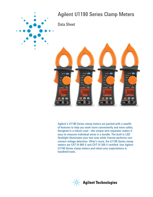
Agilent U1190 Series Clamp Meters Data SheetAgilent’s U1190 Series clamp meters are packed with a wealth of features to help you work more conveniently and more safely. Designed in a robust case—the unique wire separator makes it easy to measure individual wires in a bundle. The built-in LED flashlight illuminates your test area while Vsense performs non-contact voltage detection. What’s more, the U1190 Series clamp meters are CAT III 600 V and CAT IV 300 V certified. Use Agilent U1190 Series clamp meters and retool your expectations in handheld tools.FeaturesThe U1190 Series clamp meters include:• Unique wire separator to separate wires from a bundle• Vsense to perform non-contact voltage detection1• Built-in LED flashlight to illuminate test area1• Visual (backlight alert) and audible continuity indication in noisy environments• Current measurement up to 600 A2• Digital multimeter (DMM) with resistance, capacitance1, DCV, ACV, DCA3, ACA, DCµA3 and ACµA3 measurement capabilities• Continuity and diode test measurements• CAT III 600 V / CAT IV 300 V safety rating1. Exclusive to U1192A, U1193A, and U1194A.2. Exclusive to U1193A and U1194A.3. Exclusive to U1194A.Unique wire separator with abuilt-in flashlightThe U1190 Series clamp meters arebuilt to perform in the environmentsyou work. The unique wire separatorallows you to effortlessly isolate andperform measurements on individualwires in a bundle. For improved vis-ibility when making measurements,these clamp meters also come withan easily activated built-in LEDflashlight that illuminates the testarea. These features ensure that youare better equipped when makingmeasurements.Vsense for non-contact voltagedetectionThe U1190 Series clamp metershave Vsense—a unique method ofnon-contact voltage detection thatsafeguards users from exposureto hot or live wires while makingmeasurements in dangerous workingenvironments. Upon the detection ofvoltage, a unique safety alert of anaudible beeper is produced to alertusers.Ergonomically built with currentmeasurement up to 600 AErgonomically built, the U1190 Seriesclamp meters fit comfortably in thepalm of your hand and allow you toselect measurement functions withjust a simple thumb press. Betteryet, the U1193A and U1194A comewith a current measurement up to600 A. The wide range of currentmeasurement functions cover anarray of applications such as electri-cal installation, maintenance, andtroubleshooting tasks—making it anideal tool to use across many indus-trial applications.Figure 1. The unique wire separatorallows you to separate and measureindividual wires more easilyTake a Closer LookUnique wire separator to separate and clamp wires from a bundleData Hold, Min, or Max recording capabilityLCD display with maximum reading of 6,000 countsBacklight display and built-in LED flashlight1Figure 2. Built-in LED flashlight to illuminate test areaVsense performs non-contact voltage detection 1, DCµA 2, and ACµA 2 currentmeasurements1. Exclusive to U1192A, U1193A, and U1194A.2. Exclusive to U1194A.Capacitance/Diodetest measurements Resistance/ContinuitymeasurementsDCV, ACV, DCA 2, ACA, and frequency measurementcapabilitesModel ComparisonSpecification assumptions:Accuracy is given as ± (% of reading + counts of least significant digit) at 23 °C ± 5 °C, with relative humidity less than 80% RH. AC voltage and AC current specifications for U1193A and U1194A are AC coupled, true rms and are valid from 5% of range to 100% of range. The crest factor may be up to 3.0 at 4,000 counts. For non-sinusoidal waveforms, add additional accuracy of (2% reading + 2% full scale) typically. In the EMC RF field of 3 V/m, total accuracy is specified as specified accuracy + 30 digits for all functions.DC specificationsNotes for DC voltage specification:1. Input impedance of 10 MΩ.Notes for resistance specifications:1. Overload protection: 600 Vrms for short circuits with < 0.1 mA current.2. Maximum open voltage is < 1.4 V.3. The accuracy is specified after the Relative function is used to subtract the test lead resistance and thermal effect (by shorting the test leads). Notes for diode specifications:1. Overload protection: 600 Vrms for short circuits with < 0.4 mA current.2. Maximum open voltage is 1.8 V.3. Built-in buzzer beeps continuously when the voltage measured is less than 100 mV and beeps once for forward-biased diode or semiconductorjunctions measured between 0.3 and 0.8 V (0.3 V ≤ reading ≤ 0.8 V).Notes for DC current specifications:1. DC current measurement is only available for U1194A model.2. 60 to 600 A ranges are from clamp current measurement. 60 to 600 µA ranges are from digital multimeter measurement.3. Overload protection for 60 to 600 A range: 600 Arms.4. Position error: 1% from reading.5. Use Relative mode to zero residual offset.AC voltage specification60 V0.01 V— 1.2% + 5600 V0.1 V 1.2% + 5 1.2% + 5Notes for AC voltage:1. Input impedance 10 MΩ (nominal) in parallel with < 100 pF.2. Frequency response: 45 to 500 Hz (sine wave).AC current specification60 µA0.01 µA—————— 1.0% + 5 1.0% + 5 600 µA0.1 µA—————— 1.0% + 5 1.0% + 5 60 A0.01 A—— 2.0% + 5 3.0% + 5 2.0% + 5 3.0% + 5 2.0% + 5 3.0% + 5 400 A0.1 A 2.0% + 5 3.0% + 5 2.0% + 5 3.0% + 5————600 A0.1 A———— 2.0% + 5 3.0% + 5 2.0% + 5 3.0% + 5 Notes for AC current:1. Frequency response: 45 to 500 Hz (sine wave).2. Position error: 1% of reading.3. AC conversion type for U1191A and U1192A: Average sensing, RMS indication.4. AC conversion type for U1193A and U1194A: RMS sensing, RMS indication.5. Maximum overload: 400 A RMS.6. For non-sinusoidal waveform, add additional accuracy of (2% reading + 2% full scale) typically for crest factor ≥ 3.0.Capacitance specifications6 mF0.001 mF— 2.0% + 4Notes for capacitance specifications:1. Capacitance measurement is not available with U1191A model.2. Overload protection: 600 Vrms for short circuits with < 0.1 mA current.3. The accuracy for all ranges is specified based on a film capacitor or better, and use Relative mode.Temperature specificationsK –40 to 400 °C0.1 °C 1.0% + 2.0 °C 400 to 1,200 °C 1.0 °C 1.0% + 2.0 °C –40 to 752 °F0.1 °F 1.0% + 3.6 °F 752 to 2,192 °F 1.0 °F 1.0% + 3.6 °FNotes for temperature specifications:1. Temperature measurement is only available with the U1194A model.2. The accuracy does not include the tolerance of the thermocouple probe, and the meter should be put on a place that has been operating for aminimum of one hour.3. Do not allow the temperature sensor to contact a surface that is energized above 30 Vrms or 60 V DC. Such voltage poses a shock hazard.4. The temperature calculation is specified according to the safety standards of EN/IEC-60548-1 and NIST175.5. Accuracy specification assumes the surrounding temperature is stable with ±1 °C. For the surrounding temperature changes of ±3 °C, rated accuracyapplies after two hours.Frequency specifications99.99 Hz0.01 Hz0.5% + 3999.9 Hz0.1 Hz0.5% + 39.999 kHz0.001 kHz0.5% + 399.99 kHz0.01 kHz0.5% + 3Notes for frequency specifications:1. Exclusive to U1192A, U1193A, and U1194A.2. Overload protection: 600 V.3. Minimum frequency is 10 Hz.Frequency Sensitivity Specifications60 V 6.0 V30 V600 V60 V60 V60 A 6.0 A600 A60 AContinuity specifications600 Ω0.1 Ω0.8% + 50.8% + 50.8% + 50.8% + 30.1 mA Notes for continuity specifications:1. Overload protection: 600 Vrms for short circuits with < 0.1 mA current.2. Maximum open voltage is 1.4 V.3. Built-in buzzer beeps continuously when the reading measured is less than 30 Ω and does not beep when the measured resistance is more than200 Ω. Buzzer may either sound or not between 30 Ω and 200 Ω.4. Continuity indicator: 2.7 kHz tone buzzer.Measuring rate (approximate)AC V3333DC V3333Ω2222Diode3333Capacitance— 2 times/second for 600 µF1 time/9 seconds for 6 mF2 times/second for 600 µF1 time/9 seconds for 6 mF2 times/second for 600 µF1 time/9 seconds for 6 mFTemperature———2DC A———3AC A3333 Frequency— 3 (> 10 Hz) 3 (> 10 Hz) 3 (> 10 Hz)Product CharacteristicsPower supplyBattery type 2 x 1.5 V AAA Alkaline batteryBattery life• Approximately 40 hours with backlight on• Approximately 200 hours with backlight off and continuous DC voltage measurementPower consumption• Approximately 9 mVA with backlight off and DC voltage measurement• Approximately 42 mVA with backlight on and DC voltage measurementDisplay Liquid crystal display (LCD) (with maximum reading of 6,000 counts)Operating environment• Operating temperature from –10 to 50°C, 0 to 80% RH• Altitude up to 2,000 meters• Pollution degree IIRelative humidity (RH)Relative humidity up to 80% RH for temperature up to 30 °C decreasing linearly to 50% RH at 50 °C Storage compliance–40 to 60 °C, 40% to 80% RH without batteriesSafety compliance• Low Voltage Directive (2006/95/EC)• IEC 61010-1:2001/EN 61010-1:2001• IEC 61010-2-032:2002/EN 61010-2-032:2002• CAN/CSA-C22.2 No. 61010-1-04• CAN/CSA-C22.2 No. 61010-2-032-04• ANSI/UL Std No. 61010-1:2004Measurement category CAT III 600 V / CAT IV 300 VElectromagnetic compatibility (EMC)• EMC Directive (2004/108/EC)• I EC 61326-1:2005/EN61326-1:2006• Canada: ICES/NMB-001: Issue 4, June 2006• Australia/New Zealand: AS/NZS CISPR 11:2004Temperature coefficient0.1 x (specified accuracy)/°C (from 0 to 18 °C, or 28 to 50 °C)Common mode rejection ratio (CMRR)> 60 dB at 50/60 Hz in the AC V function> 120 dB at DC, 50/60 Hz in the DC V functionDimensions (W x H x D)U1191/2A: 77.1 x 225.0 x 38.6 mmU1193/4A: 77.1 x 238.0 x 38.6 mmWarranty1• Three years for product• Three months for product’s standard accessories (unless otherwise specified) Weight (with batteries)U1191/2A: 320 gU1193A: 334 gU1194A: 348 gCalibration cycle One yearNotes:1. Please refer to /go/warranty_terms.Please note that for the product, the warranty does not cover:◦Damage from contamination◦Normal wear and tear of mechanical components◦Manuals, fuses, and batteriesOrdering InformationStandard shipped itemsCertificate of calibrationQuick Start GuideK-type thermocouple (only for U1194A)1.5 V AAA Alkaline batterySoft carrying caseTest leads with 4-mm tipsRecommended accessoriesU1162A Alligator clipsU1163A SMT grabbersU1164A Fine tip test probesU1168A Standard test lead kitU1178A Soft carrying caseU1181A Immersion temperature probeU1182A Industrial surface temperature probe U1183A Air temperature probeU1184A Temperature probe adaptorU1186A K-type thermocouple extension grade U1188A K-type thermocouple gradeRevised: June 8, 2011Product specifications and descriptions in this document subject to change without notice.© Agilent Technologies, Inc. 2011Published in USA, October 5, 20115990-8646EN。
实力专业用品-实力专业用品-实力专业用品说明书

7
DIN Adaptors
DIN Adaptor for RGS SSRs
Installation Instructions
Ordering Key
RGS1DIN
DIN rail adaptor module for mounting the RGS series on DIN rail.
Suffix H8 added to SSR part no. refers to factory mounted DIN clip. Conditions apply. Please ask your Sales representative for further details.
Ordering Key
Ordering Key
RGN - TERMRES
RGN-TERMRES termination resistor to be fitted on the last RG..N on the NRG bus chain. Packing qty. 4 pc.
Specifications are subject to change without notice (30.07.2019)
3-pin socket to mate with RM1E..V.. 4-pin socket to mate with RA2A..C 4-pin socket to mate with RA2A..C
5-pin socket to mate with RA..S 4-pin socket to mate with RKD2..C 2-pin socket to mate with RK2..C
Material Thermal resistance
空调主控板电路原理培训

三、风机驱动电路
D15、R28、R29、E9、DZ1、R30、C1组成降压电路,获得相对电压12V; R25、C15组成滤波电路,解决可控硅导通与截止对电网的干扰,通过EMI测试;同时防 止可控硅两端电压突变,造成无门极信号误导通。 L2为扼流线圈,防止可控硅回路中电流突变,对TR1进行保护;电感L2需放置在TR1后面。 如果L2放置在TR1前端,由于电感L2为储能元件,在TR1关断和导通过程中,对R24形成冲击, 尖峰电压接近50V,R24容易损坏。该点为市场质量反馈发现的问题。 C14为风机启动电容。 TR1选用1A双向可控硅BT131。
R2 8 R2 9 D15
11 K /3W11 K /3W
N
1N4 007
IC6 PC8 17
+5V
R2 6 IN D O O RFA N'
56 0
2、器件作用及工作原理
电网交流电源经过电阻降压,通过稳压管稳压,获得12V直流电压,主控芯片通过光耦 PC817与强电隔离,控制可控硅BT131导通与截至。
防止主控板电源出现短路或变压器输入端电源错误烧毁变压器; IC1 7812或7805 三端稳压片:主要是用来降压、稳压用,输入与输出端一般需要2V压差。
2 0 122C OREZ 0 8 5 Q 0 8 4 0 112C K 0 124R K 2 114R V5+ K 2 K 104R 2 193R 02D91D 7004N17004N1 AB
美的家用内销空调主控板 售后培训教材
二00九年三月二十四日
变压器的型号及技术数据
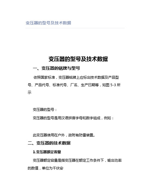
变压器的型号及技术数据变压器的型号及技术数据一、变压器的铭牌与型号依照国家标准,变压器铭牌上应标出技术数据及产品型号、产品代号、标准代号、厂名、生产曰期等,如图5-3所示变压器的型号:变压器的型号是用汉语拼音字母和数字组成,例如:此变压器使用在户外,故附有防雷装置。
二、变压器的技术数据1.变压器额定容量变压器额定容量是指变压器在额定工作条件下,输出功率的数值,单位为千伏安(kV • A)。
新型变压器额定容量,按R10系列组合,即按照¹⁰√10=1.2589254…,近似取1. 26倍数递增分等。
目前,新系列变压器容量等级为:10kV • A,20kV • A,30kV • A,40kV• A,50kV • A,63kV •A, 80kV •A,100kV •A,125kV •A,160kV • A,200kV • A,250kV • A,315kV • A,400kV • A, 500kV • A,630kV•A,800kV•A,l000kV • A,1250kV • A,1600kV • A,2000kV • A,2500kV•A,3150kV • A,4000kV • A,5000kV •A,6300kV•A,8000kV • A,l0000kV•A等。
旧制变压器额定容量是按R8系列组合,即按⁸√10= 1.35倍数递增分等。
其变压器容量包括:50kV •A,75kV•A,100kV• A,135kV • A,180kV •A,240kV•A,320kV•A,420kV • A,560kV •A,750kV• A,1000kV• A,1850kV• A,1800kV •A,2400kV•A,3200kV•A,4200kV• A, 5600kV• A,7500kV • A,l0000kV • A 等。
2.额定频率我国规定交流电额定频率为50Hz。
3.额定电压额定电压是指变压器在空载状态时,变压器一、二次绕组的标称电压,在变压器高压侧有抽头,两分头之间电压差以额定电压百分比表示,容量为6300kV • A及以下的变压器,高压绕组的调压范围为±5%,而容量为8000kV•A及以上和电压为35kV及以上无载调压的变压器,调压范围为2 x 2. 5%,有载调压变压器的调压范围,3x2.5%。
0GJB9001B版质量手册140308

深圳市金凯进光电仪器有限公司文件类别:一级文件名称:质量手册生效日期:2013年5月8日发行编号: / 受控标识:质量手册文件编号:Aa-1-02-A1编制熊志审核皮志雄批准熊敏发放日期 2013-05-82013—05—8发布 2013—06—1实施0.1质量手册目录01质量手册目录 (1)02质量手册批准书 (3)03任命书 (4)04公司概况 (5)1质量手册说明 (7)2 组织机构 (9)3 质量管理体系活动职责分配 (11)4 质量管理体系 (14)4.1 总要求 (14)4.2 文件要求 (16)4.2.1总则…………………………………………………………………………………………………4.2.2质量手册……………………………………………………………………………………………4.2.3文件控制 (19)4.2.4记录控制 (24)5 管理职责 (27)5.1 管理承诺 (27)5.2 以顾客为关注焦点 (27)5.3 质量方针 (28)5.4 质量策划 (29)5.4.1质量目标………………………………………………………………………………………………5.4.2质量管理体系策划……………………………………………………………………………………5.5 职责、权限和沟通 (30)5.5.1职责和权限…………………………………………………………………………………………5.5.2管理者代表…………………………………………………………………………………………5.5.3内部沟通……………………………………………………………………………………………5.6 管理评审 (37)5.6.1总则……………………………………………………………………………………………………5.6.2评审输入………………………………………………………………………………………………5.6.3评审输出………………………………………………………………………………………………6.1 资源提供 (40)6.2 人力资源 (41)6.2.1总则…………………………………………………………………………………………………6.2.2能力、培训和意识…………………………………………………………………………………6.3 基础设施 (45)6.4 工作环境 (48)6.5 质量信息 (50)7 产品实现 (54)7.1 产品实现的策划 (55)7.2 与顾客有关过程( (59)7.2.1与产品有关的要求确定…………………………………………………………………………………7.2.2与产品有关要求的评审…………………………………………………………………………………7.2.3顾客沟通…………………………………………………………………………………………………7.3 设计和开发 (64)7.3.1设计和开发策划…………………………………………………………………………………………7.3.2设计和开发输入…………………………………………………………………………………………7.3.3设计和开发输出…………………………………………………………………………………………7.3.4 设计和开发评审 (71)7.3.5设计和开发验证…………………………………………………………………………………………7.3.6设计和开发确认…………………………………………………………………………………………7.3.7设计和开发更改…………………………………………………………………………………………7.3.8 新产品试制 (74)7.3.9试验控制…………………………………………………………………………………………………7.4 采购 (77)7.4.1采购过程…………………………………………………………………………………………………7.4.2采购信息…………………………………………………………………………………………………7.4.3采购产品的验证…………………………………………………………………………………………7.4.4采购新设计和开发的产品..........................................................................................7.5 生产和服务提供 (81)7.5.1生产服务提供的控制……………………………………………………………………………………7.5.2生产和服务提供过程的确认……………………………………………………………………………7.5.3标识和可追溯性…………………………………………………………………………………………7.5.4顾客财产…………………………………………………………………………………………………7.5.6 关键过程 (88)7.5.7交付………………………………………………………………………………………………………7.5.8交付后的活动…………………………………………………………………………………………7.6 监视和测量设备 (91)7.7 技术状态管理 (94)8 测量、分析和改进 (97)8.1 总则 (97)8.2 监视和测量………………………………………………………………………………………………8.2.1 顾客满意 (99)8.2.2 内部审核 (103)8.2.3 过程监视和测量 (107)8.2.4 产品监视和测量 (109)8.3 不合格品 (113)8.4 数据分析 (116)8.5 改进………………………………………………………………………………………………………8.5.1 持续改进 (120)8.5.2 纠正措施 (123)8.5.3预防措施 (125)8.5.4不良成本 (125)图1质量管理体系模式图(5.4.1) (131)图2产品实现过程图(7.1) (132)图3合同评审流程图(7.2) (133)图4生产工艺流程图 (134)表1 程序文件目录 (135)表2 质量手册会签表 (136)表3质量手册更改记录 (137)0.2《质量手册》批准书深圳市金凯进光电仪器有限公司质管办,依据GB/T19001—2008《质量管理体系—要求》(ISO9001:2008,IDT) 和GJB9001B—2009标准要求和国家颁布的法律法规,结合公司实际,编制完成了《质量手册(2013版/E版)》,通过审订正式批准颁布。
3680系列精密潜入杆电阻器产品说明书
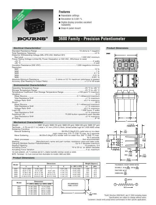
*RoHS Directive 2002/95/EC Jan 27 2003 including AnnexSpecifications are subject to change without notice.Customers should verify actual device performance in their specific applications.Electrical Characteristics 1Standard Resistance Range .............................................................................10 ohms to 1 megohm Total Resistance Tolerance...........................................................................................................±3 %Dielectric Withstanding Voltage (MIL-STD-202, Method 301)Sea Level..........................................................................................................1,000 VAC minimum Power Rating (Voltage Limited By Power Dissipation or 500 VAC, Whichever is Less)+25 °C ...................................................................................................................................2 watts +85 °C......................................................................................................................................0 watt Insulation Resistance (500 VDC)..................................................................1,000 megohms minimum Resolution3681..........................................................................................................................................10 %3682............................................................................................................................................1 %3683.........................................................................................................................................0.1 %3684.......................................................................................................................................0.01 %3685.....................................................................................................................................0.001 %Absolute Minimum Resistance...............................3 ohms or 0.2 % maximum (whichever is greater)Accuracy (Dial Reading to Output Ratio)....................................................................±1.0 % full scaleEnvironmental Characteristics1Operating Temperature Range ...................................................................................-25 °C to +85 °C Storage Temperature Range.......................................................................................-25 °C to +85 °C Temperature Coefficient Over Storage Temperature Range...........................±100 ppm/°C maximum Vibration.........................................................................................................................................10 G Wiper Bounce...........................................................................................0.1 millisecond maximum Total Resistance Shift..............................................................................................±1 % maximum Voltage Ratio Shift................................................................................................±0.2 % maximum Shock.............................................................................................................................................50 G Wiper Bounce...........................................................................................0.1 millisecond maximum Total Resistance Shift..............................................................................................±1 % maximum Voltage Ratio Shift................................................................................................±0.2 % maximum Load Life...............................................................................................................1,000 hours, 2 watts Total Resistance Shift..............................................................................................±2 % maximum Rotational Life.........................................................................75,000 button operations each decade Total Resistance Shift..............................................................................................±2 % maximum IP Rating........................................................................................................................................IP 40Mechanical Characteristics 1Weight....................................3681 (9 gm); 3682 (16 gm); 3683 (23 gm); 3684 (30 gm); 3685 (37 gm)T erminals.....2.79 mm (0.11 in.) wide x .41 mm (.016 in.) thick, tinned solder lugs for 3 #20 AWG wires Soldering ConditionManual Soldering..........................................................96.5Sn/3.0Ag/0.5Cu solid wire or no-cleanrosin cored wire; 370 °C (700 °F) max. for 3 secondsWave Soldering....................96.5Sn/3.0Ag/0.5Cu solder with no-clean flux; 260 °C (500 °F) max.for 5 secondsWash processes..................................................................................................Not recommended Marking...............................Manufacturer’s name and part number, resistance value and date code.Ganging (Multiple Section Potentiometers)...............................................Up to 5 decades maximum Readout Marking........................................................................................................10 positions, 0-9Actuating Force...................................................................................19 to 29 oz. on detent decades Actuating Force Variation..............................................................................................4 oz. maximum1At room ambient: +25 °C nominal and 50 % relative humidity nominal, except as noted.NOTE: Terminals 1 & 3 are reversed from illustration for models 3682 and 3684.3680INCR.Product DimensionsDimensionsWeight (Approx.)Model a b c d e –.381 (–.015)oz.gms.368116.51 (.650)14.99 (.590)—9.91 (.39) 4.19 (.165).3369.5368226.67 (1.05)25.15 (.99)10.67 (.42)11.94 (.47)8.38 (.330).57616.5368337.08 (1.46)35.31 (1.39)18.54 (.73)11.94 (.47) 4.19 (.165).82423.5368447.50 (1.87)45.47 (1.79)30.73 (1.21)11.94 (.47)8.38 (.330) 1.07230.5368557.66 (2.270)55.63 (2.190)39.12 (1.540)11.94 (.47)4.19 (.165)1.32037.5DimensionsModel f –.010 (–.254)g –.010 (–.254)368121.08 (.830)15.75 (.620)368221.08 (.830)25.91 (1.020)368321.08 (.830)36.07 (1.420)368421.08 (.830)46.23 (1.820)368521.08 (.830)56.39 (2.220)*Ro H S C O M P L I A N T V E R S I O N S A V A I L A B L ESpecifications are subject to change without notice.Customers should verify actual device performance in their specific applications.Recommended Part NumbersBOLDFACE LISTINGS ARE IN STOCK AND READILY AVAILABLE THROUGH DISTRIBUTION.FOR OTHER OPTIONS CONSULT FACTORY.RoHS IDENTIFIER:L =COMPLIANTBLANK =NON-COMPLIANTREV. 05/07。
Multi9断路器2003
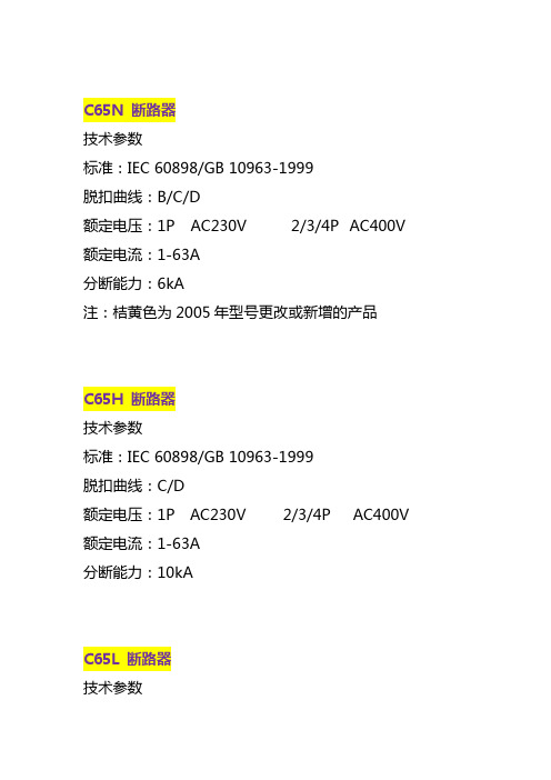
C65N 断路器技术参数标准:IEC 60898/GB 10963-1999脱扣曲线:B/C/D额定电压:1P AC230V 2/3/4P AC400V 额定电流:1-63A分断能力:6kA注:桔黄色为2005年型号更改或新增的产品C65H 断路器技术参数标准:IEC 60898/GB 10963-1999脱扣曲线:C/D额定电压:1P AC230V 2/3/4P AC400V 额定电流:1-63A分断能力:10kAC65L 断路器技术参数标准:IEC 60947-2/GB 14048.2脱扣曲线:C/D额定电压:1P AC230V 2/3/4P AC400V额定电流:1-63A分断能力:15kAC65H-DC 直流断路器技术参数脱扣曲线:B/C额定电压:1P AC230V 2/3/4P AC400V额定电流:1-63A分断能力:10kAVigi C65 漏电保护附件技术参数标准:IEC 61009/GB 16917额定电压:AC 230/400V额定电流:ELE In≤40A, In≤63A ELM In≤32A, In≤63A额定剩余动作电流:30mA/AC类说明Vigi C65 ELE 漏电保护附件Vigi C65 1P+N 40A ELEVigi C65 1P+N 63A ELEVigi C65 2P 40A ELEVigi C65 2P 63A ELEVigi C65 3P 40A ELEVigi C65 3P 63A ELEVigi C65 4P 40A ELEVigi C65 4P 63A ELEVigi C65 ELE G 具有过压保护的漏电附件Vigi C65 G 1P+N 40A ELEVigi C65 G 1P+N 63A ELEVigi C65 G 2P 40A ELEVigi C65 G 2P 63A ELEVigi C65 ELM 漏电保护附件Vigi C65 2P 32A ELMVigi C65 2P 63A ELMVigi C65 3P 32A ELMVigi C65 3P 63A ELMVigi C65 4P 32A ELMVigi C65 4P 63A ELMNC100H / NC125H 断路器技术参数标准: IEC 60947-2/GB 14048-2脱扣曲线:C/D类型额定电压及分断能力:1P 2/3/4P 额定电流:63-125A说明NC100H 断路器NC100H 1P C63ANC100H 1P C80ANC100H 1P C100ANC100H 2P C63ANC100H 2P C80ANC100H 2P C100ANC100H 3P C63ANC100H 3P C80ANC100H 3P C100ANC100H 4P C63A NC100H 4P C80A NC100H 4P C100A NC100H 1P D63A NC100H 1P D80A NC100H 1P D100A NC100H 2P D63A NC100H 2P D80A NC100H 2P D100A NC100H 3P D63A NC100H 3P D80A NC100H 3P D100A NC100H 4P D63A NC100H 4P D80A NC100H 4P D100A NC125H 断路器NC125H 1P C125A NC125H 2P C125A NC125H 3P C125A NC125H 4P C125ANC100LS 断路器技术参数标准: IEC 60947-2/GB 14048-2脱扣曲线:C/D类型额定电压及分断能力:1P 2/3/4P额定电流:10-63AVigi NC100 电磁式漏电保护附件技术参数标准:IEC 61009/GB 16917额定电压:AC 220/415V额定电流: In≤100A额定剩余动作电流:30/300/300 s/500/1000 s mA/AC类说明Vigi NC100 2P 30mAVigi NC100 2P 300mAVigi NC100 2P 500mAVigi NC100 2P 300mA SVigi NC100 2P 1000mA SVigi NC100 3P 30mAVigi NC100 3P 300mAVigi NC100 3P 500mAVigi NC100 3P 300mA SVigi NC100 3P 1000mA SVigi NC100 4P 30mAVigi NC100 4P 300mAVigi NC100 4P 500mAVigi NC100 4P 300mA SVigi NC100 4P 1000mA SC120N 断路器技术参数标准:IEC 60898/GB 10963-1999IEC 60947-2/GB 14048-2脱扣曲线:C/D类型额定电压及分断能力:1P 2/3/4P 额定电流:125A电气附件与辅助装置说明C65/C120/DPN K2/DPN N 电气附件OF (1NO-NC)SDOF+SD /OFMX+OF 220…415V AC 110…130V DC MX+OF 48…130V AC 48V DCMX+OF 24V AC 24V DCMX+0F 12V AC 12V DCMN 220…240V ACMN 48V ACMN 48V DCMN S 220…240V ACNC100/NC125/C32H-DC 电气附件OF(1NO-NC)SDMX+OF 220…415V ACMX+OF 110... 220V AC 110…125V DC MX+OF 24... 48V AC/DCMN 220... 240V AC/DCMN S 220...240V AC/DCC65/C120 远程控制附件说明DPN 3ADPN 6ADPN 10ADPN 16ADPN 20ADPNK2 10ADPNK2 16ADPNK2 20ADPNK2 25ADPNK2 32ADPNK2 40ADPN N C25 6KADPN N C32 6KADPN N C40 6KADPN 系列漏电保护断路器技术参数标准:IEC 61009/GB 16917脱扣曲线:C额定电压:AC 230V额定电流:DPN vigi (G) 6-20ADPN N vigi 6-40A分断能力:DPN vigi (G) 4.5kADPN N vigi 6kA额定剩余动作电流:30mA/AC类说明DPN vigi 漏电保护断路器DPN vigi 6ADPN vigi 10ADPN vigi 16ADPN vigi 20ADPN vigi G 具有过压功能漏电保护断路器DPN vigi G 6ADPN vigi G 10ADPN vigi G 16ADPN vigi G 20ADPN N vigi 漏电保护断路器DPN N vigi C6A 30mADPN N vigi C10A 30mADPN N vigi C16A 30mADPN N vigi C20A 30mADPN N vigi C25A 30mADPN N vigi C32A 30mADPN N vigi C40A 30mA隔离开关及漏电开关技术参数标准:IEC 61008/GB 16916额定电压:AC 230V额定电流:ID 16, 25A额定剩余动作电流:ID 10mA/AC类说明INT 隔离开关INT 1P 32AINT 2P 32AINT 3P 32AINT 4P 32AINT 1P 63AINT 2P 63AINT 3P 63AINT 4P 63AINT 1P 100AINT 2P 100AINT 3P 100AINT 4P 100AID 漏电开关ID 漏电开关 25A 10mA ID 漏电开关 16A 10mA。
最全钢芯铝绞线技术参数表【范本模板】
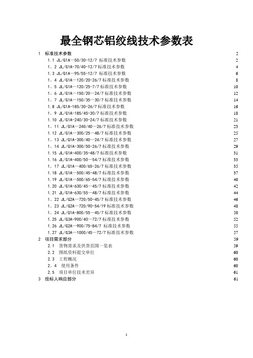
最全钢芯铝绞线技术参数表1 标准技术参数 (2)1.1 JL/G1A—50/30-12/7 标准技术参数 (2)1。
2 JL/G1A-70/40-12/7标准技术参数 (4)1.3 JL/G1A—95/55-12/7 标准技术参数 (6)1。
4 JL/G1A—120/20-26/7标准技术参数 (8)1。
5 JL/G1A—120/25-7/7标准技术参数 (10)1。
6 JL/G1A—150/20—24/7标准技术参数 (12)1。
7 JL/G1A—150/35—30/7标准技术参数 (14)1.8 JL/G1A-185/30-26/7标准技术参数 (16)1。
9 JL/G1A-185/45-30/7标准技术参数 (18)1.10 JL/G1A-240/30-24/7标准技术参数 (21)1。
11 JL/G1A—240/40—26/7标准技术参数 (23)1.12 JL/G1A—300/25—48/7标准技术参数 (25)1。
13 JL/G1A-300/40—24/7标准技术参数 (27)1。
14 JL/G1A-300/50-26/7标准技术参数 (29)1.15 JL/G1A-400/35-48/7标准技术参数 (31)1.16 JL/G1A-400/50—54/7标准技术参数 (33)1。
17 JL/G1A—400/65-26/7标准技术参数 (35)1.18 JL/G1A—500/45-48/7标准技术参数 (37)1.19 JL/G1A—500/65-54/7标准技术参数 (40)1.20 JL/G1A-630/45—45/7标准技术参数 (42)1.21 JL/G1A-630/55—48/7标准技术参数 (44)1。
22 JL/G2A—720/50-45/7标准技术参数 (46)1。
23 JL/G2A—720/90-54/19标准技术参数 (48)1。
24 JL/G1A-800/55—45/7标准技术参数 (50)1.25 JL/G3A-900/40—72/7标准技术参数 (52)1.26 JL/G2A—900/75-84/7 标准技术参数 (55)1.27 JL/G3A—1000/45—72/7标准技术参数 (57)2 项目需求部分 (59)2.1货物需求及供货范围一览表 (59)2.2图纸资料提交单位 (60)2.3工程概况 (60)2。
SENTRON 三极塑胶保护电路断屉 3VA1 IEC 型号说明书
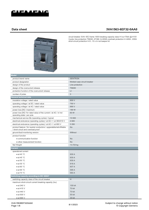
Model product brand name product designation design of the product design of the overcurrent release protection function of the overcurrent release number of poles
General technical data insulation voltage / rated value operating voltage / at DC / rated value operating voltage / at AC / rated value power loss [W] / maximum power loss [W] / for rated value of the current / at AC / in hot operating state / per pole mechanical service life (operating cycles) / typical electrical endurance (operating cycles) / at AC-1 / at 380/415 V electrical endurance (operating cycles) / at AC-1 / at 690 V product feature / for neutral conductors / upgradable/retrofittable / short-circuit and overload proof ground-fault monitoring version product function ● communication function ● other measurement function Net Weight
熔断器资料

Dimensions
A
B
C
D
E
154
64
48
65
95
单件重量(g)
Unit Weight
250
630
尺寸(MM)
Dimensions
A
B
C
φd
E
F
G
H
257
228
61
10.5
35
105
25
30
单件重量(g)
Unit Weight
1030/1310
型号
TYPE
NT4,RT17底座
额定电流(A)
Current Rating
1000
尺寸(MM)
Dimensions
A
B
C
φd
E
F
G
H
300
264
71
8.5
34
137
24
30
单件重量(g)
Unit Weight
2520
NTA00熔断体Fuse link
NTA1熔断体Fuse link
NTA2熔断体Fuse link
NTA3熔断体Fuse link
型号
TYPE
NTA00
额定电流(A)
Current Rating
4、6、10、20、25、32、40、50、63、80、100、125、160
额定电流(A)
Current Rating
2,4,6,10,16,20,25,32,36,40,50,63,80,100
尺寸(MM)
Dimensions
A
B
C
D
1KV聚氯乙烯绝缘电力电缆样本

本产品按 GB/T12706—2008《额定电压 1kV 到 35kV 挤包绝缘电力电缆及附件》标准生 产 0.6/1kV 聚氯乙烯绝缘电力电缆,同时还可根据用户需要按国际电工委员会推荐标准 IEC、英国标准、德国标准及美国标准生产. The product is manufactured according to the standard of GB/T12706—2008 or IEC and BS and DIN and ICEA.
---
VLV22 VLV23
2.5 ~ 400
VV32 VV33
VLV32 VLV33
10 ~ 400
VV VY
---
1.0 ~ 400
---
VLV VLY
4.0 ~ 400
VV22 VV23
---
3+1
1.0 ~ 400
---
VLV22 VLV23
4.0 ~ 400
VV32 VV33
VLV32 VLV33
1.0 ~ 800 2.5 ~ 800 10 ~ 800
VV VY
---
1.0 ~ 300
---
VLV VLY
2.5 ~ 300
VV22 VV23
---
2
1.5 ~ 300
--
VLV22 3
2.5 ~ 300
VV32 VV33
VLV32 VLV33
10 ~ 300
VV VY
---
1.0 ~ 400
Aluminum conductor PVC insulated steel tape armored PVC unable to bear large pulling force.
安徽诺基尔电气有限公司产品说明书

145% # )ApprovalsFM and CSA approved for IS - Class I, Div. 1 & 2, Groups A, B, C, and D; Class II, Groups E, F , and G.Approved for NIFW - Class I, Div. 2FM (US & Canada) approved under 3037789 & 3037789C CSA certified under File 13976, Class 3228-01 (Certificate 1099243)ATEX Approved for:II 1 G Ex ia IIC T6 Ga under FM10ATEX0015X IECEx Approved for:Ex ia IIC T6 Ga under IECExFMG10.0008X Meets applicable CE directives.Refer to Engineering Section for details.Entity ParametersV max = 32 VDC C i = 0 nF I max = 500 mA L i = 0 mHP i = 1.5 WNominal voltage before the barrier – 24VDC +/- 10%.IMPORTANT: Maximum allowable "Off" state leakage current or supervisory current is 4.0 mA.Example:With Aluminum Junction Box – JPIS8314B300With 316L Stainless Steel Junction Box – JSIS8314B300With Conduit – IS8314B300With Quick Disconnect – ISVT8314B300With DIN Connection – ISSC8314B300 (Connector not included)Ordering InformationFeatures•Available in 4 different coil terminations • H Class coil construction• Designed solely for installation in intrinsically safe or NIFW areas, with properly approved and sized limiting barriers• Compatible with supervisory current applications • Mountable in any positionElectricalR coil - The r e s i s ta n ce of the s ole n oid coil atT ambie n t i n deg r ee s C- Loop cu rr en t in t he ci r cui t , which may becalcula t ed as follows:= 320 ohm s x (T ambie n t + 234)254V supply(R coil + R loop + R ba rr ie r )=I loop I loop - Re s i s ta n ce of the lead wi r e sR loop- I n te rn al r e s i s ta n ce of the ba rr ie r R ba rr ie r - Su pply voltageV su pply Whe r e:R coil This current must always be greater than or equal to 0.030 amps for proper operation of the solenoid valve.2/2•3/2•4/25/2•5/3SERIES146Specifications (English units)ImportantThese solenoid valves are intended for use on clean dry air or inert gas, filtered to 40 micrometres or bet-ter. The dew point of the media should be at least 10°C (18° F) below the minimum temperature to which any portion of the clean air/inert gas system could be exposed to prevent freezing. If lubricated air is used,the lubricants must be compatible with N itrile elas-tomers. Diester oils may cause operational problems.Instrument air in compliance with ANSI/ISA Standard 7.0.01-1996 exceeds the above requirements and is,therefore, an acceptable media for these valves.*Does not include JPIS8316B334; Includes JPIS8316B374. Note : 8553 not available in brassSpecifications (English units)147148Specifications (Metric units)149150Dimensions: inches (mm)M12 x 1 THREAD3.36 [85]2.36 [60].47 [12]1/2 NPT4.46 [113]3.47 [88]3.13 [79]2.04 [52]1.95 [50]3.58 [91]1.95 [50]1.95 [50]1.89 [48]2.58 [66]1.54 [39]1.54 [39]1.54 [39]1.54 [39]2.23 [57]1.68 [43]1.95 [50]1/2 NPTJUNCTION BOXMULTIPINCONDUITDINS P E C I A L S E R V I C E P I L O T151Dimensions: inches (mm)Dimensions: inches (mm)152S P E C I A L S E R V I C E P I L O T153Dimensions: inches (mm)Dimensions: inches (mm)154S P E C I A L S E R V I C E P I L O TDimensions: inches (mm)Dimensions: inches (mm)S P E C I A L S E R V I C E P I L O TDimensions: inches (mm)Dimensions: inches (mm)。
产品管理-法国溯高美低压产品介绍
自动转换开关 ATYS
ATyS 3s
ATyS 3e
电动转换开关
单电源
ATyS 6e
ATyS 6m
自动转换开关
双电源供电
集成控制器 可选模块
测量+显示
可连接监控界面
ATyS C20/30/40
独立控制器
附件
ATYS D10/20
SWITCHING RANGE GB 10/2005
SWITCHING RANGE GB 10/2005
ATyS 3 和 ATyS 6 区别
手动转换开关 +电动模块=ATyS 3S +控制器=ATyS 6
手动转换开关
MTS
GB14048.112008
ATyS 3 RTS
GB14048.112008
SWITCHING RANGE GB 10/2005
ATyS 6:
ATyS 6e : 125 – 3200A,3P/4P 12个电流等级 ATyS 6m: 125 – 3200A,3P/4P 12个电流等级
SWITCHING RANGE GB 10/2005
其它功能
应急手动操作 0位置锁定 (可设置位置I & II) 自动/手动选择 ( e & m 型采用钥匙 ) 电动操作 位置指示辅助触点
负荷隔离开关
LOAD BREAK SWITCHES
SWITCHING RANGE GB 10/2005
负荷隔离开关
应用
发电机输出
母联
进线开关
遥控脱扣进线开关
就地断开 和/或 紧急断电
机器控制
低温塑料导线,20AWG(10x30)锡胶腔导线,PVC胶胶腔,CSA类型TR-64 TRSR-64

PVC - Polyvinyl Chloride 0.067 in
0.016 in
0.015 in
Color Chart 2 Number 6
Electrical Characteristics
High Frequency (Nominal/Typical) Nom. Insertion Loss 6.1 dB/100m 6.1 dB/100m 6.1 dB/100m
All sales of Belden products are subject to Belden's standard terms and conditions of sale.
Belden believes this product to be in compliance with all applicable environmental programs as listed in the data sheet. The information provided is correct to the best of Belden's knowledge, information and belief at the date of its publication. This information is designed only as a general guide for the safe handling, storage, and any other operation of the product itself or the one that it becomes a part of. The Product Disclosure is not to be considered a warranty or quality specification. Regulatory information is for guidance purposes only. Product users are responsible for determining the applicability of legislation and regulations based on their individual usage of the product.
京信天线资料!230
京信天线资料!230(电信集采版)说明:本册为中国电信集采类产品单页资料,并仅限用于电信客户的集采产品订货。
主要根据《2010年中国电信基站天线及室分天线集采》制定。
天馈事业部天线国内市场部2010年10月目录一、全向天线 ..................................................................... .. (1)型号:OOA-360V11A ................................................................ ................................................................ 1 二、定向单极化天线 ..................................................................... .. (2)型号:ODP-065V17A ................................................................ . (2)型号:ODP-065V18A ................................................................ . (3)型号:ODP-090V17A ................................................................ ................................................................ 4 三、定向双极化天线 ..................................................................... .. (5)型号:ODP-032R18A................................................................. . (5)型号:ODP-032R21A................................................................. . (6)型号:ODP-065R15A................................................................. . (7)型号:ODP-065R17A................................................................. . (8)型号:ODP-065R18A................................................................. . (9)型号:ODP-090R17A................................................................. .............................................................. 10 四、双极化电调天线 ..................................................................... (11)型号:ODV-032R18A ................................................................ .. (11)型号:ODV-032R20A ................................................................ .. (12)型号:ODV-065R15A ................................................................ .. (13)型号:ODV-065R17A ................................................................ .. (14)型号:ODV-065R18A ................................................................ .. (15)型号:ODV-090R17A ................................................................ .. (16)天线产品技术单页一、全向天线型号:OOA-360V11A产品描述:CDMA800/360?11dBi全向天线工作频率( MHz) 820-880 天线增益(dBi) 11?1极化方式垂直极化水平面波瓣宽度(?) 360 垂直面波瓣宽度(?) 6.5?2 方向图不圆度(dB) ?1电下倾角(?) 3下倾精度(?) ?1驻波比 ?1.4 三阶交调(dBm) ?-107阻抗(Ω) 50 功率容量(W) 500 天线尺寸(mm) 3510×Ф52重量(Kg) 12.5接头类型 7/16阴头环境温度(?C) -55,+70工作风速110km/h,极限风速抗风能力 200km/h雷电保护直接接地820,880 MHz方向图水平面垂直面1天线产品技术单页二、定向单极化天线型号:ODP-065V17A产品描述:CDMA800/65?17dBi单极化非电调天线工作频率( MHz) 820-880 天线增益(dBi) 17?1极化方式垂直极化水平面波瓣宽度(?) 65?5 垂直面波瓣宽度(?) 9?2 前后比(dB) ?28 第一上旁瓣抑制(dB) ?-15下倾精度(?) ?1驻波比 ?1.4 三阶交调(dBm) ?-107电下倾角(?) 0阻抗(Ω) 50 功率容量(W) 500 天线尺寸(mm) 1935×265×141重量(Kg) 11机械倾角(?) 0-12接头类型 7/16 Din阴头环境温度(?C) -55,+70工作风速110km/h,极限风速抗风能力 200km/h雷电保护直接接地 820,880 MHz方向图水平面垂直面2天线产品技术单页型号:ODP-065V18A产品描述:CDMA800/65?18dBi单极化非电调天线工作频率( MHz) 820-880 天线增益(dBi) 18?1极化方式垂直极化水平面波瓣宽度(?) 65?5 垂直面波瓣宽度(?) 7?2 前后比(dB) ?28 第一上旁瓣抑制(dB) ?-15下倾精度(?) ?1驻波比 ?1.4 三阶交调(dBm) ?-107电下倾角(?) 0/3阻抗(Ω) 50 功率容量(W) 500 天线尺寸(mm) 2615×265×141重量(Kg) 16.0机械倾角(?) 0-8接头类型 7/16 Din阴头环境温度(?C) -55,+70 工作风速110km/h,极限风速抗风能力 200km/h 雷电保护直接接地820,880MHz方向图水平面垂直面3天线产品技术单页型号:ODP-090V17A产品描述: CDMA800/90?17dBi单极化非电调天线工作频率( MHz) 820-880 天线增益(dBi) 16.5?1极化方式垂直极化水平面波瓣宽度(?) 90?8 垂直面波瓣宽度(?) 7?2 第一上旁瓣抑制(dB) ?-15前后比(dB) ?25下倾精度(?) ?1驻波比 ?1.4 三阶交调(dBm) ?-107电下倾角(?) 0/3/6阻抗(Ω) 50功率容量(W) 500 天线尺寸(mm) 2615×265×141重量(Kg) 15机械倾角(?) 0-8接头类型 7/16 Din阴头环境温度(?C) -55,+70工作风速110km/h,极限风速抗风能力 200km/h雷电保护直接接地820,880 MHz方向图水平面垂直面4天线产品技术单页三、定向双极化天线型号:ODP-032R18A描述:CDMA800/32?18dBi双极化定向天线工作频率( MHz) 820-880 天线增益(dBi) 18?1极化方式 ?45?交叉极化水平面波瓣宽度(?) 32?4 垂直面波瓣宽度(?) 14?2 前后比(dB) ?30 第一上旁瓣抑制(dB) ?-15轴向:?15 交叉极化比(dB) ?15?内:?10下倾精度(?) ?1驻波比 ?1.4隔离度(dB) ?30 三阶交调(dBm) ?-107电下倾角(?) 0/3阻抗(Ω) 50 功率容量(W) 500 天线尺寸(mm) 1315×552×141重量(Kg) 20机械倾角(?) 0-16接头类型 7/16阴头环境温度(?C) -55,+70抗风能力工作风速110km/h,极限风速200km/h雷电保护直流接地 820,880 MHz方向图水平面垂直面5天线产品技术单页型号:ODP-032R21A描述:CDMA800/32?21dBi双极化定向天线工作频率( MHz) 820-880 天线增益(dBi) 20?1极化方式 ?45?交叉极化水平面波瓣宽度(?) 32?4 垂直面波瓣宽度(?) 7?2 前后比(dB) ?30 第一上旁瓣抑制(dB) ?-15轴向:?15 交叉极化比(dB) ?15?内:?10下倾精度(?) ?1驻波比 ?1.4隔离度(dB) ?30 三阶交调(dBm) ?-107电下倾角(?) 0/3阻抗(Ω) 50 功率容量(W) 500 天线尺寸(mm) 2615×552×141重量(Kg) 37.5机械倾角(?) 0-8接头类型 7/16阴头环境温度(?C) -55,+70抗风能力工作风速110km/h,极限风速200km/h 雷电保护直流接地820,880 MHz方向图水平面垂直面6天线产品技术单页型号:ODP-065R15A描述:CDMA800/65?15dBi双极化定向天线工作频率( MHz) 820-880 天线增益(dBi) 15?1极化方式 ?45?交叉极化水平面波瓣宽度(?) 65?5 垂直面波瓣宽度(?) 14?2 前后比(dB) ?25 第一上旁瓣抑制(dB) ?-15轴向:?15 交叉极化比(dB) ?60?内:?10下倾精度(?) ?1驻波比 ?1.4隔离度(dB) ?30 三阶交调(dBm) ?-107电下倾角(?) 0/3/6阻抗(Ω) 50 功率容量(W) 500 天线尺寸(mm) 1315×265×141重量(Kg) 9.5机械倾角(?) 0-16接头类型 7/16阴头环境温度(?C) -55,+70工作风速110km/h,极限风速抗风能力 200km/h雷电保护直流接地820,880 MHz方向图水平面垂直面7天线产品技术单页型号:ODP-065R17A描述:CDMA800/65?17dBi双极化定向天线工作频率( MHz) 820-880 天线增益(dBi) 17?1极化方式 ?45?交叉极化水平面波瓣宽度(?) 65?5 垂直面波瓣宽度(?) 9?2 前后比(dB) ?25 第一上旁瓣抑制(dB) ?-15轴向:?15 交叉极化比(dB) ?60?内:?10下倾精度(?) ?1驻波比 ?1.4隔离度(dB) ?30 三阶交调(dBm) ?-107电下倾角(?) 0/3/6阻抗(Ω) 50 功率容量(W) 500 天线尺寸(mm) 1935×265×141重量(Kg) 13.8机械倾角(?) 0-12接头类型 7/16阴头环境温度(?C) -55,+70抗风能力工作风速110km/h,极限风速200km/h 雷电保护直流接地820,880 MHz方向图水平面垂直面8天线产品技术单页型号:ODP-065R18A描述:CDMA800/65?18dBi双极化定向天线工作频率( MHz) 820-880 天线增益(dBi) 18?1极化方式 ?45?交叉极化水平面波瓣宽度(?) 65?5 垂直面波瓣宽度(?) 7?2 前后比(dB) ?25 第一上旁瓣抑制(dB) ?-15轴向:?15 交叉极化比(dB) ?60?内:?10下倾精度(?) ?1驻波比 ?1.4隔离度(dB) ?30 三阶交调(dBm) ?-107电下倾角(?) 0/3/6阻抗(Ω) 50 功率容量(W) 500 天线尺寸(mm) 2615×265×141重量(Kg) 18.5机械倾角(?) 0-8接头类型 7/16阴头环境温度(?C) -55,+70工作风速110km/h,极限风速抗风能力 200km/h雷电保护直流接地820,880 MHz方向图水平面垂直面9天线产品技术单页型号:ODP-090R17A描述:CDMA800/90?17dBi双极化定向天线工作频率( MHz) 820-880 天线增益(dBi) 16.5?1极化方式 ?45?交叉极化水平面波瓣宽度(?) 90?8 垂直面波瓣宽度(?) 7?2 前后比(dB) ?23 第一上旁瓣抑制(dB) ?-15轴向:?15 交叉极化比(dB) ?60?内:?10下倾精度(?) ?1驻波比 ?1.4隔离度(dB) ?30 三阶交调(dBm) ?-107电下倾角(?) 0/3/6阻抗(Ω) 50 功率容量(W) 500 天线尺寸(mm) 2615×265×141重量(Kg) 31.5机械倾角(?) 0-8接头类型 7/16阴头环境温度(?C) -55,+70工作风速110km/h,极限风速抗风能力 200km/h 雷电保护直流接地820,880 MHz方向图水平面垂直面10天线产品技术单页四、双极化电调天线型号:ODV-032R18A产品描述:CDMA800 / 32?18dBi双极化电调天线工作频率(MHz) 820~880 天线增益(dBi) 17.5?1极化方式 ?45?交叉极化水平面波瓣宽度(?) 32?4 垂直面波瓣宽度(?) 14?2 前后比(dB) ?30 第一上旁瓣抑制(dB) ?-15轴向:?15 交叉极化比(dB) ?15?内:?10下倾精度(?) ?1驻波比 ?1.4隔离度(dB) ?30 三阶交调(dBm) ?-107电下倾角(?) 0-13阻抗(Ω) 50 功率容量(W) 250 天线尺寸(mm) 1415×560×143重量(Kg) 30机械倾角(?) 0-16接头类型 7/16阴头环境温度(?C) -55,+70抗风能力工作风速110km/h,极限风速200km/h雷电保护直接接地820-880 MHz方向图水平面垂直面11天线产品技术单页型号:ODV-032R20A产品描述:CDMA800 / 32?20dBi双极化电调天线工作频率(MHz) 820~880 天线增益(dBi) 19.5?1极化方式 ?45?交叉极化水平面波瓣宽度(?) 32?4 垂直面波瓣宽度(?) 7?2前后比(dB) ?30 第一上旁瓣抑制(dB) ?-15轴向:?15 交叉极化比(dB) ?15?内:?10下倾精度(?) ?1驻波比 ?1.4隔离度(dB) ?30 三阶交调(dBm) ?-107电下倾角(?) 0-10阻抗(Ω) 50 功率容量(W) 250 天线尺寸(mm) 1975×560×143重量(Kg) 41机械倾角(?) 0-12接头类型 7/16阴头环境温度(?C) -55,+70工作风速110km/h,极限风速抗风能力 200km/h 雷电保护直接接地 820-880 MHz方向图水平面垂直面12天线产品技术单页型号:ODV-065R15A产品描述:CDMA800 / 65?15dBi双极化电调天线工作频率(MHz) 820~880 天线增益(dBi) 14.5?1极化方式 ?45?交叉极化水平面波瓣宽度(?) 65?5 垂直面波瓣宽度(?) 14?2 前后比(dB) ?25 第一上旁瓣抑制(dB) ?-15轴向:?15 交叉极化比(dB) ?60?内:?10下倾精度(?) ?1驻波比 ?1.4隔离度(dB) ?30 三阶交调(dBm) ?-107电下倾角(?) 0-14阻抗(Ω) 50 功率容量(W) 250 天线尺寸(mm) 1415×265×141重量(Kg) 12.5机械倾角(?) 0-16接头类型 7/16阴头环境温度(?C) -55,+70抗风能力工作风速110km/h,极限风速200km/h雷电保护直接接地820-880 MHz方向图水平面垂直面13天线产品技术单页型号:ODV-065R17A产品描述:CDMA800 / 65?17dBi双极化电调天线工作频率(MHz) 820~880 天线增益(dBi) 16.5?1极化方式 ?45?交叉极化水平面波瓣宽度(?) 65?5 垂直面波瓣宽度(?) 9?2 前后比(dB) ?25 第一上旁瓣抑制(dB) ?-15轴向:?15 交叉极化比(dB) ?60?内:?10下倾精度(?) ?1驻波比 ?1.4隔离度(dB) ?30 三阶交调(dBm) ?-107电下倾角(?) 0-10阻抗(Ω) 50 功率容量(W) 250 天线尺寸(mm) 2095×265×141重量(Kg) 17.8机械倾角(?) 0-12接头类型 7/16阴头环境温度(?C) -55,+70抗风能力工作风速110km/h,极限风速200km/h雷电保护直接接地820-880 MHz方向图水平面垂直面14天线产品技术单页型号:ODV-065R18A产品描述:CDMA800 / 65?18dBi双极化电调天线工作频率(MHz) 820~880 天线增益(dBi) 17.5?1极化方式 ?45?交叉极化水平面波瓣宽度(?) 65?5 垂直面波瓣宽度(?) 7?2 前后比(dB) ?25 第一上旁瓣抑制(dB) ?-15轴向:?15 交叉极化比(dB) ?60?内:?10下倾精度(?) ?1驻波比 ?1.4隔离度(dB) ?30 三阶交调(dBm) ?-107电下倾角(?) 0-7阻抗(Ω) 50 功率容量(W) 250 天线尺寸(mm) 2615×265×141重量(Kg) 21机械倾角(?) 0-8接头类型 7/16阴头环境温度(?C) -55,+70工作风速110km/h,极限风速抗风能力 200km/h雷电保护直接接地820-880 MHz方向图水平面垂直面15天线产品技术单页型号:ODV-090R17A产品描述:CDMA800 / 90?17dBi双极化电调天线工作频率(MHz) 820-880 天线增益(dBi) 16?1极化方式 ?45?交叉极化水平面波瓣宽度(?) 90?8 垂直面波瓣宽度(?) 7?2 前后比(dB) ?23 第一上旁瓣抑制(dB) ?-15轴向:?15 交叉极化比(dB) ?60?内:?10下倾精度(?) ?1驻波比 ?1.4隔离度(dB) ?30 三阶交调(dBm) ?-107电下倾角(?) 0-7阻抗(Ω) 50 功率容量(W) 250 天线尺寸(mm) 2615×265×141重量(Kg) 27机械倾角(?) 0-8接头类型 7/16阴头环境温度(?C) -55,+70工作风速110km/h,极限风速抗风能力 200km/h雷电保护直接接地820-880 MHz方向图水平面垂直面16天线产品技术单页17天线产品技术单页18。
- 1、下载文档前请自行甄别文档内容的完整性,平台不提供额外的编辑、内容补充、找答案等附加服务。
- 2、"仅部分预览"的文档,不可在线预览部分如存在完整性等问题,可反馈申请退款(可完整预览的文档不适用该条件!)。
- 3、如文档侵犯您的权益,请联系客服反馈,我们会尽快为您处理(人工客服工作时间:9:00-18:30)。
Collector-Emitter Saturation Voltage vs Collector Current
1.2 1 0.8 0.6
25 °C
β = 10
V CE = 1V
25 °C
0.4
- 40 °C
0.2
125 °C
0 0.1
1 10 100 I C - COLLECTOR CURRE NT (mA)
Test Circuit
- 4.0 V 50 V
IC 150 mA 200 mA 500 mA
Rb 314 Ω 157 Ω 94 Ω
RL 330 Ω 167 Ω 100 Ω
- 1 µF 1.0 KΩ RL
Rb
To Sampling Scope Rise Time ≤ 5.0 ns Input Z ≈ 100 kΩ
TAPE and REEL OPTION
FSCINT Label sampl e
FAIRCHIL D S EMICONDUCTOR CORPORATION L OT:
S e e Fig 2 .0 for va rious
HTB:B 10000
Reeli n g Styles
CBVK741B019
QTY:
*Pulse Test: Pulse Width ≤ 300 µs, Duty Cycle ≤ 1.0%
元器件交易网
TN3019A
NPN General Purpose Amplifier
(continued)
Typical Characteristics
VCESAT - COLLECTOR EM ITTE R VOLTAGE (V)
TA = 25°C unless otherwise noted
Parameter
Value
80 140 7.0 1.0 -55 to +150
Units
V V V A °C
Operating and Storage Junction Temperature Range
*These ratings are limiting values above which the serviceability of any semiconductor device may be impaired.
NOTES: 1) These ratings are based on a maximum junction temperature of 150 degrees C. 2) These are steady state limits. The factory should be consulted on applications involving pulsed or low duty cycle operations.
1000
Collector-Cutoff Current vs Ambient Temperature
I CBO - COLLECTOR CURRENT (nA) 10
V CB = 80V
Collector-Base and Emitter-Base Capacitance vs Reverse Bias Voltage
Absolute Maximum Ratings*
Symbol
VCEO VCBO VEBO IC TJ, Tstg Collector-Emitter Voltage Collector-Base Voltage Emitter-Base Voltage Collector Current - Continuous
hFE - TYPICAL PULSED CURRENT GAIN
Typical Pulsed Current Gain vs Collector Current
350 300 250 200 150 100 50 0 0.1 0.3 1 3 10 30 100 300 I C - COLLECTOR CURRENT (mA) 1000
1 0.8 0.6 0.4 0.2 0 0.1 VCE = 1V 1 10 100 I C - COLLECTOR CURRE NT (mA) 1000
- 40°C
25 °C 125°C
25 °C 125 °C
0.4
0 0.1
1 10 100 I C - COLLECTOR CURRE NT (mA)
1000
PD - POWER DISSIPATION (W) 1
Power Dissipation vs Ambient Temperature
TO-226
0.75
800 TIME (ns) 600 400 200 t on 0 10
I B1 = I B2 = I C V CC = 50V 10
0.5
NSID:
PN2222N
SP EC:
FSCINT
SP EC RE V: QA REV:
D/C1:
D9842
B2
Labe l 5 Reels per Int er med iate B ox
Switching Times vs Collector Current
tr 1 10 100 I C - COLLECTOR CURRENT (mA) 500 0 10 IC
tf
ts td 1000
100 500 - COLLECTOR CURRENT (mA)
Turn On and Turn Off Times vs Collector Current
ห้องสมุดไป่ตู้
Electrical Characteristics
Symbol Parameter
TA = 25°C unless otherwise noted
Test Conditions
Min
Max
Units
OFF CHARACTERISTICS
V(BR)CEO V(BR)CBO V(BR)EBO ICBO IEBO Collector-Emitter Breakdown Voltage* Collector-Base Breakdown Voltage Emitter-Base Breakdown Voltage Collector-Cutoff Current Emitter-Cutoff Current IC = 30 mA, IB = 0 IC = 100 µ A, IE = 0 IE = 100 µ A, IC = 0 VCB = 90 V, IE = 0 VCB = 90 V, IE = 0, TA = 150°C VEB = 5.0 V, IC = 0 80 140 7.0 0.01 10 0.01 V V V µA µA µA
1000
β = 10 0.8
- 40 °C
V BEON - BAS E EMITTER ON VOLTAGE (V)
VBESAT - BASE EM ITTE R VOLTAGE (V)
Base-Emitter Saturation Voltage vs Collector Current
Base Emitter ON Voltage vs Collector Current
VCE(sat) VBE(sat)
Collector-Emitter Saturation Voltage Base-Emitter Saturation Voltage
0.2 0.5 1.1
V V V
SMALL SIGNAL CHARACTERISTICS
fT Cobo Cibo hfe rb’Cc NF Current Gain - Bandwidth Product Output Capacitance Input Capacitance Small-Signal Current Gain Collector Base Time Constant Noise Figure IC = 50 mA, VCE = 10 V, f = 20 MHz VCB = 10 V, IE = 0, f = 1.0 MHz VBE = 0.5 V, IC = 0, f = 1.0 MHz IC = 1.0 mA, VCE = 5.0 V, f = 1.0 kHz IE = 10 mA, VCB = 10 V, f = 4.0 MHz IC = 100 mA, VCE = 10 V, RS = 1.0 kΩ, f = 1.0 kHz 80 100 12 60 400 400 4.0 pS dB MHz pF pF
100 f = 1.0 MHz CAPACITANCE (pF) 80 60 40
Ceb
1
20
C cb
0.1 25
50 75 100 T A - AMBIENT TEMPERATURE (° C)
125
0 0.1
1 10 REVERSE BIAS VOLTAGE (V)
50
元器件交易网
ON CHARACTERISTICS
hFE DC Current Gain IC = 0.1 mA, VCE = 10 V IC = 10 mA, VCE = 10 V IC = 150 mA, VCE = 10 V IC=150 mA,VCE=10 V,TA=-55°C IC = 500 mA, VCE = 10 V* IC = 1.0 A, VCE = 10 V* IC = 150 mA, IB = 15 mA IC = 500 mA, IB = 50 mA IC = 10 mA, IB = 15 mA 50 90 100 40 50 15 300
TN3019A
NPN General Purpose Amplifier
(continued)
