An Intelligent System for Aerial Image Retrieval and Classification
arcgis正射影像处理流程
arcgis正射影像处理流程英文回答:Orthorectification of Aerial Imagery in ArcGIS.Step 1: Georeferencing.The first step in orthorectifying aerial imagery is to georeference it to a known coordinate system. This involves assigning real-world coordinates to points in the image. Georeferencing can be done using ground control points (GCPs), which are points with known coordinates on the ground that can be identified in the image.Step 2: Radiometric Correction.Radiometric correction adjusts the brightness and contrast of the image to compensate for variations in lighting conditions during acquisition. This can be done using histogram equalization or other techniques.Step 3: Geometric Correction.Geometric correction removes distortions from the image caused by the camera's perspective and the Earth's curvature. This is done using a digital elevation model (DEM) or other data to correct for the relief displacement and perspective distortions.Step 4: DTM Generation (Optional)。
2021年高考英语的阅读理解专项训练及答案

2021年高考英语的阅读理解专项训练及答案一、高考英语阅读理解专项训练1.阅读理解Smart Kids Festival EventsSmart Kids is a collection of one hundred events scheduled in October. This year, it is experimenting with Pay What You Decide (PWYD). That is, you can decide to pay what you want to or can afford, after you have attended an event. You can pre-book events without paying for a ticket in advance. Here are some of the director's picks.Walk on the Wild SideNot ticketed, FreeJoin storyteller Sarah Law to hear science stories about animals. Along the way you'll meet all sorts of beautiful creatures and discover life cycles and food chains. Best suited to children aged 5-9. Children under 8 must be accompanied by an adult.Introduction to WavesPre-book, PWYDSubjects range from sound waves to gravity waves, and from waves of light to crashing waves on the ocean. Mike Goldsmith explores the fundamental features shared by all waves in the natural world.Science in the FieldNot ticketed, FreeThis storytelling night features a scientist sharing his favourite memories of gathering first-hand data on various field trips. Come along for inspiring and informative stories straight from the scientist's mouth. Join Mark Samuels to find out more in this fun-filled workshop.Festival DinnerPre-book, £25 per personWhether you want to explore more about food, or just fancy a talk over a meal, join us to mark the first science festival in London. Which foods should you eat to trick your brain into thinking that you are full? Find out more from Tom Crawford.(1)In which event can you decide the payment?A. Walk on the Wild SideB. Introduction to WavesC. Science in the FieldD. Festival Dinner(2)Who will talk about experiences of collecting direct data?A.Sarah Law.B.Mike Goldsmith.C.Mark Samuels.D.Tom Crawford.(3)What do the four events have in common?A.Family-based.B.Science-themed.C.Picked by children.D.Filled with adventures.【答案】(1)B(2)C(3)B【解析】【分析】本文是一篇应用文,介绍了Smart Kids收集的在十月份举行的四项以科学会主题的活动,以及各个活动的内容和特色。
科技英语中的名词化现象

3. 名词化在科技英语中的作用
科技英语是有关科学和技术的发展的描述,其目的 是为了使先进的技术能够得到保存和交流。语篇简 洁和语言表述的客观公正性是科技英语语言的主要 特点,而名词化的使用刚好就满足了这两个特性。 此外,名词化的使用对增强科技英语的语篇衔接具 有重要作用,名词化的使用更能明晰的表达科技英 语语篇的逻辑关系。
As we extract the optical path difference with the target spectrum, we can build up an interferogram for each scene element.
提取出目标光谱的光路差异,就能针对每个场景元素 建立干涉图。
For most adaptive optics applications, to place the deformable elements and Wavefront sensors at pupil points within the optical path is advantageous. 对于大多数适应性光学仪器,在光路中的光瞳点放置 可变形元件和波前传感器是非常有利的。
Analysis of the high resolution remote sensing image produced by the CCD camera shows that…
(三)衔接连贯作用
将前句述位中体现过程的动词名词化,作为下句中 的主位或主位的一部分。例如:
FPGA is used for image storage and interface bus control, but the real time use is responsible for logic control as well as auxiliary data transmission.
无人机(英文演讲)
Name:Kenia
ID:17866334
2016.4.21
Hometown:
Leshan giant Buddha
Major: Agricultural Mechanization
self-introduction
Unmanned Aerial Vehicle
Email:mr.fywang@
a long way to go
Advantage
UAV System
Component
propeller
GPS
shaft
sensor
balancer
camera board
support frame
transmission
System theory
Target Area Planning Sampling Points Selection
variable fertilization
deal the data
extract features
பைடு நூலகம்
Variable fertilization
Prescription Map
Actual Applied
Reference
[1] Valera M, Velastin S A.Intelligent distributed survuillance system a review[J].IEEE Proeessing of Vision, Image, and Signal Proeessing, 2005, 152(2):192-204. [2] Veto A, Wiegand T, Sullivan G J.Overview of the stereo and multiview video coding extensions of the H.264/MPEG-4 AVC standard[J].Proceedings of the IEEE, 2011, 99(4):626-642. [3] Hsiao Y M, Lee J F, Chen J S, et al.H.264 video transmissions over wireless networks:Challenges and solutions[J].Computer Communications, 2011, 34(14):16611672. [4] Frauel Y, Quesada O, Bribiesea E.Detection of a polymorphic mesoamerican symbol using a rule-based approach[J].Pattern Recognition, 2006, 39(7):1380-1390. [5] Zeng Qiangyu, He Xiaohai, Lü Rui, et al.Rate control in H.264 wireless video communication system[J].The International Journal for Computation and Mathematics in Electrical and Electronic Engineering, 2010, 29(2):378-387.
苍蝇复眼和航空照相机英语作文
苍蝇复眼和航空照相机英语作文The Compound Eyes of Flies and Aerial Cameras.In the realm of nature and technology, the compound eyes of flies and aerial cameras share remarkable similarities, showcasing the adaptability and ingenuity found in both the organic and mechanical worlds.Compound Eye Structure.A fly's compound eye, a marvel of nature's design, consists of thousands of individual ommatidia, each acting as a miniature lens. These ommatidia are packed densely together, forming a mosaic-like pattern that captures a wide field of view. Each ommatidium has its own light-sensitive cells, enabling the fly to detect movement, shapes, and colors in almost every direction.Aerial Camera Architecture.Aerial cameras, designed to capture aerial imagery from above, typically employ an array of charge-coupled devices (CCDs) or complementary metal-oxide semiconductors (CMOS)as their imaging sensors. These sensors are composed of millions of individual pixels, which are arranged in agrid-like pattern to capture a large field of view. Each pixel, like the ommatidia in a fly's eye, responds to light, allowing the camera to collect images with high resolution and clarity.Field of View and Visual Acuity.Both flies and aerial cameras possess wide fields of view due to their multiple-lens architecture. This panoramic vision allows them to scan their surroundings rapidly, detect potential threats or targets, and navigate their environment effectively. However, despite having a broader field of view, flies generally have poor visual acuity compared to humans. The multifaceted nature of their eyes creates a mosaic-like image, resulting in lower resolution compared to the single-lens camera systems found in aerial cameras.Image Formation and Processing.In a fly's compound eye, the individual ommatidia collect light rays from different angles, forming a composite image in the fly's brain. The fly's visual system processes this image, extracting essential information about the surrounding environment. Similarly, in an aerial camera, the array of CCDs or CMOS sensors captures light rays from the scene below, converting them into electrical signals. These signals are then processed by the camera's electronics to create a digital image that can be stored, transmitted, or analyzed.Motion Detection and Tracking.Flies rely heavily on their compound eyes for detecting and tracking motion. The temporal offset between the signals received by adjacent ommatidia allows them to determine the direction and speed of moving objects. This motion-detection capability is crucial for avoiding predators, finding food, and navigating their surroundings.Aerial cameras, on the other hand, often incorporate advanced algorithms and software to enhance their motion-tracking abilities. They can track specific objects or areas of interest, providing valuable information for surveillance, aerial surveys, and target identification.Night Vision and Color Perception.While flies have limited night vision capabilities, aerial cameras can be equipped with specialized sensorsthat enable them to capture images in low-light conditions. Aerial cameras can also be fitted with filters or multi-spectral sensors to capture images in different wavelengths of the electromagnetic spectrum, providing valuable information for specific applications such as agriculture, forestry, and environmental monitoring.Evolution and Adaptation.The compound eyes of flies are a testament to the extraordinary adaptations that have evolved over millions of years. Through natural selection, these eyes have beenoptimized for a fly's specific ecological niche. Aerial cameras, on the other hand, are the result of human ingenuity and technological advancements. They have been designed to meet specific operational requirements for aerial photography, surveillance, and mapping.Conclusion.The compound eyes of flies and aerial cameras exhibit remarkable parallels in their structure, function, and applications. Both systems leverage the principles of multiple-lens architecture to achieve wide fields of view and capture imagery from their respective vantage points. While flies have evolved these structures through natural selection, aerial cameras have been developed by humans through engineering and innovation. The study of these systems not only provides insights into the incredible diversity of nature but also highlights the ingenuity and problem-solving capabilities of human technology.。
微型空中飞行器系统(MAV)的自动室内飞行的说明书

Quadrotor Using Minimal Sensing For AutonomousIndoor FlightJames F.Roberts*,Timothy S.Stirling†,Jean-Christophe Zufferey‡and Dario Floreano§Ecole Polytechnique Fédérale de Lausanne(EPFL),Lausanne,1015,Switzerland Abstract—This paper presents a Miniature Aerial Vehicle(MAV)capable of hands-off autonomous operation within indoor environments.Our prototype is a Quadrotorweighing approximately600g,with a diameter of550mm,which carries the necessaryelectronics for stability control,altitude control,collision avoidance and anti-driftcontrol.This MAV is equipped with three rate gyroscopes,three accelerometers,oneultrasonic sensor,four infrared sensors,a high-speed motor controller and a flightcomputer.Autonomous flight tests have been carried out in a7x6-m room.I.IntroductionTHERE are currently no Vertical Take-Off and Landing(VTOL)flying robots capable of hands-off autonomous operation within cluttered environments such as houses or offices.A robot with this capability could be useful for many applications including search and rescue,exploration in hazardous environments, surveillance,etc.However,there are many challenges that engineers must face before developing such a robot, including the strict limitations in sensing technologies,power consumption,platform size and embedded processing.In order to safely manoeuvre within these environments it would be beneficial for such a robot to be able to hover.This alone introduces many difficult problems including stability control,altitude control,platform drift, collision avoidance and platform design,all being important for successful operation.The system must also be able to sense its environment,prevent collisions and manoeuvre accordingly.Platform drift on hovering systems is an interesting and challenging problem for an indoor VTOL flying robot. Drift outdoors can be compensated1by using a Global Positioning System(GPS)however within indoor environments the task becomes much more difficult as GPS will not function due to the diminished reception. Recently there has been research done using visual tracking systems2to monitor and control a platform within a three dimensional flight space.These systems are extremely accurate and allow for complex control of trajectory however they place strict limitations on where the platform can fly due to the fact that they are confined to the space in which the tracking system is installed,consequently making them impractical.Matsue and collaborators have presented a system using a toy helicopter that has shown the capability of autonomous hovering near walls3.This is achieved by using three infrared range sensors to measure the height above the ground and the distances to two perpendicular walls.The MAV has also shown the capability of autonomously following an infrared beacon as the beacon is moved along the ground beneath it4.The maximum range of the infrared sensors used on this system is80cm,which means that the platform has to fly quite close to a corner,presented by two perpendicular walls,or the system will fail.Moreover,as there are only two sensors representing one quadrant of the360ºflight space the platform must also continue to face the correct direction, presenting a yaw rotational alignment problem.Furthermore,the helicopter is mechanically stabilised which greatly simplifies the task as there are simple requirements for inertial sensing or stability control.However we have observed that these mechanical stabilisation systems can limit the controllability of the platform and tend to introduce low frequency oscillations when trying to manoeuvre causing an undesirable and skewed trajectory.*PhD Student,Laboratory of Intelligent Systems(LIS),ELE115,Station11,Lausanne1015.†PhD Student,Laboratory of Intelligent Systems(LIS),ELE115,Station11,Lausanne1015.‡1st Assistant,Laboratory of Intelligent Systems(LIS),ELE138,Station11,Lausanne1015.§Associate Professor,Laboratory of Intelligent Systems(LIS),ELE132,Station11,Lausanne1015.Holland and collaborators have also been working with toy helicopters towards developing a swarm of hovering MAVs for implementation of a wireless cluster computer network5-6.The orientation and attitude of the helicopter is perceived by using a downward facing camera that looks at coloured circular patches placed on the ground.However,currently no autonomous flight results have yet been presented and the method places strict limitations on where the system can operate.Green and collaborators have been working on an autonomous hovering fixed wing platform that is capable of following a wall and entering an open door way7-9.The system has an Inertial Measurements Unit(IMU) providing an attitude estimation for stability control,an ultrasonic sensor provides a stable altitude and an infrared sensor is used to detect the wall.The system has also shown collision avoidance capabilities10. However,these experiments have not shown that the platform is capable of hands-off automatic take-off, constant position control and automatic landing.In this paper we present a Quadrotor weighing approximately600g,with a diameter of550mm,which includes three rate gyroscopes,three accelerometers,one ultrasonic sensor,four infrared triangulation-based sensors,a high speed motor controller and a flight computer.The prototype is capable of autonomous control indoors including:automatic take-off,constant altitude control,collision avoidance,anti-drift control and automatic landing.These capabilities have been demonstrated in an obstacle free7x6-m room.To the best of our knowledge,our platform is the first Quadrotor capable of autonomous operation indoors,from take-off to landing,without the use of an external positioning system.In the following section,we present the platform design,electronics and sensors.We then introduce the proposed control strategy,describe individual experiments and provide the results from the autonomous flight testing.II.PlatformA.Platform Design and Propulsion SystemThe custom built platform in“Fig.1”is based on a conventional Quadrotor design with some structural modifications.The entire body is fabricated from printed circuit board(PCB).The idea is to have a tight integration between the structure,electronics and sensors to reduce weight,minimise wiring,and improve manufacturability.The PCB body is extended out to support a carbon fibre ring that allows the MAV to survive small collisions with walls and other large objects including people.The system is designed so that additional control boards and/or sensors can be stacked in its centre with minimal effort.The propulsion system consists of two pairs of brushless out-runner motors,each pair fitted with200mm contra-rotating plastic propellers which are powered by a single2100mAH Lithium Polymer battery.This configuration provides approximately350g of thrust for each motor,giving a total thrust of~1400g.As the system is actively stabilised a thrust overhead of 100%is recommended for stable flight,thus allowing for a total take-off weight of~700g.When fitted with the sensors and electronics the system could also carry an additional100g payload however this would reduce the current endurance of7minutes to approximately3minutes.In the future we intend to drastically reduce the weight and optimise the structure of the platform to improve the flight time.B.Sensors and Stability ControlThe Quadrotor is naturally a highly non-linear and unstable platform which requires stability controllers to deal with its fast dynamics.If you are a skilled pilot it is possible to fly the Quadrotor with only rotational dampening control using three rate gyroscopes.However as this system is aimed at removing the pilot from the loop,a chip containing three accelerometers has been added to calculate and align with the gravity component of the earth,thus providing automatic levelling.In order to fuse this information together we implement a complementary filter that takes the integrated angular rate of the gyroscope and the measured Euler angle from the accelerometers11.The output of the filter is then fed into a proportional-integral-derivative controller.This is done for both pitch and roll stability control,yaw stability control is simply implemented using the rate gyroscope and a proportional controller.However even with automatic levelling the platform still has a tendency to drift due to the gyro run-away and external accelerations introduced by the motion of the platform. To correct for this drifting four perpendicular infrared distance sensors with a maximum range of3m have been used“Fig.2”.These sensors can also provide a reference for manoeuvring in a two-dimensional space and allowfor collision detection of large objects.The infrared sensors have been characterised as seen in“Fig.4”to determine their transfer function by taking the10-bit Analogue to Digital Converter(ADC)readings over a range from0m to4.5m in100mm steps.The response of this sensor is comparable to a logarithmic function. The altitude of the platform is measured using an ultrasonic sensor“Fig.3”,this sensor has a minimum range of 152.4mm and a maximum range of6477mm with a resolution of25.4mm.This sensor has an onboard microcontroller that calculates the distance and converts it to an analogue voltage,PWM signal and USART.Figure1.Custom Quadrotor platform:A.)protection ring,B.)brushless motor,C.)contra-rotating propellers,D.)LIPO battery,E.)high-speed motor controller,F.)flight computer,G.)infrared sensorsFigure2.Infrared sensors Figure3.Ultrasonic sensorFigure4.Infrared sensor transfer functionC.Embedded ElectronicsThe high-speed brushless motor controller board“Fig.5”uses four,8-bit ATMEL microcontrollers,one for each sensor-less out-runner motor.Schematics and PCB have been custom designed in-house however the source code has been provided by the Mikrokopter project11.Feedback for speed control is provided by the low pass filtered back EMF spikes produced when the motor is running.The three phase PWM signals run at16 KHz to control the motor.Each motor can be updated at a rate of500Hz,this allows for a high update rate of the entire stability control system,from sensor to actuator.By implementing an update rate an order of magnitude higher than the dynamics of the system a simple linear controller can be used to control the non-linear system. The four channel high speed motor controller communicates with the flight computer via I C.Figure5.High speed brushless motor controller:left–top-view,right–bottom-viewThe flight computer board“Fig.6”consists of two microcontrollers,one8-bit ATMEL allocated for low-level stability control(inspired by the Mikrokopter project11)and another faster16-bit dsPIC for high-level autonomous control.This minimizes the risk of affecting the stability and manual controls when implementing new higher-level control strategies.The board houses the three gyroscopes and three accelerometers as well as an additional pressure sensor and two-axis magnetometer for altitude and heading control respectively. However,the later two sensors are not active in these experiments.Figure6.Flight computerD.ConnectivityThe ultrasonic sensor is connected via a UART interface and the four infrared sensors are connected directly to the dsPICs analogue inputs.A radio control receiver is connected through a PPM input to allow for manual flight control and switching between the autonomous and manual modes.The board also has extended connectivity for adding additional sensors and/or controllers via a serial interface.The serial interface can be configured for SPI or UART plus I C,in this experiment a wireless,“XBeePro”,downlink has been connected here for data analysis.Additionally the board has a1MB EEPROM for storing experimental and/or configuration data.III.Experiment RoomThe room where the experiments were conducted is6m wide,7m long and3m high“Fig.7”.A dome camera has been installed on the roof to track the platforms trajectory.This camera has a180ºfield of view and is capable of seeing anywhere in the room below.To allow the platform to be seen clearly,the floor of the room was covered with white vinyl and all obstacles in the room were removed.A desk was left in one of the corners to hold a laptop computer,the computer is used to record the data from the camera and to allow quick re-programming of the control gains.When experiments are conducted a safety pilot sits along the centre of the bottom wall,the pilot has the ability to activate and deactivate the system to start/stop an experiment or in the case of a failure,control the platform manually.A script was written for MATLAB to extract the trajectory of the platform from a pre-recorded video.The initial position of the platform for each experiment is in the centre of the room.Figure7.Camera view of experiment roomNOTE:The view from the camera is highly distorted.Because the platform flies closer to the camera the perceived position of the platform is worse than it actually is in reality.Due to this the following plots will include a dotted box defining the limits where the platform would collide with the wall at the pre-determined altitude.IV.In-Flight ExperimentsAt this stage,the goal is to enable the Quadrotor to fly in the experiment room,with no obstacles, automatically take-off,fly at a constant altitude of one meter,achieve constant anti-drift control,and automatically land after one minute.This must be achieved without any human intervention.We present three experiments that show the progression towards achieving this goal.The first experiment was designed to observe the altitude control capability.The aim was to achieve automatic take-off,altitude control and automatic landing with the pitch and roll controlled manually.The second experiment was designed to observe the hands-off capability by implementing the four infrared sensors.The aim was to use both altitude control and infrared collision avoidance to achieve a fully autonomous flight.The third experiment was designed to observe the hands-off capability by implementing the infrared anti-drift control.The aim was toachieve both altitude control and anti-drift control to have a fully autonomous stable hover in the centre of the room.A.Altitude ControlIn the first experiment,altitude control is achieved by means of a standard proportional-integral-derivative controller using the down-pointed ultrasonic sensor.To enable automatic take-off the set-point of the controller is slowly increased until the height is equal to one meter,this is done at a rate of approximately150mm per second.Similarly,automatic landing is achieved by slowly decreasing the height set-point until the platform is on the ground.As shown in“Fig.8”,the altitude sensor data was logged during an autonomous take-off,hover and landing sequence.The platform takes-off slowly then proceeds to a stable hover at the set-point of one meter.After30seconds the system comes down slowly and lands.The response has been logged for ten independent flights to show the systems repeatability and robustness“Fig.9”.The mean altitude during stable hover was calculated to be974.13mm,with a standard deviation of30.46mm.The sensor resolution is25.4mm therefore the deviation is well within two measurement steps.The26mm offset is approximately equal to the sensor resolution.This suggests that the gravity component acting on the platform tends to push the altitude to the lower of the two sensor increments about the1m setpoint.Figure8.Altitude response during the first run-take-off,hover and landingFigure9.Mean altitude response of ten independent runs–take-off and hoverB.Collision AvoidanceIn the second experiment,collision avoidance is achieved by means of a proportional-derivative controller and a distance balancing algorithm,one for pitch and one for roll.This algorithm simply calculates the difference in distance between the two opposing walls.The difference is then fed into the controller,the output then alters the attitude angle of the platform to turn away from the wall.The range of the infrared sensors has been limited to1.5meters by adding input limits on the ADC values within the acquisition code.As shown in “Fig.10”,the initial position of the platform is in the centre of the room.In the middle of the room,due to thelimits placed on the sensor range,the sensors cannot detect a wall in any direction so the platform takes-off and flies in a random direction depending on its initial attitude.As it approaches the first wall the controllers act to prevent a collision and the platform flies off in another direction.This simple control approach allows the platform to fly safely avoiding the walls for as long as the battery permits.Figure10.Collision avoidance trajectory plot–control gains:kp=5and kd=200C.Anti-Drift ControlIn the third experiment,by keeping the same control strategy,reducing the controller gains and not limiting the range of the infrared sensors,a method to achieve anti-drifting has been demonstrated.As shown in“Fig. 11”,the initial position of the platform is in the centre of the room.In the middle of the room the sensors can just detect the four walls however any reading below two meters is not accurate.The walls are between3and 9.2meters away depending on the rotational orientation of the platform,so there is a2x3-m rectangular boundary in the centre where the sensors cannot accurately detect the position of the platform.The drift during position hold is due to this uncertainty.When the platform takes-off it instantly begins to correct for drift and keep the platform in the centre of the room.This simple control approach allows the platform to hold its position safely close to the centre of the room for as long as the battery permits.Figure11.Anti-drift trajectory plot–control gains:kp=2.2and kd=100These experiments were carried out several times with the same control strategy and the platform demonstrated good robustness.As most rooms within houses or offices are less than6-m in dimensions this sensing is considered adequate for such a system.V.Conclusion and OutlookThis paper describes a Quadrotor system capable of autonomous operation within obstacle free indoor environments.The results show that the Quadrotor is capable of automatic take-off,constant altitude control, obstacle avoidance,anti-drift control and automatic landing.This has been achieved using simple sensing and control strategies.In the future,we plan to improve the sensing capabilities and perform more experiments with the current system,such as corridor following or autonomous flight in populated rooms.VI.AcknowledgementsWe would like to thank Guido de Croon for creating the MATLAB script for tracking the trajectory of the platform.This work is part of the Swarmanoid project funded by the Future and Emergent Technologies Division of the European Commission.References1Microdrones GmbH,“Microdrone MD4-200”,URL:,Accessed July2007.2Gurdan,D.,Stumpf,J.,Achtelik,M.,Doth,K-M.,Hirzinger,G.,Rus,D.,“Energy-efficient Autonomous Four-rotor Flying Robot Controlled at1kHz”,2007IEEE International Conference on Robotics and Automation,Roma,Italy,April2007.3Matsue,A.,Hirosue,W.,Tokutake,H.,Sundada,S.,Ohkura,A.,“Navigation of Small and Lightweight Helicopter”,Trans.Japan Society Aeronautical and Space Sciences.Vol.48,NO.161,pp.177-179,2005.4Ohkura,A.,Tokutake,H.,Sundada,S.,“Autonomous Hovering of a Small Helicopter”,Trans.Japan Society Aeronautical and Space Sciences.Vol.53,NO.619,pp.376-378,2005.5Holland,O.,Woods,J.,Nardi,R.D.,Clark,A.,“Beyond Swarm Intelligence:The Ultraswarm”,IEEE Swarm Intelligence Symposium2005.6Nardi,R.D.,Holland,O.,Woods,J.,Clark,A.,“SwarMAV:A swarm of Miniature Aerial Vehicles”,21st Bristol UAV Systems Conference,April20067Green,W.E.,Oh,P.Y.,“A Fixed-Wing Aircraft for Hovering in Caves,Tunnels,and Buildings,”IEEE American Control Conference,Minneapolis,MN,pp.1092-1097,June2006.8Green,W.E.,Oh,P.Y.,“Autonomous Hovering of a Fixed-Wing Micro Air Vehicle,”IEEE International Conference on Robotics and Automation,Orlando,FL,pp.2164-2169,May2006.9Green,W.E.,Oh,P.Y.,“A MAV That Flies Like an Airplane and Hovers Like a Helicopter,”IEEE/ASME International Conference on Advanced Intelligent Mechatronics,Monterey,California,pp.699-704,July2005.10Green,W.E.,Oh,P.Y.,“Optic Flow Based Collision Avoidance on a Hybrid MAV,”IEEE Robotics and Automation Magazine,(in press).11Holger,B.,Mikrokopter Open Source Quadrotor,“WIKI:MikroKopter.de”,URL:,Accessed July2007.。
Electronic Letters on Computer Vision and Image Analysis 5(4)75-82, 2006 Architectural Scen
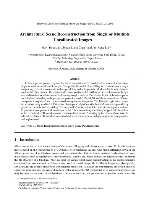
Abstract In this paper we present a system for the reconstruction of 3D models of architectural scenes from single or multiple uncalibrated images. The partial 3D model of a building is recovered from a single image using geometric constraints such as parallelism and orthogonality, which are likely to be found in most architectural scenes. The approximate corner positions of a building are selected interactively by a user and then further refined automatically using Hough transform. The relative depths of the corner points are calculated according to the perspective projection model. Partial 3D models recovered from different viewpoints are registered to a common coordinate system for integration. The 3D model registration process is carried out using modified ICP (iterative closest point) algorithm with the initial parameters provided by geometric constraints of the building. The integrated 3D model is then fitted with piecewise planar surfaces to generate a more geometrically consistent model. The acquired images are finally mapped onto the surface of the reconstructed 3D model to create a photo-realistic model. A working system which allows a user to interactively build a 3D model of an architectural scene from single or multiple images has been proposed and implemented. Key Words: 3D Model Reconstruction, Range Image, Range Data Registration.
遥感图像场景分类综述
人工智能及识别技术本栏目责任编辑:唐一东遥感图像场景分类综述钱园园,刘进锋*(宁夏大学信息工程学院,宁夏银川750021)摘要:随着科技的进步,遥感图像场景的应用需求逐渐增大,广泛应用于城市监管、资源的勘探以及自然灾害检测等领域中。
作为一种备受关注的基础图像处理手段,近年来众多学者提出各种方法对遥感图像的场景进行分类。
根据遥感场景分类时有无标签参与,本文从监督分类、无监督分类以及半监督分类这三个方面对近年来的研究方法进行介绍。
然后结合遥感图像的特征,分析这三种方法的优缺点,对比它们之间的差异及其在数据集上的性能表现。
最后,对遥感图像场景分类方法面临的问题和挑战进行总结和展望。
关键词:遥感图像场景分类;监督分类;无监督分类;半监督分类中图分类号:TP391文献标识码:A文章编号:1009-3044(2021)15-0187-00开放科学(资源服务)标识码(OSID ):Summary of Remote Sensing Image Scene Classification QIAN Yuan-yuan ,LIU Jin-feng *(School of Information Engineering,Ningxia University,Yinchuan 750021,China)Abstract:With the progress of science and technology,the application demand of remote sensing image scene increases gradually,which is widely used in urban supervision,resource exploration,natural disaster detection and other fields.As a basic image pro⁃cessing method,many scholars have proposed various methods to classify the scene of remote sensing image in recent years.This pa⁃per introduces the research methods in recent years from the three aspects of supervised classification,unsupervised classification and semi-supervised classification.Then,combined with the features of remote sensing images,the advantages and disadvantages of these three methods are analyzed,and the differences between them and their performance performance in the data set are com⁃pared.Finally,the problems and challenges of remote sensing image scene classification are summarized and prospected.Key words:remote sensing image scene classification;Unsupervised classification;Supervise classification;Semi-supervised clas⁃sification遥感图像场景分类,就是通过某种算法对输入的遥感场景图像进行分类,并且判断某幅图像属于哪种类别。
- 1、下载文档前请自行甄别文档内容的完整性,平台不提供额外的编辑、内容补充、找答案等附加服务。
- 2、"仅部分预览"的文档,不可在线预览部分如存在完整性等问题,可反馈申请退款(可完整预览的文档不适用该条件!)。
- 3、如文档侵犯您的权益,请联系客服反馈,我们会尽快为您处理(人工客服工作时间:9:00-18:30)。
Antonios Gasteratos1, Panagiotis Zafeiridis2, and Ioannis Andreadis2
1 Laboratory of Robotics and Automation, Section of Production Systems, Department of Production and Management Engineering, Democritus University of Thrace Building of University’s Library, Kimmeria, GR-671 00 Xanthi, Greece agaster@pme.duth.gr http://utopia.duth.gr/~agaster 2 Laboratory of Electronics, Section of Electronics and Information Systems Technology, Department of Electrical and Computer Engineering, Democritus University of Thrace Vassilisis Sophias 12, GR-671 00 Xanthi, Greece {pzafirid,iandread}@ee.duth.gr
2 Algorithm Description
2.1 Texture Feature Extraction The texture feature extraction of the proposed system relies on Laws texture measures [15], where the notion of “local texture energy” is introduced. The idea is to convolve the image with 5x5 kernels and then to apply a nonlinear windowing operation over the convolved image. In this way a new image results, each pixel of which represents the local texture energy of the corresponding pixel of the original image. Laws have proposed 25 individual zero-summing kernels, each describing a different aspect of the local texture energy. These kernels are generated by the one-dimensional kernels, shown in Figure 1. As an example of how the 2-dimensional kernels are generated, L5S5 results by multiplying the 1-dimensional kernel L5 with S5. Experiments with all the 25 kernels showed that, as far as our application is concerned, the most potent ones are R5R5, E5S5, L5S5 and E5L5. More specifically, applying each of these four masks to images of a certain class (sea, forest, etc.) the global texture descriptors were more concentrated than with the rest of the masks. These kernels were used to extract the four texture descriptors of the proposed system.
G.A. Vouros and T. Panayiotopoulos (Eds.): SETN 2004, LNAI 3025, pp. 63–71, 2004. © Springer-Verlag Berlin Heidelbratos, Panagiotis Zafeiridis, and Ioannis Andreadis
Abstract. Content based image retrieval is an active research area of pattern recognition. A new method of extracting global texture energy descriptors is proposed and it is combined with features describing the color aspect of texture, suitable for image retrieval. The same features are also used for image classification, by its semantic content. An exemplar fuzzy system for aerial image retrieval and classification is proposed. The fuzzy system calculates the degree that a class, such as sea, clouds, desert, forests and plantations, participates in the input image. Target applications include remote sensing, computer vision, forestry, fishery, agricultures, oceanography and weather forecasting. Keywords: CBIR, Machine intelligence, Fuzzy systems, Data fusion
1 Introduction
The recent improvements in network technologies lead to higher data transmission rates. Consequently this leads to faster internet connections around the globe. On the other hand one might say that the vast number of internet users necessitated the high speed internet connections and pushed the research to faster networks. No matter which comes first, the fast internet connections along with today’s powerful computers and the proliferation of the imaging devices (scanners, digital cameras etc) moved forward a relatively new branch of pattern recognition; the so-called contentbased image retrieval (CBIR). This is the retrieval of images on the basis of features automatically derived from the images themselves. The features most widely used are texture [1-3], color [4-6] and shape [7-9]. A plethora of texture features extraction algorithms exists, such as wavelets [10-12], mathematical morphology [13] and stochastic models [14], to mention few. A simple but efficient method to represent textures is using signatures based on texture energy [15, 16]. Energy images result from the convolution of the original image with special kernels representing specific texture properties. An attempt to describe the texture by means of color information was carried out in [17]. This method allows an effective evaluation of texture similarity in terms of color aspect and, therefore, to attribute textures to classes based on their color composition.
A review of the existing image retrieval techniques is presented in [18]. These are categorized into three groups: automatic scene analysis, model-based and statistical approaches and adaptive learning from user feedback. Conclusively, it is said that the CBIR is in its infancy and that, in order to develop truly intelligent CBIR systems, combination of techniques from the image processing and artificial intelligence fields should be tried out. In the present paper such an algorithm is proposed. It combines texture and color features by means of a least mean square (LMS) technique. The texture features of the images are extracted using the Laws convolution method [15, 16]. However, instead of extracting a new image each of its pixels describing the local texture energy, a single descriptor is proposed for the whole image. Each class of scenes corresponds to a certain band in the descriptor space. The color similarity is examined by means of its characteristic colors [17]. The same feature set can be used also for image classification, by its semantic content. The classification is performed by a fuzzy system. The membership functions (mf) of the proposed method are constructed by statistical analysis of the training features. As an example, a system that classifies aerial images is described. Experiments demonstrate the high efficiency of the proposed system. The use of these particular texture and color texture descriptors is attempted for the first time. The redundancy of texture information decreases the classification uncertainty of the system.