85.开发 XControl 2 - 创建
XControl技术
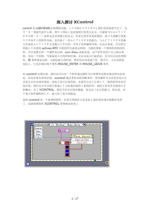
深入探讨XControlcontrol是LABVIEW8.x新增的功能,LV中的CONTROL我们是再熟悉不过了,这个"X"到底代表什么那,到NI网站上也没找到它的英文定义,可能相当与ACTIVEX中的"X"?虽然无法弄清楚它的定义,但是它的作用是清楚的,我个人理解它更象VC中MFC的控件自画,也具备了一些ACTIVEX的能力,与ACTIVEX的最大区别是ACTIVEX是独立于平台的,可用于各种编程环境,从这点来说,可以把它看做LV内部的 activex,MFC中的控件自画是这样的,当我们要做一个特殊形状的控件时,可以设置它的一个属性是自画,own draw,也就是说,这个控件是用户自己画出来的,比如一个按钮,当鼠标进入它的控制区域,会自动显示凸起状态,还可以自动改变颜色,IE菜单就是这样,当鼠标移入的时候,背景色自动变成兰色,离开后,又自动恢复,实际上,它是在响应两个事件,MOUSE_ENTER 和MOUSE_LEAVE事件.在xcontrol出现以前,我们也可以对一个控件通过属性节点和事件结构实现这种动态变化,但是有着本质的区别,xcontrol通过事件结构判断事件,利用属性节点改变其显示方式是完全在内部实现的,因此它是可以重用的,从使用方法上它和LV一般的控件没有任何区别,我们完全可以把它看成LV又给我们提供了新的控件,我的文章里多次提到AE的概念,有了XCONTROL,我们不但可以保存数据,而且有了显示的能力,所以说,对于基于组件编程的LV,能力有了很大的提高.虽然xcontrol是一个新增的特性,但是它的制作方法实际上我们或多或少地都涉及到了,这就使得制作XCONTROL变得相对容易了.可以看出,我们通过事件结构编程实现了当鼠标移入BOOLEAN控件区域时,BOOLEAN控件的CAPTION和COLOR自动发生了改变,但是所有的控制代码都是在主循环里完成了,是通过控件外部改变的,因此,我们无法重用这个控件,假如我们需要100个这样的控件,我们需要在事件结构中分别对 100个控件做类似的编程,这显然是非常麻烦的.最好的办法是让这段代码在控件内部完成,这样对于使用者来说,这和一般的控件没有区别,这样有效地实现了封装,所有的一切从用户的角度看,就象调用一个ACTIVEX.XCONTROL可以轻松实现这个功能我们知道LV的控件是面向对象的层次继承结构,每个控件都继承了它的父类的属性和方法,但是对于一个具体的控件,它的属性和方法都是固定的我们无法删除或者增加这个控件的属性和方法.对于XCONTROL,我们可以简单地理解成继承了一个基本控件,并在此基础上,用户增加的自己的属性和方法,是一个重新定义的,增加的大量功能的新的控件.下面看看制作XCONTROL的具体过程.这样一个基本的XCONTROL的结构就建立起来了,存储并重新命名lv自动生成两个自定义控件,分别是data.ctl和state.ctl,两个VI,分别是Facade.vi 和Init.vi这四个部分是任何XCONTROL都必须包括的基本构件。
Labview官方中级教程23 Xcontrol
中级 23:Xcontrol 0. 什么是 Xcontrol? XControl 实质上是一个控件 (可以是显示控件,也可以是控制控件),只是这个控件的功能和 Facade 都可以被自定义.在 LabVIEW 中,选择 New…>>Other Files>>XControl 就可以生成 一个 XControl 控件,如图 1 所示.图一:创建 XControl 图二是新创建的 XControl,可以看出包含如下的 2 个 VIs 和 2 个自定义控件. (1) (2) (3) (4) Data.ctl:定义 XControl 的数据类型. State.ctl:定义 XControl 的状态(可以封装内部的数据). Facade.vi:定义 XControl 的 Facade 和功能. Init.vi:定义 XControl 的初始状态.图二:新创建的 XControl 1. XControl 视频讲解 LabVIEW 网络讲坛之名家偶得:XControl 实战(上下集) /wv/app/doc/p/id/wv-2006 本讲引入了 XControl 的概念,阐述其与普通 LabVIEW 控件的区别.着重介绍了构建 XControl 所必须的元素,并演示如何创建一个简单的 XControl. /wv/app/doc/p/id/wv-2007 在上一讲的基础上,本讲通过演示逐一介绍了 XControl 的一些高级功能和调试的 Method. 并且和大家分享一下开发 XControl 中的一些小技巧. 2. XControl 使用方法 2.1 创建 XControl Method XControl Method 允许 XControl 的用户通过编程配置 XControl.通过调用节点调 用 XControlMethod.用户调用自定义的 XControlMethod 后,LabVIEW 将调用 FacadeVI. 如由于调用了 Method 而使显示状态发生改变,则“Facade”VI 将更新显示状态,使 XControl 的 Facade 得到更新.这种情况下,“Facade”VI 将生成显示状态更改事件. 在 XControl 库中,每个 XControl Method 都由 VI 实现.图三:配置 Method 2.2 创建 XControl Property图四:创建 Property 在 XControl 中创建的 Property 和 Method 都可以通过编程调用,这就是 XControl 的一个优势所在,可以自定义控件的属性和方法节点. 2.3 编辑 Façade.vi向“Facade“ VI 添加 LabVIEW 输入控件和显示控件以创建 XControl 的前面板.根 据出现在 XControlFacade 中的输入控件和显示控件,重新调整前面板的大小.图五:Xcontrol 自带控件 Container State 簇用于提供 XControl 的实例信息.Container State 簇包含三个元 素:显示控件?、运行模式?和引用句柄. Indicator?用于确认 XControl 实例是输入控件还是显示控件. Run Mode?用于确认使用 XControl 的 VI 的状态为运行中还是空闲.运行模式?设 为 TRUE 时,所属 VI 的状态为运行中. Refnum 是仅用于查询 XControl 信息的 XControl 实例的引用. “Facade”VI 改变数据或显示状态时,应更新 Action 簇并通知 LabVIEW 上述改变. Action 簇包含三个元素-Data Changed?、State Changed?和 Action Name. Data Changed?设为 TRUE 时“Facade”VI 将改变数据输出显示控件. State Changed?设为 TRUE 时“Facade”VI 将改变显示状态输出显示控件. Action Name 命名正在执行的 Action. Action 的名称在选中 Edit»Undo 选项时出现. 3. XControl 范例——Calculator XControlXcontrol 的界面就是 Façade.vi 的界面,这里提供的范例为 Calculator XControl,其 界面如图六所示:图六 Calculator XControl 界面(Façade.vi) Façade.vi 的程序框图如图七; 采用循环事件结构处理 Xcontrol 和界面控件产生的事件, 当 Display State Change 时,更新 Xcontrol 的输出(Output String); 在其他事件分支中,如点击 Equal,需要设置 State Changed 为真,并且在该分支中更 新 Xcontrol 的输出。
用XControl实现面向组件的编程

用XControl 实现面向组件的编程XControl 是LabVIEW 8 中出现的新功能。
面向组件的编程(Component Oriented Programming ,COP)技术建立在对象技术之上,它是对象技术的进一步发展,类这个概念仍然是组件技术中一个基础的概念,但是组件技术更核心的概念是接口。
组件技术的主要目标是复用--粗粒度的复用。
组件的核心是接口。
LabVIEW 为我们提供了大量漂亮的控件,可以让我们非常方便的就搭建出一个程序界面。
然而,对于追求完美的用户,LabVIEW 提供的为数有限的控件是远远不够的。
比如图1,是LabVIEW 8.2 一个新功能,导入导入共享库向导的界面。
在它右上方有四个按钮,这四个按钮有着特殊的外观图标,在LabVIEW 中没有直接提供这样的按钮。
要拥有这样的按钮,并保存下来以供再次使用,就只能自己制作一个自定义控件。
关于(用户自定义控件可以参考文章《用户自定义控件中Control, Type Def. 和Strict Type Def. 的区别》)图1:LabVIEW 8.2 中Import Shared Library 的界面自定义控件虽然可以定义控件的外观,但无法定义控件的行为,功能复杂一点的控件,.ctl 文件就爱莫能助了。
还是以图1 为例,它的Include Paths 控件是“一个”功能比较复杂的控件,它比LabVIEW 自带的列表框多了编辑功能。
用户添加或编辑一个路径时,这个控件要为用户在所编辑的项目提供直接编辑使用的文本框,和浏览路径按钮。
实际上这个编辑功能是由三个LabVIEW 提供的标准控件合作完成的:一个Listbox、一个String 和一个Button 控件。
他们的行为是在程序运行时决定的:当用户编辑控件中某一路径时,程序把String 和Button 挪到Listbox 上需要编辑的那一项,并遮挡住Listbox 原本的内容。
84.开发 XControl 1 - 设计
开发XControl 1 - 设计XControl 是LabVIEW 8 开始出现的一个制作LabVIEW 控件的工具。
与之前的用户自定义控件相比,用户自定义控件只能定义控件的界面,而XControl 还允许通过编写代码来定义控件的行为。
因此XControl 功能更加强大。
XControl 的主要优点是可以把界面元素与相关的代码封装在一起,从而方便发布和重用这些界面组件。
XControl 也有比用户自定义控件不足的地方,它开发起来更加困难;设计不合理的XControl会导致程序更加严重的问题。
需要开发一个新的控件之前,首先要考虑一下以何种方式实现这个控件。
如果这个控件极为特殊,只会用在某个特定的程序中,那么也许没有必要将其作为单独的控件;如果这个控件需要被多次使用,那么就应该考虑把它做成可重用的独立控件。
这个控件也许不包含任何特殊行为,比如一个用于表示坐标位置的控件由两个数值控件组成,程序只是使用它的值就可以了;或者一个新型按钮,仅外观与旧按钮不同,其它行为都与传统的按钮一模一样。
这样的控件适合使用用户自定义控件来制作。
如果新的控件需要重用,行为与已有其它控件又有较大差别,那么就要考虑XControl了。
比如:制作一个新按钮,但它比传统按钮多一个状态;或者它的界面带有动画效果;制作数值类控件但是用中国本土度量单位;基于图片控件,专用于绘制某种特殊曲线等。
我们前面提到的黑白棋的控件,既有特殊界面,又有特殊行为,又可以应用于不同软件中,非常适合做成XControl。
我们先来具体设计一下这个XControl 所需的界面和行为。
它的界面部分前面已经设计好了,直接拿来用就可以了。
不过在前文提到的几个设计方案中,我个人觉得Pict Ring 数组控件的那个解决方案,最能简化编程代码,所以我们采用这个界面方案。
XControl 在程序框图上的端点的输入输出数据应该是应用程序最经常需要与XControl交互的数据。
MMapXControl 用户说明

MMapXControl说明文档作者:嘉博世纪创建日期:2009年6月22日更新日期:2009年6月22日最新版本:3.0.0.0版权© 2009 为嘉博世纪所有文档管理¾修改记录日期 修改人 修改后版本 修改内容2009-6-22 嘉博世纪 3.0.0.0 发行第一版,基础API说明一、 控件安装与卸载1)控件的安装下载安装程序包MMapXControl.exe(视各服务器[见附录1]不同可能为.exe/.zip/.rar等,.zip/.rar需解压缩后执行安装)。
双击启动安装程序,如下图:单击“下一步”,进入安装目录选择:选定安装目录后,单击“安装”,执行安装过程。
安装完成后如下图:单击“完成”结束安装。
2)控件安装的文件文件名 文件路径 文件大小(字文件版本 文件功能节)MMapXControl.ocx 安装路径 345088 3.0.0.0 MMapXControl控件 Uninstall.exe 安装路径 66700 卸载安装程序Uninstall.ini 安装路径 1491 卸载安装配置文件 borlndmm.dll 系统路径 18432 5.0.12.34 Borland公司支持库cc3250mt.dll 系统路径 983040 5.0.1.80 Borland公司支持库3)控件的卸载可进入windows的“添加或删除程序”管理器进行卸载,也可进入安装路径执行Uninstall.exe进行卸载。
二、 控件的API与事件(针对开发者)MMapXControl.ocx控件在安装完之后,已默认注册到系统ActiveX控件中,名称为“MMapXControl”,开发者根据各自使用的开发工具(如Visual C++6.0,Visual Basic,Visual Studio .net,Delphi,C++ Builder等工具)进行加载。
MMapXControl.ocx控件包含丰富的API和Event支持,详细介绍如下(部分代码以Visual C++ 6.0环境为范例)。
86.开发 XControl 3 - 实现功能控件
开发XControl 3 - 实现功能控件XControl 有两个功能控件,本别定义XControl的数据类型,和XControl使用到的内部数据的数据类型。
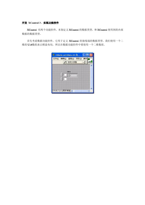
首先考虑数据功能控件,它用于定义XControl的接线端的数据类型。
我们使用一个二维的U16数组表示棋盘布局,所以在数据功能控件中要使用一个二维数组。
其次就要来考虑状态功能控件,这个控件类型的数据在XControl的功能VI中又被称为显示状态。
但它实际上的用途并不局限于帮助显示,实际上,XControl运行所需的全部变量,都应当被包含在这个功能控件中。
左面这幅图就是我所列出的运行一个黑白棋XControl所需的一些变量。
在我们编写的黑白棋程控件中,将会用到一下内部数据:method,当用户运行一个XControl的方法时,设置这一变量。
这一变量对应每个方法有不同的值。
这样,在XControl的外观功能VI中,就可以知道用户调用的是什么方法了。
current color,用于表明当前应该落什么颜色的棋子。
available black position,黑色棋子可以防止的位置。
available white position,白色棋子可以防止的位置。
Interactive Action,是一个用户自定义事件。
当用户在棋盘上落下一子时,XControl就产生这个事件,通知使用了它的VI。
row 和column 用于记录上次落子的位置。
先不需了解这里边每一个数据具体的含义和用法。
在后面使用到它们的时候还会详细介绍。
实际在编写XControl的时候,也不需要一次把状态功能控件就设计好。
可以一边实现XControl的功能,一边对其进行补充。
Oracle Exalogic Elastic Cloud X2-2 用户指南说明书

Oracle® Enterprise Manager Ops CenterEnabling Single Root Input Output Virtualization in Exalogic Elastic Cloud12c Release 1 (12.1.2.0.0)E35262-01November 2012This guide provides an end-to-end example for how to use Oracle Enterprise ManagerOps Center.IntroductionOracle Exalogic Elastic Cloud X2-2 solution includes a set of compute nodesinterconnected through QDR InfiniBand IO Fabric. In order to be able to virtualize theInfiniBand IO of Exalogic compute nodes, the Single Root Input Output Virtualization(SR-IOV) option must be enabled in BIOS.After compute node ILOM and BIOS is updated, the BIOS configuration settings of theExalogic node are set to default, leaving the SR-IOV settings disabled. For properfunctioning of the appliance, this option has to be re-enabled. You can change theSR-IOV settings in BIOS using the following procedures.■Enabling Single-Root Input Output Virtualization Using Oracle EnterpriseManager Ops Center UI■Enabling Single-Root Input Output Virtualization using ILOM CLI CommandsBoth these procedures are explained in this document.What You Will NeedYou will need the following to enable single-root input output virtualization:■ A configured Enterprise Controller■Oracle Exalogic Elastic Cloud (version 2.2 or later) installed on Oracle EnterpriseManager Ops Center■Ensure popup is enabled on the web browser■You must have the role of System Admin to enable SR-IOV actions■Login credentials to login to ILOM (administrative login credentials)Enabling Single-Root Input Output Virtualization Using OracleEnterprise Manager Ops Center UIIf Oracle Enterprise Manager Ops Center is available and fully functional, you can usethis procedure to enable single-root IO virtualization through the Oracle EnterpriseManager Ops Center UI.1.On the Navigation pane, under Assets, select a Server.2.On the Actions pane, click Launch LOM Controller. The web-based ILOM loginscreen for the asset opens.3.Enter the User Name and Password (Admin login credentials for the serviceprocessor of the asset) and click Log In.4.After logging in, click Remote Control, then click Host Control.5.In the Next Boot Device field, select BIOS.6.Click Save.7.Click the Logout button on the top right corner of the screen to logout of LOMController.■The server moves into locked state indicated by a padlock on the OS of the server.8.In the Navigation pane, under Assets, expand the Server node that you have justedited and select the hypervisor node under it.9.On the Actions pane, click Reboot Oracle VM Server Host.10.Click Reboot Oracle VM Server. The VM server is rebooted.11.On the Navigation pane, under Assets, select the server.12.In the center pane, click the Console tab, then click the Enable Console Connectionicon.■Wait until the job is complete. The BIOS menu opens.13.In the BIOS menu, using arrow keys, select Advanced, then select I/OVirtualization.14.Change the SR-IOV Supported value to Enabled.15.Press Esc key to go back to the Main menu. Using the arrow key, select Exit.16.Click OK to save the changes and exit.■The server reboots and the Operating System is started. This might take a few minutes. After the server has rebooted, the padlock icon on the OS disappearsand the OS is ready to host the virtual guests.17.Click Disable the Console Connection icon to disable the console.Enabling Single-Root Input Output Virtualization using ILOM CLI CommandsIf Oracle Enterprise Manager Ops Center is not installed, you can enable SR-IOV using ILOM CLI commands.1.Login to the ILOM console using SSH and your admin login credentials.2.Type ssh root@<xxx.xx.xx.x> to log in to the ILOM console (xxx.xx.xx.xx is the IP ofthe ILOM).Run the following commands after logging in to the server’s LDOM CLI console.1.Type set /HOST boot_device=BIOS .2.Type reset /SYS .3.Type start /SP/console .■It might take a few minutes for the BIOS menu to appear.4.In the BIOS menu, using arrow keys, select Advanced, then select I/O Virtualization.5.Change the SR-IOV Supported value to Enabled.6.Press Esc key to go back to the Main menu. Using the arrow key, select Exit.7.Click OK to save the changes and exit.The server reboots and the Operating System is started. This might take a fewminutes. After the server has rebooted, the padlock icon on the OS disappears and the OS is ready to host the virtual guests.Related Articles and ResourcesThe following chapter in the Oracle Enterprise Manager Ops Center Feature Reference Guide contains more information:Note:The ILOM CLI console IP address is read from the ECUconfiguration spreadsheet.■Oracle Exalogic Elastic CloudSee the How To library at/pls/topic/lookup?ctx=oc121&id=howtoDocumentation AccessibilityFor information about Oracle's commitment to accessibility, visit the Oracle Accessibility Program website at/pls/topic/lookup?ctx=acc&id=docacc.Access to Oracle SupportOracle customers have access to electronic support through My Oracle Support. For information, visit /pls/topic/lookup?ctx=acc&id=info or visit /pls/topic/lookup?ctx=acc&id=trs if you are hearing impaired.Oracle Enterprise Manager Ops Center Enabling Single Root Input Output Virtualization in Exalogic Elastic Cloud, 12c Release 1 (12.1.2.0.0)E35262-01Copyright © 2007, 2012, Oracle and/or its affiliates. All rights reserved.This software and related documentation are provided under a license agreement containing restrictions on use and disclosure and are protected by intellectual property laws. Except as expressly permitted in your license agreement or allowed by law, you may not use, copy, reproduce, translate, broadcast, modify, license, transmit, distribute, exhibit, perform, publish, or display any part, in any form, or by any means. Reverse engineering, disassembly, or decompilation of this software, unless required by law for interoperability, is prohibited.The information contained herein is subject to change without notice and is not warranted to be error-free. If you find any errors, please report them to us in writing.If this is software or related documentation that is delivered to the U.S. Government or anyone licensing it on behalf of the U.S. Government, the following notice is applicable:U.S. GOVERNMENT END USERS: Oracle programs, including any operating system, integrated software, any programs installed on the hardware, and/or documentation, delivered to U.S. Government end users are "commercial computer software" pursuant to the applicable Federal Acquisition Regulation and agency-specific supplemental regulations. As such, use, duplication, disclosure, modification, and adaptation of the programs, including any operating system, integrated software, any programs installed on the hardware, and/or documentation, shall be subject to license terms and license restrictions applicable to the programs. No other rights are granted to the U.S. Government.This software or hardware is developed for general use in a variety of information management applications. It is not developed or intended for use in any inherently dangerous applications, including applications that may create a risk of personal injury. If you use this software or hardware in dangerous applications, then you shall be responsible to take all appropriate fail-safe, backup, redundancy, and other measures to ensure its safe use. Oracle Corporation and its affiliates disclaim any liability for any damages caused by use of this software or hardware in dangerous applications. Oracle and Java are registered trademarks of Oracle and/or its affiliates. Other names may be trademarks of their respective owners.Intel and Intel Xeon are trademarks or registered trademarks of Intel Corporation. All SPARC trademarks are used under license and are trademarks or registered trademarks of SPARC International, Inc. AMD, Opteron, the AMD logo, and the AMD Opteron logo are trademarks or registered trademarks of Advanced Micro Devices. UNIX is a registered trademark of The Open Group.This software or hardware and documentation may provide access to or information on content, products, and services from third parties. Oracle Corporation and its affiliates are not responsible for and expressly disclaim all warranties of any kind with respect to third-party content, products, and services. Oracle Corporation and its affiliates will not be responsible for any loss, costs, or damages incurred due to your access to or use of third-party content, products, or services.。
85.开发 XControl 2 - 创建

开发XControl 2 - 创建
在项目浏览器上,点击鼠标右键,选择“新建->XControl”,就可以创建一个新的XControl。
XControl 在结构上是一种特殊的库,他包含一些特定的更能VI,和一些可选的属性、方法VI及其它相关文件。
在新建的XControl 上已经包含了4个必须的功能VI(控件):数据、状态、外观、初始化。
XControl 还有两个可选的功能VI:反初始化和转换状态以保存。
简要介绍这几个功能VI的功能是:
数据:用来定义XControl的数据类型。
状态:定义所有XControl内部使用到的数据。
外观:这是XControl中最主要的功能VI,用以实现XControl的界面和界面上的行为。
初始化:设置XControl的初始状态。
反初始化:负责清理工作。
转换状态以保存:用于把XControl内部的某些数据保存在使用它的VI中。
下面对XControl做一些基础的设置,比如修改它的图标、版本号等,然后保存。
XControl功能VI的文件名并不一定与其功能名相同。
比如,为了方便更多人使用,我使用了英文名称来保存我的XControl:。
xControl的制作步骤

描述当布尔值为F时,字符串为XXXXX,为T时,自动改变为TTTTT。
对应生成的显示控件布尔控件只显示字符串。
步骤新建一个xControl打开LabVIEW,新建—选择XControl,首先保存。
默认名称保存之后保存。
然后打开xControl 的工程进行重命名。
如果在保存的时候就修改名称,会提示一直保存。
图 1 新建图 2 重命名图 3 新工程新建的工程有四部分:初始化、数据、外观、状态。
先从最基本的入手。
打开外观。
控件样式放置一个布尔控件和一个字符串控件(注意是两个分开的控件,不是簇)。
调整好大小。
初次打开“外观.vi”时,会有提示信息告诉你如何设置界面。
本次使用固定大小的控件。
图 4 外观这一步就决定了控件在使用时的外观样式。
完成后保存关闭。
数据类型刚界面放置的是两个控件。
每个控件只能代表一类值,这样如何选择?为了让这个控件能包含布尔和字符串的信息,我们将数据类型设为一个簇。
打开“数据.ctl”,将“外观.vi”里面的两个控件放到一个簇里面,作为本次的“值“。
图 5 数据以上操作就决定了,你的控件在使用时,程序面板上的显示数据类型。
具体操作第一步以上完成之后,再打开“外观.vi”,设计控件的逻辑。
打开“外观.vi”的程序面板后,里面的结构是已经设计好的。
自带以下几个事件:超时、数据更改、显示状态更改、方向更该、执行状态更该。
在下面的具体操作中,将按照我的理解进行描述。
Data In表示的是控件的值传递,注意区别于界面(即自己放置的两个控件)显示。
Container State表示控件是输入控件还是显示控件,这个影响外观状态。
我们知道,同一个类型的控件输入和显示的外观是不一样的。
Action表示的是控件的值改变还是状态改变,这个是要通知LabVIEW进行处理的,很重要的一个输入。
首先添加自定义的事件结构,即布尔值发生变化时字符串的显示改变。
图 6 添加事件结构在添加的事件结构里面,除了要更新自身两个控件的状态,还需更新整个控件的值,即簇的值。
labview深入探索xcontrol
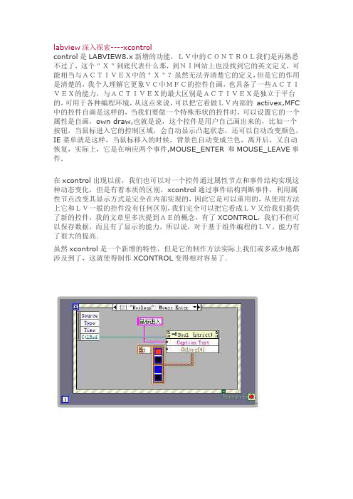
labview深入探索----xcontrolcontrol是LABVIEW8.x新增的功能,LV中的CONTROL我们是再熟悉不过了,这个"X"到底代表什么那,到NI网站上也没找到它的英文定义,可能相当与ACTIVEX中的"X"?虽然无法弄清楚它的定义,但是它的作用是清楚的,我个人理解它更象VC中MFC的控件自画,也具备了一些ACTIVEX的能力,与ACTIVEX的最大区别是ACTIVEX是独立于平台的,可用于各种编程环境,从这点来说,可以把它看做LV内部的activex,MFC 中的控件自画是这样的,当我们要做一个特殊形状的控件时,可以设置它的一个属性是自画,own draw,也就是说,这个控件是用户自己画出来的,比如一个按钮,当鼠标进入它的控制区域,会自动显示凸起状态,还可以自动改变颜色,IE菜单就是这样,当鼠标移入的时候,背景色自动变成兰色,离开后,又自动恢复,实际上,它是在响应两个事件,MOUSE_ENTER 和MOUSE_LEAVE事件.在xcontrol出现以前,我们也可以对一个控件通过属性节点和事件结构实现这种动态变化,但是有着本质的区别,xcontrol通过事件结构判断事件,利用属性节点改变其显示方式是完全在内部实现的,因此它是可以重用的,从使用方法上它和LV一般的控件没有任何区别,我们完全可以把它看成LV又给我们提供了新的控件,我的文章里多次提到AE的概念,有了XCONTROL,我们不但可以保存数据,而且有了显示的能力,所以说,对于基于组件编程的LV,能力有了很大的提高.虽然xcontrol是一个新增的特性,但是它的制作方法实际上我们或多或少地都涉及到了,这就使得制作XCONTROL变得相对容易了.可以看出,我们通过事件结构编程实现了当鼠标移入BOOLEAN控件区域时,BOOLEAN控件的CAPTION和COLOR自动发生了改变,但是所有的控制代码都是在主循环里完成了,是通过控件外部改变的,因此,我们无法重用这个控件,假如我们需要100个这样的控件,我们需要在事件结构中分别对100个控件做类似的编程,这显然是非常麻烦的.最好的办法是让这段代码在控件内部完成,这样对于使用者来说,这和一般的控件没有区别,这样有效地实现了封装,所有的一切从用户的角度看,就象调用一个ACTIVEX.XCONTROL可以轻松实现这个功能我们知道LV的控件是面向对象的层次继承结构,每个控件都继承了它的父类的属性和方法,但是对于一个具体的控件,它的属性和方法都是固定的我们无法删除或者增加这个控件的属性和方法.对于XCONTROL,我们可以简单地理解成继承了一个基本控件,并在此基础上,用户增加的自己的属性和方法,是一个重新定义的,增加的大量功能的新的控件.下面看看制作XCONTROL的具体过程.这样一个基本的XCONTROL的结构就建立起来了,存储并重新命名lv自动生成两个自定义控件,分别是data.ctl和state.ctl,两个VI,分别是Facade.vi和Init.vi这四个部分是任何XCONTROL都必须包括的基本构件。
迅饶 OPC服务器 X2OPC(免费版)使用手册说明书

OPC服务器X2OPC(免费版)使用手册上海迅饶自动化科技有限公司目录1 前言 (1)1.1声明 (1)1.2技术支持 (1)2 概述 (2)2.1功能描述 (2)2.2运行环境 (2)2.3应用领域 (2)3 使用说明 (4)3.1注册OPC服务器 (4)3.2进入程序 (5)3.3添加驱动 (6)3.4添加通道 (6)3.5添加设备 (7)3.6添加标签 (7)3.7启动OPC服务器 (10)4 OPC客户端软件访问 (14)5补充说明 (18)5.1语言设置 (18)5.2WEB浏览 (18)6 JS脚本逻辑控制 (20)6.1操作步骤 (20)6.2函数说明 (25)6.3使用范例 (27)7 常见问题说明 (29)7.1调用WEB服务器方法失败 (29)7.2对接N IAGARA N4只能扫到设备不能扫到点 (29)1前言1.1声明本手册属于上海迅饶自动化科技有限公司及授权许可者版权所有,保留一切权利,未经本公司书面许可,任何单位和个人不得擅自摘抄、复制本书内容的部分或全部。
由于产品版本升级或其他原因,本手册内容有可能变更。
上海迅饶自动化科技有限公司保留在没有任何通知或者提示的情况下对本手册的内容进行修改的权利。
本手册仅作为使用指导,本公司尽全力在本手册中提供准确的信息。
1.2技术支持●技术支持邮箱:*********************●技术支持热线电话:************●网址:或2 概述2.1功能描述●X2OPC是一款OPC服务器。
顾名思义X代表各个厂商不同的通信协议,在免费版里仅代表OPC XML-DA,2是To的谐音表示转换,OPC表示最终转换成OPC服务器。
X2OPC(免费版)的主要功能是通过OPC接口开放网关的数据转换成OPC服务器。
X2OPC(免费版)支持XML-DA 1.0规范,在PC端ProgID为SunFull. X2OPC.1。
并提供一个简易的人机界面给用户,用来编辑和配置TAG;保存或者打开x2o工程文件;自动搜索点表;导入或者导出CSV档;复制设备、组和TAG对象。
Labview 学习笔记
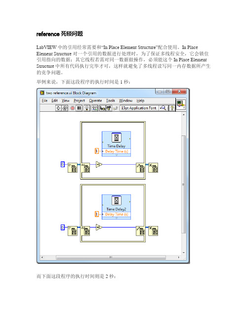
reference死锁问题LabVIEW中的引用经常需要和“In Place Element Structure”配合使用。
In Place Element Structure 对一个引用的数据进行处理时,为了保证多线程安全,它会锁住引用指向的数据;其它线程若需对同一数据做操作,必须能这个In Place Element Structure中所有代码执行完毕才可,这样就避免了多线程读写同一内存数据所产生的竞争问题。
举例来说,下面这段程序的执行时间是1秒:而下面这段程序的执行时间则是2秒:因为第二段程序中的两个In Place Element Structure必须顺序执行。
有了“锁住”这个操作,就有不小心造成死锁的可能。
比如对于同一数据的引用,千万不能嵌套使用In Place Element Structure,否则就会死锁:在上面这个示例中,程序运行至内层的In Place Element Structure,就会停在这里等外层In Place Element Structure运行结束,释放它锁住的数据;而对于外层In Place Element Structure来说,它内部的全部代码要运行结束,它才结束。
因而它们相互等待,造成了死锁。
Packed Project Libraries 2 –与Library的比较acked Project Library 从名字上来看,就是被包装好了的Project Library。
Project Library 是编程时候由程序员创建出来的。
比如下图这个工程,我在里面创建了一个叫做“My Algorithm Library.lvlib”的工程库。
它包含两个VI,其中一个是私有的。
Packed Project Library 并不是手工创建的,他是通过一个项目的生成规范,从Project Library 编译而来的。
比如上图的项目,我创建了一个Packed Library类型的生成规范。
92.开发 XControl 9 - 使用 XControl
开发XControl 9 - 使用XControl
关于XControl还有好几个方面的知识点没有介绍到,包括:版本控制、错误处理、得到调用VI的信息、调试、调整界面大小、发布快捷菜单、动画的实现、一些注意事项等。
不过,这些细节问题在这个黑白棋控件中没有体现出来。
所以以后有机会再讨论。
作为这一组XControl话题的结束篇,介绍一下演示使用黑白棋控件的范例。
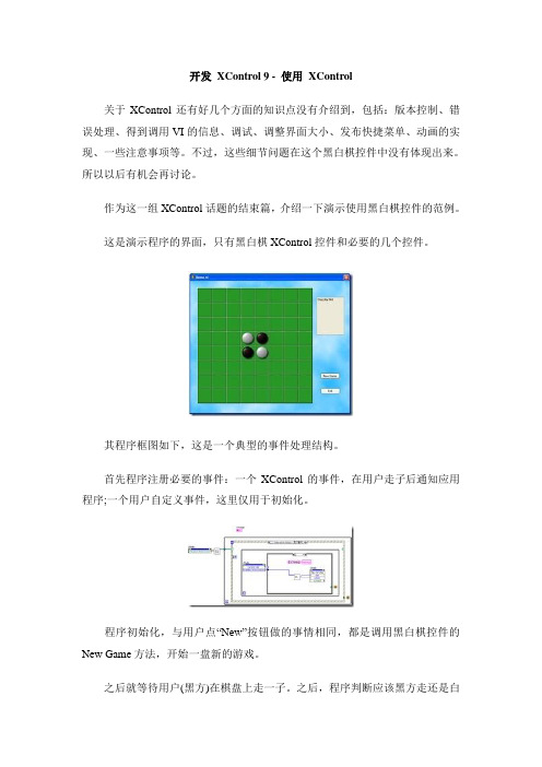
这是演示程序的界面,只有黑白棋XControl控件和必要的几个控件。
其程序框图如下,这是一个典型的事件处理结构。
首先程序注册必要的事件:一个XControl的事件,在用户走子后通知应用程序;一个用户自定义事件,这里仅用于初始化。
程序初始化,与用户点“New”按钮做的事情相同,都是调用黑白棋控件的New Game方法,开始一盘新的游戏。
之后就等待用户(黑方)在棋盘上走一子。
之后,程序判断应该黑方走还是白
方走。
如果轮到白方走,程序就在所有可以落子的地方随机选出一个位置,走一白子。
(程序没有实现人工智能部分)
黑白都不可走时,程序计算输赢。
Digilent XC2-XL系统板用户说明书

D i g i l e n t X C2-X L™S y s t e m B o a r d R e f e r e n c e M a n u a l®Revision: May 11, 2004 215 E Main Suite D | Pullman, WA 99163(509) 334 6306 Voice and Fax OverviewThe Digilent XC2-XL System Board (the XC2-XL™) is a self-contained circuit development platform that contains a Xilinx CoolRunner-II XC2C256 CPLD and a Xilinx XC9572XL CPLD. The XC2-XL is an ideal platform for CPLD-based circuit design using the latest Xilinx CAD tools. It provides a JTAG programming circuit, power supplies, a clock source, and basic I/O devices, so that circuits can be implemented immediately without the need for any other components. All CPLD signals are brought to expansion connectors, allowing accessory circuits to be constructed in the on-board prototype area, or attached via an expansion board. The XC2-XL is compatible with all versions of Xilinx CAD tools, including the free WebPack tools available at the Xilinx website. XC2-XL features include:∙ A Xilinx CoolRunner-II XC2C256 CPLD in a TQ144 package;∙ A Xilinx XC9572XL CPLD in a VQ44 package;∙JTAG ports to both CPLDs that can be independently enabled or disabled;∙Flexible power delivery using a wall-plug transformer, batteries, or external supplies; ∙ A socketed oscillator (1.8432MHz included;clocks up to 100+MHz can be used);∙Full routing of all I/O signals from both CPLDs to expansion connectors;∙ A button and two LEDs for basic I/O;∙Non-volatility – as with all Xilinx CPLDs, designs remain after power is removed. Several expansion boards containing a variety of I/O devices are available for the XC2-XL. These fully assembled and tested boards can be used to quickly and easily enhance the features of the XC2-XL. See the Digilent website at /xc2xl for more information.Functional DescriptionThe XC2-XL provides a minimal system that can be used to rapidly implement CPLD-based circuits, and to gain exposure to Xilinx CAD tools and CPLD-oriented design methods. The XC2-XL provides only the essential circuits needed to support the CPLDs, including power supplies, a clock source, and basic I/O (a pushbutton and two LEDs). All available I/O signals are routed to expansion connectors that mate with 40-pin, 100 mil spaced DIP headers available from several distributors. The on-board power supplies and clock source can easily be disconnected from the CPLDs so that external power and clock signals can be used. Power supply design and decoupling follow recommended design practices, so the XC2-XL has stable, low noise supplies regardless of the power source used.CPLD programming is accomplished via a 6-pin, 3.3V JTAG programming header that is compatible with a variety of cables, including the JTAG3 cable from Digilent, the Parallel-3 or –4 cables from Xilinx, as well as cables from other vendors.The XC2-XL measures 5.25” x 5.25”, and it contains an 18-hole x 46-hole wire wrap area. The wire-wrap area can accommodate a self-adhesive solderless breadboard, allowing flexibility in accessory circuit construction.Both CPLDs on the XC2-XL board are loaded with a sample configuration during board test. This basic configuration flashes the on-board LEDs at different rates that are selectable using the on-board button. This configuration, which can be downloaded from the Digilent or Xilinx websites, serves as a quick board check as well as a basic reference design.Power SuppliesThe CoolRunner-II requires three power supplies (V CORE, V IO1, and V IO2), so the XC2-XL has three separate circuits for power delivery. The V CORE and V IO1 supplies are routed only to the CoolRunner 2, and they are set to 1.8V and 3.3V respectively. V IO2 is routed to both CPLDs, and it is also set to 3.3V. V CORE is generated from a 1.8V LM1117 LDO regulator that can supply up to 800mA of current. Jumper block JP3 allows V CORE to be disconnected from the on-board regulator so that it can be brought in from an external supply. V IO1 and V IO2 both arise from the same 3.3V LM317 regulator that can supply up to 1.5A of current. Jumper-blocks JP2 and JP4 can disconnect V IO1 and V IO2 from the on-board regulators so that external I/O supplies can be used.Jumper block JP1 selects whether V IO is supplied from the 3.3V regulator, or from a source connected to J2. Regardless of the JP1 setting, the V CORE regulator is used to generate the 1.8V supply. Jumper blocks JP2, JP3, and JP4 select whether V IO1, V CORE, and V IO2 are supplied from on-board or external supplies. The figure below shows the power supply routing and typical jumper settings.Power can be supplied to the XC2-XL using any one of three modes. Wall-plug mode supplies power from any 5VCD-9VDC wall-plug-transformer supply connected to the power jack (J9) on the XC2-XL. The supply must source at least 250mA of current, and it must use a center-positive, 2.1mm ID/5.5mm OD connector. Battery mode supplies power from a battery pack (or other DC source) connected to the J2 header on the XC2-XL. The batteries must output between 2.8V and 3.6V. External mode uses the J8 header to bring regulated supplies from any external source. In the wall-plug mode, the V CORE and V IO regulators are used, so there is little chance of damaging the CPLDs by using incorrect supply voltages (both regulators can handle up to 18VDC). In battery mode, theV CORE regulator is used, but the supplied voltage directly drives the V IO connections, so care must be taken to ensure no more than3.8V is applied. In external mode, noregulators are used, so care must be taken to ensure CPLD voltage requirements are met.CPLD ConfigurationThe CPLDs on the XC2-XL are connected in a JTAG scan chain as shown in the figure below. Either device can be removed from the chain by setting jumper blocks P5, JP6, JP9, and JP10 appropriately. The scan chain originates from a 6-pin header connector that iscompatible with the JTAG3 cable from Digilent, and the P-3 and P-4 cables from Xilinx.Both ICs IC2 only IC1 only InvalidTMS TDI TDO TCK GND VDDJ P 5/J P 10J P 6/J P 9J P 5/J P 10J P 6/J P 9J P 5/J P 10J P 6/J P 9J P 5/J P 10J P 6/J P 9= jumper shorting blockFigure 3. JTAG signal routingOscillatorThe XC2-XL uses a half-size 8-pin DIPoscillator in an 8-pin socket. The board ships with a 1.842MHz oscillator, but oscillators from 32KHz to 100MHz can be used. The oscillator is connected to the GCK2 input on both CPLDs.Figure 4. Clock signalsNote: The IC1 and IC2 legends are incorrect on the circuit board silkscreen; they arecorrect in the figure above.Pushbutton and LEDsA pushbutton and two LEDs provide basic I/O functions on the XC2-XL. The LED can be illuminated to verify that configuration was successful, or flashed at a given rate to indicate a particular status. The pushbutton can be used to provide a basic reset function, or to select an operating mode. Thepushbutton drives the GSR input on both CPLDs, and the LED is driven from a general I/O pin.Figure 5. Pushbutton and LEDsExpansion ConnectorsFour expansion connectors have been provided to allow XC2 designs to be expanded on the included prototype area, or by attaching peripheral boards. The connectors use 2 x 20, 100-mil spaced right-angle sockets so that standard headers can be used on peripheral boards. Several Digilent expansion boards can be used with the XC2-XL, including solderless breadboards, wire-wrap boards, and analog and digital I/O boards. See Digilent’s website at /xc2xl for more information on available expansion boards.All available signals are routed from the two CPLDs to the connectors as shown in the figure below. VCC (3.3V regulated), VU (depends on power supply used), and GND are also routed to the connector so that attached devices can draw power from theXC2-XL board. If the 3.3V regulated supply is used, no more than 1.5A should be drawn. Table 1 below shows XC2-XL expansion connector pinouts.Figure 5. Expansion Connectors CPLDsThe XC2-XL contains a Xilinx XC2C256 CoolRunner II CPLD in a TQ144 package, and an XC9572 CPLD in a VQ44 package. Both CPLDs have a clock source, pushbutton input, LED output, and connections to the JTAG programming signals. Other than these connections, all I/O signals are routed to the expansion connectors. CPLD pinouts are provided in tables 2 and 3 below.The CPLDs can be programmed using the Xilinx ISE/WebPack software and the JTAG3 cable from Digilent (the P-3 or P-4 programming cable from Xilinx can also be used).Please see the data sheets for the CPLDs available at the Xilinx web site for more information.。
Delphi编写ActiveX控件(OCX控件)的知识和样例(有详细步骤)

Delphi编写ActiveX控件(OCX控件)的知识和样例(有详细步骤)⼀、ActiveX应⽤情况简介:ActiveX控件也就是⼀般所说的OCX控件,它是 ActiveX技术的⼀部分。
ActiveX是微软公司推出的基于组件对象模型COM的技术,包括对Windows 32位应⽤编程接⼝(Win32 API)和组件对象模型的⼀系列扩充和增强,⽬标是把计算机桌⾯环境与因特⽹环境集成起来,同时保护在Windows技术中现有的开发投资。
微软的 ActiveX技术根本上就是修改过的OCX技术,使它能够跨越Internet,主要是使⽤WWW来传递控件。
ActiveX控件可以被集成到很多⽀持ActiveX的应⽤当中去,或者直接⽤来扩展应⽤的功能,这些⽀持ActiveX的应⽤包括C++ Builder、Delphi、Visual dBASE、 Visual Basic、Visual C++、Internet Explorer、Netscape Navigator等。
ActiveX控件还可以使⽤在因特⽹上,在⽹页上使⽤它来发布信息、处理与⽤户的交互,但是需要使⽤⽀持ActiveX的浏览器才能阅读这些⽹页。
⽬前已经开发出来的ActiveX控件越来越多,由于ActiveX控件具有很好的特性,我们可以在编程的时候选择使⽤合适的控件来加快⾃⼰的应⽤开发。
可以不夸张地说,ActiveX控件是Windows平台编程必不可少的法宝。
使⽤ActiveX控件是相对⽐较简单的。
但是,开发ActiveX控件并不是⼀件简单的事情,必须要熟悉⽽不只是了解ActiveX技术才能开发出好的ActiveX控件。
⽽COM、OLE等ActiveX技术对于⼀般的程序员来说,是⽐较复杂难懂的。
所以,ActiveX控件的开发者⼀般都是“⽼鸟”级别的程序员。
但是如果您有了Inprise公司的Borland Delphi,那⼜另当别论了。
Delphi作为Windows平台上最优秀的程序开发⼯具之⼀,为ActiveX控件的开发提供了强有⼒的⽀持,让您轻松地开发ActiveX控件。
xc2c64 开发流程

xc2c64 开发流程下载温馨提示:该文档是我店铺精心编制而成,希望大家下载以后,能够帮助大家解决实际的问题。
文档下载后可定制随意修改,请根据实际需要进行相应的调整和使用,谢谢!并且,本店铺为大家提供各种各样类型的实用资料,如教育随笔、日记赏析、句子摘抄、古诗大全、经典美文、话题作文、工作总结、词语解析、文案摘录、其他资料等等,如想了解不同资料格式和写法,敬请关注!Download tips: This document is carefully compiled by theeditor. I hope that after you download them,they can help yousolve practical problems. The document can be customized andmodified after downloading,please adjust and use it according toactual needs, thank you!In addition, our shop provides you with various types ofpractical materials,such as educational essays, diaryappreciation,sentence excerpts,ancient poems,classic articles,topic composition,work summary,word parsing,copy excerpts,other materials and so on,want to know different data formats andwriting methods,please pay attention!xc2c64 是一款可编程逻辑器件,以下是一般的开发流程:1. 设计规划:确定项目需求和功能,制定设计方案。
C#二次开发教程(Block UIStyler)
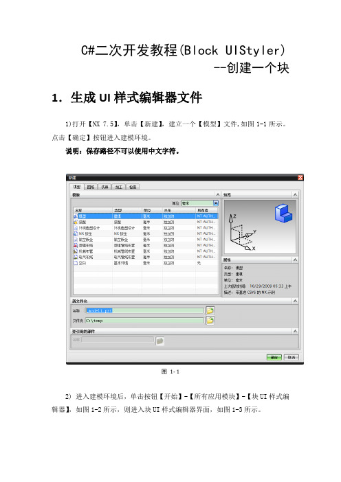
C#二次开发教程(Block UIStyler)--创建一个块1.生成UI样式编辑器文件1)打开【NX 7.5】,单击【新建】,建立一个【模型】文件,如图1-1所示。
点击【确定】按钮进入建模环境。
说明:保存路径不可以使用中文字符。
图1- 12) 进入建模环境后,单击按钮【开始】-【所有应用模块】-【块UI样式编辑器】,如图1-2所示,则进入块UI样式编辑器界面,如图1-3所示。
图1- 2图1- 33)根据对话框的需要,在【Block Catalog】中选择适当的窗体如图1-4所示,对于创建一个长方体来说,选择【数字】-【双倍】如图1-5所示,长、宽、高为三项,故点击三次【双倍】如图1-6所示。
图1- 4图1- 5图1- 64)在【对话框】-【对话框】中分别修改Dialog、Group、double0、double01、double02的Label属性,如图1-7所示。
图1- 75)将Dialog的Label属性改为“创建”、Group的Label属性改为“长方体”、double0的Label属性改为“长”、double01的Label属性改为“宽”、double02的Label属性改为“高”,修改后的对话框如图1-8所示。
图1- 86)单击【代码生成】,右击【语言】-【C#】,如图1-9所示。
图1- 97)单击【文件】-【另存为】如图1-10所示,弹出【保存对话框文件】,设置文件名,选择路径后单击平【ok】保存,如图1-11所示。
图1- 10图1- 118)系统自动提示UI样式编辑器文件生成,如图1-12所示。
此时在保存路径的位置就生成了两个文件dlx文件与cs文件,如图1-13所示。
图1- 12图1- 139)关闭UG,无需保存任何信息。
2. 文件配置1)创建工作目录如路径如F:\ Block在该路径下新建两个文件夹application及startup。
注意:创建的路径不能包含中文字符,如“F:\新建文件夹\Block”。
Linux ALSA声卡驱动之四:Control设备的创建

Linux ALSA声卡驱动之四:Control设备的创建Control接口Control接口主要让用户空间的应用程序(alsa-lib)可以访问和控制音频codec芯片中的多路开关,滑动控件等。
对于Mixer(混音)来说,Control接口显得尤为重要,从ALSA 0.9.x版本开始,所有的mixer工作都是通过control接口的API来实现的。
ALSA已经为AC97定义了完整的控制接口模型,如果你的Codec芯片只支持AC97接口,你可以不用关心本节的内容。
定义了所有的Control API。
如果你要为你的codec实现自己的controls,请在代码中包含该头文件。
Controls的定义要自定义一个Control,我们首先要定义3各回调函数:info,get和put。
然后,定义一个snd_kcontrol_new结构:[c-sharp] view plaincopy1. static struct snd_kcontrol_new my_control __devinitdata ={ 2. .iface = SNDRV_CTL_ELEM_IFACE_MIXER, 3. .name =\4. .index = 0,5. .access = SNDRV_CTL_ELEM_ACCESS_READWRITE,6. .private_value= 0xffff,7. .info = my_control_info, 8. .get = my_control_get,9. .put = my_control_put 10. };iface字段指出了control的类型,alsa定义了几种类型(SNDDRV_CTL_ELEM_IFACE_XXX),常用的类型是 MIXER,当然也可以定义属于全局的CARD类型,也可以定义属于某类设备的类型,例如HWDEP,PCMRAWMIDI,TIMER等,这时需要在 device和subdevice字段中指出卡的设备逻辑编号。
- 1、下载文档前请自行甄别文档内容的完整性,平台不提供额外的编辑、内容补充、找答案等附加服务。
- 2、"仅部分预览"的文档,不可在线预览部分如存在完整性等问题,可反馈申请退款(可完整预览的文档不适用该条件!)。
- 3、如文档侵犯您的权益,请联系客服反馈,我们会尽快为您处理(人工客服工作时间:9:00-18:30)。
开发XControl 2 - 创建
在项目浏览器上,点击鼠标右键,选择“新建->XControl”,就可以创建一个新的XControl。
XControl 在结构上是一种特殊的库,他包含一些特定的更能VI,和一些可选的属性、方法VI及其它相关文件。
在新建的XControl 上已经包含了4个必须的功能VI(控件):数据、状态、外观、初始化。
XControl 还有两个可选的功能VI:反初始化和转换状态以保存。
简要介绍这几个功能VI的功能是:
数据:用来定义XControl的数据类型。
状态:定义所有XControl内部使用到的数据。
外观:这是XControl中最主要的功能VI,用以实现XControl的界面和界面上的行为。
初始化:设置XControl的初始状态。
反初始化:负责清理工作。
转换状态以保存:用于把XControl内部的某些数据保存在使用它的VI中。
下面对XControl做一些基础的设置,比如修改它的图标、版本号等,然后保存。
XControl功能VI的文件名并不一定与其功能名相同。
比如,为了方便更多人使用,我使用了英文名称来保存我的XControl:。
