温度监控软件说明书(2009-1-19)
JUMO safetyM TB TW 温度限制器与温度监控器说明书
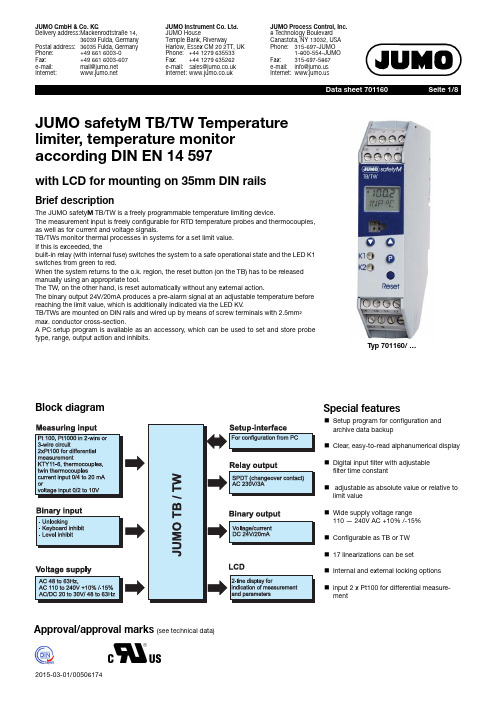
Seite 1/8JUMO GmbH & Co. KGDelivery address:Mackenrodtstraße 14,36039 Fulda, GermanyPostal address:36035 Fulda, Germany Phone:+49 661 6003-0Fax:+49 661 6003-607e-mail:*************Internet: JUMO Instrument Co. Ltd.JUMO HouseTemple Bank, RiverwayHarlow, Essex CM 20 2TT, UK Phone:+44 1279 635533Fax:+44 1279 635262e-mail:*************.uk Internet: JUMO Process Control, Inc.8 Technology Boulevard Canastota, NY 13032, USA Phone:315-697-JUMO1-800-554-JUMOFax:315-697-5867e-mail:************Internet:JUMO safetyM TB/TW Temperature limiter, temperature monitor according DIN EN 14597with LCD for mounting on 35mm DIN railsBrief descriptionThe JUMO safety M TB/TW is a freely programmable temperature limiting device.The measurement input is freely configurable for RTD temperature probes and thermocouples,as well as for current and voltage signals.TB/TWs monitor thermal processes in systems for a set limit value. If this is exceeded, thebuilt-in relay (with internal fuse) switches the system to a safe operational state and the LED K1switches from green to red.When the system returns to the o.k. region, the reset button (on the TB) has to be released manually using an appropriate tool.The TW, on the other hand, is reset automatically without any external action.The binary output 24V/20mA produces a pre-alarm signal at an adjustable temperature before reaching the limit value, which is additionally indicated via the LED KV .TB/TWs are mounted on DIN rails and wired up by means of screw terminals with 2.5mm²max. conductor cross-section.A PC setup program is available as an accessory, which can be used to set and store probe type, range, output action and inhibits.Block diagramTyp 701160/ …Special featuresk Setup program for configuration and archive data backup k Clear, easy-to-read alphanumerical display k Digital input filter with adjustable filter time constantk adjustable as absolute value or relative to limit value k Wide supply voltage range 110 — 240V AC +10% /-15%k Configurable as TB or TW k 17 linearizations can be setk Internal and external locking options k input 2 x Pt100 for differential measure-mentApproval/approval marks (see technical data)Technical dataAnalog inputsRTD temperature probethermocouplesDC voltage, DC currentMeasuring circuit monitoringDesignation Measuring range Accuracy 1Pt 100 EN 60751-200…+850°C 0.1%KTY11-6 PTC -50...150°C 1%Pt 1000 DIN -200…+850°C 0.1%connection types 2-wire, 3-wire circuits Sampling 210msInput filter 2nd order digital filter; filter constant adjustable from 0to 100secsSpecial features2x Pt100 for differential measurement, display can also be programmed in °FDesignationMeasuring range Accuracy 1Fe-CuNi "L" DIN 43710-200to +900°C 0.4%Fe-CuNi "J" EN 60584-200to +1200°C 0.4%Cu-CuNi "U" DIN 43710-200to +600°C 0.4%Cu-CuNi "T" EN 60584-200to +400°C 0.4%NiCr-Ni "K" EN 60584-200to +1372°C 0.4%NiCrSi-NiSi "N" EN 60584-100to +1300°C 0.4%Pt10Rh-Pt "S" EN 605840to +1768°C 0.4%Pt13Rh-Pt "R" EN 605840to +1768°C 0.4%Pt30Rh-Pt6Rh "B" EN 60584300to 1820°C 0.4%W3Re-W25Re "D"0...2495°C 0.4%Cold junctionPt 100, internal Cold junction accuracy ± 1K Sampling rate 210 msInput filter 2nd order digital filter; filter constant adjustable from 0to 100secs Special featuresalso programmable in °F1. Accuracy refers to the maximum extent of the measuring range. If the measuring range is smaller, the linearisation accuracy is reduced .Measuring rangeAccuracy 0to 20mA, voltage drop < 2 V 4to 20mA, voltage drop < 2 V 0.2%0to 10V , input resistance > 100 k Ω2to 10V , input resistance > 100 kW 0.1%Scaling freely programmable within the limits Sampling rate 210 msInput filter2nd order digital filter; filter constant adjustable from 0to 100secsRTD temperature probe and KTY11-6Twin thermocouplesThermocouplesCurrent 0 to 20 mA, 4 to 20mA Voltage 0 to 10 V , 2 to 10 VOverrange and un-derrange is detected LEDs K1 and KV light up; "1999" flashes in the displayProbe and lead break is detectedLEDs K1 and KV light up; "1999" flashes in the display; relay K1 is active.is detected at 4 to 20mA and 2 to 10VLEDs K1 and KV light up;"1999" flashes in the display Relay K1 is inactiveProbe short circuitis detectedLEDs K1 and KV light up;"1999" flashes in the display Relay K1 is inactiveis not detectedBinary inputRelay- and Binary outputVoltage supplyAapproval/MarksSwitching action at limit valueconnection Function1 floating contactConfigurable unlocking, keyboard inhibit, level inhibit1 relay100000 operations at a contact rating of:AC 230/24V; 3(0,5)A; cos φ=1 (≥ 0,6); 50Hz DC 24V; 3(0,5; τ=7ms)AUL60730AC230V; 3A D300; 30kAC/DC 24V; 3A, minimum current: DC 24V, 100mAContact protection circuit:safety fuse 3.15AT, installed in the pole contact arm within the instrument 1 Binary output24 V DC / 20mA logic signal, short-circuit proofvoltage supply 20 - 30V AC/DC, 48 ...63 Hz110V/240V AC, +10% /-15%Power consumption5 VAapproval marks Inspection authority Certificate/Inspection numbers inspection basics valid forDIN DIN CERTCOTW/TB 1206 08DIN EN 14597all instrument versions c UL usUnderwriters Laboratories 20091123-E325456UL 60730-2-9all instrument versionsSwitching action inverseSwitching action directSwitching action at differential measurementTest voltages to EN 60730, Part 1Between input or output and supply- at 110-240 V AC supply +10% /-15% 3.7kV/50Hz- at 20 - 30V AC/DC supply, 48 - 63 Hz 3.7kV/50HzElectrical safetyClearances / creep pathsMains to electronic components and probe≥6 mm / ≥8 mmMains to the relay≥6 mm / ≥8 mmRelay to electronic components and probe≥6 mm / ≥8 mmElectrical safety according to DIN EN 14597 (DIN EN 60730-2-9)Overvoltage category III, pollution degree 2Protection type I with internal separation to SELV current circuits Environmental influencesAmbient temperature range0...+55°CStorage temperature range-30...+70°CTemperature error≤ ± 0.005% / K dev. from 23°C1 for resistance thermometers≤ ± 0.01% / K dev. from 23°C1 for thermocouple, current, voltage Climatic conditions85% rel. humidity, no condensation(3K3 with extended temperature range to EN 60721)EMC to EN 14597 and standards from the EN 61326 series of standards Interference emission Class BInterference immunity Test level for safety, control and regulating instruments (RS) to EN 14597 1.All details refer to the full scale valueHousingMaterial polyamide (PA 6.6)Screw terminal0.2-2.5mm2 screw terminalMounting on 35mm x7.5mm DIN rail to EN 60715mounting position verticalWeight approx. 160gProtection type IP 20 to EN 60529DimensionsType 701160/...DIN-approved probes for operation in airNote: Because of the high response accuracy, the use of thermowell s (pockets) is not admi ss ible .Actual type de s ignationOld type de s ignationProbe typeTemperature rangeNom. length mmP roce ss connectionRTD temperature probe Data S heet 90.2006902006/65-228-1003-1-15-500-668/000- 1 x Pt100-170 ... +700°C500902006/65-228-1003-1-15-710-668/000-710902006/65-228-1003-1-15-1000-668/000-1000902006/55-228-1003-1-15-500-254/000- 1 x Pt100-170 ... +700°C500902006/55-228-1003-1-15-710-254/000-710902006/55-228-1003-1-15-1000-254/000-1000902006/65-228-2003-1-15-500-668/00090.271-F01 2 x Pt100-170 ... +700°C500Stop flange,movable902006/65-228-2003-1-15-710-668/00090.272-F01710902006/65-228-2003-1-15-1000-668/00090.273-F011000902006/55-228-2003-1-15-500-254/000- 2 x Pt100-170 ... +700°C500movableG1/2 compression clamp 902006/55-228-2003-1-15-710-254/000-710902006/55-228-2003-1-15-1000-254/000-1000Thermocouple s Data S heet 90.1006901006/65-547-2043-15-500-668/00090.019-F01 2 x NiCr-Ni, Typ E …K“-35 ... +800°C500Stop flange,movable901006/65-547-2043-15-710-668/00090.020-F01710901006/65-547-2043-15-1000-668/00090.021-F011000901006/65-546-2042-15-500-668/00090.019-F11 2 x Fe-CuNi, Typ E …L“-35 ... +700°C500901006/65-546-2042-15-710-668/00090.020-F11710901006/65-546-2042-15-1000-668/00090.021-F111000901006/66-550-2043-6-500-668/00090.023-F01 2 x NiCr-Ni, Typ E …K“-35 ... +1000°C500901006/66-550-2043-6-355-668/00090.023-F023********/66-550-2043-6-250-668/00090.023-F03250901006/66-880-1044-6-250-668/00090.021 1 x PT10Rh-PT, Typ E …S“0 ... 1300°C250901006/66-880-1044-6-355-668/00090.022*********/66-880-1044-6-500-668/00090.023*********/66-880-2044-6-250-668/00090-D-021 2 x PT10Rh-PT, Typ E …S“0 ... 1300°C250Stop flange,movable 901006/66-880-2044-6-355-668/00090-D-022*********/66-880-2044-6-500-668/00090-D-023500901006/66-953-1046-6-250-668/00090.027 1 x PT30Rh-PT6Rh, Typ E …B“600 ... 1500°C 250901006/66-953-1046-6-355-668/00090.028*********/66-953-1046-6-500-668/00090.029500901006/66-953-2046-6-250-668/00090-D-027 2 x PT30Rh-PT6Rh, Typ E …B“600 ... 1500°C 250901006/66-953-2046-6-355-668/00090-D-028*********/66-953-2046-6-500-668/00090-D-029500DIN-approved probes for operation in water and oilDIN-approved probes for operation in water and oilDIN-approved probes for operation air, water and oilNote: Because of the high response accuracy, the use of thermowell s (pockets) is not admi ss ible .Actual type de s ignationOld type de s ignationProbe typeTemperature rangeNom. length mmP roce ss connectionRTD temperature probe Data S heet 90.200690.2006/10-402-1003-1-9-100-104/000 1 x Pt100-40 ... +400°C100G1/2 screw connection90.2006/10-402-2003-1-9-100-104/000 2 x Pt100100902006/54-227-2003-1-15-710-254/00090.272-F02 2 x Pt100-170 ... 550°C 65...670movableG1/2 compression clamp 902006/54-227-1003-1-15-710-254/00090.272-F03 1 x Pt10065...670902006/10-226-1003-1-9-250-104/00090.239 1 x Pt100-170 ... 480°C 250G1/2 screw connection 902006/10-226-2003-1-9-250-104/00090-D-2392 x Pt100250Thermocouple s Data S heet 90.1006901006/54-544-2043-15-710-254/00090.020-F02 2 x NiCr-Ni, Type …K“-35 ... 550°C65...670movableG1/2 compression clamp901006/54-544-1043-15-710-254/00090.020-F03 1 x NiCr-Ni, Type …K“65...670901006/54-544-2042-15-710-254/00090.020-F12 2 x FeCuNi, Type …L“65...670901006/54-544-1042-15-710-254/00090.020-F131 x FeCuNi, Type …L“65 (670)Note: Because of the high response accuracy, the use of thermowell s (pockets) is not admi ss ible .Actual type de s ignationOld type de s ignationProbe typeTemperature rangeNom. length mmP roce ss connectionRTD temperature probe Data S heet 90.200690.2006/10-402-1003-1-9-100-104/000 1 x Pt100-40 ... +400°C100G1/2 screw connection90.2006/10-402-2003-1-9-100-104/000 2 x Pt100100902006/54-227-2003-1-15-710-254/00090.272-F02 2 x Pt100-170 ... 550°C 65...670movableG1/2 compression clamp 902006/54-227-1003-1-15-710-254/00090.272-F03 1 x Pt10065...670902006/10-226-1003-1-9-250-104/00090.239 1 x Pt100-170 ... 480°C 250G1/2 screw connection 902006/10-226-2003-1-9-250-104/00090-D-2392 x Pt100250Thermocouple s Data S heet 90.1006901006/54-544-2043-15-710-254/00090.020-F02 2 x NiCr-Ni, Type …K“-35 ... 550°C65...670movableG1/2 compression clamp901006/54-544-1043-15-710-254/00090.020-F03 1 x NiCr-Ni, Type …K“65...670901006/54-544-2042-15-710-254/00090.020-F12 2 x FeCuNi, Type …L“65...670901006/54-544-1042-15-710-254/00090.020-F131 x FeCuNi, Type …L“65 (670)Note: Because of the high response accuracy, the use of thermowell s (pockets) is not admi ss ible .Actual type de s ignationOld type de s ignationProbe typeTemperature rangeIn s tall. length mmP roce ss connectionRTD temperature probe Data S heet 90.200690.2006/10-390-1003-1-8-250-104/00090.210-F951 x Pt100max. 300°C250Thermocouple s Data S heet 90.1006901006/45-551-2043-2-xxxx-11-xxxx2 x NiCr-Ni, Typ E …K“max. 1 50°C50 (2000)Connection diagramOrder detailsScope of delivery1 JUMO safety M TB/TW in the ordered version1 Operating Instructions 701160.0Accessories Sales No.Setup Programm, multilingual 70/00514193 PC interface with TTL/RS232 converter and adapter (socket)70/00350260 PC interface with USB/TTL converter, adapter (socket) and adapter (pins)70/00456352 External reset button RT70/97097865。
版温湿度监控系统操作说明
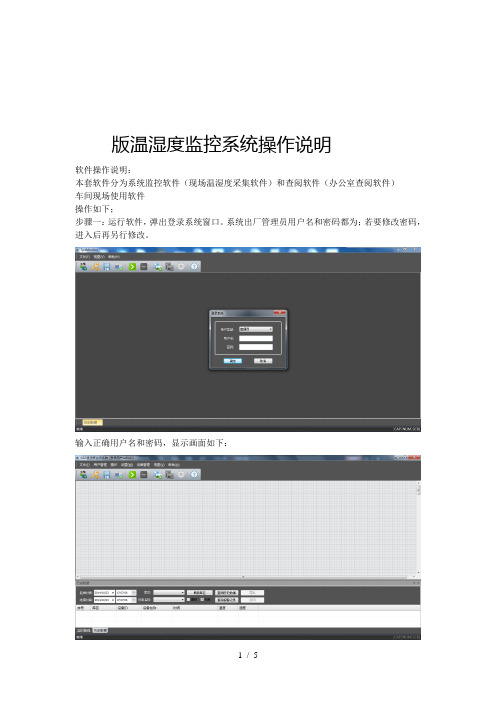
版温湿度监控系统操作说明软件操作说明:本套软件分为系统监控软件(现场温湿度采集软件)和查阅软件(办公室查阅软件)车间现场使用软件操作如下;步骤一:运行软件,弹出登录系统窗口。
系统出厂管理员用户名和密码都为;若要修改密码,进入后再另行修改。
输入正确用户名和密码,显示画面如下:在软件格子条纹框内,右键→新建设备,跳出如下设备属性输入框;注意事项:设备每个设备都不一样。
车间内如果有个探头,那么探头对应的应该为号。
每个部门的设备都是从号开始。
设备不可重复,依次新建设备。
设备类型(贵司类型均为)设备名称自行修改(对应探头地方) 显示在设备显示屏左上角第二个数字单通道设备全部设置为探头 不用输入双击设备,弹出下列属性框。
白色部分为可修改:保存间隔;设置成为,所有数据则是半个小时保存一次。
从开始采集开始算。
如果是中午:开始采集,数据就会:保存一组,:保存一组,一直到软件停止运行。
属性框设置温湿度上下限,超出范围,大屏上数值变红色,并一直显示超限设备数值。
按照各个库请自行设定好温湿度上下限。
修改好之后,请点击保存。
以上设置好之后,请点击保存配置文档,否则,下次打开软件,要重新输入设置通讯设置红色部分为,无线数据接收器接入端口,波特率为(固定为)蓝色部分为,数据备份到指定文件夹,可以选择,软件采集后,数据自动会存到文件夹中,电脑断电,数据会自动保存,不会丢失。
以上设置结束,点击开始采集。
打印数据步骤:视图→点击历史数据→选择起始时间和结束时间→刷新库区→库区选择所有库区→所有设备→点击列表→查询历史数据,点击打印,打印之前可以预览下,点数多,可以分纵向和横向打印;打印标题自行修改。
以上,如有疑问,联系说明归深圳市拓普瑞电子所有。
温湿度监控系统操作使用说明

温湿度监控系统操作使用说明一、系统简介温湿度监控系统是一种用来实时监测和记录环境温度和相对湿度变化的系统。
该系统通过传感器检测环境温湿度,并将数据传输到监控中心进行实时显示和记录。
系统具有高精度、高稳定性、易操作等特点,适用于各种场所和环境。
二、系统组成1.传感器:用于检测环境的温度和湿度。
2.集控器:接收传感器数据并传输到监控中心。
3.监控中心:显示和记录传感器数据,提供报警功能等。
三、系统安装1.传感器安装:选择合适的位置安装传感器,注意避免阳光直射、水汽等影响温湿度测量的因素。
传感器应固定牢固,避免震动和干扰。
2.集控器安装:将集控器与传感器通过正确的接口连接起来,确保连接稳定。
集控器应安装在通风良好、温度适宜的地方。
3.监控中心安装:安装监控中心软件并按照说明进行设置,确保能够与集控器通信。
四、系统操作1.开机操作:按照监控中心软件的指引启动系统,确保传感器和集控器正常连接,并显示传感器的温湿度数据。
2.数据监测:监控中心会实时显示传感器采集到的温湿度数据,包括当前数值、最高值、最低值等信息。
可以通过图表等形式进行查看和分析。
3.数据记录:系统会将传感器数据保存到数据库中,用户可通过查看历史数据来了解温湿度变化的趋势。
可以根据需要设置保存的时间间隔和记录的数量。
4.报警功能:监控中心可以设置温湿度的报警阈值,当传感器检测到温湿度超出设定的范围时会自动报警,提醒用户进行处理。
报警方式可以通过声音、弹窗、短信等形式进行设置。
5. 数据导出:系统可以将数据导出为Excel或其他格式的文件,方便用户进行数据分析和报表制作。
6.系统设置:监控中心提供一些系统参数的设置选项,用户可以根据需要进行调整,如显示单位、报警阈值、报警方式等。
五、系统维护1.定期校准:传感器的准确度会随着时间的变化而降低,建议定期对传感器进行校准,确保温湿度的测量结果准确可靠。
2.清洁保养:定期清洁传感器和集控器,保持设备的良好状态,避免尘埃或污物的积累对测量结果的影响。
温控说明书

温控说明书温控说明书1. 简介温控是指通过控制系统自动调整温度,以满足特定的需求和要求。
温控系统广泛应用于各种场合,例如家庭、工业、农业等领域。
本文档将介绍温控系统的工作原理、使用方法以及常见问题解决方案。
2. 工作原理温控系统通过一系列传感器、控制器和执行器组成。
传感器用于感知环境的温度变化,控制器根据传感器的反馈信息决定是否调整温度,执行器则负责根据控制器的指令进行温度调节。
具体来说,温控系统的工作流程如下:1. 传感器感知环境的温度变化,将温度数据发送给控制器。
2. 控制器根据预设的温度范围,比较传感器反馈的温度数据与设定值,决定是否需要进行调整。
3. 若需要调整温度,控制器通过执行器发出指令,例如打开或关闭加热器、冷凝器等设备。
4. 执行器根据控制器的指令进行相应操作,调节温度至设定值。
5. 传感器不断监测环境的温度变化,循环执行上述步骤以维持恒温状态。
3. 使用方法以下是使用温控系统的步骤:1. 了解温控系统的工作原理和组成部分。
2. 将传感器安装在需要监测的位置,确保其能够准确感知温度变化。
3. 连接传感器与控制器,并确保其正常工作。
4. 配置控制器的设定值,即期望的温度范围。
5. 启动温控系统,等待系统开始自动调节温度。
6. 监测温度变化,如有需要,可以根据实际情况调整设定值。
7. 定期检查温控系统的运行状态,确保各组件正常工作。
8. 如需更改系统配置或修复故障,可参考温控系统的说明书或联系售后服务。
4. 常见问题解决方案4.1 温度不稳定可能原因及解决方案:- 传感器位置选择不当:重新选择合适的位置安装传感器,避免外部干扰或局部温度差异。
- 控制器设定值不准确:根据实际需求,重新设置设定值。
- 执行器故障:检查执行器是否正常工作,如有必要,更换故障执行器。
4.2 温度超过设定范围可能原因及解决方案:- 传感器故障:检查传感器是否正常工作,如有必要,更换故障传感器。
- 控制器故障:检查控制器是否正常工作,如有必要,更换故障控制器。
温度记录仪使用手册
目录一、概述 (1)二、功能特点 (2)三、技术指标 (4)四、安装与接线及外形结构 (6)五、仪表运行及操作 (10)六、仪表参数设置及通讯协议 (23)七、软件使用说明 (31)八、故障分析与排除 (35)一、概述触控数据记录仪以其丰富的显示画面、灵活的操作方式以及强大的记录、运算、控制和管理功能,在各行各业中获得了极其广泛的应用。
本产品吸纳了各种国内外数据记录仪的优点,应用最新的显示技术、微电子技术、数据存储和通讯技术,是一款功能齐全、操作方便、精确可靠、高性价比的产品。
本产品在配置方面拥有蓝屏和彩色屏两种选择。
可以接收多种类型的电流、电压和电阻信号,实现温度、湿度、压力、液面、流量、成分以及力、力矩、位移等物理量的显示、记录、越限监控、报表生成、数据通讯、信号变送以及流量累计等功能。
本产品主要由触控液晶屏、按键、ARM微处理器为核心的主板、主电源、外供变送器电源、智能通道板、大容量FLASH等构成:可配备不同类型的智能通道板,根据应用要求选择。
内置大容量FLASH,可通过U盘快速将FLASH中的数据转储到计算机中。
内置的FLASH的容量为70M字节,8通道时若20秒记录一次可记录108天,最快1秒记录一次所有通道的数据。
数字显示界面、棒图显示画面、实时曲线画面、追忆曲线画面追忆曲线读数光标功能。
测量、显示基本误差:±0.2% F·S可参数设置多点报警功能。
二、功能特点本产品显示信息量大、界面友好、操作简单,下面是主要功能特点:不需要笔和纸记录,日常维护工作量非常小,运行费用低;采用高亮度触控彩色TFT液晶屏,CCFL背光、画面清晰;采用ARM微处理器,可同时实现多路(仪器内部最高64路)信号采集、记录、显示和报警;采用70MB 大容量的FLASH 闪存芯片存贮历史数据,掉电永不丢失数据;全隔离万能输入,可同时输入多种信号,无需更换模块,直接在仪器上设置即可;显示工程量数据的数值范围更宽可显示6位数值:-999,99~1999.99;可以进行参数设置、显示工程位号,工程单位,有流量累积;具有闪动报警显示,同时指示各路通道的下下限、下限、上限、上上限报警;8路继电器报警输出(订做产品);显示精度高,基本误差为±0.2% F·S;内置GB2312汉字库,使用全拼输入法输入;支持外接微型打印机,手动打印数据、曲线,自动定时打印数据,满足用户现场打印的需求(订做产品);配备标准USB2.0接口。
商业银行信息科技风险管理指引(银监发2009[1].19)
![商业银行信息科技风险管理指引(银监发2009[1].19)](https://img.taocdn.com/s3/m/23dd58669b6648d7c1c7460a.png)
--------------------------------------------------------------------------------商业银行信息科技风险管理指引第一章总则第一条为加强商业银行信息科技风险管理,根据《中华人民共和国银行业监督管理法》、《中华人民共和国商业银行法》、《中华人民共和国外资银行管理条例》,以及国家信息安全相关要求和有关法律法规,制定本指引。
第二条本指引适用于在中华人民共和国境内依法设立的法人商业银行。
政策性银行、农村合作银行、城市信用社、农村信用社、村镇银行、贷款公司、金融资产管理公司、信托公司、财务公司、金融租赁公司、汽车金融公司、货币经纪公司等其他银行业金融机构参照执行。
第三条本指引所称信息科技是指计算机、通信、微电子和软件工程等现代信息技术,在商业银行业务交易处理、经营管理和内部控制等方面的应用,并包括进行信息科技治理,建立完整的管理组织架构,制订完善的管理制度和流程。
第四条本指引所称信息科技风险,是指信息科技在商业银行运用过程中,由于自然因素、人为因素、技术漏洞和管理缺陷产生的操作、法律和声誉等风险。
第五条信息科技风险管理的目标是通过建立有效的机制,实现对商业银行信息科技风险的识别、计量、监测和控制,促进商业银行安全、持续、稳健运行,推动业务创新,提高信息技术使用水平,增强核心竞争力和可持续发展能力。
第二章信息科技治理第六条商业银行法定代表人是本机构信息科技风险管理的第一责任人,负责组织本指引的贯彻落实。
第七条商业银行的董事会应履行以下信息科技管理职责:(一)遵守并贯彻执行国家有关信息科技管理的法律、法规和技术标准,落实中国银行业监督管理委员会(以下简称银监会)相关监管要求。
(二)审查批准信息科技战略,确保其与银行的总体业务战略和重大策略相一致。
评估信息科技及其风险管理工作的总体效果和效率。
(三)掌握a主要的信息科技风险,确定可接受的风险级别,确保相关风险能够被识别、计量、监测和控制。
温度控制设备操作指南说明书

Field settings table[6.8.2] = .... ID66F2*BLQ05CAV3*DLQ05CAV3*BLQ07CAV3*DLQ07CAV3(*1)*B*(*2)*D*4P405542-1A - 2017.047.4.1.1R/W [3-07]~[3-06], step: A.3.2.421°C7.4.1.2R/W [3-07]~[3-06], step: A.3.2.419°C7.4.1.3R/W [3-08]~[3-09], step: A.3.2.424°C7.4.1.4R/W[3-08]~[3-09], step: A.3.2.426°C7.4.2.1[8-09]R/W [9-01]~[9-00], step: 1°C 45°C7.4.2.2[8-0A]R/W [9-01]~[9-00], step: 1°C 40°C7.4.2.3[8-07]R/W [9-03]~[9-02], step: 1°C 18°C7.4.2.4[8-08]R/W [9-03]~[9-02], step: 1°C 20°C7.4.2.5R/W -10~10°C, step: 1°C 0°C7.4.2.6R/W -10~10°C, step: 1°C -2°C7.4.2.7R/W -10~10°C, step: 1°C 0°C7.4.2.8R/W-10~10°C, step: 1°C 2°C7.4.3.1[6-0A]R/W 30~[6-0E]°C, step: 1°C 55°C7.4.3.2[6-0B]R/W 30~min(50, [6-0E])°C, step: 1°C 45°C7.4.3.3[6-0C]R/W30~min(50, [6-0E])°C, step: 1°C 45°C 7.4.4R/W0: Level 11: Level 22: Level 37.4.5.1[C-0C][D-0C]R/W 0,00~990/kWh 0/kWh7.4.5.2[C-0D][D-0D]R/W 0,00~990/kWh 0/kWh7.4.5.3[C-0E][D-0E]R/W0,00~990/kWh 0/kWh 7.4.6R/W0,00~990/kWh 0,00~290/MBtu 8,0/kWh7.7.1.1[1-00]Set weather-dependent heating Low ambient temp. for LWT main zone heatingWD curve.R/W -40~5°C, step: 1°C-10°C7.7.1.1[1-01]Set weather-dependent heating High ambient temp. for LWT main zone heatingWD curve.R/W 10~25°C, step: 1°C 15°C7.7.1.1[1-02]Set weather-dependent heating Leaving water value for low ambient temp. forLWT main zone heating WD curve.R/W [9-01]~[9-00]°C, step: 1°C 45°C7.7.1.1[1-03]Set weather-dependent heating Leaving water value for high ambient temp. forLWT main zone heating WD curve.R/W[9-01]~min(45, [9-00])°C , step: 1°C 35°C7.7.1.2[1-06]Set weather-dependent cooling Low ambient temp. for LWT main zone coolingWD curve.R/W 10~25°C, step: 1°C 20°C7.7.1.2[1-07]Set weather-dependent cooling High ambient temp. for LWT main zone coolingWD curve.R/W 25~43°C, step: 1°C 35°C7.7.1.2[1-08]Set weather-dependent cooling Leaving water value for low ambient temp. forLWT main zone cooling WD curve.R/W [9-03]~[9-02]°C, step: 1°C 22°C7.7.1.2[1-09]Set weather-dependent cooling Leaving water value for high ambient temp. forLWT main zone cooling WD curve.R/W[9-03]~[9-02]°C, step: 1°C 18°C7.7.2.1[0-00]Set weather-dependent heating Leaving water value for high ambient temp. forLWT add zone heating WD curve.R/W [9-05]~min(45,[9-06])°C, step: 1°C 35°C7.7.2.1[0-01]Set weather-dependent heating Leaving water value for low ambient temp. forLWT add zone heating WD curve.R/W [9-05]~[9-06]°C, step: 1°C 45°C7.7.2.1[0-02]Set weather-dependent heating High ambient temp. for LWT add zone heatingWD curve.R/W 10~25°C, step: 1°C 15°C7.7.2.1[0-03]Set weather-dependent heating Low ambient temp. for LWT add zone heatingWD curve.R/W-40~5°C, step: 1°C -10°C7.7.2.2[0-04]Set weather-dependent cooling Leaving water value for high ambient temp. forLWT add zone cooling WD curve.R/W [9-07]~[9-08]°C, step: 1°C 8°C7.7.2.2[0-05]Set weather-dependent cooling Leaving water value for low ambient temp. forLWT add zone cooling WD curve.R/W [9-07]~[9-08]°C, step: 1°C 12°C7.7.2.2[0-06]Set weather-dependent cooling High ambient temp. for LWT add zone coolingWD curve.R/W 25~43°C, step: 1°C 35°C7.7.2.2[0-07]Set weather-dependent cooling Low ambient temp. for LWT add zone coolingWD curve.R/W10~25°C, step: 1°C 20°CA.2.1.1[E-00]R/O 0~52: Monobloc A.2.1.2[E-01]R/O 0~10: 8A.2.1.3[E-02]R/O 0: Type 1 (*1)1: Type 2 (*2)A.2.1.7[C-07]R/W0: LWT control 1: Ext RT control 2: RT control A.2.1.8[7-02]R/W 0: 1 LWT zone 1: 2 LWT zones A.2.1.9[F-0D]R/W0: Continuous 1: Sample 2: Request A.2.1.A [E-04]R/O0: No 1: YesIndoor software type Unit control methodNumber of LWT zones Pump operation modePower saving possible HighMedium Low Unit type Compressor type Comfort (cooling)Eco (cooling)Storage comfortStorage eco Reheat Comfort (heating)Eco (heating)Comfort (cooling)Eco (cooling)Comfort (heating)Eco (heating)Comfort (heating)Eco (heating)Comfort (cooling)Eco (cooling) 4P405542-1A - 2017.04(*1) *B*_(*2) *D*A.2.1.B R/W 0: At unit 1: In room A.2.1.C[E-0D]Glycol present R/W0: No 1: YesA.2.2.A [D-02]R/W0: No1: Secondary rtrn 2: Disinf. Shunt 3: Circul. Pump 4: CP & disinf. Sh A.2.2.B [C-08]R/W0: No1: Outdoor sensor 2: Room sensor A.2.2.E.1[E-03]R/W0: No BUH 1: 1 step 2: 2 steps A.2.2.E.2[5-0D]R/W0~51: 1P,(1/1+2)4: 3PN,(1/2)5: 3PN,(1/1+2)A.2.2.E.3[D-01]R/W0: No1: Open tariff 2: Closed tariff A.2.2.E.4[E-05]R/W 0: No 1: YesA.2.2.E.5[C-05]R/W 1: Thermo ON/OFF 2: C/H request A.2.2.E.6[C-06]R/W0~21: Thermo ON/OFF A.2.2.F.1[C-02]R/W0: No1: Bivalent 2: -3: -A.2.2.F.2[C-09]R/W 0: Normally open 1: Normally closed A.2.2.F.3[D-08]R/W0: No1: 0,1 pulse/kWh 2: 1 pulse/kWh 3: 10 pulse/kWh 4: 100 pulse/kWh 5: 1000 pulse/kWh A.2.2.F.4[D-09]R/W0: No1: 0,1 pulse/kWh 2: 1 pulse/kWh 3: 10 pulse/kWh 4: 100 pulse/kWh 5: 1000 pulse/kWh A.2.2.F.5[C-08]R/W0: No1: Outdoor sensor 2: Room sensor A.2.2.F.6[D-04]R/W0: No 1: YesA.2.3.1[6-02]R/W 0~10kW, step: 0,2kW 3kWA.2.3.2[6-03]R/W 0~10kW, step: 0,2kW 3kWA.2.3.3[6-04]R/W0~10kW, step: 0,2kW 0kWA.3.1.1.1R/W0: Fixed1: Weather dep.2: Fixed + scheduled 3: WD + scheduled A.3.1.1.2.1[9-01]Temperature range Minimum temp (heating)R/W 15~37°C, step: 1°C 25°CA.3.1.1.2.2[9-00]Temperature range Maximum temp (heating)R/W 37~55°C, step: 1°C 55°CA.3.1.1.2.3[9-03]Temperature range Minimum temp (cooling)R/W 5~18°C, step: 1°C 5°CA.3.1.1.2.4[9-02]Temperature range Maximum temp (cooling)R/W 18~22°C, step: 1°C 22°C A.3.1.1.5[8-05]R/W 0: No 1: Yes A.3.1.1.7[9-0B]R/W0: Quick 1: SlowA.3.1.2.1R/W0: Fixed1: Weather dep.2: Fixed + scheduled 3: WD + scheduled A.3.1.2.2.1[9-05]Temperature range Minimum temp (heating)R/W 15~37°C, step: 1°C 25°CA.3.1.2.2.2[9-06]Temperature range Maximum temp (heating)R/W 37~55°C, step: 1°C 55°CA.3.1.2.2.3[9-07]Temperature range Minimum temp (cooling)R/W 5~18°C, step: 1°C 5°CA.3.1.2.2.4[9-08]Temperature rangeMaximum temp (cooling)R/W18~22°C, step: 1°C 22°CA.3.1.3.1[9-09]R/W 3~10°C, step: 1°C 5°CA.3.1.3.2[9-0A]R/W3~10°C, step: 1°C 5°CA.3.2.1.1[3-07]Room temp. rangeMinimum temp (heating)R/W 12~18°C, step: A.3.2.416°CA.3.2.1.2[3-06]Room temp. range Maximum temp (heating)R/W 18~30°C, step: A.3.2.430°CA.3.2.1.3[3-09]Room temp. range Minimum temp (cooling)R/W 15~25°C, step: A.3.2.415°CA.3.2.1.4[3-08]Room temp. rangeMaximum temp (cooling)R/W25~35°C, step: A.3.2.435°CExternal kWh meter 1External kWh meter 2External sensor PCC by digital inputs Backup heater stepsBUH type Preferential kWh rate DHW operation Contact type main Contact type add.BUH: step 1BUH: step 2LWT setpoint modeModulated LWT Emitter typeLWT setpoint modeHeating CoolingUser interface location DHW pumpExternal sensor Booster heaterExt. backup heat srcAlarm output (*1) *B*_(*2) *D* 4P405542-1A - 2017.04A.3.2.2[2-0A]R/W -5~5°C, step: 0,5°C 0°CA.3.2.3[2-09]R/W -5~5°C, step: 0,5°C 0°CA.3.2.4R/W0: 0,5 °C 1: 1 °CA.3.3.1[4-02]R/W 14~35 °C, step: 1°C 25°CA.3.3.2[F-01]R/W10~35°C, step: 1°C 20°CA.4.1[6-0D]R/W0: Reheat only1: Reheat + sched.2: Scheduled only A.4.4.1[2-01]R/W 0: No 1: YesA.4.4.2[2-00]R/W0: Each day 1: Monday 2: Tuesday 3: Wednesday 4: Thursday 5: Friday 6: Saturday 7: SundayA.4.4.3[2-02]R/W 0~23 hour, step: 1 hour 23A.4.4.4[2-03]R/W 55~80°C, step: 5°C 70°CA.4.4.5[2-04]R/W5~60 min, step: 5 min 10 minA.4.5[6-0E]R/W40~80°C, step: 1°C 60°CA.4.6R/W0: Fixed1: Weather dep.A.4.7[0-0B]Weather-dependent curveLeaving water value for high ambient temp. for DHW WD curve.R/W 35~[6-0E]°C, step: 1°C 55°CA.4.7[0-0C]Weather-dependent curve Leaving water value for low ambient temp. for DHW WD curve.R/W 45~[6-0E]°C, step: 1°C 60°CA.4.7[0-0D]Weather-dependent curve High ambient temp. for DHW WD curve.R/W 10~25°C, step: 1°C 15°CA.4.7[0-0E]Weather-dependent curveLow ambient temp. for DHW WD curve.R/W-40~5°C, step: 1°C -10°CA.5.1.1[4-00]R/W0~20: Disabled 1: Enabled A.5.1.3[4-07]R/W 0: No 1: YesA.5.1.4[5-01]R/W-15~35°C, step: 1°C -4°CA.6.1[3-00]R/W0: No 1: Yes A.6.2.1[D-00]R/W0: None 1: BSH only 2: BUH only 3: All heaters A.6.2.2[D-05]R/W0: Forced off 1: As normalA.6.3.1[4-08]R/W0: No limitation 1: Continuous 2: Digital inputs A.6.3.2[4-09]R/W 0: Current 1: PowerA.6.3.3[5-05]R/W 0~50 A, step: 1 A 50 AA.6.3.4[5-09]R/W 0~20 kW, step: 0,5 kW 20 kWA.6.3.5.1[5-05]Amp. limits for DI Limit DI1R/W 0~50 A, step: 1 A 50 AA.6.3.5.2[5-06]Amp. limits for DI Limit DI2R/W 0~50 A, step: 1 A 50 AA.6.3.5.3[5-07]Amp. limits for DI Limit DI3R/W 0~50 A, step: 1 A 50 AA.6.3.5.4[5-08]Amp. limits for DI Limit DI4R/W 0~50 A, step: 1 A 50 AA.6.3.6.1[5-09]kW limits for DI Limit DI1R/W 0~20 kW, step: 0,5 kW 20 kWA.6.3.6.2[5-0A]kW limits for DI Limit DI2R/W 0~20 kW, step: 0,5 kW 20 kWA.6.3.6.3[5-0B]kW limits for DI Limit DI3R/W 0~20 kW, step: 0,5 kW 20 kWA.6.3.6.4[5-0C]kW limits for DI Limit DI4R/W 0~20 kW, step: 0,5 kW 20 kW A.6.3.7[4-01]R/W0: None 1: BSH 2: BUHA.6.4[1-0A]R/W0: No averaging 1: 12 hours 2: 24 hours 3: 48 hours 4: 72 hours A.6.5[2-0B]R/W-5~5°C, step: 0,5°C 0°CType Amp. value kW value PriorityEnable BUH step 2Equilibrium temp.Allowed heatersForced pump OFF ModeTemperature target DurationOperation mode Ext. room sensor offset Space heating OFF tempDisinfectionOperation dayStart timeRoom temp. step Space cooling On tempRoom temp. offset 4P405542-1A - 2017.04(*1) *B*_(*2) *D*A.6.A[7-05]R/W0: Very high 1: High 2: Medium 3: Low 4: Very low A.6.CR/W0: Manual 1: AutomaticA.8[0-00]R/W [9-05]~min(45,[9-06])°C, step: 1°C 35°CA.8[0-01]R/W [9-05]~[9-06]°C, step: 1°C 45°CA.8[0-02]R/W 10~25°C, step: 1°C 15°CA.8[0-03]R/W -40~5°C, step: 1°C -10°CA.8[0-04]R/W [9-07]~[9-08]°C, step: 1°C 8°CA.8[0-05]R/W [9-07]~[9-08]°C, step: 1°C 12°CA.8[0-06]R/W 25~43°C, step: 1°C 35°CA.8[0-07]R/W 10~25°C, step: 1°C 20°CA.8[0-0B]R/W 35~[6-0E]°C, step: 1°C 55°CA.8[0-0C]R/W 45~[6-0E]°C, step: 1°C 60°CA.8[0-0D]R/W 10~25°C, step: 1°C 15°CA.8[0-0E]R/W -40~5°C, step: 1°C -10°CA.8[1-00]R/W -40~5°C, step: 1°C -10°CA.8[1-01]R/W 10~25°C, step: 1°C 15°CA.8[1-02]R/W [9-01]~[9-00], step: 1°C 45°CA.8[1-03]R/W [9-01]~min(45, [9-00])°C , step: 1°C 35°CA.8[1-04]R/W 0: Disabled 1: Enabled A.8[1-05]R/W 0: Disabled 1: EnabledA.8[1-06]R/W 10~25°C, step: 1°C 20°CA.8[1-07]R/W 25~43°C, step: 1°C 35°CA.8[1-08]R/W [9-03]~[9-02]°C, step: 1°C 22°CA.8[1-09]R/W [9-03]~[9-02]°C, step: 1°C 18°CA.8[1-0A]R/W0: No averaging 1: 12 hours 2: 24 hours 3: 48 hours 4: 72 hours A.8[2-00]R/W0: Each day 1: Monday 2: Tuesday 3: Wednesday 4: Thursday 5: Friday 6: Saturday 7: Sunday A.8[2-01]R/W 0: No 1: YesA.8[2-02]R/W 0~23 hour, step: 1 hour 23A.8[2-03]R/W 55~80°C, step: 5°C 70°CA.8[2-04]R/W 5~60 min, step: 5 min 10 minA.8[2-05]R/W 4~16°C, step: 1°C 16°CA.8[2-06]R/W 0: Disabled 1: EnabledA.8[2-09]R/W -5~5°C, step: 0,5°C 0°CA.8[2-0A]R/W -5~5°C, step: 0,5°C 0°CA.8[2-0B]R/W -5~5°C, step: 0,5°C 0°C A.8[3-00]R/W0: No 1: Yes A.8[3-01]0A.8[3-02]1A.8[3-03]4A.8[3-04]2A.8[3-05]1A.8[3-06]R/W 18~30°C, step: A.3.2.430°CA.8[3-07]R/W 12~18°C, step: A.3.2.416°CA.8[3-08]R/W 25~35°C, step: A.3.2.435°CA.8[3-09]R/W 15~25°C, step: A.3.2.415°C A.8[4-00]R/W0~20: Disabled 1: Enabled A.8[4-01]R/W0: None 1: BSH 2: BUHA.8[4-02]R/W14~35°C, step: 1°C 25°CWhat is the maximum desired room temperature in cooling?What is the minimum desired room temperature in cooling?What is the BUH operation mode?Which electric heater has priority?--------What is the maximum desired room temperature in heating?What is the mimimum desired room temperature in heating?Room frost protectionAdjust the offset on the measured room temperature Adjust the offset on the measured room temperature What is the required offset on the measured outdoor temp.?Is auto restart of the unit allowed?--When should the disinfection function be executed?Should the disinfection function be executed?When should the disinfection function start?What is the disinfection target temperature?How long must the tank temperature be maintained?Room antifrost temperature Weather dependent cooling of the additional leaving water temperature zone Low ambient temp. for LWT main zone cooling WD curve.High ambient temp. for LWT main zone cooling WD curve.Leaving water value for low ambient temp. for LWT main zone cooling WD curve.Leaving water value for high ambient temp. for LWT main zone cooling WD curve.What is the averaging time for the outdoor temp?Low ambient temp. for DHW WD curve.Low ambient temp. for LWT main zone heating WD curve.High ambient temp. for LWT main zone heating WD curve.Leaving water value for low ambient temp. for LWT main zone heating WD curve.Leaving water value for high ambient temp. for LWT main zone heating WD curve.Weather dependent cooling of the main leaving water temperature zone.Leaving water value for low ambient temp. for LWT add zone cooling WD curve.High ambient temp. for LWT add zone cooling WD curve.Low ambient temp. for LWT add zone cooling WD curve.Leaving water value for high ambient temp. for DHW WD curve.Leaving water value for low ambient temp. for DHW WD curve.High ambient temp. for DHW WD curve.Leaving water value for high ambient temp. for LWT add zone heating WD curve.Leaving water value for low ambient temp. for LWT add zone heating WD curve.High ambient temp. for LWT add zone heating WD curve.Low ambient temp. for LWT add zone heating WD curve.Leaving water value for high ambient temp. for LWT add zone cooling WD curve.Below which outdoor temperature is heating allowed?(*1) *B*_(*2) *D* 4P405542-1A - 2017.04A.8[4-03]R/W0: Limited 1: No limit2: Most optimum 3: Optimum4: Only legionellaA.8[4-04]R/W0: Continuous pump operation 1: Intermittent pump operation 2: No protection A.8[4-05]0A.8[4-06]0/1A.8[4-07]R/W 0: No 1: YesA.8[4-08]R/W0: No limitation 1: Continuous 2: Digital inputs A.8[4-09]R/W0: Current 1: Power A.8[4-0A]0A.8[4-0B]R/W 1~10°C, step: 0,5°C 1°CA.8[4-0D]R/W 1~10°C, step: 0,5°C 3°C A.8[4-0E]Is the installer on site?R/W 0: No 1: Yes A.8[5-00]R/W 0: Allowed1: Not allowedA.8[5-01]R/W -15~35°C, step: 1°C -4°CA.8[5-02]R/W 0: Disabled 1: EnabledA.8[5-03]R/W -15~35°C, step: 1°C 0°CA.8[5-04]R/W 0~20°C, step: 1°C 10°CA.8[5-05]R/W 0~50 A, step: 1 A 50 AA.8[5-06]R/W 0~50 A, step: 1 A 50 AA.8[5-07]R/W 0~50 A, step: 1 A 50 AA.8[5-08]R/W 0~50 A, step: 1 A 50 AA.8[5-09]R/W 0~20 kW, step: 0,5 kW 20 kWA.8[5-0A]R/W 0~20 kW, step: 0,5 kW 20 kWA.8[5-0B]R/W 0~20 kW, step: 0,5 kW 20 kWA.8[5-0C]R/W 0~20 kW, step: 0,5 kW 20 kW A.8[5-0D]R/W0~51: 1P,(1/1+2)4: 3PN,(1/2)5: 3PN,(1/1+2)A.8[5-0E]1A.8[6-00]R/W 2~20°C, step: 1°C 2°CA.8[6-01]R/W 0~10°C, step: 1°C 2°CA.8[6-02]R/W 0~10kW, step: 0,2kW 3kWA.8[6-03]R/W 0~10kW, step: 0,2kW 3kWA.8[6-04]R/W0~10kW, step: 0,2kW 0kW A.8[6-05]0A.8[6-06]0A.8[6-07]0A.8[6-08]R/W2~20°C, step: 1°C 10°C A.8[6-09]0A.8[6-0A]R/W 30~[6-0E]°C, step: 1°C 55°CA.8[6-0B]R/W 30~min(50, [6-0E])°C, step: 1°C 45°CA.8[6-0C]R/W 30~min(50, [6-0E])°C, step: 1°C 45°CA.8[6-0D]R/W0: Reheat only1: Reheat + sched.2: Scheduled only A.8[6-0E]R/W 40~80°C, step: 1°C 60°CA.8[7-00]R/W 0~4°C, step: 1°C 0°CA.8[7-01]R/W 2~40°C, step: 1°C 2°CA.8[7-02]R/W0: 1 LWT zone 1: 2 LWT zones A.8[7-03]2,5A.8[7-04]0A.8[7-05]R/W0: Very high 1: High 2: Medium 3: Low 4: Very low A.8[8-00] 1 minA.8[8-01]R/W 5~95 min, step: 5 min 30 minA.8[8-02]R/W 0~10 hour, step: 0,5 hour 3 hourA.8[8-03]R/W 20~95 min, step: 5 min 50 minA.8[8-04]R/W 0~95 min, step: 5 min 95 min A.8[8-05]R/W 0: No 1: YesA.8[8-06]R/W0~10°C, step: 1°C 3°CAdditional running time for the maximum running time.Allow modulation of the LWT to control the room temp?Leaving water temperature maximum modulation.--Boiler efficiency--Maximum running time for domestic hot water operation.Anti-recycling time.Booster heater delay timer.What is the desired DHW production type?What is the maximum temperature setpoint?Domestic hot water booster heater overshoot temperature.Domestic hot water booster heater hysteresis.How many leaving water temperature zones are there?----What is the hysteresis to be used in reheat mode?--What is the desired comfort storage temperature?What is the desired eco storage temperature?What is the desired reheat temperature?The temperature difference determining the heat pump OFF temperature.What is the capacity of the booster heater?What is the capacity of the backup heater step 1?What is the capacity of the backup heater step 2?----What is the requested limit for DI2?What is the requested limit for DI3?What is the requested limit for DI4?What type of backup heater installation is used?--The temperature difference determining the heat pump ON temperature.Set point correction for domestic hot water temperature.What is the requested limit for DI1?What is the requested limit for DI2?What is the requested limit for DI3?What is the requested limit for DI4?What is the requested limit for DI1?Automatic cooling/heating changeover hysteresis.Automatic cooling/heating changeover offset.Is backup heater operation allowed above equilibrium temperature during space heating operation?What is the equilibrium temperature for the building?Space heating priority.Space heating priority temperature.---- (Do not change this value)Enable the second step of the backup heater?Which power limitation mode is required on the system?Which power limitation type is required?--Operation permission of the booster heater.How to protect the water pipes from freezing 4P405542-1A - 2017.04(*1) *B*_(*2) *D*A.8[8-07]R/W [9-03]~[9-02], step: 1°C 18°CA.8[8-08]R/W [9-03]~[9-02], step: 1°C 20°CA.8[8-09]R/W [9-01]~[9-00], step: 1°C 45°CA.8[8-0A]R/W[9-01]~[9-00], step: 1°C 40°C A.8[8-0B]13A.8[8-0C]10A.8[8-0D]16A.8[9-00]R/W 37~55°C, step: 1°C 55°CA.8[9-01]R/W 15~37°C, step: 1°C 25°CA.8[9-02]R/W 18~22°C, step: 1°C 22°CA.8[9-03]R/W 5~18°C, step: 1°C 5°CA.8[9-04]R/W 1~4°C, step: 1°C 1°CA.8[9-05]R/W 15~37°C, step: 1°C 25°CA.8[9-06]R/W 37~55°C, step: 1°C 55°CA.8[9-07]R/W 5~18°C, step: 1°C 5°CA.8[9-08]R/W 18~22°C, step: 1°C 22°CA.8[9-09]R/W 3~10°C, step: 1°C 5°CA.8[9-0A]R/W 3~10°C, step: 1°C 5°CA.8[9-0B]R/W 0: Quick 1: SlowA.8[9-0C]R/W 1~6°C, step: 0,5°C 1 °CA.8[9-0D]R/W0~8, step:10 : 100%1~4 : 80~50%5~8 : 80~50%6A.8[9-0E]6A.8[A-00]0A.8[A-01]0A.8[A-02]0A.8[A-03]0A.8[A-04]0A.8[B-00]0A.8[B-01]0A.8[B-02]0A.8[B-03]0A.8[B-04]0A.8[C-00]0A.8[C-01]0A.8[C-02]R/W0: No1: Bivalent 2: -3: -A.8[C-03]R/W -25~25°C, step: 1°C 0°CA.8[C-04]R/W 2~10°C, step: 1°C 3°CA.8[C-05]R/W 1: Thermo ON/OFF 2: C/H request A.8[C-06]R/W0~20: -1: Thermo ON/OFF A.8[C-07]R/W0: LWT control 1: Ext RT control 2: RT control A.8[C-08]R/W0: No1: Outdoor sensor 2: Room sensor A.8[C-09]R/W0: Normally open 1: Normally closed A.8[C-0A]0A.8[C-0C]R/W 0~70A.8[C-0D]R/W 0~70A.8[C-0E]R/W 0~70A.8[D-00]R/W0: None 1: BSH only 2: BUH only 3: All heaters A.8[D-01]R/W0~30: No1: Open tariff 2: Closed tariff A.8[D-02]R/W0: No1: Secondary rtrn 2: Disinf. Shunt 3: Circul. Pump 4: CP & disinf. Sh A.8[D-03]R/W0: Disabled1: Enabled, shift 2°C (from -2 to 2°C)2: Enabled, shift 4°C (from -2 to 2°C)3: Enabled, shift 2°C (from -4 to 4°C)4: Enabled, shift 4°C (from -4 to 4°C)A.8[D-04]R/W 0: No 1: YesA.8[D-05]R/W0: Forced off 1: As normal A.8[D-07]Forced off contact type Is the pump allowed to run if prefer. kWh rate PS is cut?--Low electricity price decimal (Do not use)Which heaters are permitted if prefer. kWh rate PS is cut?Which type of DHW pump is installed?Leaving water temperature compensation around 0°C.Is the option box used for PCC ?What is the unit control method in space operation?Which type of external sensor is installed?What is the required alarm output contact type?--High electricity price decimal (Do not use)Medium electricity price decimal (Do not use)--Is an external backup heat source connected?Bivalent activation temperature.Bivalent hysteresis temperature.What is the thermo request contact type for the main zone?What is the thermo request contact type for the add. zone?------------------------What is the maximum desired LWT for add. zone in cooling?What is the desired delta T in heating?What is the desired delta T in cooling?What emitter type is connected to the main LWT zone?Room temperature hysteresis.Pump speed limitationWhat is the maximum desired LWT for main zone in cooling?What is the mimimum desired LWT for main zone in cooling?Leaving water temperature overshoot temperature.What is the mimimum desired LWT for add. zone in heating?What is the maximum desired LWT for add. zone in heating?What is the mimimum desired LWT for add. zone in cooling?What is the desired eco main LWT in heating?------What is the maximum desired LWT for main zone in heating?What is the mimimum desired LWT for main zone in heating?What is the desired comfort main LWT in cooling?What is the desired eco main LWT in cooling?What is the desired comfort main LWT in heating?(*1) *B*_(*2) *D* 4P405542-1A - 2017.04A.8[D-08]R/W0: No1: 0,1 pulse/kWh 2: 1 pulse/kWh 3: 10 pulse/kWh 4: 100 pulse/kWh 5: 1000 pulse/kWh A.8[D-09]R/W0: No1: 0,1 pulse/kWh 2: 1 pulse/kWh 3: 10 pulse/kWh 4: 100 pulse/kWh 5: 1000 pulse/kWh A.8[D-0A]0A.8[D-0B]2A.8[D-0C]R/W 0~490A.8[D-0D]R/W 0~490A.8[D-0E]R/W 0~490A.8[E-00]R/O 0~52: Monobloc A.8[E-01]R/O 0~10: 8A.8[E-02]R/O 0: Type 1 (*1)1: Type 2 (*2)A.8[E-03]R/W0: No BUH 1: 1 step 2: 2 steps A.8[E-04]R/O 0: No 1: Yes A.8[E-05]R/W0: No 1: Yes A.8[E-06]1A.8[E-07]0A.8[E-08]R/W0: Disabled 1: Enabled A.8[E-09]0A.8[E-0A]0A.8[E-0B]0A.8[E-0C]0A.8[E-0D]Is the system filled with glycol ?R/W 0: No 1: YesA.8[F-00]R/W 0: Disabled 1: EnabledA.8[F-01]R/W10~35°C, step: 1°C 20°C A.8[F-02]3A.8[F-03]5A.8[F-04]0A.8[F-05]0A.8[F-06]0A.8[F-09]R/W0: Disabled 1: Enabled A.8[F-0A]0A.8[F-0B]0A.8[F-0C]1A.8[F-0D]R/W0: Continuous 1: Sample 2: Request--Above which outdoor temperature is cooling allowed?What is the number of backup heater steps?Is the power saving function available on the outdoor unit?Can the system prepare domestic hot water?--------Pump operation during flow abnormality.--------Pump operation allowed outside range.What is the pump operation mode?----------Power saving function for outdoor unit.What is the high electricity price (Do not use)What is the medium electricity price (Do not use)What is the low electricity price (Do not use)Which type of unit is installed?Which type of compressor is installed?What is the indoor unit software type?Is an external kWh meter used for power measurement?Is an external kWh meter used for power measurement?---- 4P405542-1A - 2017.04(*1) *B*_(*2) *D*。
无线温湿度智能监测系统软件使用说明书(1)
无线温湿度智能监测系统软件使用说明书(V1.1)目录1系统概述 (1)1.1系统组成 (1)1.2节点概述 (1)2 软件运行环境 (2)2.1 软件环境 (2)2.2 硬件环境 (2)3 系统软件使用和操作 (3)3.1 安装QF03-A103总控端驱动驱动 (3)3.2 安装监测软件 (5)3.4卸载监测软件 (6)3.3 运行监测软件 (6)4注意事项 (10)5保管存放 (11)1系统概述1.1系统组成无线温湿度智能监测系统采用低功耗设计,具有体积小、节能、安全、安装简单、工作稳定等优点,是一个低成本、高性能、可常年不间断运行的无线传感网络系统,维护简单,使用方便。
无线温湿度采集终端能够任意安装在所需监测的地方,适合应用于需监测的军事区域、仓库、血液中心血库、厂房、机房、孵房、温室等对环境温湿度要求高的场合。
无线温湿度智能监测系统由若干无线温湿度采集终端、无线路由节点、一个总控端和监测中心监测管理软件组成。
系统总体结构如图1所示。
图1 无线温湿度智能监测系统拓扑结构1.2节点概述(1) 无线温湿度采集终端采集终端是两节1.5V普通干电池供电的低功耗的传感器节点,置于所测环境中进行温湿度数据的采集和预处理,并将数据上传给路由节点或总控端,呈星形拓扑结构排列,安装实施相对简单,可以节省费用,控制成本,具有很大的环境适应性。
用电池供电,能够工作一年以上。
任何采集终端在网络覆盖范围内可以自动加入或退出网络,且无需设置自动入网。
安装使用:安装方式,根据现场实际可以采用摆放、螺丝固定等方式。
采集终端要布置在无线路由或者总控端周围通信距离可视范围之内,采集终端周围应避免有大面积金属遮挡物。
在监测特别重要和密集的区域可以多放置几个采集终端。
(2) 路由节点路由节点负责整个网络的数据中继、覆盖延伸功能。
路由节点之间呈Mesh网状网络拓扑结构,其路由可自动建立和维护,具有强大的功能;网络可以通过“多级跳”的方式通信;组成极为复杂的网络;具备自组织、自愈功能。
温度在线监测仪产品手册

10) 湿度测量精度:±3.0%RH
11) 触头/电缆搭接头测温范围:-55℃~+125℃
12) 温度测量精度: ±0.1℃
13) 响应时间:≤1s
14) 人体接近感应时间:≤3 秒
15) 人体接近语音提示时间:0~29 秒
16) 开关量输入端子和 LED 数码显示关联关系:动态配置
1、本地化服务
2、强大的服务队伍和服务体系
3、完善的备件库
二、培训计划
三、售后服务计划
1、电话支持服务
2、现场支持服务
3、设备维修服务
4、设备更换服务
5、区域经理服务
6、投诉受理服务
2)、技术指标
1) 工作温度:-40~+180℃;
2) 工作湿度:≤95%RH;
3) 介质强度:≥AC2000V;
4) 绝缘性能:≥100MΩ;
5) 抗电磁干扰性能:符合 IEC255-22 的标准规定;
6) 工作电压:AC/DC 85~265V;
7) 动态闪烁频率:两次/秒
8) 湿度测量范围:20%~100%RH
二、对企业产生的效益:
1.提升企业安全方面的信息自动化水平,用实际意义保障生产。
2.节省人员,提高工作效率,减少工作量。
3.可以省去一些其它的测温设备。
4.实时在线监测,及时掌握温度变化信息,在事故隐患产生时提前预警,避免事故的发生
第二章 温度在线监测仪系统的组成
1、EPTM1000
1)主要功能
1) 断路器分合位置动态显示;
4.每个测温端具备独立的序列号,最多65536种(避免传感器混淆);
5.外壳全金属设计,形成电磁屏蔽,不受周围金属磁场干扰,在强电磁场情况下稳定工作;
温度数据记录器操作简单

温度数据记录器操作简单范本一:正式风格1. 介绍本文档旨在向详细介绍温度数据记录器的操作方法。
请您仔细阅读本文档,并按照指示正确操作温度数据记录器。
2. 主要特点温度数据记录器具有以下主要特点:- 精准记录温度数据;- 操作简单,一键启动;- 数据实时至云端;- 支持远程监控和控制。
3. 准备工作在开始操作温度数据记录器之前,请确保已完成以下准备工作:- 准备一台已经连接好电源的电脑;- 确保温度数据记录器已经安装好电池并连接至电脑。
4. 启动操作按照以下步骤正确启动温度数据记录器:1. 将温度数据记录器插入要监测的物体或环境中;2. 按下记录器上的启动按钮,等待指示灯亮起,表示启动成功。
5. 数据传输温度数据记录器支持多种数据传输方式,包括:- USB数据线传输:将数据记录器与电脑通过USB数据线连接,可以直接将数据至电脑;- Wi-Fi传输:通过Wi-Fi网络连接,可实现远程监控和数据传输。
6. 数据分析通过专门的数据分析软件,可以对温度数据进行分析和展示。
具体操作步骤如下:1. 打开数据分析软件,并将数据导入;2. 选择要分析的数据类型和时间范围;3. 进行数据分析并报告。
7. 额外功能温度数据记录器还具有以下额外功能:- 温度警报设置:可以根据需要设定温度警报上下限,并在超过范围时自动发送警报信息;- 数据存储:温度数据记录器具有大容量存储功能,可以根据需要选择不同的存储模式;- 数据分享:可以将数据分享给其他相关人员或部门。
8. 结束操作在使用温度数据记录器结束之前,请按照以下步骤正确结束操作:1. 停止数据记录,并按下停止按钮;2. 将温度数据记录器从监测物体或环境中取出。
附件:本文档不涉及附件。
法律名词及注释:- 温度数据记录器:一种用于记录温度数据的设备,广泛应用于各个行业,如医疗、食品、仓储等。
---范本二:简洁风格1. 操作简单温度数据记录器操作非常简单,只需按照以下步骤进行即可:1. 将温度数据记录器插入要监测的物体或环境中;2. 按下记录器上的启动按钮,等待指示灯亮起,表示启动成功。
温度在线监测系统说明书V3.0
电力高压设备温度在线监测系统 产品说明书 2012/4 V3.0
珠海施诺电力科技有限公司
zhuhai Sino Science and Technology of Electric power Co.,LTD
目录
1、高压设备温度在线监测的作用 ................ 1 2、高压环境下温度测量的常用方法 .............. 1 3、S359TM 无线测温系统的优势 ................. 2
1
S359TM 无线测温系统
z 光纤光栅测温技术: 用光栅片作为温度传感器,粘贴在被测点的表面,测温仪(光谱分 析仪)与温度传感器间用光纤连接。它是利用反射波波长与温度的线性 关系来实现温度的测量。缺点是光纤易折断、不耐高温。虽然光纤本身 是绝缘的,但在积累灰尘后,尤其在潮湿环境下易使绝缘性能降低,导 致光纤沿面放电。这将严重影响运行安全。且安装调试工作量大,造价 高(一台光谱分析仪的价格在十万以上),不适合点少的工程应用。 z 电子元件式测温技术: 使用电子感温元件实现温度测量。将温度传感器紧贴在被测点上, 测温准确度高,响应速度快。容易实现温度的实时在线监测。温度传感 器到测温仪的数据传输方式可分为光纤传输和无线传输两种。无线传输 方式又可分为红外传输、433M 射频技术、2.4G 的 zigbee 射频技术等。 红外传输方式对安装环境有严格的要求,安装调试不方便,怕震动,怕 灰尘。
3.1 S359TM 无线测温系统技术特点 ......................................... 2 3.2 S359TM 无线测温系统优势 ................................................. 3
温度数据记录器产品说明文件说明书
SpecificationsTemperaTure Internal Channel Temperature range: -20 to 60°C (-4 to 140°F)Temperature resolution: 0.1°C (0.18°F)Calibrated accuracy: ±0.10°C (±0.18°F) 0 to 55°C (32 to 131°F)response Time: 10 minutes free airU W ireless 2-Way Communication U a mbient and Thermocouple Temperature monitoring U View Data in real-Time U 3 Year Battery Life U B attery Life Indicator U F ield upgradeable U a udible and LeD alarm IndicatorsU T rigger Settings U Cumulative alarm DelayWireless Thermocouple Temperature Data Logger with DisplayOm-Cp-rFTCTemp2000aThe OM-CP-RFTCTEMP2000A is a wireless thermocouple based data logger with digital display. The device measures ambient temperatures, as well as remote temperature via a thermocouple (sold separately), making it ideal for monitoringperishable goods, vaccine storage, chemicals and more.Starting, stopping and downloading from the device are all performed wirelessly using theOM-CP-RFC1000-EXT wireless transceiver, allowing the customer to spend less time maintaining the data logger. Data can be provided in real time back to a central PC, or the device may be downloaded at period intervals.The convenient digital displayprovides the current reading for both channels. Minimum, maximum and average statistics are alsoprovided for a convenient snap shot of the logged data. For instant, out of range notification, an audiblebuzzer as well as LED alarm indicator notifies users when the temperatureis above or below the user specified alarm. Through the software, email and text message alarms can also be sent.The OM-CP-RFTCTEMP2000A also features programmable trigger settings for applications in which temperature logging is critical only above or below a certaintemperature. This information may be programmed into the device, and the data logger will only begin to log data to memory, once the temperature limit has been exceeded.The OM-CP-RFTCTEMP2000A can be used as a single, wireless data logging system, yet can be expanded to a large scale system, which can include hundreds of data loggers measuring a number of areas (additional wireless loggers and transceivers may be required).Data retrieval is simple. Plug the device into an available USB port and our easy-to-use software does the rest. The software converts a PC into a real-time strip chart recorder.The data logger software is a powerful, analytic tool. Data can be viewed in graphical or tabular formats and summary and statistics views are available for further analysis. The software features export to Excel ®, data annotation, digital calibration and more.Om-Cp-rFTCTemp2000a withmounting bracket and 5SC Series thermocouple (sold separately–visit for details),shown actual size.Om-Cp-rFC1000-eXT Windows ® software displays data in graphical or tabular format, sold separately.-270 to 1300°C (-454 to 2372°F)0.1°C±0.5°CremOTe ChaNNeLThermocouple Connection: Female subminiature (SMP) connector Cold Junction Compensation: Automatic based on internal channel maximum Thermocouple resistance: 100 Ωresponse Time: 2 minutes to 63% of changeWIreLeSSrF Frequency: 2.45GHz IEEE 802.15.4 ultra-low power wireless transceiver with fully bi-directional communicationBand: ISM band 2.405-2.48 GHz Output power: +0dBm typical receiver Sensitivity (Om-Cp-rFC1000-eXT): -95dBm typicalrange: 610 m (2000') maximum outdoors (line of sight unobstructed); 152 m (500') maximum indoors (typical urban)GeNeraLreading rate: One reading every second up to one every 24 hours memory: 16,128 per channel LeD Functionality:• G reen LED blinks every 5 seconds to indicate unit is logging • B lue LED blinks every 15 seconds to indicate unit is in wireless mode • R ed LED blinks every 1 second toindicate alarm condition memory Wrap around:Y es Start modes: Immediate start Calibration: Digital calibration through softwareCalibration Date: Automatically recorded within deviceBattery Type: 9V lithium battery (included); user replaceable Battery Life: 3 years typical at 1 minute reading rateData Format:• For Display: °C or °F • F or Software: Date and time s tamped °C, K, °F , or °RTime accuracy: ±1 minute/month Computer Interface: USB to mini USB, 250,000 baud for standalone operation or OM-CP-RFC1000-EXT required for wireless operation Software: XP SP3/Vista/7/8 (32 and 64-bit)Operating environment: -20 to 60ºC (-4 to 140ºF), 0 to 95% RH non-condensing Dimensions:76.2 H x 88.9 W x 24.1 mm D (3.0 x 3.5 x 0.95") data logger onlyWeight: 116 g (4.1 oz)enclosure material: ABS plastic alarm: Programmable high and low limits for temperature and humidity. Alarm is activated when temperature or humidity reaches or exceeds set limits.alarm Delay: A cumulative alarm delay may be set in which the device will activate the alarm (via LED) only when the device has recorded a user specified time duration of data.audible alarm Functionality: 1 beep per second for reading alarm above/below threshold。
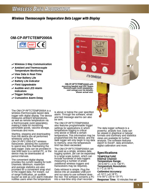
冰箱、冰柜温度无线监控系统软件使用手册(新)说明书
冰箱、冰柜温度无线监控系统软件使用手册唐山众智科技开发有限公司地址:河北省唐山市高新技术开发区大庆道86号电话:************************传真:************网址:邮编:063020E-mail:*************冰箱、冰柜温度无线监控系统软件使用手册一.安装1.1安装环境A:硬件环境:●计算机采用工业控制计算机或服务器;●必须安装声卡、音箱;●最低需求采用P4以上级别CPU、512M内存、40G以上硬盘,推荐 CUP主频1.8GHz以上、1G以上内存;●显示器分辨率为1024×768的显示模式。
B:软件环境:●操作系统:Window2000\XP\2003;●系统软件:IIS信息服务管理系统 5.0及以上版本(网络版需求),.netFramework2.0,SQL SRVER2000、SQL SERVER2005数据库,默认使用SQL SERVER 2005 EXPRESS;1.2安装步骤1.2.1安装.NET、SQL Server及冷链无线温度监控系统软件本安装程序会自动将.net软件以及SQL Server数据库自动安装到系统中。
运行安装盘中“setup.exe”文件根据提示安装应用软件。
点击图标,安装程序弹出如下窗口:图1.2.1-1 .net安装窗口点击按钮,弹出SQL Server安装窗口,如下图:图1.2.1-2 SQL Server安装窗口点击按钮,系统开始安装,NET及SQL Server软件,这个过程需要一段时间,请耐心等候。
.NET及SQL Server软件安装完成后,安装程序会继续安装冷链无线温度监控系统,如下图:图1.2.1-3 冷链无线温度监控系统点击按钮,选择安装程序的路径,如图图1.2.1-4 选择路径窗口点击按钮,弹出确认安装窗口,继续点击按钮,安装程序安装完成,如图1.2.1-6所示:图1.2.1-5 确认安装窗口图1.2.1-6 安装完成窗口安装软件后需要确保数据库操作用户具有安装目录的写入权限,否则运行程序时,可能不能正确附加数据库。
温度数据记录器系列用户指南说明书
OM-CP-HITEMP140X2High Temperature Dual ProbeData Logger SeriesUser’s Guide2Product OverviewThe OM-CP-HITEMP140X2 series of dual probe high temperature data loggers are comprised of a stainless steel data logger body and feature either two remote temperature probes one ambient and one remote temperature probe combination. This data logger series offers extreme flexibility for high temperature monitoring applications.The dual probes of the OM-CP-HITEMP140X2 series allow for simultaneous temperature monitoring and are ideal for applications such as oven mapping, surface temperature monitoring, autoclave validation, food processing, sterilization processes and much more.The OM-CP-HITEMP140X2-TD data logger models feature a 2” rigid, fast response, transitional diameter probe to measure ambient temperature, combined with a second stainless steel bendable or flexible RTD probe option.The OM-CP-HITEMP140X2-FP data logger models feature a 72”, lightweight flexible RTD probe, combined with a second stainless steel bendable probe or a second flexible RTD probe.The OM-CP-HITEMP140X2 data logger series is compatible with the latest version of the OM-CP Software. This allows for simple starting, stopping and downloading of collected data. Once the readings have been downloaded to the software, it can be viewed in graphic, tabular, and summary form for easy analysis, aswell as the potential to be exported into Excel for further calculations.Rigid Transitional Diameter Probe (TD)Stainless Steel Bendable RTD Probe (PT)Flexible RTD Probe (FP)OM-CP-HITEMP140X2 Series3Additional FeaturesSubmergibilityThe OM-CP-HITEMP140X2 series is rated IP68 and is fully submersible. They can be placed in environments up to 230’ (70m) of water.Bend Radius- The bendable probe can be bent to a 1/4 inch bend radius. The probe should not be bent within 1 inch of either weld joint.- The flexible probe should not be bent within 1 inch where the probe meets the logger or less than 1 inch from the probe tip.O-RingsO-ring maintenance is a key factor when properly caring for the OM-CP-HITEMP140X2 data loggers. The O-rings ensure a tight seal and prevent liquid from entering the inside of the device.Trigger SettingsThe device can be programmed to only record based off user configured trigger settings.1. In the Connected devices panel, select the intended device to change the settings.2. On the Device tab, in the Information group, click Properties . Users can also right-click on the device andselect Properties in the context menu.3. Click Trigger and configure the Trigger settings . Trigger formats are available in Window and Two Point(bi-level) mode. Window mode allows for one range of temperature monitoring and two point mode allows for two ranges.Note: This product is rated for use up to 140°C. Please heed the battery warning. The product will explode if exposed to temperatures above 140°C.Temperature ChannelsAll OM -CP-HITEM P140X2 data loggers feature 2 temperature channels. Thechannel number for each probe is identified on the top of the logger as shownbelow. The OM -CP Software will list the temperature channels in sequence,listing channel 1 first and channel 2 second, under the data logger device ID asshown to the right.Quick Start ManualOM-CP-HITEMP140X2 SeriesTroubleshooting TipsWhy is the wireless data logger not appearing in the software?If the OM-CP-HITEMP140X2 doesn’t appear in the Connected Devices panel, or an error message is received while using the OM-CP-HITEMP140X2, try the following:• Check that the OM-CP-IFC400 is properly connected. For more information, see Troubleshooting Interface Cable problems (below).• Ensure that the battery is not discharged. For best voltage accuracy, use a voltage meter connected to the battery of the device. If possible, try switching the battery with a new OM-CP-BAT110.• Ensure that no other Omega software is running in the background.• Ensure that Omega Software is being used.• Ensure that the Connected Devices panel is large enough to display devices. This can be verified by positioning the cursor on the edge of the Connected Devices panel until the resize cursor appears, then dragging the edge of the panel to resize it. The screen layout may also be reset in the options menu by selecting File, Options, and scrolling to the bottom.Troubleshooting Interface Cable problemsCheck that the software properly recognizes the connected OM-CP-IFC400 wireless transceiver.If the wireless data logger is not appearing in the Connected Devices list, it may be that the OM-CP-IFC400 is not properly connected.1. In the software, click the File button, then click Options.2. In the Options window, click Communications.3. The Detected Interfaces box will list all of the available communication interfaces. If the OM-CP-IFC400 is listed here, then the software has correctly recognized and is ready to use it.Check that Windows recognizes the connected OM-CP-IFC400 wireless transceiver.If the software does not recognize the OM-CP-IFC400, there may be a problem with Windows or the USB drivers.1. In Windows, click Start, right-click Computer and choose Properties or press Windows+Break as akeyboard shortcut.2. Click Device Manager in the left hand column.3. Double click Universal Serial Bus Controllers.4. Look for an entry for Data logger Interface.5.If the entry is present, and there are no warning messages or icons, then windows has correctlyrecognized the connected OM-CP-IFC400.6.If the entry is not present, or has an exclamation point icon next to it, the USB drivers may need to beinstalled. These are available on the software flash drive included with the OM-CP-IFC400.Ensure that the USB end of the OM-CP-IFC400 is securely connected to the computer.1. Locate the USB-A plug of the OM-CP-IFC400.2. If the interface cable is connected to the PC, unplug it. Wait ten seconds.3.Reconnect the cable to the PC.4.Check to make sure that the red LED is lit, indicating a successful connection.4Quick Start ManualInstallation GuideInstalling the Interface cable- OM-CP-IFC400 or OM-CP-IFC406Refer to the “Quick Start Guide” included in the package.Installing the softwareInsert the Omega Software Flash Drive in an open USB port. If the autorun does not appear, locate the drive on the computer and double click on Autorun.exe. Follow the instructions provided in the Installation Wizard. Device OperationConnecting and Starting the data logger1. Once the software is installed and running, plug the interface cable into the docking station.2. Connect the USB end of the interface cable into an open USB port on the computer. Place the data loggerinto the docking station.3. The data logger will automatically appear under Connected Devices within the software.4. For most applications, select “Custom Start” from the menu bar and choose the desired start method,reading rate and other parameters appropriate for the data logging application and click “Start”. (“Quick Start” applies the most recent custom start options, “Batch Start” is used for managing multiple loggers at once, “Real Time Start” stores the dataset as it records while connected to the logger.)5. The status of the device will change to “Running”, “Waiting to Start” or “Waiting to Manual Start”,depending upon your start method.6. Disconnect the data logger from the docking station and place it in the environment to measure.Note: The device will stop recording data when the end of memory is reached or the device is stopped. At this point the device cannot be restarted until it has been re-armed by the computer.Downloading data from a data logger1. Connect the logger to the docking station.2. Highlight the data logger in the Connected Devices list. Click “Stop” on the menu bar.3. Once the data logger is stopped, with the logger highlighted, click “Download”. You will be prompted toname your report.4. Downloading will offload and save all the recorded data to the PC.Product MaintenanceBattery ReplacementMaterials: OM-CP-BAT1101. Unscrew the bottom of the logger and remove the battery.2. Place the new battery into the logger. Note the polarity of the battery.3. Screw the cover back onto the logger.RecalibrationThe OM-CP-HITEMP140X2 standard calibrations points are 30°C and 140°C.Recalibration is recommended annually for any Omega data logger; a reminder is automatically displayedin the software when the device is due. Call for custom calibration options to accommodate specific application needs.56OM-CP-HITEMP140X2 General SpecificationsBattery WarningWARNING: FIRE, EXPLOSION, AND SEVERE BURN HAZARD. DO NOT SHORT CIRCUIT , CHARGE, FORCE OVER DISCHARGE, CRUSH, PENETRATE OR INCINERATE. BATTERY MAY LEAK OR EXPLODE IF HEATED ABOVE 150°C (302°F).Specifications subject to change.See Omega’s terms and conditions at OM-CP-HITEMP140X2 Series7OM-CP-HITEMP140X2-FP High Temperature Dual Probe Data Loggers with two Remote Temperature ProbesThe OM-CP-HITEMP140X2-FP series of dual probe high temperature data loggers are comprised of a stainless steel data logger body and feature two 72” flexible FP probes or are available with one flexible probe and a stainless steel bendable PT probe combination.The dual probes of this OM-CP-HITEMP140X2 series allow for simultaneous temperature monitoring andprovide flexibility in applications such as oven mapping, surface temperature monitoring, autoclave validation and sterilization processes.The OM-CP-HITEMP140X2-FP model offers two 72” long, lightweight, flexible RTD probes coated with PFA insulation. The FP probe design allows the probe to be easily maneuvered and is ideal for temperature monitoring inside test tubes, small vials, and other delicate applications. The narrow thermistor probe tip is compatible for use with the OM-CP-MICRODISC probe attachment allowing for precise surface temperature monitoring of shelving and more.The OM-CP-HITEMP140X2-FP-PT-1 and OM-CP-HITEMP140X2-FP-PT-5 models feature a 24” stainless steel bendable probe with the option of either a 1” or 5” probe tip (sheath). The stainless steel probe can be bent, angled, and coiled in any direction and formed into position as needed. The sharp probe tip allows for easyinsertion and has an extended measurement range of -200°C to +350°C.*Also Available with a 1 Inch Probe Tip*Quick Start ManualOM-CP-HITEMP140X2 SeriesOM-CP-HITEMP140X2-FP Specifications89OM-CP-HITEMP140X2-TD High Temperature Dual Probe Data Loggers with Ambient & Remote Temperature ProbesThe OM-CP-HITEMP140X2-TD data logger models feature a 2” rigid transitional diameter probe to measure ambient temperature, combined with a second bendable or flexible probe option. The rigid 2” TD probe is made of stainless steel, offers an ultra-fast response time and is suitable for measuring ambient temperatures in the harshest environments.The OM-CP-HITEMP140X2-TD-PT-1 and the OM-CP-HITEMP140X2-TD-PT-5 models include a 24” bendable probe made of stainless steel with either a 1” or 5” probe sheath at the tip. The stainless steel PT probe options provide the ability to retain shape when bent into position and the sharp probe tip allows for easy insertion. The stainless steel PT probes also offer an extended measurement range to accommodate extremely high temperatures.The OM-CP-HITEMP140X2-TD-FP combines the 2” rigid probe with the 72” RTD lightweight flexible RTD probe. The flexible FP probe option is a lightweight, pliable probe coated with PFA insulation making it ideal for use inside small vials and test tubes. This probe style has a narrow diameter, high accuracy and is ideal for steam sterilization and lyophilization. The FP probe is also compatible with the OM-CP-MICRODISC probeattachment, used for the surface temperature monitoring of shelving and more.Quick Start ManualOM-CP-HITEMP140X2 SeriesOM-CP-HITEMP140X2-FP Specifications10WARRANTY/DISCLAIMEROMEGA ENGINEERING, INC. warrants this unit to be free of defects in materials and workmanship for a period of 61 months from date of purchase. OMEGA’s WARRANTY adds an additional one (1) month grace period to the normal five (5) year product warranty to cover handling and shipping time. This ensures that OMEGA’s customers receive maximum coverage on each product.If the unit malfunctions, it must be returned to the factory for evaluation. OMEGA’s Customer Service Department will issue an Authorized Return (AR) number immediately upon phone or written request. Upon examination by OMEGA, if the unit is found to be defective, it will be repaired or replaced at no charge. OMEGA’s WARRANTY does not apply to defects resulting from any action of the purchaser, including but not limited to mishandling, improper interfacing, operation outside of design limits, improper repair, or unauthorized modification. This WARRANTY is VOID if the unit shows evidence of having been tampered with or shows evidence of having been damaged as a result of excessive corrosion; or current, heat, moisture or vibration; improper specifica-tion; misapplication; misuse or other operating conditions outside of OMEGA’s control. Components in which wear is not war-ranted, include but are not limited to contact points, fuses, and triacs.OMEGA is pleased to offer suggestions on the use of its various products. However, OMEGA neither assumes respon-sibility for any omissions or errors nor assumes liability for any damages that result from the use of its products in accordance with information provided by OMEGA, either verbal or written. OMEGA warrants only that the parts manufactured by the company will be as specified and free of defects. OMEGA MAKES NO OTHER WARRANTIES OR REPRESENTATIONS OF ANY KIND WHATSOEV ER, EXPRESSED OR IMPLIED, EXCEPT THAT OF TITLE, AND ALL IMPLIED WARRANTIES INCLUDING ANY WARRANTY OF MERCHANTABILITY AND FITNESS FOR A PARTICULAR PURPOSE ARE HEREBY DISCLAIMED. LIMITATION OF LIABILITY: The remedies of purchaser set forth herein are exclusive, and the total liability of OMEGA with respect to this order, whether based on contract, warranty, negli-gence, indemnification, strict liability or otherwise, shall not exceed the purchase price of the component upon which liability is based. In no event shall OMEGA be liable for consequential, incidental or special damages.CONDITIONS: Equipment sold by OMEGA is not intended to be used, nor shall it be used: (1) as a “Basic Component” under 10 CFR 21 (NRC), used in or with any nuclear installation or activity; or (2) in medical applications or used on humans. Should any Product(s) be used in or with any nuclear installation or activity, medical application, used on humans, or misused in any way, OMEGA assumes no responsibility as set forth in our basic WARRANTY / DISCLAIMER language, and, additionally, purchaser will indemnify OMEGA and hold OMEGA harmless from any liability or damage whatsoever arising out of the use of the Product(s) insuch a manner.FOR WARRANTY RETURNS, please have the following infor-mation available BEFORE contacting OMEGA:1. P urchase Order number under which the product was PURCHASED,2. M odel and serial number of the product under warranty, and3. R epair instructions and/or specific problems relative to the product.FOR NON-WARRANTY REPAIRS, consult OMEGA for current repair charges. Have the following information available BEFORE contacting OMEGA:1. Purchase Order number to cover the COST of the repair,2. Model and serial number of the product, and 3. R epair instructions and/or specific problems relative to the product.OMEGA’s policy is to make running changes, not model changes, whenever an improvement is possible. T his affords our customers the latest in technology and engineering. OMEGA is a registered trademark of OMEGA ENGINEERING, INC.© Copyright 2014 OMEGA ENGINEERING, INC. All rights reserved. This document may not be copied, photocopied, reproduced, translated, or reduced to any electronic medium or machine-readable form, in whole or in part, without the prior written consent of OMEGA ENGINEERING, INC.RETURN REQUESTS / INQUIRIESDirect all warranty and repair requests/inquiries to the OMEGA Customer Service Department. BEFORE RET URNING ANY PRODUCT (S) T O OMEGA, PURCHASER MUST OBT AIN AN AUT HORIZED RET URN (AR) NUMBER FROM OMEGA’S CUST OMER SERVICE DEPARTMENT (IN ORDER TO AVOID PROCESSING DELAYS). The assigned AR number should then be marked on the outside of the return package and on any correspondence.The purchaser is responsible for shipping charges, freight, insurance and proper packaging to prevent breakage in transit.Servicing North America:U.S.A.: Omega Engineering, Inc., One Omega Drive, P.O. Box 4047 S tamford, CT 06907-0047 USA Toll-Free: 1-800-826-6342 (USA & Canada only) Customer Service: 1-800-622-2378 (USA & Canada only) Engineering Service: 1-800-872-9436 (USA & Canada only) Tel: (203) 359-1660 Fax: (203) 359-7700 e-mail:**************For Other Locations Visit /worldwide ***********************The information contained in this document is believed to be correct, but OMEGA accepts no liability for any errors it contains, and reserves the right to alter specifications without notice.WARNING: These products are not designed for use in, and should not be used for, human applications.MQS5091/1014。
温度监控系统使用说明书
精英血液资源平台温度管理系统贵州精英企业科技发展有限公司http://www。
gzjyqy。
com一、概述。
随着“信息时代”的到来,作为获取信息的手段——传感器技术得到了显著的进步,其应用领域越来越广泛,对其要求越来越高,需求越来越迫切。
传感器技术已成为衡量一个国家科学技术发展水平的重要标志之一。
传感器的被测信号来自于各个应用领域,每个领域都为了改革生产力、提高工效和时效,各自都在开发研制适合应用的传感器,于是种类繁多的新型传感器及传感器系统不断涌现。
温度传感器是其中重要的一类传感器。
其发展速度之快,以及其应用之广,并且还有很大潜力。
面对如此巨大的发展空间,精英公司针对于各地方血站,医院等相关医疗部门设计开发了温度监控系统,一套系统可达到32路温度检测对象(如冰箱)的同时监控,很好的解决了由人工抄写温度数据带来的繁琐以及不准确的问题。
1、系统总体功能●32路温度检测对象的同时监控。
●24小时实时温度采集。
●温度超标预警。
●温度统计查询,报表。
●温度数据的共享。
(卫生厅等上级部门能实时监控各单位的温度情况)●温度超标短信通知。
2、运行环境(1) 软件环境Windows 操作系统:●Windows 9X/ME。
●Windows 2000/XP(推荐)。
(2) 硬件环境建议配置:CPU:奔腾III 800 以上内存:128 MB以上显卡:标准 VGA,24 位真彩色其它:光驱、鼠标3、接线说明注意:上图中的红线和黑线分别接485转换器的D+/A,D-/B,具体接法在传感器的线上贴的有标签。
按照标签提示连接即可。
可以在该线和485接口间接延长线。
二、具体模块介绍1、参数配置:打开温度程序,在主菜单系统配置--- 参数配置如下图:说明:串口选择:代表485转换口接计算机的COM口编号,一般计算机为COM1或COM2口。
(以用户接入的口为准)。
温度保存间隔时间:代表系统每次采集温度的时间,即每次采集入库时间,方便后面的查询。
测温监控系统软件说明书
杭州宇诺电子科技有限公司——在线测温监控系统软件使用说明书2014年11月23日1软件概述:在线测温监控系统,是杭州宇诺电子科技有限公司针对在线测温产品开发的一套专业化系统软件。
该软件具有对测温点的温度数据的监测,采集,处理和分析功能,能够实现对测温点温度变化情况的实时监控和分析。
2系统配置:本软件可在Windows XP, Window7的各个版本(除家庭版外)的系统下运行。
3计算机的硬件配置处理器:奔腾I I以上C P U内存: 1GB以上硬盘空间:500GB显卡:集成显卡或独立显卡均可。
其他:标准配置4软件的功能1、实时数据显示各个测温节点的温度数据和报警情况,传感器接收状态。
2、历史数据查看开关柜在指定日期内的所有测温节点或指定节点的历史温度数据。
3、温度曲线查看开关柜在指定日期内的所以测温节点或指定节点的历史温度曲线。
4、报警记录显示温度报警,预报警,温升报警,通讯失败等报警信息。
5、日志信息记录用户的一些日常操作信息。
6、用户管理查看,添加,修改和删除当前用户的信息。
7、参数设置查看,添加,修改和删除系统中的设备以及测温节点的相关参数。
8、关于查看版本信息。
5软件操作说明1、双击桌面的软件图标,如图5-1所示。
图5-12、在登录界面(如图5-2所示)输入用户名和密码点击登录(首次操作我们将提供临时用户名和密码)图5-23、进入主界面,可查看实时数据(如图:5-3所示)图5-3在实时数据查看界面,可以通过对左边树形目录复选框的勾选筛选要查看的实时数据。
通过“区域”和“设备”页面的切换可以分别根据测温位置或设备名称查看实时数据的显示。
4、历史数据的查看,点击顶端工具栏中的“历史数据”,切换到历史数据界面,如图5-4所示。
图5-4在该界面下方有两个选项:“实时刷新历史数据”,“查看历史数据”在使用过程中,我们通常选择“查看历史数据”。
当需要查看某一日的历史数据时,我们只需在“选择以往历史数据日期”中选择相应的日期,然后在左边的树形目录中选择查看的开关柜,即可看到该开关柜中的当日的全部温度采样数据。
温度数据记录器产品说明书

1High TemperatureDual Channel Data LoggersOM-CP-HITEMP140X2-TD SeriesU O M-CP-HITEMP140X2-TD-FP-72 Has One RigidAmbient Probe and One Flexible Probe U O M-CP-HITEMP140X2-TD-PT -1 andOM-CP-HITEMP140X2-TD-PT -5 Have One Rigid Ambient Probe and One Stainless Steel Bendable Probe U R igid Ambient Probe Measures from -200 to 260°C (-328 to 500°F)U F lexible Probe Measures from -60 to 260°C (-76 to 500°F)U S tainless Steel Bendable Probe Measures from -200 to 350°C (-328 to 662°F)U O perating Temperature Range (Data Logger): -40 to 140ºC (-40 to 284ºF)U ±0.1°C (±0.18°F) Accuracy U S ubmersible (IP68)U T rigger S ettings U P rogrammable Start and Stop TimeThe OM-CP-HITEMP140X2-TD series of dual probe data loggers offer extreme flexibility for high temperature monitoring applications. These models all feature a 5.1 cm (2") rigid transitional diameter probe to measure ambient temperature, combined with a second bendable or flexible probe option. The rigid ambient probe is made of stainless steel, offers a fast response time and is suitable for the harshest environments. The OM-CP-HITEMP140X2-TD-PT -1 and theOM-CP-HITEMP140X2-TD-PT -5 models combine the 5.1 cm (2") rigid ambient probe with a 61 cm (24") bendable probe made of stainless steel with either a 2.5 cm (1") or 12.7 cm (5") probe sheath at the tip. The stainless steel PT probe options provide the ability to retain shape when bent into position and offer an extremely high measurement range of up to 350°C. The OM-CP-HITEMP140X2-TD-FP-72 combines the 5.1 cm (2") rigid ambient probe with a 183 cm (72") long lightweight RTD flexible probe, designed for easy placement. The flexible probe option is very pliable and coated with PFA insulation making it ideal for use inside small vials and test tubes. This probe style has a narrow diameter, high accuracy and is ideal for steam sterilization and lyophilization. The flexible probe is also compatible with the OM-CP-MICRODISC probe attachment, used for the surface temperature monitoring of shelving and more.The operating temperature range for the data logger body is -40 to 140°C (-40 to 284ºF). Because of the simultaneous ambient and remote temperature recording, the OM-CP-HITEMP140X2-TD series is ideal for use in autoclave mapping, food processing applications, and much more.The OM-CP-HITEMP140X2-TD series utilizes the latest software. This allows for simple starting, stopping and downloading of collected data. The devices are able to store up to 32,700 time and date stamped readings in non-volatile solid state memory. Once the readings have been downloaded to the software, it can beviewed in graphic, tabular, and summary form for easy analysis, as well as the potential to be exported into Excel for further calculations.The OM-CP-MULTIMOUNT -Z is a versatile mount or stand for use with the OM-CP-HITEMP140 series of data loggers. It can be used to stabilize a logger inside an autoclave, or screwed to a flat surface to create an anchored base. Made of 316 stainless steel, the OM-CP-MULTIMOUNT -Z is able to withstandtemperatures up to 150°C (302°F) making it ideal foruse in autoclave sterilization processes.OM-CP-HITEMP140X2-TD-FP-72shown actual size.2TEMPERATURETemperature Sensor:O M-CP-HITEMP140X2-TD-PT -1,OM-CP-HITEMP140X2-TD-PT -5: Rigid ambient RTD probe with a stainless steel bendable RTD probeO M-CP-HITEMP140X2-TD-FP-72: Rigid ambient RTD probe with a PFA insulated flexible RTD probe Probe Measurement Range:Rigid Ambient Probe: -200 to 260°C (-328 to 500°F) S tainless Steel Bendable Probe: -200 to 350°C (-328 to 662°F)Flexible Probe: -60 to 260°C (-76 to 500°F)Temperature Resolution: 0.01°C (0.02°F)Calibrated Accuracy: ±0.1°C (±0.18°F)GENERALReading Rate: 1 reading every second up to 1 reading every 24 hours Memory: 32,767 readingsStart Modes:• Software programmable immediate start • Delay start up to 18 months in advanceStop Modes: Manual or Timed (specific date and time)Real Time Recording: May be used with PC to monitor andrecord data in real time Password Protection: An optional password may beprogrammed into the device to restrict access to configuration options. Data may be read out without the password Readings in Trigger Settings Mode: 16,383 readingsTrigger Settings: High and Low limits may be set. Once datameets or exceed set limits, the device will record to memory.Bi-level start and stop triggers can also be programmed. Userscan specify the number of readings to take after the devicetriggers. (T riggering on channel 1 only)Memory Wrap Around: Y es (software selectable)Battery Type: 3.6V high-temperature lithium battery included;user replaceable Battery Life: 1 year typical [1 minute reading rate at 25°C (77°F)]Calibration: Digital calibration through software Calibration Date: Automatically recorded within deviceData Format: Date and time stamped °C, °F , °R, KTime Accuracy: 1 minute/month at 25°C (77°F)Computer Interface: OM-CP-IFC400 USB docking station or OM-CP-IFC406 multiplexer interface required; 125,000 baud Software: Windows XP SP3/Vista/7 and 8 (32-bit and 64-bit)Operating Environment: -40 to 140°C (-40 to 284°F),0 to 100% RH, 0.002 to 100 psia IP Rating: IP68Dimensions (Body): 48 H x 24.6 mm dia (1.89 x 0.97")Dimensions (Probe): R igid Ambient Probe (All Models): 51 L x 3.2 mm dia(4.8 mm transitional dia); 2.0 x 0.125" (0.188" transitional dia)OM-CP-HITEMP140X2-TD-PT -1 Stainless Steel Bendable Probe: Probe Tip: 42 L x 3.2 mm dia (1.7 x 0.125")Bendable Portion: 559 L x 1.6 mm dia (22 x 0.062")O M-CP-HITEMP140X2-TD-PT -5 Stainless Steel Bendable Probe:P robe Tip: 121 L x 3.2 mm dia (4.8 x 0.125") with 25 L x 4.8 mm dia (1 x 0.188") handleBendable Portion: 559 L x 1.6 mm dia (22 x 0.062")OM-CP-HITEMP140X2-TD-FP-72 Flexible Probe: 1829 L x 2.5 mm dia (72 x 0.1")Weight:OM-CP-HITEMP140X2-TD-PT: 85 g (3.0 oz) OM-CP-HITEMP140X2-TD-FP: 100 g (3.5 oz)Materials: Body: 316 stainless steel, PEEK Bendable Probe: 316 stainless steelFlexible Probe:PFA insulated cable OM-CP-HITEMP140X2-TD-PT -1shown smaller than actual size.OM-CP-HITEMP140X2-TD-PT -5shown smaller than actual size.OM-CP-IFC400, Windows ® software displays datain graphical or tabular format.3Comes complete with 3.6V lithium battery. Operator’s manual and USB interface cable are included with the OM-CP-IFC400 software/cable package and OM-CP-IFC406 multiplexer. OM-CP-IFC400 required for data logger operation. Both models sold separately.Ordering Example: OM-CP-HITEMP140X2-TD-FP-72-CERT high temperature data logger with one 5.1 cm (2") rigid ambient probe and one 183 cm (72") flexible probe and NIST calibration certificate.OM-CP-IFC406 multiplexer data logger interface, shown smaller than actual size (data loggers sold separately).OM-CP-MICRODISC surface temperature probe attachment (shown with probeOM-CP-MULTIMOUNT-Z bracket, sold separately.。
DeltaTRAK 温度记录仪管理软件使用说明书

数据记录仪的特点
·数据记录仪能多次重复使用。
·电池能自行更换。
·断电数据保护功能,当电池没电时数据能保持不丢失。
·标准25针通讯端口进行通讯,既一般的打印机口就可以和数据记录仪进行通讯。
·数据记录仪具有防潮功能。
·绿色和红色的指示等用来表明记录仪的运行和报警等信息。
如何开启数据记录仪
1)首先需要将数据记录仪软件成功安装在您的电脑中。
2)根据第4页的介绍将数据记录仪和电脑相连,根据第5页的介绍将数据管理软件安装到您的电脑。
3)数据记录仪的出厂设置是手动开启模式。
4)数据记录仪开始工作前必须根据第16页的说明进行采样间、报警等参数的设置。
5)参数设置成功后,数据记录仪便可脱离电脑进行工作,如是手动开启模式,按一下手动开关,记录仪便开启工作;如不是手动开启模式,记录仪参数设置完成后便直接开启工作。
·先进先出模式(Loop Mode):当记录仪的数据存储满时,后面的数据存储进来时前面的数据就会被挤出。
·使用记录仪时,务必先打开数据管理软件后再将记录仪和电脑相连。
·下载数据后,您可以选择停止记录仪或记录仪继续工作直到记录存储满后停止。
例如:
·记录仪预先设置记录5天。
·1天后,您就下载数据。
·您可以选择下载后停止记录仪或记录仪继续工作直到记录达到预先设置的5天时间。
数据记录仪管理软件
使用手册
美国:DeltaTRAK
中国国际分销商:杭州迈科派科技有限公司
E-mail:micropine@
重点提醒
使用记录仪前必须先用此软件对记录仪进行设置,所有记录仪都有一个专用序列号,如:00100000
- 1、下载文档前请自行甄别文档内容的完整性,平台不提供额外的编辑、内容补充、找答案等附加服务。
- 2、"仅部分预览"的文档,不可在线预览部分如存在完整性等问题,可反馈申请退款(可完整预览的文档不适用该条件!)。
- 3、如文档侵犯您的权益,请联系客服反馈,我们会尽快为您处理(人工客服工作时间:9:00-18:30)。
查询温度历史数据:在姓名输入框中输入“李”字
,点击【查
询】按钮,表格中则显示所有姓名中包含“李”字的数据,同样方法,你可以根据地址、 电话、温度范围、时间范围来查询,也可以根据以上几个组合查询。
4.9 用户温度汇总统计
进入主界面后,点击
后,显示【用户温度汇总统计】界面,如下图所示:
温度监控系统
这里可以设置表格中显示的背景 色。右键它可以恢复默认设置。
后,显示【用户温度详细信息】界面,如下图所示:
温度监控系统
第 8 页 共 13页
打印日期:4/26/2021
温度监控系统使用说明书
这里是查询条件,输入内容后点 【查询】按钮即可查询数据了。
图 在该界面中,可以查询用户温度上报的所有历史数据,你可以根据用户名、地址、电话、温 度范围、时间范围来查询上报的历史数据。
2 设备参数.......................................................................................................................................2 3 系统网络结构...............................................................................................................................2 4 温度监控系统软件.......................................................................................................................3
4.2 系统登录
双击桌面上的【温度监控系统】快捷方式图标后,出现如下图所示的登录界面:
图2 输入正确的用户名及密码后,点击【登录】按钮。 若输入的用户名及密码正确即可进入系统。 若输入的用户名或密码不正确,则提示“你输入的用户名或密码不正确!”。 若服务器无法连接,或你的电脑不能正常上网,则提示“服务器正在维护!”。
注:如果状态是“线路或设备故障”则该条数据有背景色。
查询用户资料:在姓名输入框中输入“李”字
,点击【查询】
按钮,表格中则显示所有姓名中包含“李”字的数据,同样方法,你可以根据地址或电 话查询,也可以根据以上几个组合查询。如果你只想显示“线路或设备故障”的机器时,
你可以将“只显示报警”复选框打上钩
。
添加监控用户资料:点击【添加】按钮 图所示:
打印日期:4/26/2021
温度监控系统使用说明书
用户温度上报时,会显示 在这个表示中。
图 该界面监控用户最新温度上报情况,当有温度上报时,动态信息(下图所示)里显示上报用 户的名称、地址、温度、时间,同时表格(上图所示)中自动增加一条数据。
4.8 用户温度详细信息
进入主界面后,点击
用户温度上报时,这里会 显示,并且会变色。 图
,弹出添加监控用户资料的界面,如下
温度监控系统
第 6 页 共 13页
打印日期:4/26/2021
温度监控系统使用说明书
图 分别输入姓名、地址、绑定电话后,点击【确定】按钮,则添加成功。
注:绑定电话一定要输入正确,并且不能与其它用户重复!
修改监控用户资料:点击【修改】按钮 用户资料的界面,如下图所:
1.1 阅读对象
本手册的主要用途是帮助您熟悉使用温度监控系统软件产品。本手册的阅读 对象包括:供暖公司、省市区级质量技术监督局用户。
2 设备参数
3 系统网络结构
系统通过数据通讯服务器将 PSTN 与 INTERNET 连接,数据通讯服务器收到温度数据 后,通过 UDP 消息通知监控电脑,监控电脑能实时显示用户最新上报的温度,系统网络结 构如下图所示:
图
曲线显示:将“最高温度曲线”复选框打上钩
,图表中显示最高温
度曲线,否则不显示。同理,你可以控制最低级平均温度曲线的显示情况。
4.11 用户申告信息管理
进入主界面后,点击 如下图所示:
后,显示【用户申告信息管理】的界面,
温度监控系统
第 11 页 共 13页
打印日期:4/26/2021
4.10 用户温度曲线图
进入主界面后,点击
后,显示【用户温度曲线】的界面,如下图所示:
温度监控系统
第 10 页 共 13页
打印日期:4/26/2021
温度监控系统使用说明书
图 该界面可以直接的显示用户温度变化曲线,三条曲线分别代表最高温度、最低温度、平 均温度,非常直观。 自动筛选用户:在选择用户下拉框中输入“1”,下拉框中自动列出用户姓名或绑定电 话包含“1”的用户。
或双击表格中的数据,弹出修改监控
图 输入要修改的内容,点击【确定】按钮,完成修改。
删除监控用户资料:选择要删除的数据,点击【删除】按钮 示的提示,点击【确定】按钮后,删除用户资料。
,弹出如下图所
图
4.7 温度数据实时监控
进入主界面后,点击
后,显示【温度数据实时监控】界面,如下图所示:
温度监控系统
第 7 页 共 13页
4.1 系统安装...........................................................................................................................3 4.2 系统登录...........................................................................................................................3 4.3 系统主界面.......................................................................................................................3 4.4 修改密码...........................................................................................................................4 4.5 操作员信息管理...............................................................................................................4 4.6 监控用户信息管理...........................................................................................................6 4.7 温度数据实时监控...........................................................................................................7 4.8 用户温度详细信息............................................................................................................8 4.9 用户温度汇总统计............................................................................................................9 4.10 用户温度曲线图.............................................................................................................10
4.3 系统主界面
登录成功后,自动进入系统,显示如下图所示的主界面:
温度监控系统
第 3 页 共 13页
打印日期:4/26/2021
温度监控系统使用说明书 工具栏图标
快捷菜单
关闭当前窗口
温度上报 提醒信息
4.4 修改密码
进入主界面后,点击
图3 ,弹出所下图所示界面:
图4 输入原密码后,再输入两次输入密码,点击【确定】按钮,若不出现下列情况,则提示 “密码修改成功”后,完成密码修改。 若原密码错误,提示“原密码不正确!”信息。 若两次新密码不一致,提示“两次输入的密码不一致!”信息。
注:除系统管理员外,用户只能查看隶属于本部门的监控用户资料。 添加操作员资料:点击【添加】按钮,出现添加操作员资料窗口,如下图所示:
图 输入完整资料后,点击【确定】按钮,完成添加,修改操作员资料方法类似。
删除操作员资料:选择要删除的数据,点击【删除】按钮 的提示,点击【确定】按钮后,删除用户资料。
,弹出如下图所示
图
第 9 页 共 13页
打印日期:4/26/2021
温度监控系统使用说明书
用户上报的温度经过服务器计算,汇总显示在该表格中,通过该界面可以清楚的显示用 户某天的最高、最低、平均温度,也可以显示某天中从 0 点至 23 点的最高、最低、平均温 度。
查询温度统计数据:查询方法与前面表述的一样,如果想显示 0 点至 23 点的统计数据
温度监控系统
第 1 页 共 13页
打印日期:4/26/2021
温度监控系统使用说明书
1 用户手册简介
感谢您使用本公司的温度监控系统软件产品! 温度监控关系到千千万万老百姓的生活,让供暖公司全局(省略)
