S6020L中文资料
400千瓦康明斯发电机组参数
DCEC QSZ13系列柴油发电机组 技术参数扬州福康斯发电机有限公司技术部公司网址:销售热线:138 522 17951 传真电话:2 公司地址:江苏省扬州市江都区宜陵工业园公司简况公司文化◇企业价值理念—体现自我价值,共创美好未来 ◇员工精神—忠诚、协作、专业、进取 ◇经营理念—诚信、合作、共赢、发展 ◇服务理念—服务创造美好印象公司历史◇2000年7月扬州福发发电机有限公司成立◇2001年公司获得上柴、重庆康明斯、东风康明斯、三柴、MTU等柴油机厂家 OEM 证书;广州英格、无锡法拉第、上海马拉松等电机厂家 OEM 证书◇2002年年销售额突破5000万◇2003年公司获得无锡斯坦福(全球最大发电机厂家)OEM 证书 ◇2005年扬州福康斯发电机有限公司成立◇2000-2008年我公司锐意创新,连续8年销售额和上缴利税额平均 分别以35%和15%的速度增长◇2008-2013年福康斯系列发电机组采用中美合资康明斯 ( CUMMINS)、瑞典原装进口沃尔沃(VOLVO)、三菱(MITSUBISH)、奔驰( MTU)、 珀金斯(PERKINS)、道依茨(DEUTZ)、韩国原装进口斗山 (DOOSAN)、里卡多 (RICARDO)、潍坊(WEIFANG)、上柴(SHANGCAI)、等国内外知名品牌发动机 作原动力,并选配世界一流技术的斯坦福(STAMFORD)、马拉松( MARATHON)、 利来森玛(LEROY-SOMER)及国产知名发电机,以保证产品质量优异。
领先的技术,灵活的设计,生产出具有自主知识产权的”FKS ”品牌发电机组。
扬州福康斯DCEC QSZ13系列机组技术资料机组型号 运行模式 功率 转速 FKS-C450EkW/KVA rpm 常用功率400/5001500备用功率450/562.5-. 柴油机性能符合GB/T2820-. 标定功率根据GB/T1147.1→常用功率:用于可变载荷应用,全年无使用小时限制。
S60手持式数据采集器

S60手持式数据采集器用户手册2011年08月前言关于本手册感谢您选择本公司的产品。
本手册可帮助您简单的学会使用本产品。
使用前请通读本手册,并保管好,以便所有使用本产品的人均可阅读。
版权声明本手册内所收录信息及内容为说明产品目前状况,不具保证意涵,包括且不限于任何暗示性或可销售性保证,或适用于某一特殊目的保证;产品以实物为准,本手册内容有可能与实物有所差异,恕不另行通知。
本手册内包含有受版权法保护的独家专利信息,版权所有。
除版权法允许部分,否则未经中山市讯华软件有限公司科技有限公司书面同意,不得影印、重制作、修改或翻译部份或全部内容。
控制本产品的程序部分亦受版权法保护,版权所有,不得侵犯。
Microsoft、ActiveSync、Pocket IE、Pocket Word、Windows、Windows 98、Windows Me、Windows NT、Windows 2000、Windows XP、Windows标志、Windows CE标志或为注册商标,或为Microsoft Corporation在美国及/或其它国家之注册商标。
Microsoft产品为Microsoft Licensing, Inc.授权之OEM产品,Microsoft Licensing, Inc.为Microsoft完全拥有。
本手册内所提及的所有其它品牌名称及产品名称皆为各公司的商标名、服务标志或注册商标。
目录第一章原装配件2第二章产品简介3主要功能特点3产品详细参数4正面(功能介绍)5键盘(功能介绍)错误!未定义书签。
背面(功能介绍)错误!未定义书签。
第三章开始使用8点触操作9更改日期时间10输入文字11扫描条形码14与电脑联机15查看电池电量15校正触摸屏16第四章售后服务181. 支持服务182. 保修期限193. 保修范围19第一章原装配件原装配件您购买的设备包含以下配件主机: 1台电池:2块充电器: 1个数据线: 1条使用手册: 1套合格证: 1套2 / 20质保书: 1本手写笔: 1支防滑背带: 1套注意事项本设备某些功能取决于设备具体配置,请购买时对照配置型号,使用本产品。
PSS60资料
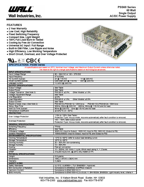
AC/DC Power SupplyFEATURES● 2 Year Warranty● Low Cost, High Reliability● Fixed Switching Frequency● Compact Size, Light Weight● 100% Full Load Burn-In Tested● Cooling by Free Air Convection● Universal AC Input / Full Range● Built-In EMI Filter, Low Ripple and Noise● High Efficiency, Low Working Temperature● Short Circuit, Overload, and Over Voltage ProtectedSPECIFICATIONS: PSS60 SeriesAll specifications are based on 25o C, Nominal Input Voltage, and Maximum Output Current unless otherwise noted.We reserve the right to change specifications based on technological advances.INPUT SPECIFICATIONSInput Voltage Range 85 ~ 264VAC or 120 ~ 370VDCInput Frequency 47 to 63HzAC Current (typical) 2A @ 115VAC 1A @ 230VACInrush Current (typical) Cold Start 20A @ 115VAC 40A @ 230VACLeakage Current < 3.5mA @ 240VACOUTPUT SPECIFICATIONSOutput Voltage See TableOutput Power See TableVoltage Tolerance (See Note 3) PSS-60-5: ±2.0%; Other Models: ±1.0%Voltage Adjustment Range See TableLine Regulation ±0.5%Load Regulation PSS-60-5: ±1.0%; Other Models: ±0.5%Output Current See TableRipple & Noise (max) (See Note 2) PSS-60-5 & PSS-60-12: 120mVp-p; PSS-60-15 & PSS-60-24: 150mVp-pSetup, Rise Time 300ms, 50ms @ 230VAC 800ms, 50ms @ 115VAC and full loadHold Up Time (typical) 80ms @ 230VAC 12ms @115VAC and full loadTemperature Coefficient ±0.03%/°C (0 ~ 50°C)PROTECTIONOver Voltage Protection 115% to 135% (See Table)Protection Type: Hiccup mode, recovers automatically after fault condition is removed.Overload Protection 105 ~ 150% rated output powerProtection Type: Hiccup mode, recovers automatically after fault condition is removed.GENERAL SPECIFICATIONSSwitching Frequency 77KHzEfficiency See TableWithstand Voltage 3000VAC (Input to Output), 1500VAC (Input to FG), 500VAC (Output to FG)Isolation Resistance 100MΩ/500DC (Input to Output, Input to FG, and Output to FG)ENVIRONMENTAL SPECIFICATIONSWorking Temperature -10°C to +60°C (refer to output load derating curve)Storage Temperature -20°C to +85°CWorking Humidity 20 ~ 90% RH non-condensingStorage Humidity 10 ~ 95% RHCooling Free air convectionVibration 10 ~ 500Hz, 2G 10min./1 cycle, 60min each along X, Y, Z axes.MTBF 316,200 hours min. @ 25°C (MIL-HDBK-217F)PHYSICAL SPECIFICATIONSWeight 510 gramsDimensions 159(L) x 97(W) x 38(H) mmWarranty 2 yearsSAFETY & EMCSafety Standards UL1012, UL60950-1, TUV EN60950-1 ApprovedEMI Conduction & Radiation Compliance to EN55022 (CISPR22) Class BHarmonic Current Compliance to EN61000-3-2,-3EMS Immunity Compliance to EN61000-4-2,3,4,5,6,8,11; ENV50204, EN55024, Light industry level, criteria AAC/DC Power SupplyOUTPUT VOLTAGE / CURRENT RATING CHARTModel Number Input VoltageOutput VoltageVoltage Adjust. Range Output CurrentOutput Power Efficiency Over Voltage Protection PSS-60-5 5 VDC 4.75 ~ 5.5V 12A 60W 73% 5.75 ~ 6.75V PSS-60-12 12 VDC 10.8 ~ 13.2V 5A 60W 76% 13.8 ~ 16.2V PSS-60-15 15 VDC 13.5 ~ 16.5V 4A 60W 77% 17.25 ~ 20.25V PSS-60-2485 ~ 264 VAC(120 ~ 370 VDC)24 VDC21.6 ~ 26.4V2.5A60W79%27.6 ~ 32.4VNOTES1. All parameters NOT specially mentioned are measured at 230VAC input, rated load, and 25°C ambient temperature.2. Ripple & noise are measured at 20MHz bandwidth by using a 12" twisted pair-wire terminated with a 0.1uF& 47uF parallel capacitor.3. Tolerances include set up tolerance, line regulation, and load regulation.4. Line Regulation is measured from low line to high line at rated load.5. Load regulation is measured from 0% to 100% rated load.6. The power supply is considered a component, which will be installed into final equipment. The final equipment must be re-confirmed that it still meets EMC directives.BLOCK DIAGRAMDERATING CURVESTATIC CHARACTERISTICS (24V)fosc: 77KHzAC/DC Power SupplyMECHANICAL DRAWINGUnit: mmTerminal Pin No. AssignmentPin No. Assignment1 AC/L2 AC/N3 FG(-V)OUTPUT4 DC(+V)5 DCOUTPUT。
全新沃尔沃S60产品特性手册20110311

带加热功能的外后视镜
特性:全新沃尔沃S60的外后视镜造型饱满、 浑厚,动感时尚,符合空气动力学设计,既能 获得最佳视野又能保持整车的流线造型降低风 噪,同时具备电加热功能,在恶劣天气时令后 方视野更清晰。 优势利益:造型饱满、浑厚,充满力量感。
地面照明灯
特性:全新沃尔沃S60外后视镜下方带有一个 地面照明功能,驾驶员上车时为其照亮附近的 路。 优势利益:地面照明功能给予驾驶者尊贵的感 受犹如五星级酒店的氛围灯。
11
倒“L”型尾灯设计
特性:全新沃尔沃S60采用了新造型的尾灯设计,尾灯从后叶子板 延伸到行李厢盖上,并且呈现倒“L”造型,扩张了尾部的视觉宽 度,并且使得尾灯更易辨认。 优势利益:增加尾部视觉宽度、提高辨识度。
12
激情跃动轿跑造型
新颖炫亮车身色彩: 全新沃尔沃S60车身颜色和车辆的造型一样充满动感与现代气息,彰显运动与时尚。
轿跑式溜背C柱
特性:全新沃尔沃S60吸收了双门Coupe轿跑车型 的设计灵感,在C柱部分采用了后延式溜背设计, 使车身后部形成一种紧凑的楔形轮廓,在减少空气 阻力的同时,令车身后部的线条更加流畅。 优势利益:溜背式C柱设计,使车辆更动感。
车窗环绕镀铬饰条
特性:全新沃尔沃S60采用了车窗环绕 镀铬饰条,侧窗玻璃周围被镀铬饰条围 绕,使车侧轮廓更清晰,更显尊贵和豪华。 优势利益:彰显出动感、时尚和豪华尊贵 的感受。
特性:全新沃尔沃S60前脸采用了大型进气 格栅和加大的LOGO设计。更加引人注目, 在凸显出全新沃尔沃S60年轻、动感、活力 的同时彰显出对沃尔沃品牌的自信与自豪。 优 势 利 益 : 超 大 的 LOGO 让 沃 尔 沃 更 显大 气,更富时尚感,很远的距离就能够让人一 眼认出沃尔沃。
伊顿(Eaton)5PX系列UPS安装和用户手册说明书

5PX 1500i RT2U5PX 2000i RT2U5PX 2200i RT2U5PX 3000i RT2U5PX 3000i RT3U5PX 3000 RT2U AUS5PX 3000 RT3U AUS5PX EBM 48V RT2U5PX EBM 72V RT2U5PX EBM 72V RT3U安装和用户手册© 2010 伊顿公司版权所有服务和支持:请致电当地服务代表614-07977-01_EN认证标准UPS标准规范:●安全规范:IEC 62040-1: 2008 (C2)●电磁兼容:IEC 62040-2: 2005●性能规范:IEC 62040-3: 2010CE标记(E N 62040-1: 2008和EN 62040-2: 2006 (C1))B类辐射级别:C ISPR 22: 2005 + A2 2006 (EN 55022)谐波辐射:I EC 61000-3-2 版本 3.2: 2009电压闪烁辐射:I EC 61000-3-3 版本 2: 2008带CE标记的产品提供EC符合性声明。
如需EC符合性声明副本,请联系伊顿电气质量部或访问伊顿网站:特殊符号以下是UPS或其配件上使用的符号示例,旨在为您提供重要信息:电击风险 -关注电击风险符号的相关警告。
必须遵循的重要说明。
不要将UPS或UPS电池丢弃到垃圾桶中。
本产品含有密封铅酸电池,必须按本手册指示处理。
如需了解更多信息,请联系您当地的回收再利用中心或有害废弃物处理中心。
该符号表示您不应将废弃电气电子设备(WEEE)丢弃到垃圾桶中。
如需了解正确处置方式,请联系您当地的回收再利用中心或有害废弃物处理中心。
信息、建议和帮助。
第 2 页614-07977-01_EN中文目录1.前言 ................................................................................................ 4 1.1环境保护.......................................................................................................4 2.产品介绍 ......................................................................................... 5 2.1 标准位置.......................................................................................................5 2.2 后面板 ..........................................................................................................6 2.3 控制面板.......................................................................................................7 2.4 LCD 显示屏内容说明....................................................................................8 2.5 显示功能.......................................................................................................9 2.6用户设置.......................................................................................................9 3.安装 .............................................................................................. 11 3.1 打开包装,清点配件................................................................................... 11 3.2 塔式安装.....................................................................................................12 3.3 机架安装.....................................................................................................12 3.4 通信端口.....................................................................................................13 3.5 连接一个 FlexPDU (配电单元)模块(选件)..........................................14 3.6 连接一个热插拔 MBP 模块(选件) ..........................................................14 3.7不配备 FlexPDU 或热插拔 MBP 模块时的 UPS 连接.................................15 4.操作 .............................................................................................. 16 4.1 启动和常规操作..........................................................................................16 4.2 使用电池启动 UPS.....................................................................................16 4.3 UPS 关闭...................................................................................................16 4.4 电池供电操作 ..............................................................................................16 4.5恢复交流供电 ..............................................................................................17 4.6 UPS 远程控制功能 ....................................................................................17 5.维修 . (18)5.1 故障排除.....................................................................................................18 5.2 电池模块更换 ..............................................................................................19 5.3对于配备热插拔 MBP 模块的 UPS 的维修 .................................................20 6.附录 .............................................................................................. 21 6.1 技术参数.....................................................................................................21 6.2词汇表 ........................................................................................................22 614-07977-01_EN 第 3 页1. 前言感谢您选择伊顿产品来保护您的电气设备。
VOLVO S60车型手册

独有运动能量,魅力澎湃释放
标准配置表
车型
T5 R–Design 个性运动版
安全性
City Safety 增强版城市安全系统
S
带全力自动刹车的行人和自行车碰撞侦测系统
S
FAHB 全智能主动式远光灯
S
ACC 自适应巡航系统带排队功能
S
LDW 车道偏离警告系统
–
LKA 车道保持辅助系统
S
DAS 驾驶员疲劳警示系统
T5 R–Design 个性运动版
T6 R–Design 个性运动版
1595
4635/1865/1484 2776 67.5 380 136
1711
Drive–E T5 2.0L 4 缸涡轮增压发动机
T6 3.0L 直列 6 缸涡轮增压发动机
1969
2953
8 速手自一体变速箱
Geartronic 6 速手自一体变速箱
S
AUX 辅助音响输入插口
S
USB & IPOD 接口
S
方向盘带音响控制按钮
S
蓝牙免提娱乐系统
S
轮毂
R–Design 18'' Ixion 运动轮毂
S
“S”— 标准配置 “O”— 选装配置
S S S S S S S
S S S S
S – – – S S S – S S S S S
S S S S – S S S S S S
S
R–Design 迎宾踏板
S
空调系统
双区自动空调系统SFra bibliotekIAQS 车内空气质量控制系统
S
CZIS 主动式座舱清洁系统
S
花粉过滤器
消防设备电源监控系统使用说明书

消防设备电源监控系统JBF-62S60使用说明书在安装和使用本产品前务必仔细阅读和理解该使用说明书!青鸟消防股份有限公司Jade Bird Fire Co.,Ltd.目录第一章系统概述 (1)1.1 特点 (1)1.2 参数 (2)1.3 外形尺寸 (2)1.4 结构介绍 (3)1.5指示灯及按键 (4)1.6 执行标准 (4)第二章安装调试步骤 (5)2.1 系统安装要求 (5)2.2 接线说明 (5)2.3现场调试 (5)第三章监控器主要功能 (7)第四章监控器显示说明 (8)4.1 监控器正常监视状态 (8)4.2监控器故障报警状态 (8)第五章监控器操作 (9)5.1系统查询 (10)5.1.1 查询注册地址 (10)5.1.2查询系统单元配置 (11)5.1.3 查询历史记录 (11)5.1.4 查询组网控制器 (12)5.1.5 查询注释信息 (12)5.1.6 查询传感器运行状态 (12)5.1.7 查询传感器参数: (13)5.1.8 查询电源状态 (13)5.2 测试菜单 (14)5.2.1 回路状态信息浏览 (14)5.2.2 回路电流信号浏览 (15)5.2.3 回路部件电流信号值 (15)5.2.4 现场部件类型及版本 (16)5.2.5 用户密码及授权管理 (16)5.3 设置菜单 (17)5.3.1 时间设置 (17)5.3.2 设置部件屏蔽 (17)5.3.3 设置打印机 (18)5.3.4 打印历史记录 (18)5.3.5 设置单相电压参数 (19)5.3.6 设置三相电压参数 (19)5.3.8 设置部件额定电压 (20)5.4 安装设置菜单 (21)5.4.1 回路部件自动登记 (21)5.4.2 回路部件手动登记 (22)5.4.3 设置本机地址 (22)5.4.4 定点编址 (23)5.5 系统设置菜单 (24)5.5.1 系统配置 (24)5.5.2 清除处理 (24)5.5.3 设置密码 (25)5.5.4 设置语言 (25)5.5.5 运行模式 (25)5.4.6 设置试用期 (26)5.4.7 WIFI管理 (26)5.6 帮助菜单 (27)第六章信号传感器 (28)6.1 JBF62P-ATV2A1型电压信号传感器 (28)6.1.1 功能概述 (28)6.1.2 主要功能 (28)6.1.3 主要参数 (28)6.1.4 结构尺寸 (29)6.1.5 安装与布线 (29)6.2 JBF62P-ATV1A1型电压信号传感器 (30)6.2.1 功能概述 (30)6.2.2 主要功能 (30)6.2.3 主要参数 (31)6.2.4 结构尺寸 (31)6.2.5 安装与布线 (32)6.3 JBF62P-ATV2型电压信号传感器 (32)6.3.1 功能概述 (32)6.3.2 主要功能 (33)6.3.3 主要参数 (33)6.3.4 结构尺寸 (33)6.3.5 安装与布线 (33)6.4 JBF62P-ASV6型电压信号传感器 (34)6.4.1 功能概述 (34)6.4.2 主要功能 (34)6.4.3 主要参数 (35)6.4.5 结构尺寸 (35)6.5 JBF62P-ASV1型电压信号传感器 (36)6.5.1 功能概述 (36)6.5.2 主要功能 (36)6.5.3 主要参数 (36)6.5.4 结构尺寸 (37)6.5.5 安装与布线 (37)第七章常见故障分析及维护 (39)7.1 故障处理 (39)7.2 保养维修 (39)7.3 安全使用及注意事项 (39)附录:消防设备电源监控系统的应用 (40)1、设计依据 (40)2、设计说明 (40)第一章系统概述近年来由于火灾发生时各类消防设备供电系统异常等原因不能正常投入消防灭火运行而造成重大人员、财产损失的火灾案例屡见不鲜,为了确保建筑物中的火灾报警系统、消防联动控制系统及其相关的被控设备(消防水泵、排烟风机等)在火灾发生时不会因为供电系统异常而导致这些消防设备不能投入到防灾、减灾运行的事故发生,青鸟消防股份有限公司严格遵照国标《GB 28184-2011消防设备电源监控系统》研制开发了JBF-62S60型消防设备电源监控系统。
MAN-B&W7S60MC控制系统说明书中文版

控制系统说明书HYUNDAY MAN-B&W 7S60MC1990 年建造新开源 5 轮中文版部件符号说明:1.球阀 7bar控制空气通-断手操切换阀2.(P12)控制空气低压监测压力开关,该低压报警值设定为5.5bar3.球阀排气阀空气弹簧通-断手操切换阀4.(P11)压力开关,完车时用来监测阀1是否处于断开位置,设计规定在完车时管路中有高于0.5bar的气压时完车指示灯仍亮6.控制空气压力表7.(S8)磁性开关,燃油凸轮换向伺服气缸13正车换向到位时动作接通指示灯亮,其数量与汽缸数相同8.(S7)磁性开关,作用同开关7,倒车到位时动作9.球阀,燃油凸轮换向伺服气缸13气路手操通断阀10.正车换向阀,正车换向时动作供控制空气至燃油凸轮换向伺服气缸13及空气分配器换向伺服器5711.倒车换向阀,倒车时动作,作用同阀10注:阀10、11、29及30组成换向阀组13. 燃油凸轮换向伺服气缸14.换向切断阀,在给出启动信号后,切断换向空气并锁闭空气分配器换向伺服气缸57内的空气,防止误动作15. 换向切断阀,作用同阀1416.球阀,安保空气手操通断阀,安保空气为独立的气源17.(P14)安保空气低压监测压力开关,该低压报警值设定为5.5bar18.(P13)压力开关,完车时用来监测阀16是否处于断开位置,设计规定在完车时管路中有高于0.5bar的气压时完车指示灯仍亮19.安保空气压力表20.40L控制空气用空气瓶21.空气瓶20的放残阀23.双座止回阀,用于选择发送机旁或驾∕集两处断油停车指令25.停车控制阀,控制高压油泵顶部刺破阀断油停车26.空气分配器控制阀,向空气分配器供应或切断动力空气的切换控制阀(启动期间动作)27.主启动阀通断控制阀,两位五通阀29.双座止回阀,用于选择发送机旁或驾∕集两处正车换向指令30.双座止回阀,用于选择发送机旁或驾∕集两处倒车换向指令31.双座止回阀,用于选择发送机旁或驾∕集两处启动指令32.单向止回节流阀,在启动空气指令撤销后,使阀26、27延时1秒断开,使主机获得短时的油气并进。
S60系列使用手册说明书

The sensor can be positioned by means ofthe three housing’s holes using two screws(M4x25 or longer, 1.5 Nm maximumtightening torque) with washers.Various orientable fixing brackets to easethe sensor positioning are available(please refer to the accessories listed inthe catalogue).The operating distance is measured fromthe front surface of the sensor optics.The M12 connector can be oriented at two different positions using thespecific fastening spring and rotating the block of 180°.CONNECTIONSThe connections are compliant to the EN 60947-5-2 standard.N.C. OUTPUTN.O. OUTPUT0 VTEST +TEST -0 VM12 CONNECTOR14DIMENSIONSTECHNICAL DATAPower supply: 10 … 30 Vdc (limit values)Ripple: 2 Vpp max.Current consumption(output current excluded): 35 mA max.Outputs: PNP or NPN; 30 Vcc max.(short-circuit protection)Output current: 100 mA max.Output saturation voltage: ≤ 2 VResponse time: 0.5 ms mod. B01/B51/T51; 1 ms mod. C01/C11/F01Switching frequency: 1 kHz mod. B01/B51/T51; 500 Hz max. mod. C01/C11/F01Indicators: OUTPUT LED (YELLOW)STABILITY LED (GREEN) (mod. B01/B51/C01/C11/F01)POWER ON LED (GREEN) (mod.G00)Setting: sensitivity trimmer (mod. B01/B51/C01/C11/F01/T51)Operating temperature: -25 … 55 °CStorage temperature: -25 … 70 °CElectrical shock protection: Class 2Operating distance (typical values): B01: 0.1…6 m on R2B51: 0…3m on R2 (0…2 m on R2 mirror rejection)C01: 1…90 cmC11: 5…200 cmF01/G00: 0…20 mT51: 0…1.5 m on R2Emission type: RED (660 nm) mod.B01/B51/C01/T51; INFRARED (880 nm) mod.C11/G00Ambient light rejection: according to EN 60947-5-2Vibrations: 0.5 mm amplitude, 10 … 55 Hz frequency, for every axis (EN60068-2-6)Shock resistance: 11 ms (30 G) 6 shock for every axis (EN60068-2-27)Housing material: ABSLens material: PMMA window, polycarbonate lens / glass window and lens mod. B51/T51Mechanical protection: IP67Connections: 2 m cable ∅ 4 mm / M12-4 pole connectorWeight: 90 g. max. cable vers. / 40 g. max. connector vers.SETTINGTurn the trimmer to the intermediate position C, between the twopositions A and B. The green LED must be ON.TEST FUNCTION (S60 (00)The TEST+ and TEST- inputs can be used to inhibit the emitter andverify that the system is correctly operating.The receiver output should switch when the test is activated while thebeam is uninterrupted.The inputs activating voltage range is 10 … 30 Vdc, whilst respecting thepolarity.The emission is switched off connecting TEST+ to Vdc and TEST- to0V.DECLARATION OF CONFORMITYWe DATALOGIC AUTOMATION declare under our sole responsibilitythat these products are conform to the 2004/108/CE and successiveamendments.WARRANTYDATALOGIC AUTOMATION warrants its products to be free fromdefects.DATALOGIC AUTOMATION will repair or replace, free of charge, anyproduct found to be defective during the warranty period of 36 monthsfrom the manufacturing date.This warranty does not cover damage or liability deriving from theimproper application of DATALOGIC AUTOMATION products.Datalogic and the Datalogic logo are registered trademarks of DatalogicS.p.A. in many countries, including the U.S.A. and the E.U.826001333 Rev.D© Copyright Datalogic 2007-2009 Phone:800.894.0412-Fax:888.723.4773-Web:-Email:***************。
GP2S60A中文资料
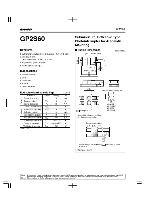
NOTICEq The circuit application examples in this publication are provided to explain representative applications of SHARP devices and are not intended to guarantee any circuit design or license any intellectual property rights. SHARP takes no responsibility for any problems related to any intellectual property right of a third party resulting from the use of SHARP's devices.q Contact SHARP in order to obtain the latest device specification sheets before using any SHARP device. SHARP reserves the right to make changes in the specifications, characteristics, data, materials, structure, and other contents described herein at any time without notice in order to improve design or reliability. Manufacturing locations are also subject to change without notice.q Observe the following points when using any devices in this publication. SHARP takes no responsibility for damage caused by improper use of the devices which does not meet the conditions and absolute maximum ratings to be used specified in the relevant specification sheet nor meet the following conditions:(i)The devices in this publication are designed for use in general electronic equipment designs such as:--- Personal computers--- Office automation equipment--- Telecommunication equipment [terminal]--- Test and measurement equipment--- Industrial control--- Audio visual equipment--- Consumer electronics(ii)Measures such as fail-safe function and redundant design should be taken to ensure reliability and safety when SHARP devices are used for or in connection with equipment that requires higher reliability such as:--- Transportation control and safety equipment (i.e., aircraft, trains, automobiles, etc.)--- Traffic signals--- Gas leakage sensor breakers--- Alarm equipment--- Various safety devices, etc.(iii)SHARP devices shall not be used for or in connection with equipment that requires an extremely high level of reliability and safety such as:--- Space applications--- Telecommunication equipment [trunk lines]--- Nuclear power control equipment--- Medical and other life support equipment (e.g., scuba).q Contact a SHARP representative in advance when intending to use SHARP devices for any "specific" applications other than those recommended by SHARP or when it is unclear which category mentioned above controls the intended use.q If the SHARP devices listed in this publication fall within the scope of strategic products described in the Foreign Exchange and Foreign Trade Control Law of Japan, it is necessary to obtain approval to export such SHARP devices. q This publication is the proprietary product of SHARP and is copyrighted, with all rights reserved. Under the copyright laws, no part of this publication may be reproduced or transmitted in any form or by any means, electronic or mechanical, for any purpose, in whole or in part, without the express written permission of SHARP. Express written permission is also required before any use of this publication may be made by a third party.q Contact and consult with a SHARP representative if there are any questions about the contents of this publication.。
INFINEON IKP20N60T 说明书
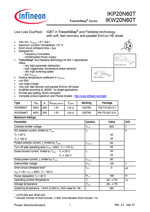
Low Loss DuoPack : IGBT in TrenchStop® and Fieldstop technologywith soft, fast recovery anti-parallel EmCon HE diode•Very low V CE(sat) 1.5 V (typ.)•Maximum Junction Temperature 175 °C•Short circuit withstand time – 5µs•Designed for :- Frequency Converters- Uninterrupted Power Supply•TrenchStop® and Fieldstop technology for 600 V applicationsoffers :- very tight parameter distribution- high ruggedness, temperature stable behavior- very high switching speed-lowV CE(sat)•Positive temperature coefficient in V CE(sat)• Low EMI•Low Gate Charge•Very soft, fast recovery anti-parallel EmCon HE diode•Qualified according to JEDEC1 for target applications•Pb-free lead plating; RoHS compliant•Complete product spectrum and PSpice Models :/igbt/Type V CE I C V CE(sat),Tj=25°C T j,max Marking PackageIKP20N60T 600V 20A 1.5V 175°C K20T60 PG-TO-220-3-1IKW20N60T 600V 20A 1.5V 175°C K20T60 PG-TO-247-3-21Maximum RatingsParameter SymbolValueUnit Collector-emitter voltage V C E600 VDC collector current, limited by T jmax T C = 25°CT C = 100°C I C4020Pulsed collector current, t p limited by T jmax I C p u l s60 Turn off safe operating area (V CE ≤ 600V, T j≤ 175°C) -60Diode forward current, limited by T jmax T C = 25°CT C = 100°C I F4020Diode pulsed current, t p limited by T jmax I F p u l s60AGate-emitter voltage V G E±20 VShort circuit withstand time2)V GE = 15V, V CC ≤ 400V, T j≤ 150°Ct S C 5 µsPower dissipation T C = 25°C P t o t166 W Operating junction temperature T j-40...+175Storage temperature T s t g-55...+175Soldering temperature, 1.6mm (0.063 in.) from case for 10s - 260°C1 J-STD-020 and JESD-0222) Allowed number of short circuits: <1000; time between short circuits: >1s.PG-TO-220-3-1Thermal Resistance Parameter Symbol Conditions Max. Value UnitCharacteristicIGBT thermal resistance, junction – caseR t h J C0.9 Diode thermal resistance, junction – case R t h J C D 1.5 Thermal resistance, junction – ambient R t h J A 6240K/WElectrical Characteristic, at T j = 25 °C, unless otherwise specifiedValue Parameter Symbol Conditions min. Typ. max. UnitStatic CharacteristicCollector-emitter breakdown voltage V (B R )C E S V G E =0V, I C =0.2mA 600 - - Collector-emitter saturation voltageV C E (s a t )V G E = 15V, I C =20A T j =25°C T j =175°C- - 1.5 1.9 2.05 - Diode forward voltageV FV G E =0V, I F =20A T j =25°C T j =175°C- - 1.65 1.6 2.05 - Gate-emitter threshold voltage V G E (t h ) I C =290µA,V C E =V G E 4.1 4.9 5.7V Zero gate voltage collector currentI C E S V C E =600V , V G E =0V T j =25°C T j =175°C- -- -40 1000µAGate-emitter leakage current I G E S V C E =0V,V G E =20V - - 100 nA Transconductance g f s V C E =20V, I C =20A - 11 - S Integrated gate resistor R G i n t- ΩDynamic Characteristic Input capacitance C i s s - 1100 - Output capacitanceC o s s - 71-Reverse transfer capacitance C r s s V C E =25V, V G E =0V, f =1MHz-32- pFGate chargeQ G a t e V C C =480V, I C =20A V G E =15V - 120 - nC Internal emitter inductancemeasured 5mm (0.197 in.) from case L E TO-247-3-21 TO-220-3-1 - 13 7- nHShort circuit collector current 1)I C (S C )V G E =15V,t S C ≤5µsV C C = 400V, T j ≤ 150°C- 183.3 - A1) Allowed number of short circuits: <1000; time between short circuits: >1s.2)Leakage inductance L σ and Stray capacity C σ due to dynamic test circuit in Figure E.Switching Characteristic, Inductive Load, at T j =25 °CValueParameter Symbol Conditions min. Typ. max. UnitIGBT Characteristic Turn-on delay time t d (o n ) - 18 - Rise timet r - 14 - Turn-off delay time t d (o f f ) - 199 - Fall time t f - 42 - ns Turn-on energy E o n - 0.31 - Turn-off energy E o f f - 0.46 - Total switching energyE t sT j =25°C,V C C =400V,I C =20A,V G E =0/15V, R G =12 Ω, L σ2)=131nH, C σ2)=31pFEnergy losses include “tail” and diode reverse recovery.- 0.77 -mJ Anti-Parallel Diode Characteristic Diode reverse recovery time t r r - 41 - ns Diode reverse recovery charge Q r r - 0.31 - µC Diode peak reverse recovery current I r r m- 13.3 - A Diode peak rate of fall of reverse recovery current during t bdi r r /dtT j =25°C,V R =400V, I F =20A, di F /dt =880A/µs- 711 - A/µsSwitching Characteristic, Inductive Load, at T j =175 °CValueParameter Symbol Conditions min. Typ. max. UnitIGBT Characteristic Turn-on delay time t d (o n ) - 18 - Rise timet r - 18 - Turn-off delay time t d (o f f ) - 223 - Fall time t f - 76 - ns Turn-on energy E o n - 0.51 - Turn-off energy E o f f - 0.64 - Total switching energyE t s T j =175°C,V C C =400V,I C =20A,V G E =0/15V, R G = 12 Ω L σ1)=131nH, C σ1)=31pFEnergy losses include “tail” and diode reverse recovery. - 1.15 - mJ Anti-Parallel Diode Characteristic Diode reverse recovery time t r r - 176 - ns Diode reverse recovery charge Q r r - 1.46 - µC Diode peak reverse recovery current I r r m- 18.9 - A Diode peak rate of fall of reverse recovery current during t bdi r r /dtT j =175°CV R =400V, I F =20A, di F /dt =880A/µs- 467 - A/µs1)Leakage inductance L σ and Stray capacity C σ due to dynamic test circuit in Figure E.I C , C O L L E C T O R C U R R E N T10Hz100Hz1kHz10kHz100kHz0A 10A 20A 30A 40A 50A 60AI C , C O L L E C T O R C U R R E N T1V10V100V 1000V0.1A1A10Af , SWITCHING FREQUENCYV CE , COLLECTOR -EMITTER VOLTAGEFigure 1. Collector current as a function ofswitching frequency(T j ≤ 175°C, D = 0.5, V CE = 400V, V GE = 0/+15V, R G = 12Ω) Figure 2. Safe operating area(D = 0, T C = 25°C, T j ≤175°C; V GE =15V)P t o t , P O W E R D I S S I P A T I O N25°C50°C 75°C 100°C 125°C 150°C0W 20W 40W 60W 80W 100W 120W 140W160W I C , C O L L E C T O R C U R R E N T0A5A 10A 15A 20A 25A 30AT C , CASE TEMPERATURET C , CASE TEMPERATUREFigure 3. Power dissipation as a function ofcase temperature (T j ≤ 175°C)Figure 4. Collector current as a function ofcase temperature(V GE ≥ 15V, T j ≤ 175°C)I C , C O L L E C T O R C U R R E N T0V1V2V3V0A10A 20A30A40A50AI C , C O L L E C T O R C U R R E N T0V1V2V 3V 4V0A10A20A30A40A50AV CE , COLLECTOR -EMITTER VOLTAGEV CE , COLLECTOR -EMITTER VOLTAGEFigure 5. Typical output characteristic(T j = 25°C)Figure 6. Typical output characteristic(T j = 175°C)I C , C O L L E C T O R C U R R E N T0A5A 10A 15A 20A 25A 30A 35AV C E (s a t ), C O L L E C T O R -E M I T T S A T U R A T I O N V O L T A G E0°C50°C100°C150°C0.0V0.5V1.0V1.5V2.0V2.5VV GE , GATE-EMITTER VOLTAGET J , JUNCTION TEMPERATUREFigure 7. Typical transfer characteristic(V CE =10V)Figure 8. Typical collector-emittersaturation voltage as a function of junction temperature (V GE = 15V)t , S W I T C H I N G T I M E S0A 5A 10A 15A 20A 25A 30A 35At , S W I T C H I N G T I M E S10Ω20Ω30Ω40Ω50Ω60Ω70ΩI C , COLLECTOR CURRENTR G , GATE RESISTORFigure 9. Typical switching times as afunction of collector current (inductive load, T J =175°C,V CE = 400V, V GE = 0/15V, R G = 12Ω, Dynamic test circuit in Figure E) Figure 10. Typical switching times as afunction of gate resistor (inductive load, T J = 175°C,V CE = 400V, V GE = 0/15V, I C = 20A, Dynamic test circuit in Figure E)t , S W I T C H I N G T I M ES25°C50°C75°C100°C 125°C 150°CV G E (t h ), G A T E -E M I T T T R S H O L D V O L T A GE-50°C0°C 50°C 100°C 150°CT J , JUNCTION TEMPERATURET J , JUNCTION TEMPERATUREFigure 11. Typical switching times as afunction of junction temperature (inductive load, V CE = 400V, V GE = 0/15V, I C = 20A, R G =12Ω, Dynamic test circuit in Figure E)Figure 12. Gate-emitter threshold voltage asa function of junction temperature (I C = 0.29mA)E , S W I T C H I N G E N E R G Y L O S S E S0A5A10A15A20A25A30A35A0.0mJ0.4mJ0.8mJ1.2mJ1.6mJ2.0mJ 2.4mJE , S W I T C H I N G E N E R G Y L O S S E S0Ω15Ω30Ω45Ω60Ω0.0m0.4m 0.8m 1.2m 1.6m 2.0m 2.4mI C , COLLECTOR CURRENTR G , GATE RESISTORFigure 13. Typical switching energy lossesas a function of collector current (inductive load, T J = 175°C,V CE = 400V, V GE = 0/15V, R G = 12Ω, Dynamic test circuit in Figure E) Figure 14. Typical switching energy lossesas a function of gate resistor (inductive load, T J = 175°C,V CE = 400V, V GE = 0/15V, I C = 20A, Dynamic test circuit in Figure E)E , S W I T C H I N G E N E R G Y L O S S E S25°C50°C 75°C 100°C 125°C 150°C0.0mJ0.2mJ0.4mJ0.6mJ0.8mJ1.0mJE , S W I T C H I N G E N E R G Y L O S S E S0.0m 0.2m 0.4m 0.6m 0.8m 1.0m 1.2m 1.4m 1.6m 1.8m 2.0mT J , JUNCTION TEMPERATUREV CE , COLLECTOR -EMITTER VOLTAGEFigure 15. Typical switching energy lossesas a function of junction temperature(inductive load, V CE = 400V,V GE = 0/15V, I C = 20A, R G = 12Ω, Dynamic test circuit in Figure E)Figure 16. Typical switching energy lossesas a function of collector emitter voltage(inductive load, T J = 175°C,V GE = 0/15V, I C = 20A, R G = 12Ω, Dynamic test circuit in Figure E)V G E , G A T E -E M I T TE R V O L T A G E0V5V10V15Vc , C A P A C I T A NC EQ GE , GATE CHARGEV CE , COLLECTOR -EMITTER VOLTAGEFigure 17. Typical gate charge(I C =20 A)Figure 18. Typical capacitance as a functionof collector-emitter voltage (V GE =0V, f = 1 MHz)I C (s c ), s h o r t c i r c u i t C O L L E C T O R C U R R E N T12V14V 16V 18V0A 50A 100A 150A 200A 250A 300A t S C , S H O R T C I R C U I T W I T H ST A N D T I M E10V11V 12V 13V 14V0µs2µs4µs6µs8µs10µs12µsV GE , GATE -EMITTETR VOLTAGEV GE , GATE -EMITETR VOLTAGEFigure 19. Typical short circuit collectorcurrent as a function of gate-emitter voltage(V CE ≤ 400V, T j ≤ 150°C)Figure 20. Short circuit withstand time as afunction of gate-emitter voltage (V CE =600V , start at T J =25°C, T Jmax <150°C)Z t h J C , T R A N S I E N T T H E R M A L R E S I S T A N C E1µs 10µs 100µs 1ms 10ms 100ms10-2K/W10-1K/WZ t h J C , T R A N S I E N T T H E R M A L R E S I S T A N C E1µs10µs 100µs 1ms 10ms 100ms10-210-1100t P , PULSE WIDTHt P , PULSE WIDTHFigure 21. IGBT transient thermal resistance(D = t p / T )Figure 22. Diode transient thermalimpedance as a function of pulse width (D =t P /T )t r r , R E V E R S E R E C O V E R Y T I M E0ns50ns100ns150ns200ns250nsQ r r , R E V E R S E R E C O V E R Y C H A R G E600A/µs900A/µs1200A/µs0.2µC0.4µC 0.6µC 0.8µC 1.0µC 1.2µC 1.4µC 1.6µC1.8µCdi F /dt , DIODE CURRENT SLOPEdi F /dt , DIODE CURRENT SLOPEFigure 23. Typical reverse recovery time asa function of diode current slope (V R =400V, I F =20A,Dynamic test circuit in Figure E)Figure 24. Typical reverse recovery chargeas a function of diode current slope(V R = 400V, I F = 20A,Dynamic test circuit in Figure E)I r r , R E V E R S E R E C O V E R Y C U R R E N T600A/µs 900A/µs 1200A/µs0A4A 8A 12A 16A20A 24Ad i r r /d t , D I O D E P E A K R A T E O F F A L L O F R E V E R S E R E C O V E R Y C U R R E NTdi F /dt , DIODE CURRENT SLOPEdi F /dt , DIODE CURRENT SLOPEFigure 25. Typical reverse recovery currentas a function of diode current slope(V R = 400V, I F = 20A,Dynamic test circuit in Figure E) Figure 26. Typical diode peak rate of fall ofreverse recovery current as a function of diode current slope (V R =400V, I F =20A,Dynamic test circuit in Figure E)I F , F O R W A R D C U R R E NT0V 1V 2V0A10A20A30A40A50AV F , F O R W A R D V O L T A G E0°C50°C 100°C 150°C0.0V0.5V1.0V1.5V2.0VV F , FORWARD VOLTAGET J , JUNCTION TEMPERATUREFigure 27. Typical diode forward current asa function of forward voltageFigure 28. Typical diode forward voltage as afunction of junction temperaturePG-TO-220-3-1PG-TO247-3-21Edition 2006-01Published byInfineon Technologies AG81726 München, Germany© Infineon Technologies AG 9/12/07.All Rights Reserved.Attention please!The information given in this data sheet shall in no event be regarded as a guarantee of conditions or characteristics (“Beschaffenheitsgarantie”). With respect to any examples or hints given herein, any typical values stated herein and/or any information regarding the application of the device, Infineon Technologies hereby disclaims any and all warranties and liabilities of any kind, including without limitation warranties of non-infringement of intellectual property rights of any third party.InformationFor further information on technology, delivery terms and conditions and prices please contact your nearest Infineon Technologies Office ().WarningsDue to technical requirements components may contain dangerous substances. For information on the types in question please contact your nearest Infineon Technologies Office.Infineon Technologies Components may only be used in life-support devices or systems with the express written approval of Infineon Technologies, if a failure of such components can reasonably be expected to cause the failure of that life-support device or system, or to affect the safety or effectiveness of that device or system. Life support devices or systems are intended to be implanted in the human body, or to supportand/or maintain and sustain and/or protect human life. If they fail, it is reasonable to assume that the health of the user or other persons may be endangered.。
手机专业知识培训资料

*#06# 查询IMEI号码,*#7780# 格式化手机,*#0000#查询当前软件版本号
2、苹果:原称苹果电脑(Apple Computer),2007年1月9日 于旧金山的Macworld Expo上宣布改名。总部位于美国加 利福尼亚的库比提诺,核心业务是电子科技产品,苹果的 Apple II于1970年代助长了个人电脑革命,其后的 Macintosh接力于1980年代持续发展。最知名的产品是其 出品的iPod、Macbook、Macbook Pro、Macbook Air、 iPhone和数位音乐播放器和iTunes音乐商店,它在高科技 企业中以创新而闻名。
Android系统简介
Android 2.1主要特性:提升硬件速度,更多屏幕以及分辨率选择,大幅度的用户界面改 良支持,Exchange活动墙纸,大幅改进虚拟键盘蓝牙,2.1Google 地图 Android 2.2主要特性:整体性能大幅度的提升,3G网络共享功能,Flash的支持, App2sd功能,全新的软件商店,更多的Web应用API接口的开发 Android 2.3主要特性:简化界面、速度提升,更快更直观的文字输入,一键文字选择和 复制/粘帖,改进的电源管理系统,新的应用管理方式,原生支持前置摄像头、互联网通 话和NFC,增加下载管理器,系统原生支持VoIP
3、HTC:即宏达国际电子股份有限公司),是一家 全球知名的科技公司,主要产品为智能手机,公 司总部位于中国台湾省桃园县。HTC公司于1997 年由王雪红、卓火土,与总经理兼执行长周永明 所创立。自成立以来,该公司已经发展出强大的 研发能力、开创了许多全新的设计和产品的创新 。
HTC历史简介
HTC是国际性的代工厂,其销售客户群着眼全球,我们常见的包括:中国多普达、英国 O2、法国Orange 、德国T-Mobile、北美AT&T、沃达丰等
Samsung 6000 6020 Series Laundry Product Guide

Product Guide6000/6020 Series LaundryWF45T6000AW – WasherDVE45T6020W – Electric Long Vent DryerDVG45T6020W – Gas Long Vent DryerTable of ContentsProduct Overview Product Overview 4Carousel Image Order 5Product Messaging Features and Benefits 7Product Specs Related Products 13Spec Sheet14Energy Guide and User Manual 15Feature Icons17WF45T6000AW – Front Load WasherProduct OverviewProduct Overview 19Carousel Image Order 20Product MessagingFeatures and Benefits 22Product SpecsRelated Products 27Spec Sheet 28User Manual 29Feature Icons31DVE45T6020W - Front Load Electric Long Vent Dryer DVG45T6020W - Front Load Gas Long Vent DryerProduct OverviewWF45T6000AW – 4.5 cu. ft. Front Load Washerwith Vibration Reduction Technology+Product OverviewProduct Long Description (299 Characters)Samsung’s ENERGY STAR ® Certified Front Load washer has 4.5 cu. ft. capacity to fit more in every load and cut down on laundry time. It is equipped with Vibration Reduction Technology+ to reduce noise for quiet washing and features Self Clean+ to eliminate 99% of bacteria that can form in the drum.11Based on testing by Intertek of the Self Clean+ cycle on the WF6000R.Product Short Description (127 Characters)Samsung’s Front Load washer offers Vibration Reduction Technology+ and Self Clean+ to eliminate 99% of bacteria from the drum.1Product Title4.5 cu. ft. Front Load Washer with Vibration Reduction Technology+Available ColorWhiteModel Number: WF45T6000AW UPC: 887276394794123461112891075: /mm/nicePath/easyads?nav=pr658559408 : /mm/nicePath/easyads?nav=pr658559385Product MessagingWF45T6000AW – 4.5 cu. ft. Front Load Washerwith Vibration Reduction Technology+N/AEasy Ads links: /mm/nicePath/easyads?nav=pr658559409 /mm/nicePath/easyads?nav=pr658559386Product SpecsWF45T6000AW – 4.5 cu. ft. Front Load Washer with Vibration Reduction Technology+Related ProductsSpec SheetEasy Ads link /mm/nicePath/easyads?nav=pr658559288Vibration Reduction Technology+Rating ENERGY STAR ®-rated CEE Tier 2IMEF = 2.95Features• 4.5 cu. ft. Capacity • V ibration Reduction Technology+• Self Clean+1• S mart Care • 10 Preset Washing Cycles • 6 Additional Washing Options • 5 Temperature Levels • L ED Display: Ice Blue Available Color White Self Clean+Washer Spec Sheet - front Washer Spec Sheet - backEnergy Guide and User ManualEasy Ads link/mm/nicePath/easyads?nav=pr658559288WasherU ser manualW F45T6000A*Energy Guide User ManualUntitled-7 14/2/2020 2:56:32 PMFeature IconsWF45T6000AW – 4.5 cu. ft. Front Load Washer with Vibration Reduction Technology+Feature IconsSmart Care Large 4.5 cu. ft.CapacityVibration ReductionTechnology+ENERGY STAR®CertifiedSelf Clean+Product OverviewDVE45T6020W & DVG45T6020W - 7.5 cu. ft. Front Load Long Vent Dryer with Sensor DryProduct OverviewProduct Long Description (278 Characters)Samsung’s newest long vent dryer, with up to 120-foot venting ability, features Sensor Dry, which optimizes cycle time and temperature to thoroughly and safely dry your clothes. And, with its 7.5 cu. ft. capacity and 10 preset drying cycles, you can do fewer loads in less time.Product Short Description (103 Characters)Samsung’s 7.5 cu. ft. capacity dryer’s long hose vents up to 120 feet, for more flexible installation.Product Title7.5 cu. ft. Electric (Gas) Long Vent Dryer with Sensor DryAvailable ColorWhite Model Number: DVE45T6020W UPC: 887276438153Model Number: DVG45T6020W UPC: 8872764381601234789101112: /mm/nicePath/easyads?nav=pr658559838 : /mm/nicePath/easyads?nav=pr658559804Product MessagingDVE45T6020W & DVG45T6020W - 7.5 cu. ft. Front LoadLong Vent Dryer with Sensor DryProduct SpecsDVE45T6020W & DVG45T6020W - 7.5 cu. ft. Front Load Long Vent Dryer with Sensor DryRelated ProductsSpec SheetsFeatures• Sensor Dry• 7.5 cu. ft. Large Capacity 7.5 cu. ft. Large CapacitySensor DryAvailable ColorWhiteElectrical Requirements:- 120V / 60Hz - 15 AmpsEasy Ads link/mm/nicePath/easyads?nav=pr658844097Gas Dryer Spec Sheet - front Gas Dryer Spec Sheet - backElectric Dryer Spec Sheet - front Electric Dryer Spec Sheet - back Features• Sensor Dry• 7.5 cu. ft. Large Capacity Rating:644 kWh/yr7.5 cu. ft. Large CapacitySensor DryAvailable ColorWhiteElectrical Requirements:Easy Ads link/mm/nicePath/easyads?nav=pr658844097User Manual Easy Ads linkDryerUser manualDVE(G)45T6005*/DVE(G)45T6000*Feature IconsDVE45T6020W & DVG45T6020W - 7.5 cu. ft. Front Load Long Vent Dryer with Sensor DryFeature IconsDryer:Icons Smart Care Sensor Dry Large 7.5 cu. ft. Capacity Lint Filter Indicator10 Preset Drying Cycles Interior Drum Light Long Vent Drying。
FPGA可编程逻辑器件芯片EP2S60F1020C3中文规格书
3.Configuration & TestingIEEE Std. 1149.1 JTAG Boundary-Scan Support All Stratix®II devices provide Joint Test Action Group (JTAG) boundary-scan test (BST) circuitry that complies with the IEEEStd.1149.1. JTAG boundary-scan testing can be performed either before or after, but not during configuration. Stratix II devices can also use the JTAG port for configuration with the Quartus®II software or hardware using either Jam Files (.jam) or Jam Byte-Code Files (.jbc).Stratix II devices support IOE I/O standard setting reconfiguration through the JTAG BST chain. The JTAG chain can update the I/O standard for all input and output pins any time before or during user mode through the CONFIG_IO instruction. You can use this capability for JTAG testing before configuration when some of the Stratix II pins drive or receive from other devices on the board using voltage-referenced standards. Because the Stratix II device may not be configured before JTAG testing, the I/O pins may not be configured for appropriate electrical standards for chip-to-chip communication. Programming those I/O standards via JTAG allows you to fully test I/O connections to other devices.A device operating in JTAG mode uses four required pins, TDI,TDO, TMS, and TCK, and one optional pin, TRST. The TCK pin has an internal weak pull-down resistor, while the TDI,TMS and TRST pins have weak internal pull-ups. The JTAG input pins are powered by the 3.3-V VCCPD pins. The TDO output pin is powered by the V CCIO power supply of bank 4.Stratix II devices also use the JTAG port to monitor the logic operation of the device with the SignalTap®II embedded logic analyzer. Stratix II devices support the JTAG instructions shown in Table3–1.1Stratix II, Stratix, Cyclone®II, and Cyclone devices must be within the first 17 devices in a JTAG chain. All of these deviceshave the same JTAG controller. If any of the Stratix II, Stratix,Cyclone II, or Cyclone devices are in the 18th of further position,they fail configuration. This does not affect SignalTap II.The Stratix II device instruction register length is 10 bits and the USERCODE register length is 32 bits. Tables3–2 and 3–3 show the boundary-scan register length and device IDCODE information for Stratix II devices.Document Revision HistoryStratix II Device Handbook, Volume 1Pin CapacitanceTable 5–32 shows the Stratix II device family pin capacitance.Table 5–31.Series & Differential On-Chip Termination Specification for Left & Right I/O BanksSymbolDescriptionConditionsResistance ToleranceCommercial Max IndustrialMaxUnit25-Ω R S 3.3/2.5Internal series termination without calibration (25-Ω setting )V C C I O = 3.3/2.5 V ±30±30%50-Ω R S 3.3/2.5/1.8Internal series termination without calibration (50-Ω setting )V C C I O = 3.3/2.5/1.8 V ±30±30%50-Ω R S 1.5Internal series termination without calibration (50-Ω setting )V C C I O = 1.5 V±36±36%R DInternal differential termination forLVDS or HyperT ransport technology (100-Ω setting )V C C I O = 2.5 V ±20±25%Table 5–32.Stratix II Device Capacitance Note (1)SymbolParameterTypicalUnitC I OT B Input capacitance on I/O pins in I/O banks 3, 4, 7, and 8.5.0pF C I O L R Input capacitance on I/O pins in I/O banks 1, 2, 5, and 6, including high-speed differential receiver and transmitter pins.6.1pF C C L K T B Input capacitance on top/bottom clock input pins: CLK[4..7] and CLK[12..15].6.0pF C C L K L R Input capacitance on left/right clock inputs: CLK0, CLK2, CLK8, CLK10. 6.1pF C C L K L R +Input capacitance on left/right clock inputs: CLK1, CLK3, CLK9, and CLK11.3.3pF C O U T F BInput capacitance on dual-purpose clock output/feedback pins in PLL banks 9, 10, 11, and 12.6.7pFNote to Table 5–32:(1)Capacitance is sample-tested only. Capacitance is measured using time-domain reflections (TDR). Measurement accuracy is within ±0.5pFTiming ModelFigure5–6.Measurement Setup for t zxTable5–35 specifies the input timing measurement setup.Table5–35.Timing Measurement Methodology for Input Pins(Part 1 of2)Notes(1)–(4)I/O StandardMeasurement Conditions Measurement Point V CCIO (V)V REF (V)Edge Rate (ns)V M E A S (V)LVTTL (5) 3.135 3.135 1.5675 LVCMOS (5) 3.135 3.135 1.5675 2.5 V (5) 2.375 2.375 1.1875 1.8 V (5) 1.710 1.7100.855 1.5 V (5) 1.425 1.4250.7125 PCI (6) 2.970 2.970 1.485 PCI-X (6) 2.970 2.970 1.485 SSTL-2 Class I 2.325 1.163 2.325 1.1625 SSTL-2 Class II 2.325 1.163 2.325 1.1625 SSTL-18 Class I 1.6600.830 1.6600.83 SSTL-18 Class II 1.6600.830 1.6600.83 1.8-V HSTL Class I 1.6600.830 1.6600.83。
S60配置
P P P P / S S / S S S S S S S S / / S S / S S S S / S O S S / S S S / S S S S S S S S S S O
S S S S / S S / S S S S S S S S S / S / S S S S S / S O S S S S S S S S S S S S S S S / S O
1537 S S S S S S S S S S O O O S S S S O O O S S S S S S S S S
1550 S S S S S S S S S S O O O S S S S S S S S S
ASC预先稳定控制系统 CTC弯道稳定控制系统 EDC发动机牵引力控制系统 TSC拖车稳定控制系统 EBA紧急制动辅助系统,制动灯频闪警示 City Safety城市安全系统
S S S S S S S / /
S S S S S S S S /
S S S S S S / / S
S60技术参数表
车型
发动机 排量 变速箱 最大功率(hp(kw)/rpm) 最大扭扭(Nm/rpm) 油耗(L/100km),混合工况 最高车速(km/h) 加速性能((0-100km/h)s) 底盘悬挂 驱动形式 制动系统 轮圈和轮胎 燃油和排放 油箱容积 长度(mm) 宽度(mm) 高度 轴距 轮距(前、后)(mm) 行李箱容积 整备质量(Kg) 安全配备 Volvo 车内监控防盗系统 IDIS智能驾驶员信息系统 前排双安全气囊 前排侧安全气囊 前后一体式安全气帘 前排头颈保护系统 前排乘客安全气囊关闭功能 行李箱安全锁止功能 全座带预紧力装置安全带 后方停车辅助系统 前后方停车辅助系统 后方可视影像停车辅助系统 BLIS盲点信息系统 Isofix儿童座椅固定装置 ABS制动防抱死系统 DSTC动态稳定和牵引力控制系统
Line 6 Spider V 20音箱操作指南说明书

SPIDER V 20PILOT’S GUIDE40-00-0395 Rev A Pilot’s Guide also available at /manuals © 2017 Line 6, Inc.MANUEL DE PILOTAGEPILOTENHANDBUCH MANUAL DEL PILOTO パイロット・ガイド新手指南For details on other Spider V amplifier models, please see the Spider V Family Pilot's Guide, available at /manuals.Welcome to the descriptions of the Line 6®functionality.The SPIDER V 20 SPIDER Familya compact combo form factor features of the SPIDER V 20 Features:•use of the Spider V Remote• Extended-range speakerelectric guitar•• Built-in T uner•••free Spider V Remote•and PC computers• Stereo headphone output••and parameters••••backup at any time1. INPUT Jack – Plug in your guitar here.2. PRESET Encoder – T urn to select one of the 16 available presets. Apreset stores the value of each knob, as well as the FX 1, 2 & 3 model types and their bypass states.3. DRIVE Knob – Drive is like the volume or gain knob on other amps;it controls how much “dirt” or “distortion” you get in your sound. 4. TONE Knob –This knob is a macro control for the overall tonalsettings for each amp, utilizing bass, mid and treble controls under-the-hood. T urn this down for a warmer tone, or up for a brighter sound, with a flatter or "scooped" sound at 12 o'clock.5. VOLUME Knob – Controls the volume of the preset independentlyof the MASTER Volume Knob. Use this knob to match volumes between presets.6. REVERB Knob – Controls the mix and depth of the Reverb effect.T urn it up or down for more or less ambience.7. FX Knob – Controls how much of each of the three enabled on-board effects are applied. T o adjust a particular effect amount, select and enable the desired effect using the three FX Buttons.8. FX 1, 2 & 3 Buttons – These buttons select and control the bypassstate of the three on-board effects. The FX Knob controls how much of the currently selected effect is applied to the sound.There are five different types of effects available, with each type displaying a corresponding color: yellow for Dynamics/Compression, orange for Distortion, blue for Modulation, green for Delay/Echo, and purple for Filter/Pitch/Synth.9. SAVE Button – Press to store the values of the knobs and state ofthe FX buttons within the currently selected preset.10. T AP/TUNER Button – T apping this button a few times sets thetempo of your delay and modulation effects in use.Pressing and holding this button for 2 seconds engages the T uner.The T uner mutes the guitar signal and utilizes the three FX Buttons' lights to indicate your pitch by displaying red on the left (flat), red on the right (sharp) or green in the middle (in-tune). Press the T AP/ TUNER button once to exit the T uner.11. MASTER Volume Knob – Y ou can choose the overall volume of theamplifier (or headphones, if connected), without affecting the overall tone or saturation. Always start with the MASTER knob set to minimum!12. PHONES Output – Connect a pair of headphones here. When youdo so, the speaker is muted. This jack also doubles as a direct output.Use a stereo TRS cable to connect to a mixer or recording device.13. USB (Micro B connector) – Connect a Mac, PC, iOS device (withApple USB Camera Connection Kit) or Android device (with OTG adapter), to edit tones using the Spider V Remote application, or to playback and record audio.Controls and ConnectionsAC PowerThe amplifier's Power Switch and AC Connector, for use with the included power cable, are located on the rear panel of the amplifier.Changing PresetsT urn the PRESET Encoder to choose the desired preset. Each preset is designed for a particular style or application and includes one type of amp model, the 3 Smart FX and their settings.Editing Your ToneSelect the preset from which you wish to base your tone and use the knobs and buttons to modify the sound to your liking (see "Controls and Connections" for details). The Drive, T one, Volume, Reverb amount, Effects amounts and their bypass states can all be modified using the controls on the front panel of the amplifier. Y ou can utilize the Spider V Remote editor application to further modify the type of amp or effects you want to use within the preset.Saving PresetsSave your settings to the current PRESET Encoder location by pressing the SAVE button once. The SAVE button will blink twice to indicate the preset is now saved. Y ou can utilize the Spider V Remote app to copy or rearrange your presets.Using Smart FXThe SPIDER V 20 amplifier includes a built-in Reverb effect as well at 3 assignable Smart FX per preset.The assignable Smart FX types are Dynamics (yellow), Drives (orange), Modulation (blue), Delay (green), and Filter/Pitch/Synth (purple). There are multiple models to choose from for each effect type. Y ou can utilize the Spider V Remote app to change the effect type or model.1. Press the FX Buttons 1-3to turn each effect on or off. Whenilluminated brightly, the effect is on (enabled). When an effect is off (bypassed), it is lit dimly.2. The FX Knob controls how much of the effects are being applied.This only applies to whichever effects that are currently enabled, all at once. T o modify only a single effect's amount, turn off the other two effects. This control functions in a relative manner, so you may have to move it back and forth to find the right amount.3.Once you are pleased with the amount of the effects, press theSAVE Button to retain these settings as part of the preset. Using the Spider V Remote Application for Mac & PC Spider V Remote is a FREE editor and librarian application for Mac and PC, available at /software. T o connect a Spider V 20 amp to your computer, use a standard USB-A to USB-Micro B cable or adapter (not included). Simply install and launch the application and it will automatically sync up with your Spider V 20 amplifier.*NOTE: For USB operation with Windows®computers, it is necessary to install the latest Line 6 Spider V ASIO driver from /software. There is no driver installation necessary for Mac computers.Application OverviewThe application displays a preset's contents within its three panels: the Signal Flow, Model Browser and Editor panels. The Signal Flow panel shows the various types of "blocks" that make up the current preset. All available amp & effects models are selectable within the Model Browser, arranged by type. All available parameters for the currently-selected block appear within the Editor, located in the lower right pane. T o edit a parameter value, click and drag on the slider handles within the Editor panel.Changing Amps and EffectsT o change the model for any amp or effects block, select the block within the Signal Flow, then choose the desired model from the Model Browser. Loading and Saving PresetsT o save your tone from within the application, click the LOAD/SAVE button and select Save T one to SPIDER V 20. The current preset slot will be highlighted. Alternatively, you may select a different save destination slot if desired. Click Save to complete the operation. T o follow are additional options available from this menu for managing your Preset Library.• Save T one to Spider V 20 – Saves the tone with all its current settings to a preset slot of your choosing.• Save T one to Disk – Saves the current tone to a folder on disk as an .l6p tone file.• Load T one – Loads a tone from disk, but does not save the tone to the current preset slot.• Import T one to Spider V 20 – Loads a .l6p tone file from disk and saves it to a preset slot of the of your choosing.• Export T one from Spider V 20 – Saves a different tone than the one currently loaded to a folder on disk.• Back Up Spider V 20 to File – Creates a "bundle" backup file which includes all the tones currently loaded on your Spider V 20 amp and saves the file to disk.• Restore Spider V 20 from File – Overwrites all presets on your Spider V 20 amp with the tones in the backup file from disk. Using Spider V Remote App on iOS and Android Devices Spider V Remote is also offered as a FREE editor, librarian and updater app for iOS and Android mobile devices. The functionality of the mobile application is very similar to that of the Spider V Remote Mac & PC application (please see preceding section).For iOS Devices -An Apple USB Camera Connection Kit adapter is required for connecting to your Spider V 20 amp's USB port. The Spider V Remote mobile app is available free from the Apple App Store.For Android Devices -An Android "On-The-Go" (OTG) Adapter is required for connecting to your Spider V 20 amp's USB port. The Spider V Remote mobile app is available free from the Google Play™ store.Steinberg Cubase® LE Recording SoftwareT o get your FREE copy of Steinberg Cubase LE software for Mac or PC, please register your Spider V 20 amplifier at https:///account/ registergear/. Once registered, you'll receive a software activation code and download link on the online registration page.Spider V 20 Amplifier Firmware UpdatesFor optimal performance, always run the latest firmware in your Spider V 20 amplifier. The Spider V Remote mobile application will inform you whenever a firmware update is available, so you'll always know you have the latest version! If a firmware update is available, you can perform the update from within the Spider V Remote mobile application - just follow the prompts to complete the update on your connected Spider V 20 amplifier.If your Spider V 20 amp is connected to a Mac or Windows computer, you'll need use the Line 6 Updater application to check for and perform firmware updates - available free from /software. The Line 6 Updater app contains all instructions for successful firmware updates, and best of all, completes the update in just a few minutes.。
诺基亚塞班S60 V2,V3,V5版手机的常见设置和常见问题
诺基亚塞班S60二三五版手机的常见设置和常见问题1、如何设置短信中心?新手机必须设置短信中心后方能发短信,否则只能收短信而发短信时将会出错。
移动:进入“信息”,左键进入“选项”中“设置”,选择“短信息”,进入“信息中心”,如果里面空白,按左键进入“选项”后选择“新信息中心”,名移可以随意,信息中心号码为:+8613800***500。
其中,+可以用00代替,***为所在地区的区号,而像上海、北京只有两位的则把两位数填在前面,最后一位是0。
2、如何设置彩信?进入“设置”-“设置向导”-“**”选择“彩信”后可自动读取设置信息,如果不行,就得手动设置移动:进入“设置”-“手机设置”-“连接”-“接入点”,按左键进入“选项”-“新增接入点”。
连接名称:CMCC MMS GPRS;数据承载方式:分组数据;接入点名称:cmwap;用户名:不填;提示密码输入:否;密码:不填;鉴定:普通;主页:http:// mmsc.monternet. com然后点左键进入“选项”-“高级设置”,网络类型:IPv4;手机IP地址:自动;DNS地址:自动;代理服务器地址:10.0.0.172;代理端口号码:80返回后进入“信息”,左键进入“选项”中“设置”,选择“彩信”,主要是设置“接入点”,其余可以保持不变。
接入点选择刚才的CMCC MMS GPRS,而彩信提取方式如果设置为“注册网络自动提取”就可以自动收取彩信,如果设置为“手动”则有新彩信时将收到一条提示信息后须手动下载。
联通:进入“设置”-“手机设置”-“连接”-“接入点”,按左键进入“选项”-“新增接入点”。
连接名称:彩信(GPRS);数据承载方式:分组数据;接入点名称:uniwap;用户名:不填;提示密码输入:否;密码:不填;鉴定:普通;主页:http:// .c n然后点左键进入“选项”-“高级设置”,网络类型:IPv4;手机IP地址:自动;DNS地址:自动;代理服务器地址:10.0.0.172 ;代理端口号码:80/9201返回后进入“信息”,左键进入“选项”中“设置”,选择“彩信”,主要是设置“接入点”,其余可以保持不变。
FastStart Universal SYBR Green Master(ROX)中文说明书
包装 4×1.25 ml 10×5 ml 2×1.25 ml 10×1.25 ml 10×5 ml 1×50 ml 2×1.25 ml 10×1.25 ml 10×5 ml 2.5 ml(2×1.25 ml) 12.5 ml(10×1.25 ml) 50 ml(10×5 ml) 50 reactions, including 10 control reactions 100 reactions 200 reactions 100 U
目录号 04 673 484 001 04 673 492 001 04 913 949 001 04 913 957 001 04 914 058 001 04 914 066 001 04 673 409 001 04 673 417 001 04 673 433 001 04 673 450 001 04 673 468 001 04 673 476 001 04 379 012 001 04 896 866 001 04 897 030 001 03 539 806 001
FastStart Universal SYBR Green Master(ROX)
注意 使用指南 简易版,在实际使用时请查阅 式英文说明书
1. 产品概述 产品 述 FastStart Universal SYBR Green Master(ROX) 即用型 2×浓度的反 混和液, 产品包含了基于 SYBR Green I 检测模式的 qPCR 和两 法 qRT-PCR 进行实时 DNA 检测时所需的所 试剂(除了引物 模板) 试剂内含参比染料 ROX,适用 于所 需要 ROX 校 的实时荧 定 PCR 储存条件 稳定性 储存条件 产品在-15~-25°C 条件 稳定存放至标签 的 效期之前 若存放于+2~+8°C 条件 ,则 短期储存 超过 1 个 注意 请将 产品避 保存 请避免将 产品反复冻融 反 液添加引物 模板 在+15~+25°C 避 条件 稳定储存 24 小 时 产品用 冰运输 2. 产品使用方法 2.1 实验前准备 实验最佳反 条件(包括 DNA 模板和 PCR 引物浓度 孵育温度和时间 循 次数) 据特异性模板/引物而异 本准备 • 请使用纯度 浓度 优化摸索且 含 PCR 抑制物的 DNA 模板(如,基因组学或 粒 DNA,cDNA) 获得高重复性的 酸分离产物,请使用以 试剂 - MagNA Pure LC 或 MagNA Pure Compact 系统结合系统配套的 酸分离 试剂 用于 酸自动分离 - 手动分离请使用 High Pure Nucleic Acid Isolation Kit 更多 细信息,请阅读罗氏 用 学部生化产品目录,或 罗氏 用 学 部 页 . • 请使用至多 250 ng 基因组 DNA 或 50 ng cDNA 请将 DNA 模板储存于 PCR 别的水中或 5 – 10 mM 的 Tris/HCl(pH 7.5-8.0) 中 由于 EDTA 镁离子会形 敖合物,故请避免将模板溶解于 TE 缓 液 引物 PCR 引物的最终浓度 0.1 – 0.4 µM 建议初次试验时 种引物的浓度 0.3 µM 注意 实验中使用的引物对浓度相等 PCR 引物的 定了扩增子长度 熔解温度 扩增效率 产 引物 时也 于 PCR 程序的选择(两 法 法)
S60填报说明
S60《最大十家衍生产品交易业务情况表》填报说明第一部分:引言本表旨在收集填报机构在报告日的衍生交易业务存量最大的十家金融机构交易对手以及最大的十家公司客户的明细交易情况,产品类型主要分为利率类、汇率类、信用类、贵金属类、商品及其他类、股权相关类、复合类,反映银行业金融机构从事衍生产品交易的经营情况和风险状况。
第二部分:一般说明1.报表名称:最大十家衍生产品交易业务情况表2.报表编码:银监统号3.填报机构:经银监会批准开办金融衍生产品交易业务的银行业金融机构。
4.报送口径、频度及时间:法人汇总数据,为季后18日内。
5.报送方式:以电子报表形式报送。
6.数据单位:万元。
7.四舍五入要求:金额保留两位小数。
8.填报币种:本报表为本外币合并报表,外币项目应折算为等值人民币。
银行业金融机构将外币折算为人民币时,应按照报告期末最后一个交易日国家外汇管理局公布的人民币兑美元、欧元、日元和港币的基准汇率进行折算。
美元、欧元、日元和港币等四种主要货币以外的其他货币兑人民币的折算汇率,以报告期末最后一个交易日美元对人民币的基准汇率与同一日上午9时国际外汇市场其他货币兑美元汇率套算确定。
第三部分:具体说明[排序]:填报机构将衍生产品交易业务存量最大十家金融机构交易对手以及最大十家公司客户分别按照从大至小顺序依次排列,报表中表现为按照[A]列数额排序。
[交易对手]:客户为法人机构,则名称应为经有关部门批准正式使用的客户全称,与客户公章所使用的名称完全一致。
客户是境内企业法人的,名称应是经国家企业注册登记部门批准正式使用的企业名称全称。
客户是境外企业法人的,根据其注册地法律正式登记注册的公司名称的全称填列。
没有中文名称的,可以用英文名称填报。
[A 业务存量]:是指填报机构在报告期末与最大十家金融机构交易对手以及最大十家公司客户已经签订但尚未据此进行交割的各类衍生产品合约的总名义价值。
对于名义本金价值可变的合约,填报的基础是报告日当日的名义本金。