非接触红外测温仪(UT301A)
raytek raynger 3i工作原理

"Raytek Raynger 3i"是一款非接触式红外测温仪,其工作原理基于红外线技术。
红外线是一种电磁波,它的波长介于可见光和微波之间,通常被称为“热辐射”。
Raytek Raynger 3i利用红外线技术实现了物体表面温度的精准测量,而不需要接触目标,因此具有很高的安全性和便捷性。
让我们来了解Raytek Raynger 3i是如何实现非接触式测温的。
它的工作原理主要分为三个步骤:发射红外线、接收反射信号、计算目标温度。
1. 发射红外线:Raytek Raynger 3i内部搭载了一个红外辐射源,它能够产生一束特定波长的红外线,并将其照射到目标表面。
这些红外线在目标表面被吸收后,会引起目标的热量振动。
2. 接收反射信号:目标表面吸收红外线后,会产生热量振动并重新辐射出特定频率的红外线。
Raytek Raynger 3i内置的红外接收器能够捕获这些反射信号,并将其转换成电信号。
3. 计算目标温度:得到电信号后,Raytek Raynger 3i内部的处理器会根据反射信号的强弱、频率等参数,通过预先设定的算法计算出目标表面的温度,并将结果显示在仪器的屏幕上。
通过这样的工作原理,Raytek Raynger 3i能够快速、准确地测量目标表面的温度,不仅仅局限于金属、塑料等常见材料,还可以应用于液体、粉末、涂料等特殊表面的测温工作。
在工业生产、热处理、食品加工等领域,它得到了广泛的应用。
除了工作原理以外,我们还可以从更深层次来理解Raytek Raynger 3i 的技术特点。
其核心技术包括多点测温、宽温度范围、高精度和快速响应。
多点测温是指Raytek Raynger 3i能够同时测量目标表面的多个区域温度,这对于复杂形状的目标非常实用。
宽温度范围是指它可以覆盖从-32°C到3000°C的特殊温度范围,满足了不同行业对于温度测量的需求。
高精度和快速响应则保证了测温的准确性和实时性,使用户能够及时调整生产过程。
ami 301和301 pro多功能智能仪器-使用手册说明书

SMARTINSTRUMENTS AMI 301and 301PROIntuitive menu with control knobDisplay of 5 parameters Ergonomic housing with Elastomer protection Automatic recognition of the probes Display of calibration date PC and printer interfaceData-logging capabilities Display of battery life levelInterchangeable Smart Pro probes 4-channel thermometer Selection of languagesAir velocityPressure Humidity Air flow Temperature301AMI AMI P r e s su r e s e n s or f rom 0 t o 1000 P a* Performed in laboratory conditions, all the above accuracies mentioned in this document will be guaranteed, provided that you use the calibration compensation data or identical calibration conditions.** The thermocouple K probes are not part of SMART PRO probes.HYGROMETRY PROBE :Maximum interval guaranteed* :EMG (GAL) = ±2,70 %RH between 18 and 28°C (general field)Range of measurement : 3 to 98%RHDrift at short time : better than 1%RH / year Response time : 10 secondsS PECIFICATIONS2222* EMG = Et + Ehl + k (uet +ur +ud +us )1/2As per the 2000/2001 hygrometer chart :uet : uncertainty of calibration = ± 0,55%RH ur : uncertainty of resolution = ± 0,003%RH ud : uncertainty of manufacturing = ± 0,17%RH us : repetition of comparison = 0,11%RHEt : difference due to thermical deflection= ± 0,28%RHEhl : difference due to hysteresis and linearity = ± 1,25%RHk : expansion factor = 2%RHThe AMI 301 is a multi-function instrument, compatible with all SMART PRO probes, and with all thermocouple K temperature probes. The SMART PRO probes are supplied with calibration or adjusting certificate (last calibration date display when connected). They are automatically recognized when connected, and are fully interchangeable.Measuring unitsMeasuring rangesAccuracy*ResolutionsPressure0 to ±1000Pa ±0,5% of reading ±1Pa 1Pa mmH O, Pa, Wg2 2 to 40m/s ±3% of reading ±0,1m/s 0,1m/s 33333Airflow with Pitot m /h, cfm, l/s, m /s 0 to 65000m /h ±3% of reading ±10m /h 1m /h Airflow with DebimoVane probe Ø100 mm0,20 to 3m/s ±2% of reading ±0,06m/s 0,01m/s m/s, fpm3,1 to 35m/s±2% of reading ±0,2m/s 0,1m/s Vane probe Ambient temperature °C,°F, K -20 to +80°C ±2% of reading ±0,1°C 0,1°C (except vane Ø 16 mm)33Airflow m /h, cfm, l/s, m /sHotwire air velocity 0 to 3m/s ±3% ±0,03m/s 0,01m/s m/s, fpm 3,1 to 30m/s ±3% ±0,1m/s 0,1m/s Telescopic hotwireair velocityAmbient temperature °C,°F, K Airflow Humidity %RH, g/kg 3 to 98%RH ±1% ±1,5%RH 0,1%RH Dew point°C, °F, K -20 to +80°C ±2% ±0,1°C 0,1°C Air velocity with Pitot m/s, fpm 2 to 40m/s ±3% of reading ±0,1m/s 0,1m/s Air velocity with Debimo m/s, fpm 33333m /h, cfm, l/s, m /s0 to 65000m /h ±3% of reading ±10m /h 1m /h Ø70 mmm/s, fpm0,3 to 35m/s ±2% of reading ±0,1m/s 0,1m/s Vane probe Ø16 mm m/s, fpm0,6 to 40m/s ±2% of reading ±0,1m/s 0,1m/s 3330 to 65000m /h ±3% of reading ±10m /h 1m /h of reading of reading 0 to 3m/s ±3% of reading ±0,03m/s 0,01m/s m/s, fpm 3,1 to 30m/s ±3% of reading ±0,1m/s 0,1m/s -20 to +80°C ±2% of reading ±0,1°C 0,1°C 33333m /h, cfm, l/s, m /s0 to 65000m /h ±3% of reading ±10m /h 1m /h of reading of reading M I C R O M A N O M E T E RT H E R M O A N E M O W I T H V A N ET H E R M O A N E M O W I T H H O T W I R ET H E R M OH Y G R OT H E R M O M E T E RT A C H OPt 100 temperature (2 channels)-100 to +400°C±2% of reading ±0,1°C0,1°C°C, °F, KThermocouple K**of reading (2 channels)of reading of reading -200 to -40°C±1% ±1,2°C 0,1°C °C,°F, K-39 to +999°C ±0,5% ±0,8°C 0,1°C +1000 to +1300°C±1% ±1,2°C 1°C Optical60 to 50000tr/min ±0,5% of reading ±1tr/min 1tr/min tr/min, rpm, m/min,Contactft/min, In/min4 to 2500m/min 1 tr/min0,1m/min ±2% of reading ±1m/min30 to 20000tr/minAmbient temperature°C,°F, K -20 to +80°C ±2% ±0,1°C 0,1°C of readingF UNCTIONSPoint /point averagePositive, negative and differential pressureMICRO-MANOMETER :Automatic point/point averageAutomatic averageAir velocity and airflow with Pitot : point/point average, automatic point/point average , temperaturebalancing, manual or automaticAir velocity and airflow with Debimo : automatic average,temperature balancing : manual or automaticIntegration of the pressure (0 to 10)Thermocouple K temperature : 2 channels, dynamic delta TPt100 temperature : 2 channels, dynamic delta TTHERMOMETER :Air velocityVANE PROBE THERMO-ANEMOMETER :Automatic average Point/point averageAutomatic point/point averagePt100 temperature inside the probe(except vane probe Ø 16 mm)Automatic average Air velocityHOTWIRE THERMO-ANEMOMETER :Point/point averageAutomatic point/point averagePt100 temperature inside the probeAirflow in ducts and with conesContact revolution counterOptical revolution counter TACHOMETER :Psychrometer : dry and wet temperature, relative humidity,absolute humidity, enthalpy .Hygrometer : relative humidity, absolute humidity ,ambient temperature, dew point, Pt100 temp.(channel C2 in option)THERMO-HYGROMETER :T ECHNICAL FEATURESDISPLAY :Graphic, with automatic backlighting. Size 66 x 33 mm.HOUSING :Shock-proof, made of ABS/PC, with Elastomer edges.KEYPAD :Made of Elastomer : 4 keys and one control knob.CONNECTIONS :Pressure connectors : Ø 5,2 mm, made of nickelled brass Connectors : mini-DIN secured plugs.Thermocouple K connectors : compensated miniature plugs Numeric connection output : MUNICATION MODE : RS 232.MEASURING ELEMENTS :Pressure :(linearity : 0,25%FS, response time : 500 µs, stability (long term) : 0,25%FS)Overpressure allowed : 250 mbar Vane anemometer : Hall effect sensorHotwire anemometer : thermistance with negative temperature factor.Hygrometry : capacitive element Pt 100 temperature : Pt 100 class AThermocouple temperature : Thermocouple K class 1Optical tachometry : optical detection (phototransistor)Contact tachometry : ETC type adaptor fitting optical tachometry probe.piezo-resistive sensor CONFORMITY :Electromagnetical compatibility (norm NF EN 61326-1)WORKING ENVIRONMENT :Neutral gasWORKING TEMPERATURE :From 0 to 50°C.STORAGE TEMPERATURE :DIMENSIONS : 183 x 100 x 40 mmWEIGHT :450 gLANGUAGES AVAILABLE :Two versions available (according to model) : - French, English, German, Italian, Dutch.- French, English, Spanish, Portuguese, Italian.POWER SUPPLY :4 Alcaline batteries 1,5 V LR6From 0 to 50°C.Surface dew point : contact dew point, contact temperature,relative humidity, ambient temperatureAutocalibration system and autozeroDATALOGGER :Multi-parameters recording Manual and automatic storageMemory : 8000 pts and 40 measuring campaigns Simple to use, with printing of customized reportManagement of instrument fleet, and follow-up of the calibration periods.Airflow with K FactorPt100 temperature (channel C2 in option)Pt100 temperature (channel C2 in option)Temperature : thermocouple K (channel C2 in option)Airflow and airflow with cone (with Ø100mm vane)Pressure sensor 0 to ± 1000 PaAMI 301 PROR e f .FT a n g-A M I 301-11/02BCCESSORIESTelescopic extension, length 1m bent at 90° for probe.Hotwire extension / to be clipped / straight or angled, Ø 10 mm, length 300 mm Hands-free protection cover Silicone heat-conductive grease for temperature probes Hotwire cleaning sprayAdaptor for power supply 230 VacAFTER-SALES SERVICEPitot tube available in many lengths Ø 3 / 6 or 8 mm, with or without temperature compensation.Debimo airflow blades of many sizesBlack ball Ø 150 mm with union for temperature probe Ø 4,5 mm.Further dimensions available on request.S UPPLIED WITH...AMI 301X Pitot tube Ø 6 mm, length 300 mm X X Vane probe O Ø 70 mm, length 310 mmHotwire probe Ø 8 mm, length 300 mmO X O Telescopic hotwire graduated, Ø 10 mm, length 900 mm O Hygrometry probe Ø 13 mm, lg. 110 mm X O Pt 100 temperature probesO O Thermocouple K temperature probesO O Optical tachometry probe Ø 17 mm, length 195 mm O O Contact tachometry probe length 200 mm O O PrinterO O Software for PCO O Transport case X X O O X Calibration certificateXXSilicone tube 2 x 1 m + stainless steel tip Ø 6 mm, length 100 mm X X XOIncludedOptionnalVane probe Vane probe Ø 16 mm, telescopic length 720 mm Ø 100 mm, length 310 mm Kimo performs the calibration, the adjusting and maintenance of all their instruments to guarantee a constant level of quality of your measurements. Within the Quality Insurance norms, we recommend that the instruments are checked once a year.Large choice of thermocouple K and Pt100 probes: ambient, wire probe, general use, penetration, contact, high precision... (For more details, you can refer to the technical data sheets of the probes for portable instruments).PrinterSoftware for PC X O O Distributed by :Airflow cones : several sizes and ranges of measurement (for hot-wire and vane Ø100 mm anemometers).。
UNI-T UT301A_B_C 使用说明书

的地方,以便在将来的使用过程中进行查阅。
有限担保和有限责任
优利德公司担保本产品自购买之日起一年内,在材料和工艺上均无任何缺陷。本担保不适用于保险丝,一次性电 池,或由于意外、疏忽、误用、改装、污染及非正常操作或处理引起的损坏。经销商无权以优利德的名义给予其它任 何担保。如在保修期内需要保修服务,请与您就近的优利德授权服务中心联系,获得产品退还授权信息,然后将产品 寄至该服务中心,并附上产品问题描述。
0.3 0.1-0.3
0.3 0.5
0.4-0.8 0.6
0.3-0.8
0.7-0.95 0.3-0.6 0.15
用户设置操作: SET: 循环切换设置状态,循环次序为发射率设定→锁 定测量设定→℃/℉选择设定→正常测量。按黄色键可 直接保存设置并退出. 进入用户设置操作后按键功能为▼/▲,未进入用户设 置操作则为 / 。
发射率设定: 此功能为改变发射率的值。 设定时E=闪烁。 单击▲递加0.01,长按快速增加,当加到1.00后停 止。 单击▼递减0.01,长按快速减少,当减到0.10后停 止。 可根据不同被测物体设置相应的发射率。请参见表2。 表内所列的发射率设置为对典型情况的建议。您的特 定情况可能有所不同。
图 1. 符号和安全标志
UT301A/B/C 使用说明书
三、特性
测温仪包含: 单点激光瞄准 智能USB供电 白色背光显示屏 二级白色背光显示屏(USB连接时,仪表自动开启此
功能) 当前温度加上 MIN(最小值)、MAX(最大值)、
DIF(温差)、AVG(平均)温度显示屏 发射率可调 扳机锁定 摄氏/华氏选择 三脚架安装 一节9V电池
ICP DAS ACS-20-MRTU 无触摸红外传感器开关说明书

User ManualVersion 1.1 Feb 2021ACS-20B(W)-MRTU No-touch Infrared Sensor SwitchWritten by Bruce HsuEdited by Kalia HuangTable of Contents1.Introduction (6)1.1Features (7)2.Hardware (8)2.1Specifications (8)2.2Appearance (9)2.3Pin assignments (10)2.4LED Indicators (11)3.Configured by Hardware (12)3.1Relay Hold Time (12)3.2Toggle Switch Mode (13)3.3Sensing Range (13)3.4Restore Default Communication Settings (14)4.Configured by Software (15)4.1ACS-20 Utility (15)4.2Serial Communication (16)4.3Test Locked Mode (17)4.4Set Relay Hold Time (17)4.5Set Toggle Mode (18)4.6Invert Red/Blue LED (18)4.7Set RTC (19)4.8Set IR Sensing Record Mode (20)4.9Set Locked Periods (20)4.10Access All Settings (21)4.11Configuration File (22)5.Modbus Command (23)5.1Modbus Register Table (24)5.1.1Modbus Input Registers (24)5.1.2Modbus Holding Registers (25)5.2Modbus FC100 Commands (26)5.2.1Sub-FC00 (0x00): Get the Module Name (27)5.2.2Sub-FC04 (0x04): Set the Modbus Unit ID (Net ID) (28)5.2.3Sub-FC05 (0x05): Get Communication Settings (29)5.2.4Sub-FC06 (0x06): Set Communication Settings (30)5.2.5Sub-FC07 (0x07): Read Current Communication Settings (31)5.2.6Sub-FC08 (0x08): Get Modbus Response Delay (32)5.2.7Sub-FC09 (0x09): Set Modbus Response Delay (33)5.2.8Sub-FC32 (0x20): Get Firmware Version (34)5.2.9Sub-FC33 (0x21): Get Firmware Date (35)5.2.10Sub-FC34 (0x22): Get Stored Quantity of IR Sensing Records (36)5.2.11Sub-FC35 (0x23): Clear All Stored IR Sensing Records (37)5.2.12Sub-FC39 (0x27): Get RTC Time (38)5.2.13Sub-FC40(0x28): Set RTC Time (39)5.2.14Sub-FC41(0x29): Get IR Sensing Record Data (40)5.2.15Sub-FC42(0x2A): Get IR Sensing Record Mode (41)5.2.16Sub-FC43(0x2B): Set IR Sensing Record Mode (42)5.2.17Sub-FC44(0x2C): Get Inverted Red/Blue LED Status (43)5.2.18Sub-FC45(0x2D): Set Inverted Red/Blue LED Status (44)5.2.19Sub-FC46(0x2E): Get Relay Hold Time (45)5.2.20Sub-FC47(0x2F): Set Relay Hold Time (46)5.2.21Sub-FC64(0x40): Get Locked Mode (47)5.2.22Sub-FC65(0x41): Set Locked Mode (48)5.2.23Sub-FC66(0x42): Get Day Mode of Locked Periods (49)5.2.24Sub-FC67(0x43): Set Day Mode of Locked Periods (50)5.2.25Sub-FC68(0x44): Get Enabled State of Locked Periods (51)5.2.26Sub-FC69(0x45): Set Enabled State of Locked Periods (52)5.2.27Sub-FC70(0x46): Get 8 Locked Periods (53)5.2.28Sub-FC71(0x47): Set 8 Locked Periods (54)5.2.29Sub-FC72(0x48): Get Enabled State of Locked Period Function (55)5.2.30Sub-FC73(0x49): Set Enabled State of Locked Period Function (56)5.2.31Sub-FC76(0x4C): Get Scale Value of Rotary Switch (57)5.2.32Sub-FC77(0x4D): Get Toggle Mode (58)5.2.33Sub-FC78(0x4E): Set Toggle Mode (59)5.2.34Sub-FC165(0xA5): Reboot Module (60)Appendix A. Update Firmware (61)Appendix B. Revision History (63)Important InformationWarrantyAll products manufactured by ICP DAS are under warranty regarding defective materials for a period of one year, beginning from the date of delivery to the original purchaser.WarningICP DAS assumes no liability for any damage resulting from the use of this product.ICP DAS reserves the right to change this manual at any time without notice. The information furnished by ICP DAS is believed to be accurate and reliable. However, no responsibility is assumed by ICP DAS for its use, not for any infringements of patents or other rights of third parties resulting from its use.CopyrightCopyright @ 2021 by ICP DAS Co., Ltd. All rights are reserved.TrademarkNames are used for identification purpose only and may be registered trademarks of their respective companies.Contact us1. IntroductionFigure 1-1 ACS-20B(W)-MRTU application architecture The No-touch Infrared Sensor Switch from ICP DAS can be used to open a door using palm induction, which makes it more convenient when entering or exiting a room or building. The inductive distance and the delay time for door opening are adjustable, and has red and blue indicator lights to show the status of the switch. As people enter and exit the door using the No-touch Infrared Sensor Switches, a time stamp recording the action can be simultaneously logged.The No-touch Infrared Sensor Switch includes an RS-485 interface and provides Modbus RTU communication, which can remotely enable/disable the switch and get the induction time records by the access control system.Additionally, the No-touch Infrared Sensor Switch is not only used for the access control system but also helps you control other electronic devices. While it is triggered in toggle mode at the first time, the switch outputs ON signal, and next time outputs OFF signal.The No-touch Infrared Sensor Switch can be used with electric doors to prevent issues related to the spread of infectious bacteria via touch. The switches can be used in medical institutions, retail stores, the food industry, industrial plants, and offices, etc. to provide an excellent sanitary environment.1.1 Features◼[ACS-20B-MRTU / ACS-20W-MRTU]◆Special infrared code to against interference◆Multiple operating modes: Sensing/Standby, Lock, Toggle Switch.◆Provides 8 locked periods each day◆Double-color status indicator◆Induction distance: 1 ~ 12 cm◆With Relay (N.C. and N.O. output)◆Relay hold time: 0.5 ~ 20 sec◆The switches time recording: 1,600 records◆Communication interface and protocol: RS-485/Modbus RTU◼[Applications]◆ Surveillance system◆ Home and building automation◆Medical institutions◆Retail stores◆Food industry2. Hardware2.1 SpecificationsTable 2-1: Specification Table2.2 AppearanceFigure 2-1: ACS-20B-MRTU.Figure 2-2: ACS-20W-MRTU2.3 Pin assignments◼TerminalsFigure 2-3: ACS-20B(W)-MRTU terminals◼CablesTable 2-2: Cables for ACS-20B(W)-MRTU terminalCablesPicture Model. Description InterfaceCA-014+Vs (Red)(+10~+30VDC)Power GND (Black)-CA-012NO (Blue)Relay COM (White)NC (Green)CA-019DATA+(Green)RS-485 DATA- (黃)2.4 LED IndicatorsThere are circular red and blue led indicators on the ACS-20B/W-MRTU to show different operating states. The meanings of these states are described in Table 2-3.Figure 2-4: Red/Blue LED indicators of ACS-20B(W)-MRTUTable 2-3: Red/Blue LED indicators corresponding to module status LED Circular LED Indicator ACS-20B(W)-MRTU StatusRed Blue Red LED ON (NC & COM contacted) (*)Standby; Toggle mode (ON) Blue LED ON (NO & COM contacted) (*)IR sensing; Toggle mode (OFF) Red LED blinks once per 2 seconds Locked modeRed & blue LED blink 2 times per second Firmware update mode* The module status inverted if red and blue LEDs are inverted.3. Configured by Hardware3.1 Relay Hold TimeRelay hold time (off-delay time) after IR sensing can be set by the scale position “0~C” of the rotary switch (figure 3-1) as shown in table 3-1.Figure 3-1: Scale 0~C of rotary switch for relay hold timeTable 3-1: relay hold time to the scale of the rotary switchscale Relay hold time (sec)0 0.51 12 23 34 45 56 67 78 89 9A 10B 15C 203.2 Toggle Switch ModeRotate the rotary switch to the scale ‘D’ to be in the hardware Toggle Switch Mode. In this mode, sense the ACS-20B(W)-MRTU by hand once, the circular red LED is changed to blue (Relay: NO & COM contact). Then, sense the ACS-20B(W)-MRTU by hand once again, the blue LED will be changed back to red. (Relay: NC & COM contact)Figure 3-2: Scale 0~C of rotary switch for relay hold time3.3 Sensing RangeSensing range (sensed by palm of the hand) of ACS-20B(M)-MRTU can be adjusted by the rotary knob in figure 3-3. Rotate the knob clockwise to extend the sensing range (maximum 12 cm). Rotate the knob counterclockwise to reduce the sensing range (minimum 1 cm around). The scale is not linear between minimum and maximum limit. The default scale is rotated clockwise to the maximum limit.Figure 3-3: Rotary knob for sensing range (sensed by palm)3.4 Restore Default Communication SettingsRotate the rotary switch to the scale ‘E’. Power cycle the module to restore the default serial communication (Table ).Figure 3-4: Rot ate the rotary switch to ‘E’ scale for default communication.Table 3-2: relay hold time to the scale of the rotary sItem Default valueBaud Rate 9600 bpsParitys NoneData Bits 8Stop Bits 1Modbus Response Delay 1 msModbus Net ID 14. Configured by Software4.1 ACS-20 UtilityACS-20 Utility is the configuration tool for ACS-20B(W)-MRTU. It runs in .NET Framework 4.5 based on Microsoft Windows OS. Users can download the ACS-20 Utility from:ACS-20 Utility (ACS20_Util_Setup_v#i#i#i#.zip)https:///en/download/show.php?num=3154&model=ACS-20B-MRTUIf the .NET Framework 4.5 is not available on the Microsoft OS, the setup package will download and install the redistribution automatically. The redistribution package can also be downloaded from the following link:https:///en-US/download/details.aspx?id=306534.2 Serial CommunicationThe initial window of the ACS-20 utility is shown in the left of figure 4-1. Select the COM port of the host PC and the communication parameters of ACS-20B(W)-MRTU. Go to the main configuration window by clicking the “Connect” button.Figure 4-1: Configuration window for ACS-20B(W)-MRTU.I f the main configuration window is opened by the “Open Interface” button, click menu [Connect]=>[Connect ACS-20-MRTU] to open the connection window as shown in figure 4-2.Figure 4-2: Connection window for the main configuration window.S et the communication parameters by clicking the “Set” button in the Communication Settings section in figure 4-3. Refer to chapter 5 for related Modbus command.Figure 4-3: Set communication settings.4.3 Test Locked ModeIn the “IR Sensing” section of the utility, click “Lock” and “Unlock” button (figure 4-4) to test the locked mode. IR sensing function is disabled in this mode. Refer to chapter 5 for related Modbus command.Figure 4-4: T est locked mode.4.4 Set Relay Hold TimeIn the “IR Sensing” section of the utility, there are “0.5 ~ 20 sec” items in the “Relay Hold Time” combobox (figure 4-5) for selection. Click the “Set” button to set the paramter. Refer to chapter 5 for related Modbus register and command.Figure 4-5: Set relay hold time.4.5 Set Toggle ModeIn the “IR Sensing” section of the utility, click the “Set” button after checking or unchecking the “Toggle Mode” checkbox as shown in figure 4-6. Refer to chapter 5 for related Modbus register and command.Figure 4-6: Set toggle mode.4.6 Invert Red/Blue LEDIn the “IR Sensing” section of the utility, click the “Set” button after checking or unchecking the “Invert Red/Blue LED” checkbox as shown in figure 4-7. Refer to chapter 5 for related Modbus register and command.Figure 4-7: Set inversion of Red/Blue LED.4.7 Set RTCThere is built-in RTC (Real Time Clock) in ACS-20B(W)-MRTU. One RTC Time (Year/Month/Day, Hour:Minute:Second) is recorded when IR sensing by palm of hand.I n the “Set RTC” section(figure 4-8) of the utility, the time following the “System Time” radio button is the host system time. Customize the t ime by clicking the “Custom Time” radio button. Click the “Set” button to set RTC with the tiime folowing the selected radio button. Refer to chapter 5 for the related Modbus command to access RTC.Figure 4-8: Set RTC4.8 Set IR Sensing Record ModeThe “Record Mode” in the “IR Sensing Records in Storage ” section (figure 4-9) is for setting the storage mode when the storage is full. There are two modes:Mode 0 (Store from start): (default) Clear all records and store from start. Mode 1 (Discard the latest): Discard new data and keep 1600 records of old data.Figure 4-9: Set IR sensing record mode.4.9 Set Locked PeriodsLocked periods can be set in the “Locked Periods Settings” section of the utility as shown in figure 4-10. The module goes into locked mode (no IR sensing) in the locked period.Figure 4-10: Set locked periods.◆♦⌧⍓(1) Check/Uncheck “Enabled Locked Periods Function” checkbox to enable/disable thisfunction.(2) C lick the “Locked Periods” combobox to select 8 periods (0 ~ 7) for setting. The “EndTime” should be more than the “Start Time”.(3) C lick “Enable Every Day Mode” or “Enable Week Day Mode” radio button for “Every DayMode” or “Week Day Mode”.(4) This combobox can set the locked periods for every day and weekdays (Sunday toSaturday) by checking or unchecking the P0 ~ P7 checkboxes to enable or disable them.(5) Click the righ t “Set” button to finish the setting.4.10 Access All SettingsSeparate settings can be set as previous sections. Or click Menu [Settings]=>[Download All Settings to the ACS-20-MRTU] to set all settings to the module at once after all parameters are selected in the utility.Click Menu [Settings]=>[Load All Settings from the ACS-20-MRTU] to read back all settings to utility from the module at once.Figure 4-11: Access all setting of the module.4.11 Configuration FileAll settings in the utility can be saved to a configuration file by clicking Menu [File]=>[Save Settings to File(*.dat)] where the file extension is dat.Load all setting from a configuration file by clicking Menu [File]=>[Load Settings from File(*.dat)]Figure 4-12: Access configuration file.5. Modbus CommandThe following Function Code commands () are provided for a Modbus master to configure ACS-20B(W)-MRTU. FC3, FC4, and FC6 are the standard Modbus commands for Modbus masters to access the Modbus registers. Sub-FC commands of FC100 are manufacturer assigned commands for parameter settings on the module.Table 5-1: Modbus Function Code for ACS-20B(W)-MRTU5.1 Modbus Register TablePlease refer to table 5-2 and table 5-3 for the Modbus Input Registers (3xxxx) and Modbus Holding Registers (4xxxx). Settings written to the Modbus holding registers are all volatile for ACS-20B(W)-MRTU. The values will go back to the default or previous ones after power cycling. The settings can be kept (non-volatile) by the FC100 commands in section 5.2.5.1.1 Modbus Input RegistersThe Modbus Input Registers are listed in Table 5-2. They are read-only registers.Table 5-2: Modbus Input Registers (3xxxx)5.1.2 Modbus Holding RegistersThe Modbus Holding Registers are listed in Table 5-3. The access is read and write. Write values to the holding registers can change settings immediately but restore to previous ones after power cycling the module.Table 5-3: Modbus Holding Registers (4xxxx)5.2 Modbus FC100 CommandsThis section describes all sub function calls (sub-FC) of FC100 (0x64) for the settings on ACS-20B(W)-MRTU. All sub-FCs are listed in table 5-4. All setting values are non-volatile (effective after power-cycling the module). In the following sections, Modbus requests and responses are listed without CRC16 bytes.Table 5-4: Sub-FCs of FC1005.2.1 Sub-FC00 (0x00): Get the Module NameThe request/response for getting the module name is listed in table 5-5 and table 5-6.Table 5-5: FC100-Sub-FC00 RequestTable 5-6: FC100-Sub-FC00 Response5.2.2 Sub-FC04 (0x04): Set the Modbus Unit ID (Net ID)Table 5-7: FC100-Sub-FC04 RequestTable 5-8: FC100-Sub-FC04 ResponseNote: This parameter setting is effective after power cycling the module,5.2.3 Sub-FC05 (0x05): Get Communication SettingsTable 5-9: FC100-Sub-FC05 RequestTable 5-10: FC100-Sub-FC05 Response5.2.4 Sub-FC06 (0x06): Set Communication SettingsTable 5-11: FC100-Sub-FC06 RequestTable 5-12: FC100-Sub-FC06 Response5.2.5 Sub-FC07 (0x07): Read Current Communication SettingsThe settings read from Sub-FC05 is the settings by Sub-FC06 if the Byte 09 [Change Setting] of Sub-FC06 is 0 (The settings are effective after power-cycling). Sun-FC07 reads the settings before power-cycling the module.Table 5-13: FC100-Sub-FC07 RequestTable 5-14: FC100-Sub-FC07 Response5.2.6 Sub-FC08 (0x08): Get Modbus Response DelayTable 5-15: FC100-Sub-FC08 RequestTable 5-16: FC100-Sub-FC08 Response5.2.7 Sub-FC09 (0x09): Set Modbus Response DelayTable 5-17: FC100-Sub-FC09 RequestTable 5-18: FC100-Sub-FC09 Response5.2.8 Sub-FC32 (0x20): Get Firmware VersionTable 5-19: FC100-Sub-FC32 RequestTable 5-20: FC100-Sub-FC32 Response5.2.9 Sub-FC33 (0x21): Get Firmware DateTable 5-21: FC100-Sub-FC33 RequestTable 5-22: FC100-Sub-FC33 Response5.2.10 Sub-FC34 (0x22): Get Stored Quantity of IR Sensing RecordsTable 5-23: FC100-Sub-FC34 RequestTable 5-24: FC100-Sub-FC34 Response5.2.11 Sub-FC35 (0x23): Clear All Stored IR Sensing RecordsTable 5-25: FC100-Sub-FC35 RequestTable 5-26: FC100-Sub-FC35 Response5.2.12 Sub-FC39 (0x27): Get RTC TimeTable 5-27: FC100-Sub-FC39 RequestTable 5-28: FC100-Sub-FC39 Response5.2.13 Sub-FC40(0x28): Set RTC TimeTable 5-29: FC100-Sub-FC40 RequestTable 5-30: FC100-Sub-FC40 Response5.2.14 Sub-FC41(0x29): Get IR Sensing Record DataTable 5-31: FC100-Sub-FC41 RequestTable 5-32: FC100-Sub-FC41 ResponseNote: Data length of 1 record is 8 bytes([Year_MSB][Year_LSB][Month][Day][Hour][Minute][Second])5.2.15 Sub-FC42(0x2A): Get IR Sensing Record ModeTable 5-33: FC100-Sub-FC42 RequestTable 5-34: FC100-Sub-FC42 Response5.2.16 Sub-FC43(0x2B): Set IR Sensing Record ModeTable 5-35: FC100-Sub-FC43 RequestTable 5-36: FC100-Sub-FC43 Response5.2.17 Sub-FC44(0x2C): Get Inverted Red/Blue LED StatusTable 5-37: FC100-Sub-FC44 RequestTable 5-38: FC100-Sub-FC44 Response5.2.18 Sub-FC45(0x2D): Set Inverted Red/Blue LED StatusTable 5-39: FC100-Sub-FC45 RequestTable 5-40: FC100-Sub-FC45 Response5.2.19 Sub-FC46(0x2E): Get Relay Hold TimeTable 5-41: FC100-Sub-FC46 RequestTable 5-42: FC100-Sub-FC46 Response5.2.20 Sub-FC47(0x2F): Set Relay Hold TimeTable 5-43: FC100-Sub-FC47 RequestTable 5-44: FC100-Sub-FC47 Response5.2.21 Sub-FC64(0x40): Get Locked ModeTable 5-45: FC100-Sub-FC64 RequestTable 5-46: FC100-Sub-FC64 Response5.2.22 Sub-FC65(0x41): Set Locked ModeTable 5-47: FC100-Sub-FC65 RequestTable 5-48: FC100-Sub-FC65 Response5.2.23 Sub-FC66(0x42): Get Day Mode of Locked PeriodsTable 5-49: FC100-Sub-FC66 RequestTable 5-50: FC100-Sub-FC66 Response5.2.24 Sub-FC67(0x43): Set Day Mode of Locked PeriodsTable 5-51: FC100-Sub-FC67 RequestTable 5-52: FC100-Sub-FC67 Response。
红外探测器使用说明
无线高智能红外探测器安装使用说明书一、概述:HC-PS301是一种采用了光谱分析,光量子探测等技术的高智能方向红外探测器。
通过HST尖端技术对人本发出的远红外光谱进行智能分析,量化计算,准确地对人体移动作出报警,采用HST尖端技术使探测器更加稳定,更加省电。
1、具更强的抗干扰能力;2、精细的全范围温度补偿;3、含微处理,CPU控制,防小动物;4、真正实现无线(纯内电供电、无线发射信号)安装方便;5、超微功耗设计(整机正常工作电流≤70uA ,节电模式下纯内电可连续工作六个月以上);6、多工作模式:1)节电模式(两次报警最小时间间隔为6分钟)2)测试模式(两次报警最小时间间隔为10秒)3)普通模式(两次报警最小时间间隔为60秒)7、低电压提示:当电池电压不足时,探测器向主机发出低电压信号,并每隔30分钟黄色指示灯连闪5次,主机收到低电压信号每隔一小时发出“嘀”一声短响,并且该防区指示灯闪烁,进行故障提示;探测器的工作原理:在自然界,任何高于绝对温度(-273)的物体都将产生红外光谱,在红外探测器地警戒范围内,当无物体移动时,热释电红外传感器感应到的只是背景温度,当有物体进入警戒区内,通过菲涅尔透镜,热释电红外传感器感应到的是移动物体温度与背景温度的差异,将红外信号变化转化为电信号后发出的报警信号二、技术规格工作电压:DC6V (2节CR123A高能量电池)工作电流:正常探测电流≤70uA,静态≤30uA,报警电流≤14mA发射频率:315MHz发射距离:≥150米(无障碍、无干扰)探测角度:上下110°、左右10°覆盖范围:覆盖范围示意图探测距离:三级可调:8M、10M、13M感应器:特制低噪双元结构抗电磁干扰:≥30V/m抗白光干扰:≥6500LUX自检:上电自检(上电有60秒钟自检时间)定时自检(每隔12小时自检一次,并发射自检码)工作环境:工作温度-10 ℃~60 ℃、相对湿度5%~95%无霜保存温度:-20 ℃~70 ℃外形尺寸:126×64×41mm探测器的录码设置■全面设防有效地录码设置◆进入系统,输入录码代码【311+6#】,主机面板全面设防指示灯亮,此时让需录入的配件发射一次信号,主机回响“嘀”一声,完成后按【#】结束,全面设防指示灯灭,以此类推,可录入12个探测配件。
UNI-T UT301A B C UT302A B C UT303A B C 红外测温仪说明书

Model UT301A/B/CUT302A/B/CUT303A/B/C OPERATING MANUALTitlePage55577910101011111215151515161616171Table of ContentsIntroductionContacting Uni-Trend Safety Information Features DisplayButtons and ConnectorHow the Thermometer works.Operating the ThermometerLocating a Hot or Cold Spot Distance and Spot Size Field of View Emissivity Trigger LockSwitching o C/ oF HOLDTypical MeasurementsTesting Contactors (Starters)Testing Enclosed RelaysTesting Fuses and Buss Connections Testing Electrical Connections2171819202021212121212222232324242424Table of ContentsTitlePageScanning Walls for Air Leaks or Insulation Deficiencies Testing BearingsTesting Belts and SheavesChecking Hydronic Radiant Heat Applications Measuring Grille, Register, or Diffuser Discharge TemperatureChecking for Blockage in Air-To-Air Evaporators or Condensers MaintenanceChanging the Battery Cleaning the Lens Cleaning the Housing Troubleshooting CE Certification Specifications InfraredLaser Electrical PhysicalEnvironmental3691322Table Title PageList of Tables1. Symbols2. Buttons and Connector3. Surface Emissivity4. Troubleshooting47789101111Figure TitlePageList of Figures1 Symbols and Safety Markings2 Infrared Thermometer3 Thermometer Display4 Buttons and Connector5 Locating Hot or Cold Spot6 Distance and Spot Size 7Field of View5To contact Uni-Trend. call (852) 2950 9168 or visit Uni-Trend web site at IntroductionThe Model UT301A/B/C, UT302A/B/C and UT303A/B/C Infrared Thermometer (hereafter, the “Thermometer”)can determine the surface temperature by measuring the amount of infrared energy radiated by the target’s surface. They have different distance to spot (D:S) figure and different temperature range, details see the contents.The Thermometers are non-contact infrared thermometer with low consumption design so that they can be used for a longer time, which can solve the frequently changing battery and low battery issues during measurement.Intelligent design can make measurement easier and quicker. The Thermometer can intelligently select battery or USB power source.This Manual uses UT303A/B/C as illustration.Contacting Uni-TrendSafety Information6Table 1 and Figure 1 show various symbols and safety markings that are on the Thermometer and in this manual.Table 1. Symbolsl than actual temperature measurements.Do not use in a manner not specified by this manual or the protection supplied by the equipment may be impaired.CautionTo avoid damaging the thermometer or the equipment under test protect them from the following:l l l l EMF (electro-magnetic fields) from arc welders, induction heaters, etc.Static electricity.Thermal shock (caused by large or abrupt ambient temperature changes – all 30 minutes from the Thermometer to stabilize before use).Do not leave the Thermometer on or near objects of high temperature.Figure 1. Symbols and Safety MarkingsFeaturesThe Thermometer includes:l l l lll l Single-spot Laser SightingIntelligent USB power sourceBacklit DisplayTwo level white colour Backlit Display (when usingUSB power up, this feature will be on automatically).Current Temperature Plus MIN, MAX, DIF, AVGTemperature Displays/Easy Emissivity SelectorTrigger LockedlllDegree Celsius and Fahrenheit TemperatureSelectableTripod mountOne 9V BatteryThermometer features are shown in Figure 2.DisplayThe primary temperature display reports the current orlast IR temperature read until the 8-second hold timeelapses.Figure 2. Infrared Thermometer7The secondary temperature display reports a choice of Array maximum, minimum, difference between maximum andminimum temperature or average value.You can toggle through the maximum, minimum,difference and average IR temperatures anytime thedisplay is on. The MAX, MIN, DIF and AV temperaturesare constantly calculated and updated when the triggeris pressed. After the trigger is released, the MAX, MIN,DIF and AV temperatures are held for 8 seconds.Figure 3. Thermometer Display89Buttons and ConnectorTable 2. Buttons and Connector10How the Thermometer WorksInfrared thermometers measure the surface temperature of an opaque object. The Thermometer’s optics sense infrared energy, which is collected and focused onto a detector. The Thermometer’s electronics then translate the information into a displayed temperature reading which appears on the display. The laser is used for aiming purposes only.Operating the ThermometerThe Thermometer turns on when you press the trigger. The Thermometer turns off when no activity is detected for 8 seconds.To measure temperature, aim the Thermometer at the target, pull and hold the trigger. Release the trigger to hold a temperature reading.Be sure to consider distance-to-spot size ratio and filed of view. The laser is used for aiming only.To find a hot or cold spot, aim the Thermometer outside the target area. Then, slowly scan across the area with an up and down motion until you located the hot or cold spot. See Figure 5.Figure 5. Locating Hot or Cold Spot11As the distance (D) from the target being measured increases, the spot size (S) of the area measured by the unit becomes larger. The spot size indicates 90%encircled energy. The maximum D:S is obtained when the Thermometer is 600mm (60 in) form the target resulting in a spot size of 20mm (2 in). See Figure 6.Figure 6. Distance and Spot SizeMake sure that the target is larger than the spot size.The smaller the target, the closer you should be to it.See Figure 7.Figure 7. Field of ViewEmissivity describes the energy-emitting characteristics of materials. Most organic materials and painted or oxidized surfaces have an emissivity of about 0.95.If possible, to compensate for inaccurate readings that may result from measuring shiny metal surfaces, cover the surface to be measured with masking tape or flat black paint (<150 o C / 302 o F) and use the high emissivity setting. Allow time for the tape or paint to reach the same temperatures as the surface beneath it. Measure the temperature of the tape or painted surface.If you cannot use paint or use tape, then you could improve the accuracy of your measurements with the emissivity selector. Even with emissivity selector, it can be difficult to get a completely accurate infrared measurement of a target with a shiny or metallic surface. The Thermometer allows you to adjust the unit’s emissivity for the type of surface before measured. Refer to Table 2. But it is only a typical case. You could base on your own case and materials to have different setting.To adjust values for emissivity, follow the below procedure:1.2.3.Press SET to select emissivity set up, icon E on the display is blinking. The Thermometer steps through emissivity set up, trigger lock and switching o C / o F.Press to increase the value by 0.01 or press and hold to access quick setting. The maximum value is 1.00.Press to decrease the value by 0.0 or press and hold to access quick setting. The minimum value is 0.10.12Table 3. Surface EmissivityMeasure Surface METALSAluminumOxidizedAlloy A3003OxidizedRoughenedBrassBurnishedOxidizedCopperOxidizedElectrical Terminal Blocks HaynesAlloyInconelOxidizedSandblasted Electoropolished Switch Setting0.2-0.40.30.1-0.30.30.50.4-0.80.60.3-0.80.7-0.950.3-0.60.15Measure SurfaceIron CastOxidizedUnoxidizedMoltenIron WroughtDullLeadRoughOxidizedMolydbenumOxidizedNickelOxidizedPlatinumBlackSteelCold-RolledSwitch Setting0.6-0.950.20.2-0.30.90.40.2-0.60.2-0.60.2-0.50.90.7-0.913Table 3. Surface EmissivityMeasure Surface IronOxidizedRustedNON-METALS Asbestos AsphaltBasaltCarbon Unoxidized Graphite Carborundum CeramicClayConcreteCloth Switch Setting0.5-0.90.5-0.70.950.950.70.8-0.90.7-0.80.90.950.950.950.95Measure SurfaceGround SheetPolished SheetZincOxidizedGlassPlateGravelGypsumIceLimestonePaper (any colour)PlasticOpaqueSoilWaterWood, (natural)Switch Setting0.4-0.60.10.10.850.950.8-0.950.980.980.950.950.9-0.980.930.9-0.9514T o lock or unlock the trigger, follow the below procedures: 1. Press SET to select trigger lock setting, the is blinking.2. Press to select ON or OFF.When the trigger is locked, the Thermometer is on for continues measurement, there is no need to pull the trigger.When the trigger is unlocked, user needs to pull the trigger for measurement. When you release the trigger, the Thermometer will keep hold the measurement result automatically.1. Press SET to choose o C / o F selection mode,2. Press to select o C or o F.The display will remain activated 8 seconds after the trigger is released. HOLD appears in the upper middle of the display. When the trigger is pulled again, the Thermometer will begin measuring in the last function selected.Typical MeasurementsThis section describes a variety of measurements often performed by technicians.User could select to turn on or off the backlight and laser whenever you are making readings with the Thermometer. But if you are using USB to power up the Thermometer, the two levels white colour backlight will be on automatically.Relatively high emissivity normally means emissivity setting of about 0.95.Relatively low emissivity normally means emissivity setting of about 0.30.When user cannot identify the emissivity of the object llll15to be measured, user could cover the surface to be measured (temperature >150o C) with black electric tape (emissivity of about 0.95). Allow time for the tape to reach the same temperature as the object to be measured. Measure and record the temperature of the tape.Target the Thermometer to the object to be measured, adjust the emissivity setting to make it as the same temperature as the tape. At this time, the Thermometer emissivity setting is close to the emissivity of the object to be measured, measurement could be started.1. 2. 3. 4.Press SET to select emissivity. Press / to selectrelatively low emissivity for bright contacts, or 0.7mid level for darkened contacts.Press MODE to select MAX.Measure line and load side of one pole withoutreleasing trigger.A temperature difference between the line and loadsides of a pole indicate increased resistance ofone point and a contactor may be failing.1.2.3.4.5.Press SET and then press / to set emissivity torelatively low for uninsulated connectors or relativelyhigh for plastic encased relays or for bakeliteenclosed relays or insulated connectors.Press MODE to select MAX.Start to scan.Measure the relay casing, looking for hot spots.Measure electrical connections on relay terminalslooking for hot spots.1.2.3.4.5.Press SET and then press / to set emissivity torelatively high for paper covered fuse body orinsulated connections.Press MODE to select MAX.Scan the paper covered length of fuse.Without releasing the trigger, scan each fuse.Unequal temperatures between fuses may indicatevoltage or amperage imbalance.Press SET and then press / to set emissivity torelatively low, for metal fuses and caps and insulated16176.7.buss connections.Press MODE to select MAX.Scan each end cap on each fuse/Press SET and then press / to set emissivity torelatively low for uninsulated connectors or buss connections or relatively high for insulated connections.1.Scan the conductor, moving toward direction ofelectrical connector (quick connect, wire nut, buss connection, or lug).2.Turn off heating, cooling, and blower.Press SET to select emissivity. Press / to selectemissivity relatively high for painted surfaces or window surfaces.Press MODE to select MIN when opposite side ofwall is at lower temperature and or select MAX when opposite side of wall is at higher temperature.Measure an interior partition wall surface temperature.Do not release the trigger. Record this temperature as your baseline (or benchmark) for a “perfectly”insulated wall.Face the wall to be scanned. Stand 1.5m away toscan a 5cm spot on the wall.Scan horizontal rows of wall from top to bottom, orhorizontal rows of ceiling from wall to wall. Look for greatest deviations from baseline temperature to identify problems. This completes the insulation test scan.1.2.3.4.5.6.Turn on the blower (no heat, no cooling) and retest. If test results with the blower on are different than results with the blower off, this may indicate air leaks inconditioned envelope walls. The air leaks are caused by duct leaks that create a pressure differential across the conditioned space envelope.WarningTo avoid injury when testing bearings:Do not wear loose clothing, jewelry, or anything around neck when working around moving parts such as motors, belts, blower, and fans.Make sure an electrical disconnect is within reach and operating correctly and freely.Do not work alone.Press SET and then press / to select relatively high emissivity.Press MODE to select MAX.Enable motor and allow it to reach steady state operating temperatures.Disable the motor if possible.Measure the two motor bearing temperatures Compare the two motor bearing temperatures.Unequal temperatures or a high temperature can indicate a lubrication or other bearing problem that is resulting from excess friction.Repeat the sequence for the blower bearings. 1.2.3.4.5.6.7.l l l1819Press SET and then press / to select relativelyhigh emissivity.Press MODE to select MAX.Enable the motor and allow it to reach a steadystate operating temperatures.Aim the Thermometer at the surface to be measured.Start recording temperatureSlowly move the Thermometer up the belt towardsecond sheave.1.2.3.4.5.6.If belt is slipping, sheave temperature will be high from friction.If belt is slipping, belt temperature will remain high between sheaves.If belt is not slipping, belt temperature will reduce between sheaves.If inner surfaces of sheaves are not a true “V”shape, this indicates belt slippage and will continue to operate at elevated temperatures until sheave is replaced.Sheaves must be properly aligned (include “pitch& yaw”) for belt and sheaves to operate at appropriate temperatures. A straight edge or taut string, can be used to check alignments.Motor sheave should operate at a temperature consistent with blower sheaves.If motor sheave is at a higher temperature at motor shaft than at outer circumference, belt is probably not slipping.If outer circumference of sheave is at higher temperature than sheave at motor shaft, then belt is probably slipping and sheaves may be misaligned.l l l l l l l l1. 2. 3.4.Press SET and then press / to select relatively high emissivity.Press MODE to select MAX.To locate radiant heat tubes in floor, temporarily elevate the loop temperature to create hotter spots for identifying tubing runs.Before releasing trigger, press MODE to toggle between MIN, MAX, DIF floor temperatures and record the temperature for future comparison and trending under similar conditions.Radiant heat tubes in the floor will normally run parallelto the outside walls. Starting at the floor wall juncture, scan parallel to the wall while moving into the room away from the wall. Parallel to the outside wall you should find parallel isothermal rows indicating the location of heat tubes below the surface. Perpendicular to the outside wall, you should find rising and falling temperatures at equal distances. High temperatures indicate you are scanning a heat tube beneath the floor surface, low falling temperatures indicate a space between the heat tubes.1.2.3.4.5.Press SET and then press / to select relatively high emissivity.Aim the Thermometer at the discharge air grille, register, or diffuser.Measure discharge temperature.Release trigger to freeze the temperature reading for 8 seconds and record this temperature.Grille, register, or diffuser temperature should be equivalent to discharge temperature at the air handler.201. 2. 3. 4. 5. 6.Remove panels to gain access to coil return bendsor hairpins.Press SET and then press / to select relativelyhigh emissivity for copper tube.Start the refrigeration system.Aim the Thermometer at coil turn bends/hairpins.Start recording temperature.Take temperature of each return bend/hairpin.All evaporator return bends/hairpins should beat or slightly above evaporator saturationtemperature from the pressure/temperaturechart.All condenser return bend/hairpins should beat or slightly less than condenser saturationtemperature.If a group of return bends/hairpins do not conformto expected temperatures, that indicates ablocked or restricted distributor or distributortube.MaintenanceTo install or change the 9V battery, open the batterycompartment the battery as shown in Figure 2.Blow off loose particles using clean compressed air.Carefully wipe the surface with a moist cotton swab.The swab may be moistened with water.Use soap and water on a damp sponge or soft cloth.To avoid damaging the Thermometer, do NOTsubmerge it in water.Cautionlll21TroubleshootingTable 4. TroubleshootingCE CertificationThe Thermometer conforms to the following standards:l EN61326-1 EMCl EN60825-1 SafetyCertification testing was conducted using a frequency range of 80 to 100MHz with instrument in three orientations. 2223Measurement Range (UT301A)------------------------------------------------ -18oC to 350oC (0oF to 662oF)Measurement Range (UT301B)------------------------------------------------ -18o C to 450o C (0o F to 842oF)Measurement Range (UT301C)------------------------------------------------ -18o C to 550o C (0o F to 1022oF)Measurement Range (UT302A)------------------------------------------------ -32o C to 450o C (-26o F to 842oF)Measurement Range (UT302B)------------------------------------------------ -32o C to 550o C (-26o F to 1022oF)Measurement Range (UT302C)------------------------------------------------ -32o C to 650o C (-26o F to 1202oF)Measurement Range (UT303A)------------------------------------------------ -32o C to 650o C (-26o F to 1202oF)Measurement Range (UT303B)------------------------------------------------ -32o C to 850o C (-26o F to 1562oF)Measurement Range (UT303C)------------------------------------------------ -32o C to 1050o C (-26o F to 1922oF)o C/4oF)Temperature than less 0o C , Accuracy add to 1o C(2oF)(Assumes ambient operating temperature of 23 to 25o C (73 to 77oF))Repeatability ----------------------------------------------------------------------- 0.5% of reading or 1o C/2oF Response Time (95%) -----------------------------------------------------------250ms Distance to Spot (D:S) (UT301A/B/C)----------------------------------------12:1Distance to Spot (D:S) (UT302A/B/C)-------------------------------- --------20:1Distance to Spot (D:S) (UT303A/B/C)----------------------------- -----------30:1o C (0.1oF)Secondary Display Information ------------------------------------------------ Maximum, Minimum, Differential, AverageSpecificationsSighting ----------------------------------------------------------------------------Single point laserPower ---------------------------------------------------------------------------------- Class 2 (II) operation; Output <1mV, wavelength 630 to 670mmPower Supply -------------------------------------------------------------------- 6F22 9V BatteryPower Consumption ------------------------------------------------------------ At least 30 hours battery life (Alkarine), At least 10 hours battery life (General Purpose) Weight ----------------------------------------------------------------------------- 0.322kgSize ---------------------------------------------------------------------------------17.69cm (H) x 16.36 cm (L) x 5.18cm (W) Operating Temperature Range ---------------------------------------------- 0o C to 50o C (32o F to 120o F)Relative Humidity ----------------------------------------------------------------0 to 75% noncondensingStorage Temperature ---------------------------------------------------------- -20o C to 65o C (-4o F to 150o F)24** END **This operating manual is subject to change without notice.25All rights reserved.Manufacturer:Uni-Trend Technology (Dongguan) LimitedDong Fang Da DaoBei Shan Dong Fang Industrial Development District Hu Men Town, Dongguan CityGuang Dong ProvinceChinaPostal Code: 523 925Headquarters:Uni-Trend Group LimitedRm901, 9/F, Nanyang Plaza57 Hung To RoadKwun TongKowloon, Hong KongTel: (852) 2950 9168Fax: (852) 2950 9303Email:******************2627。
FOT-301 系列荧光光纤测温仪产品说明书

和其光电——————————————————————FOT-301系列荧光光纤测温仪产品说明书西安和其光电科技有限公司 地址:西安市高新区新型工业园西部大道60号联系人:张文松(先生) 139****1347E-mail:*******************.cn——————————————————————一、测温仪组件FOT-301荧光光纤测温仪共由主机、电源适配器、电源线和通信电缆、光纤探头等部分组成。
1、主机:测温仪主体部分,负责温度的采集和上位机的通信。
和——————————————————————2、电源适配器:为电源主体提供工作电压。
3、电源线:将市电AC220V送入电源适配器。
和其光电——————————————————————4、通信电缆:将测温主机测得数据输送至电脑串口。
5、光纤探头⑥为HP光纤接头⑦为光纤测温探头二、测量原理荧光光纤温度传感器是基于稀土荧光物质的材料特性实现的,当某些稀土荧光物质受紫外线照射并激发后,在可见光谱中发射线状光谱,即荧光及其余辉(余辉为激励停止后的发光)。
荧光余辉的衰变时间常数是温度的单值函数,通常温度越高,时间常数越小。
只要测得时间常数的值,就可以求出温度。
应用这种方法测温的最大优点,就是被测温度只取决于荧光材料的时间常数,而与系统的其他变量无关,例如光源强度的变化、传输效率、耦合程度的变化等都不影响测量结果,较其它测温法原理上有明显优势。
和和其光电——————————————————————三、测量方法1、将电源线接好;2、将HP光纤接头⑥插入HP光纤接口⑤;3、将光纤测温探头⑦放到被测物体表面(接触);4、开启电源开关;5、液晶显示屏显示待机,经过数秒后,显示测试温度,温度测试开始。
四、技术指标型号 FOT-301测温范围 -40~+150℃分辨率 0.1℃测量精度 ±0.5电源 ~220V五、测温仪特点抗电磁干扰高压绝缘精度及灵敏度高耐高压防腐蚀和其光电——————————————————————可远程监测 长寿命能在恶劣的环境下工作,适应性好六、 应用荧光光纤温度传感器及测量系统,具有抗电磁干扰、高压绝缘、稳定可靠、高精度、高灵敏度、微小尺寸、长寿命及耐腐蚀、适应性好等特点,既可以采用接触式的测量方式,也可以采用非接触式的测量方式,非常适合应用于电力、医疗、石油化工、工业微波、食品安全、科学研究和航空航天军事国防等领域的温度实时监测与控制。
AS882A AS892非接触式红外测温仪 使用说明书
版本号:AS882A-0-011.产品简介 (01)2.工作原理 (01)3.产品功能 (01)4.产品规格 (02)5.快速使用图解6.电脑联机与外接电源功能7.发射率及发射率表8.保修和保养 (11)9.注意事项 (12)目 录(10)(09)(04)保修条款1.商品售出之日起一个月内,如发生性能故障,并且商品本身及外包装保持完整、无划伤,可更换同种型号的商品,但不包括人为损坏。
2.商品自售出之日起保修一年,终生维护,配件不在保修范围之内。
3.一切人为损坏、自行拆机、拆封标、使用不当等情况不在保修范围内,保修时须提供本卡,如未能提供本卡或私自涂改本卡,本公司有权作收费维修。
4.在保修期间内,产品维修的往返运输费用均由购买方承担。
服务热线:400-699-1718官方网站:w w w .s m a r t s e n s o r .c n产品型号单位姓名通讯地址联系电话邮编购买价格购买日期产品编号商家签名用户签名产品保修卡凭本卡保修 请注意保留应用领域1.钢铁行业:使用红外测温仪可连续测量回热器全部的温度和加热器的效率,提升产品质量。
2.玻璃行业:测试熔炉的温度保证玻璃边到边的温度一致和玻璃表面的平坦。
高温、低温报警功能最大、最小、平均、温差功能激光定位/背光显示功能℃/℉单位转换℃/℉单位转换高温、低温报警功能激光定位/背光显示功能最大、最小、平均、温差功能应用领域1.钢铁行业:使用红外测温仪可连续测量回热器全部的温度和加热器的效率,提升产品质量。
2.玻璃行业:测试熔炉的温度保证玻璃边到边的温度一致和玻璃表面的平坦。
E F GHA 温度测量读数B 温度单位符号C 读取数据符号D 激光打开符号E 背光打开符号F 电量提示符号G 数据保持符号H 模式显示符号I 闭锁状态符号J 开锁状态符号K 低温报警符号L 高温报警符号M 模式变量符号N 连接电脑符号1.LCD显示符号(如下图):10② / :背光灯和激光灯开关键③ :参数选择键④OK:设置确认键⑤MODE:模式转换键⑥℃/℉:摄氏和华氏度转换键⑦REC/CLR:数据存储/删除键⑧LCD显示屏⑨电池门⑩USB数据连接口开机/测量按钮▲/▲3.产品功能介绍(如上图):①开机/测量按钮:当扣动开机/测量按钮时,屏幕即可显示,再按开机/测量按钮即可显示测量温度值,“SCAN”同时显示,当松开按钮时转为“HOLD”及温度值显示,自动保持数据,无操作30秒后自动关机。
杭州联测 IS-A系列在线式红外测温仪 使用说明书

使用说明书U-AL-10-LCCN2 1产品选型内容代码及说明IS-类别空白常规E 辐射率可调ISO 全隔离TC 热电偶输出DT 短小型系列FS 防水防尘,IP68的防护等级LAS 双激光瞄准温度范围0610 -60 ~100℃0420 -40 ~200℃2030 -20 ~300℃* 100 0 ~100℃* 300 0 ~300℃* 500 0 ~500℃* 600 0 ~600℃* 800 0 ~800℃* 1000 0 ~1000℃1300 0 ~1300℃1200 350 ~1200℃# 1400 500~1400℃# 1700 700 ~1700℃# 2000 800 ~2000℃# 2400 1000 ~2400℃#输出信号A 4-20mA *# V 0-5V * V2 0-10V功能W 抗微波*# H 短波高温系列响应时间空白300ms *# K 30ms # C 8ms #例如:IS-ISO500AW:全隔离型,0-500℃,4-20mA输出,抗微波,8-14μm,距离系数15:1,响应时间300ms。
注:DT系列仅可以在带“*”的范围内选择;:LAS系列仅可以在带“#”的范围内选择。
另温度范围可以根据实际要求定制。
感谢您选择A系列红外测温仪。
红外测温仪可以不接触目标而通过测量目标发射的红外辐射强度计算出物体的表面温度。
非接触测温是红外测温仪最大的优点,使用户可以方便地测量难以接近或移动的目标。
A系列红外测温仪为一体化集成式红外测温仪,传感器、光学系统与电子线路共同集成在不锈钢壳体内;A系列易于安装,金属壳体上的标准螺纹可与安装部位快速连接;同时,A系列还有各型选件(例如吹扫器、安装支架、可调安装支架、吹扫保护套等)以满足各种工况场合要求。
3参数描述3.1基本性能保护等级 IP65 (NEMA-4)环境温度 0 ~60℃存储温度 -20 ~ 80℃相对湿度 10 – 95%(不结露)材料不锈钢电缆长度2m (标准) 默认定制长度:3.2电气参数工作电源 12~24 VDC默认 6~24 VDC3.1VDC最大电流电流系列20mA 电压系列8mA输出信号 0-5V/0-10V/4-20mA可选3.3测量参数光谱范围 8 ~ 14 µm(1.0µm 1.6µm仅为LAS系列)温度范围 -60-2400℃分段光学分辨率 4:1 25:130:1 50:1100:1注:(AW系列为15:1 DT系列为:20:1)响应时间 300ms默认 50ms8ms测温精度测量值的±1%或±1℃,取大值(环境温度23±5℃时)境温度23±5℃时)*重复精度测量值的±0.5%或±1℃,取大值(环境温度23±5℃时)测量值的±1%或±1℃,取大值(环境温度23±5℃时)*发射率 0.95 1.0默认(IS-E500A辐射率0.10-1.00可调)4外型尺寸A系列常规:L1=40mm;L2=106mmLAS 系列:L1=50mm;L2=145mm特殊定制:L1= mm;L2= mm 5光路图D:S=15:1D:S=25:1D:S=30:1D:S=50:1D:S=100:16工作原理及注意事项6.1红外测温原理任何物体都向外辐射红外能量,辐射强度随着温度的变化而变化。
医疗器械产品红外体温计技术要求

医疗器械产品技术要求编号:红外体温计技术要求1产品型号/规格及其划分说明1.1型号规格及组成HC-T 2101.2规格型号划分说明HC - T 210I ।--------------------- 规格--------- 产品型号T 代表:temperature产品型号前缀公司缩写1.3产品组成HC-T 210红外体温计主要是由采集单元、显示单元、供电电路、测量电路和塑料壳体组成。
软件版本为V1.00。
1.4产品功能非接触式高精确度测量;自动数据保持及自动关机;自动选择量程,分辩力为0.1 ℃;带背光的LCD显示;超温提示;低电量提示。
2性能指标2.1正常工作条件2.1.1环境温度:16℃〜35℃;2.1.2相对湿度:W85%;2.1.3大气压力:70kPa〜106kPa;2.1.4电源电压:DC9V碱性电池(6F22)2.2温度显示范围温度显示范围为35.0℃~42.0℃。
2.3最大允许误差2.3.1规定的温度显示范围内最大允许误差本产品在35.0℃~42.0℃的温度显示范围内,最大允许误差±0.2℃;2.3.2最大允许临床重复性临床重复性不超过±0.3℃;2.4抗跌落性本产品在正常使用时从垂直距离为1m高处以三次不同起始姿态自由跌落到一个硬质表面上后应符合2.3.1的要求。
2.5模式本产品具有“体温”和“体表”两种模式,模式可切换。
“体表”模式具有手动修正功能。
2.6指示单元2.6.1分辨力本产品显示分辨力为0.1℃ 。
2.6.2显示本产品液晶显示屏上显示的数值高度应至少为4mm。
2.6.3提示功能a)自检模式:本产品在正常开机后应进入自检模式,开机显示“HC”助温度显示范围提示:当温度<35.0℃时出现提示“LO”;当温度>42℃ 时出现提" HI”c)测量状态提示:液晶显示屏上面显示“SCAN”,表示正在测量。
液晶显示屏上面显示“HOLD”,表示测量结果锁定。
Hck一z301无线测温智能终端装置说明书

Hck一z301无线测温智能终端装置说明书一、产品概述Hck一z301无线测温智能终端装置是一款基于先进技术的温度检测设备,能够实时监测温度并进行数据采集与传输。
它可以广泛应用于工业生产、医疗监控、温度控制等领域,具有高精度、高可靠性和远程无线传输等特点。
二、产品特点1.高精度测温:采用先进的传感器技术,具有高精度的测量能力,可满足各种精密温度监测场景的需求。
2.实时监测:装有LCD显示屏,可实时显示当前温度,用户可以根据需要进行实时监测和观察。
3.数据采集与传输:通过内置的无线传输模块,可将采集到的温度数据传输至服务器或用户端设备,方便进行后续的数据处理和分析。
4.高可靠性:采用可靠的硬件设计和防护措施,具有良好的抗干扰能力和稳定性,可适应各种复杂的工作环境。
5.远程控制:用户可通过手机APP或电脑等远程控制设备对终端装置进行设置和操作,方便灵活。
6.多种报警方式:可设置温度上下限,并通过声音、震动和短信等多种方式提醒用户,确保温度异常时及时采取措施。
三、产品结构1.温度传感器:采用高精度的温度传感器,能够准确测量环境温度。
2.控制芯片:负责温度数据的采集、处理和传输,以及设备的控制和管理。
3.电源模块:提供电源支持,支持充电功能,确保设备的正常运行。
4.数据传输模块:内置无线传输模块,支持无线网络传输,方便数据的实时传输和同步。
5.显示屏:采用LCD显示屏,可以显示当前温度和设备状态等信息。
6.控制按钮:提供设备的开关和设置功能,用户可以通过操作按钮进行相关设置。
四、使用说明1.开机与关机:按下电源开关按钮约3秒钟即可开机,再次按下即可关机。
2.温度显示:开机后,LCD屏幕将显示当前环境温度,并可实现定时刷新。
3.数据传输:设备会自动采集和传输温度数据,可以通过手机APP或电脑等设备查看数据。
4.设置功能:长按控制按钮进入设置界面,可以进行温度上下限设置、报警方式选择等操作。
5.温度报警:当温度超过设定的上下限时,设备会通过声音、震动和短信等方式提醒用户,并及时采取相应措施。
国际品牌温度传感器介绍一

一、霍尼韦尔公司简介:霍尼韦尔是《财富》百强公司,总部位于美国。
致力于发明制造先进技术以应对全球宏观趋势下的严苛挑战,例如生命安全、安防和能源。
公司在全球范围内拥有大约130,000 名员工,其中包括19,000 多名工程师和科学家。
霍尼韦尔在华的历史可以追溯到1935年。
当时,霍尼韦尔在上海开设了第一个经销机构。
1973年美国总统尼克松访华时,应中国政府之邀从十大领域推荐精英企业来华推动两国双向交流,并促进中国的现代化建设。
其中炼油石化领域唯一被选中推荐给中国政府的美国环球油品公司,正是霍尼韦尔旗下的子公司。
80年代的改革开放成为了霍尼韦尔融入中国经济发展的又一个新起点,作为首批在北京设立代表处的跨国企业,霍尼韦尔在彼时开始了一系列的高品质投资。
目前,霍尼韦尔四大业务集团均已落户中国,旗下所辖的所有业务部门的亚太总部也都已迁至中国,并在中国的20多个城市设有多家分公司和合资企业。
目前,霍尼韦尔在中国的投资总额超10亿美金,员工人数超过12,000名。
主要产品及服务:家具与消费品——环境自控解决方案及产品航空与航天——航空航天UOP中国传感与控制生命安全与安防——霍尼韦尔安全产品安防气体探测技术建筑、施工与维护——环境自控解决方案及产品安防英诺威发泡剂极冷致制冷剂传感与控制——扫描与移动生产力扫描与移动技术工业过程控制——无线自动化解决方案环境自控解决方案及产品传感与控制气体探测技术能效与公共事业——环境自控解决方案及产品无线自动化解决方案传感与控制汽车与运输——极冷致制冷剂传感与控制石油、天然气、炼油、石油化工与生物燃料——环境自控解决方案及产品UOP中国无线自动化解决方案传感与控制气体探测技术安防医疗保健——扫描与移动技术阿克拉薄膜传感与控制Burdick & Jackson 溶剂和试剂化学品、特殊材料与化肥——Burdick & Jackson 溶剂和试剂阿克拉薄膜尼龙6树脂UOP中国极冷致制冷剂OS有机硅密封胶添加剂制造——环境自控解决方案及产品尼龙6树脂A-C高性能添加剂传感与控制无线自动化解决方案温度传感器:1、Megopak热电偶霍尼韦尔Megopak热电偶将多年研究和现场试验的成果相结合,其简单坚固的设计非常适合恶劣工业环境下的大范围温度测量。
UT302+ 303+系列红外温度计说明书

UT302+/303+ SERIESINFRARED THERMOMETERS* Ring laser (UT302C+/UT303C+)Unique patented display methodthat covers entire measured area,user will know exactly where the measurement is taking place.133Scheduled measurement (UT302C+/UT303C+/UT302D+/UT303D+): Set a start time and interval, device will auto turn on at start time, perform a measurement,then turn off, and repeat the procedure once for every interval time. Interval range from 1 min to96 hours, number of measurement and data storage can be up to 99 sets.Laser signal Temperature range (Temperature range (Accuracy (Accuracy (Repeatability D:S ratioResponse timeEmissivity Spectral responsePower Display Product net weight Product colorProduct size Standard accessories Standard individual packing Standard quantity per carton Standard carton measurement Standard carton gross weight Auto power offLow battery indication LCD displayHigh/low LED alarm Data hold ℃/℉ selectionMAX/MIN/AVG/DIF mode Lock measurement Data storageScheduled measurementBacklight Operating temperature Storage temperature Operating humidityTripod mounting hole High/low audible alarmFeatures ● ±1.5℃ temperature measurement accuracy ● User defined visual and audio alarm ● High contrast EBTN color display ● MAX/MIN/AVG/DIFF/Hold modes ● Dual lasers (UT302D+/UT303D+)● Temperature recording up to 99 groups (UT302C+/UT303C+/UT302D+/UT303D+)● Date/time display (UT302C+/UT302D+/UT303C+/UT303D+)● Time scheduled measurement (UT302C+/UT303C+/UT302D+/UT303D+)Laser power Normal status: High limit ﹥temperature﹥low limitTemperature﹥high limit Temperature﹤low limitUT305 Series Infrared ThermometersUT305 series infrared thermometers can measure temperature by laser or contactwith k-type temperature probe. UT305 has a 50:1 D:S ratio, so it can measure longrange temperature points of interest with great accuracy. UT305 also has 99 sets ofdata storage and USB data transmission. They are ideal tools for industrial qualityinspection such as HVAC and electronics manufacturing.UT305C99UT305S Infrared ThermometerPower Product net weight Display Product size Standard individual packing Standard accessories Standard quantity per carton Standard carton measurement Standard carton gross weight UT305S infrared thermometer can measure temperature by laser.UT305S has a 50:1 D:S ratio, so it can measure long range temperature points of interest with great accuracy. UT305S also has 99 sets of data storage and USB data transmission. It is an ideal tool for industrial quality inspection such as HVAC and electronics manufacturing. ● °C/°F selection ● Laser switch ● Data hold/LCD backlight ● Auto power off● Tripod mounting hole● Low battery indication MAX/MIN/AVG/DIFF mode● High/low alarm Certificates Temperature range (℃)Temperature range (℉)Accuracy Repeatability Resolution High/low temperature LED alarm LCD display Trigger lock D:S ratio Response time Emissivity Laser type Laser power Laser wavelength Spectral response Data storage UT305SSPECIFICATIONS Temperature range Accuracy D:S ratio Response time Emissivity Spectral response Laser power UT306A Mini Infrared ThermometerGENERAL CHARACTERISTICS Power Display Product net weight Product color Product size Standard accessories Standard individual packing Standard quantity per carton Standard carton measurement Standard carton gross weight UT306A is a portable non-contact thermometer. This device’s miniature design is convenient to carry and suitable for everyday temperature measurement needs. UT306A is designed to counter environmental interference, ensuring accurate temperature readings undervarious measurement environments.Auto power offLow battery indicationData hold ℃/℉ selection MAX/MIN/AVG modeLock measurementBacklight Laser Operating temperature Storage temperature Operating humidity Drop test Features 100UT309EHigh temperature LED indicatorLow temperatureLED indicator UT309 series professional infrared thermometers can determine surface temperature through the energy radiated by the target surface. It isdesigned to meet some of the highest protec�on ra�ngs in UNI-T'sproduct line, IP65 and 3m drop proof. With a rapid response rate of 250ms,high measurement accuracy, and mul�ple scanning modes, UT309 proves to be a necessary tool for engineers and technicians working in various fields such as electrical distribu�on inspec�on, HVACR maintenance,transporta�on equipment inspec�on, instrument repair, and many more.Cer�ficates Temperature range (°C)Temperature range (°F)Accuracy (°C)Accuracy (°F)Resolu�on D:S ra�o Emissivity Laser type Response �me Laser type Laser power Laser wavelength Spectral response LCD display Data storage with date and �me Scheduled measurement Monitoring measurement IP ra�ng Drop proofSpecifica�ons Features°C/°F selec�on High/Low temperature alarm Data hold/LCD backlight Low ba�ery indica�onProduct size Product net weight Power Standard accessories Display Standard individual packing Standard quan�ty per carton Standard carton measurement Standard carton gross weight Characteris�cs107UT309 SeriesProfessional Infrared Thermometers 。
消检电检方案

检测工程方案承德市惠利消防检测有限公司检测依据电气防火检测规范:《电气设备消防安全检测规程》无《灯具安全要求与试验》GB7000.1-2002《建筑设计防火规范》GB50016-2006《供配电系统设计规范》GB50052-2009《低压配电设计规范》GB50054-2011《建筑电气安装工程质量验收规范》GB50303-2002《电力变压器运行规程》DL/T572-2010《民用建筑电气设计规范》JGJ16-2008《高层民用建筑设计防火规范》GB50045-1995(2005年版)消防设施检测规范:《火灾自动报警系统设计规范》GB50116-1998《火灾自动报警系统施工及验收规范》GB50166-2007《火灾报警控制器》GB4717-2005《额定电压450/750V及以下聚氯乙烯绝缘电缆第2部分:试验方法》GB/T5023.2-2008 《电缆和光缆绝缘和护套材料通用试验方法第11部分:通用试验方法厚度和外形尺寸测量机械性能试验》GB/T2951.11-2008《建筑消防设施检测技术规程》GA503-2004《建筑设计防火规范》GB50016-2006《自动喷水灭火系统施工及验收规范》GB50261-2005《建筑给水排水及采暖工程施工质量验收规范》GB50242-2002《自动喷水灭火系统设计规范》GB50084-2001 / GB50084-2001(2005年版)《防火卷帘》GB14102-2005《气体灭火系统施工及验收规范》GB50263-2007《气体灭火系统设计规范》GB50370-2005《二氧化碳灭火系统设计规范》GB50193-1993 / GB50193-1993(2010年版)《泡沫灭火系统施工及验收规范》GB50281-2006《高层民用建筑设计防火规范》GB50045-1995(2005年版)电气防火检测方案公司聘请高级工程师和具有丰富实践经验的技术人员,所有人员都通过河北消防协会组织的电气防火检测培训,经考核后取得“上岗证”,熟练掌握电气防火技术规范的内容及检测方法。
UNI-T UT301A_B_C 使用说明书
6
This Manual: /file/168017
UT301A/B/C 使用说明书
C A
D
B
激光“打开”符号
用户设置操作;
激光开关,依次打开、关闭定位激光,
激光打开后,扣动扳机定位激光点亮,
/▲
提示符 ;进入用户设置操作后,此键
为▲功能,详见用户设置操作;
USB接口
连接USB接口,仪表自动选择USB接口供 电,自动开启背光选购数据软件套件, 可进行测量数据传输及处理。
7
六、测温仪工作原理
红外测温仪可测量不透明物体的表面温度。测温仪 的光学装置能够感知收集和集中在探测器上的红外能 量。然后测温仪的电子元件可将信息转化为温度读数 显示在显示屏上。激光仅用于瞄准目标物体。
图 1. 符号和安全标志
UT301A/B/C 使用说明书
三、特性
测温仪包含: 单点激光瞄准 智能USB供电 白色背光显示屏 二级白色背光显示屏(USB连接时,仪表自动开启此
功能) 当前温度加上 MIN(最小值)、MAX(最大值)、
DIF(温差)、AVG(平均)温度显示屏 发射率可调 扳机锁定 摄氏/华氏选择 三脚架安装 一节9V电池
按钮/接口 黄色键
描述
此键切换辅显示屏中显示结果,依次 在 MAX(最大值)、MIN(最小值)、 DIF(温差)、AVG(平均值)选项之间切 换。关机状态,此键可重新开启仪表, 并显示仪表最后测量结果;
SET
用户设置操作,操作详见用户设置操作;
背光开关,打开背光, 提示符 ;进入
UT300R 红外温度计使用说明书
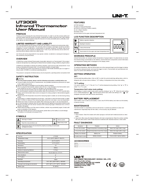
UT300Rlnfrared Thermometer User ManualPREFACEThank you for purchasing the new infrared thermometer. In order to use this product safely and correctly, please read this manual thoroughly, especially the Safety Instructions part. After reading this manual, it is recommended to keep the manual at an easily accessible place, preferably close to the device, for future reference.LIMITED WARRANTY AND LIABILITYUni-Trend guarantees that the product is free from any defect in material and workmanship within one year from the purchase date. This warranty does not apply to damages caused by accident, negligence, misuse, modification, contamination or improper handling. The dealer shall not be entitled to give any other warranty on behalf of Uni-T rend. If you need warranty service within the warranty period, please contact your seller directly.Uni-Trend will not be responsible for any special, indirect, incidental or subsequent damage or loss caused by using this device.OVERVIEWTo use the product properly, please read the following instructions carefully before use: Dispose the device and accessories properly according to local wasteFEATURESLCD FUNCTION DESCRIPTION ACCESSORIESBattery ----------------------------- 1Manual ----------------------------- 1Device ------------------------------ 1SPECIFICATION FAULT DIAGNOSISUT300R Non-contact lnfrared Thermometer (hereinafter referred to as "thermometer"). T his product measures temperature by collecting the infrared thermal radiation energy emitted by target surface. UT300R has advantages of simple and sanitary operation, quick and accurate measurement. It can measure temperature precisely within 1s by aiming the detector at target object.It is not allowed to be used in the presence of a mixture of flammable anesthetic gas, air, oxygen or nitrous oxide. UT300R is a continuous operating device.This product is composed of infrared sensor, circuit components, operating buttons and plastic shell.White backlightOption of Celsius/FahrenheitDynamic monitoring of battery capacityLow voltage indicationDisplay screenSound alarm for the upper and lower temperature limitWORKING PRINCIPLElnfrared thermometer can measure surface temperature of opaque objects. Its optical device can sense the infrared energy concentrated on the detector, and the electronic components convert information into temperature reading which is displayed on the display screen.OPERATING METHODST o measure temperature, allow the thermometer aim at the measured target, push the trigger to display the real time measured result; and loose the trigger to hold it. Thermometer will automatically shut down if no action were detected out within 8s.SETTING OPERATIONSET:Cyclical switching setting status: Click on SET to enter the cyclical switching setting status, which is designed with a circular order as follows: °C/°F setting→ temperature limit value mute setting.°C/°F setting:It is used to display °C or °F. The unit °C or °F will be displayed during setting. Click “▲” or “▼” to select °C or °F in cycle.Temperature limit value mute setting:fBATTERY REPLACEMENTOpen battery cover to take out the battery. Load a new 9V 6F22 battery and make sure the battery is placed correctly.MAINTENANCEThe thermometer is a repeatedly-used accurate device, so please pay attention to clean and maintenance. Especially keep the lens clean, or the accuracy may be affected.Clean:1. Clean chassis: Clean the chassis with cotton sponge or soft cloth with medicinal alcohol or clean water.2. Clean lens: Blow away the slipped of f grains with clean compressed air. Wipe the surface carefully with wet cotton swab. Cotton swab should be moistened with medicinal alcohol or clean water.SymptomHI (on the screen)LO (on the screen)Battery icon flashesPossible blank screenProblemTarget temperature exceeding rangeTarget temperature lower than rangeBattery lowBattery drainedActionSelect the target within rangeSelect the target within rangeReplace batteryCheck and/or replace batteryTo ensure safety and accuracy of measurement, only qualified maintenance personnel can repair it with original components.Replace the battery immediately once the battery indicator appears.Prior to using the thermometer, please check the box. If any damage to the thermometer were found, please do not use it. Inspect for damage or any shortage of parts.Do not place the thermometer near the objects with high temperature for long period.It is recommended to operate the thermometer within the environment of 15°C~30°C and RH<85%. Please use the thermometer indoor and do not expose it to strong sunlight or intense electromagnetic interference.Please ensure the temperature around the measuring object is stable, do not test during strong airflow.Avoid testing in unstable temperature environment - wait 30min to allow the thermometer to stable. Wait 10~30min to measure if the measuring object came from very high or very low temperature. Please wait 10min to measure new objects after measuring very high or very low temperature.It is recommended to measure thrice for every object and the highest occurring data should be used. Please accurately aim the sensor window at the measuring target. Otherwise error or HI/LO indicator will appear.Please keep the battery out of the reach of children, children may accidentally ingest. Contact with doctor immediately if that happens.If the thermometer will not in use for long period, please take out the battery to avoid leakage.The battery is not allowed to be placed in fire.。
鱼跃红外线额温计说明书

非接触式红外额温计使用说明书请在使用前仔细阅读本说明书。
本产品使用环境温度是15℃到35℃, 最佳温度25℃。
请不要把该产品靠近带电的物体,以免电击。
请不要在相对湿度大于85%的环境下使用该产品。
请不要将本产品太靠近电磁范围(如无线电,手机等)请不要将本产品靠近太阳下暴晒或靠近火源,更不能接触到水。
请不要撞击或掉落本产品, 若有损坏请不要使用。
额头上的头发,有汗,帽子或围巾会影响测量数据准确度。
请确认测量距离在1cm-5cm 范围。
为了得到准确而稳定的测量数据,请当室温变化很大的时候,应把本测量仪置于室内30分钟后 使用。
需要清洁时,请用酒精轻试仪器表面。
一旦产品出现问题, 请联系分销商,不要试图自行修理。
非接触式红外额温计由红外温度传感器、显示屏、电路板(含供电电路、测量电路和功外壳组成。
能按钮)、产品外观描述预期用途: 适用人群: 大于5岁的儿童和成人。
(儿童若无法操作额温计,建议由成人代为测量体温)。
通过测量额头的热辐射来显示被测对象(5岁以上人群)的体温。
测量部位炎症、外伤、术后等局部病变。
(使用前请仔细阅读)红外接收窗口扳机LCD显示设置按钮模式按钮选择按钮电池盖7.产品技术说明红外额温计通过被动红外线传感器探测到由人体释放出来的微弱的红外线能量,经过复杂的算法处理和各种补偿校正,可以准确的测得人体的体温。
8.产品技术参数32.0℃-45.0℃(89.6℉-113.0℉)±0.2℃/0.4℉ 35.0-42.0℃(95.0-107.6℉)±0.3℃/0.5℉ 32.0-34.9℃(89.6-94.8℉)±0.3℃/0.5℉ 42.1-45.0℃(107.8-113.0℉)℃或℉可转换0.1℃(0.1℉)液晶显示屏,3位半数字加特殊图标开机显示上一次测量记录的历史数据体温大于37.2℃(98.9℉)蜂鸣器BE……长鸣一声+两声BE…BE 报警提示约15秒无操作后自动关机2*1.5V AAA (锌锰电池)140.7mm X 89.7mm X 35.9mm98.7g临床重复性不超过0.3℃(0.5℉)0.08℃V1*注:参考体温计为江苏鱼跃医用仪器有限公司生产的型号为CRW-23标式腋下型)的玻璃体 温计,注册证号为苏械注准20152201431。