On the compositional properties of UML statechart diagrams
course2
南开大学软件学院
4
Abstraction
面向对象基本原则
Encapsulation
Object Orientation
南开大学软件学院 5
Modularity
Hierarchy
Abstraction: Manages Complexity
Salesperson Product Customer
Abstraction allows us to manage complexity by concentrating on the essential characteristics of an entity that distinguish it from all other kind of entities
Packages and subsystems support the definition of modular components.
Hierarchy
Asset
Levels of abstraction
Increasing abstraction
BankAccount
Security
RealEstate
Class and Object Name
Object Diagrams
An object diagram is most useful early in your development effort to model examples that support the investigation of requirements.
What is Polymorphism?
The ability to hide many different implementations behind a single interface
UML类图关系泛化、继承、实现、依赖、关联、聚合、组合

继承、实现、依赖、关联、聚合、组合的联系与区别分别介绍这几种关系:继承实现指的是一个class 类实现interface 接口(可以是多个)的功能;实现是类与接口之间最常 见的关系;在Java 中此类关系通过关键字implements 明确标识,在设计时一般没有争 议性;依赖可以简单的理解,就是一个类A 使用到了另一个类B ,而这种使用关系是具有偶然性的、、 临时性的、非常弱的,但是B 类的变化会影响到A ;比如某人要过河,需要借用一条船, 此时人与船之间的关系就是依赖;表现在代码层面,为类B 作为参数被类A 在某个method 方法中使用;Inte rfare指的是一个类(称为子类、子接口)继承另外的一个类(称为父类、父接口)的功能,并可 以增加它自己的新功能的能力,继承是类与类或者接口与接口之间最常见的关系;在Java 中此类关系通过关键字extends 明确标识,在设计时一般没有争议性;b lnterface_BQlass_A ClaSs_B关联他体现的是两个类、或者类与接口之间语义级别的一种强依赖关系,比如我和我的朋友;这 种关系比依赖更强、不存在依赖关系的偶然性、关系也不是临时性的,一般是长期性的,而 且双方的关系一般是平等的、关联可以是单向、双向的;表现在代码层面,为被关联类B 以类属性的形式出现在关联类A 中,也可能是关联类A 引用了一个类型为被关联类B 的全 局变量;聚合聚合是关联关系的一种特例,他体现的是整体与部分、拥有的关系,即has-a 的关系,此 时整体与部分之间是可分离的,他们可以具有各自的生命周期,部分可以属于多个整体对象, 也可以为多个整体对象共享;比如计算机与CPU 、公司与员工的关系等;表现在代码层面, 和关联关系是一致的,只能从语义级别来区分;组合组合也是关联关系的一种特例,他体现的是一种contains-a 的关系,这种关系比聚合更强, 也称为强聚合;他同样体现整体与部分间的关系,但此时整体与部分是不可分的,整体的生 命周期结束也就意味着部分的生命周期结束;比如你和你的大脑;表现在代码层面,和关联 关系是一致的,只能从语义级别来区分;对于继承、实现这两种关系没多少疑问,他们体现的是一种类与类、或者类与接口间的纵向 关系;其他的四者关系则体现的是类与类、或者类与接口间的引用、横向关系,是比较难区 分的,有很多事物间的关系要想准备定位是很难的,前面也提到,这几种关系都是语义级别Cl3ss A 十 depend<Qlass.B classBJ ;:;;VoidClass_B的,所以从代码层面并不能完全区分各种关系;但总的来说,后几种关系所表现的强弱程度依次为:组合>聚合>关联》依赖;聚合跟组合其实都属于关联只不过它们是两种特殊的关联因为本是同根生所以它们之间难 免会有相似之处下面让我们一起来看一下它们之间有何不同聚合与组合的概念相信不用我在此赘述大家就已经了解了下面直接上例子 程老师的《大话》里举大那个大雁的例子很贴切在此我就借用一下大雁喜欢热闹害怕孤独所 以它们一直过着群居的生活这样就有了雁群每一只大雁都有自己的雁群每个雁群都有好多 大雁大雁与雁群的这种关系就可以称之为聚合另外每只大雁都有两只翅膀大雁与雁翅的关 系就叫做组合有此可见聚合的关系明显没有组合紧密大雁不会因为它们的群主将雁群解散 而无法生存而雁翅就无法脱离大雁而单独生存一一组合关系的类具有相同的生命周期聚合关系图:构造函数不同雁群类:[csharp] view plaincopypublic class GooseGroup { public Goose goose; public GooseGroup(Goose goose) { this .goose = goose;} 10. }[csharp] view plaincopy1. 2. 3.4.5. 6.7. 8.9. 组合关系图:从从代码上看这两种关系的区别在于:1.public class GooseGroup2.{3.public Goose goose;4.5.6.public GooseGroup(Goose goose)7.{8.this.goose = goose;9.}10.}大雁类:[csharp] view plaincopy1.public class Goose2.{3.public Wings wings;4.5.public Goose()6.{7.wings=new Wings();8.}9.}[csharp] view plaincopy1.public class Goose2.{3.public Wings wings;4.5.public Goose()6.{7.wings=new Wings();8.}9.}聚合关系的类里含有另一个类作为参数雁群类(GooseGroup)的构造函数中要用到大雁(Goose)作为参数把值传进来大雁类(Goose)可以脱离雁群类而独立存在组合关系的类里含有另一个类的实例化大雁类(Goose)在实例化之前一定要先实例化翅膀类(Wings)两个类紧密耦合在一起它们有相同的生命周期翅膀类(Wings)不可以脱离大雁类(Goose)而独立存在信息的封装性不同在聚合关系中,客户端可以同时了解雁群类和大雁类,因为他们都是独立的而在组合关系中,客户端只认识大雁类,根本就不知道翅膀类的存在,因为翅膀类被严密的封装在大雁类中。
On Generalization and Overriding in UML 2.0
On Generalization and Overriding in UML2.0Fabian B¨u ttner and Martin GogollaUniversity of Bremen,Computer Science Department,Database Systems Group Abstract.In the upcoming Unified Modeling Language specifica-tion(UML2.0),subclassing(i.e.,generalization between classes)has amuch more precise meaning with respect to overriding than it had in ear-lier UML versions.Although it is not expressed explicitly,UML2.0has acovariant overriding rule for methods,attributes,and associations.In thispaper,wefirst precisely explain how overriding is defined in UML2.0.We relate the UML approach to the way types are formalized in pro-gramming languages and we discuss which consequences arise when im-plementing UML models in programming languages.Second,weaknessesof the UML2.0metamodel and the textual explanations are addressedand solutions,which could be incorporated with minor efforts are pro-posed.Despite of these weaknesses we generally agree with the UML2.0way of overriding and provide supporting arguments for it.1IntroductionThe Unified Modeling Language(UML)[OMG03b,OMG04]is a de-facto stan-dard for modeling and documenting software systems.Generalization in class diagrams(i.e.,subclassing)is one of the key concepts in the object-oriented methodology and in UML:It allows us to express that one class is a specializa-tion of another one.The more special class is described as a set of changes and extensions to the more general class.However,the concrete interpretation of subclassing in an executable envi-ronment was rather undefined with respect to overriding(see[Beu02,Pon02]) in previous UML versions(namely,1.x).In UML2.0,along many other major changes,generalization is defined much more precisely than in1.x.Although it is never mentioned explicitly on640pages,UML2.0introduces a covariant overriding rule for operations and properties.Hence,a subclass over-riding a superclass operation may replace the parameter types by subtypes of them.The same rule applies for attributes(the attribute type can be replaced by a subtype)and associations(the association end types can be replaced by subtypes),which can be redefined in UML2.0as well.The UML2.0provides a meaning for specialization which is consistent across operations,attributes,and associations.There has been a never ending discussion about whether covariance is a good meaning for overriding in the areas of programming languages and type theory. There has been nofinal agreement,but a general conclusion was that subclassing in the presence of covariant overriding cannot be used to define subtyping(fora formal explanation see[AC96],a good overview can be found in[Bru96]). Thus on the one hand,statically type checked programming languages cannot have a sound type system when covariant subclassing is generally allowed.On the other hand,it is argued that many situations in the real world are better modeled covariantly,a good argument for this is made,for example in[Duc02].A more formal comparison of both concepts which does not advocate either of them can be found in[Cas95].Commonly,UML models arefinally implemented in a statically typed pro-gramming languages such as Java,C++,and C#.Most of these programming languages do not permit covariant method overriding for the aforementioned type safety reasons(Eiffel[Mey88]is one of the few exceptions).Hence,there is a gap between subclassing semantics in UML and common OO programming languages,which must be considered during implementation of UML models. Nevertheless,we support the UML2.0view of subclassing as we think that the richer expressiveness outweighs the typing problems.This paper precisely explains how overriding is defined in UML2.0.We relate the UML approach to the way types are formalized in programming languages and we discuss which consequences arise when implementing UML models in programming languages.Despite of the mentioned typing problems we generally agree with the UML2.0way of overriding and provide supporting arguments.However,we have some concerns regarding overriding and subclassing in the final adopted UML2.0specification,which could be corrected with minor ef-forts:(i)There are two inconsistencies in the metamodel parts which deal with redefinition and subclassing.(ii)The definition of subclassing in UML2.0is scat-tered over a large number of class diagrams,several textual semantics sections, and a couple of additional interdependent OCL operations.Thus understanding how subclassing works in UML is a complex task.Since subclassing is such an important concept in object-oriented analysis and design,an explaining section is definitely missing in order to carry the meaning of UML subclassing to the broader audience.This is especially important in the context of Model Driven Architecture[KWB03,OMG02].(iii)Different from earlier versions,UML2.0 uses the term‘subtyping’at various locations where‘subclassing’is intended. Because of the mentioned covariant overriding rule in subclassing,the term‘sub-typing’should be used more carefully in the specification.This paper is structured as follows:Section2explains our notions of class, type,subtyping,variance,and subclassing used in this paper and relates sub-classing to subtyping.Section3shows how subclassing and overriding is han-dled in UML2.0.Section3also illustrates the consequences of having covariant overriding when implementing object models in statically typed programming languages.In Section4,we justify the existence of a covariant overriding rule in UML and address the mentioned concerns with regard to the technical realiza-tion in the specification.We close the paper with a conclusion in Section5.2BackgroundIn this section we shortly explain our notions for type,subsumption(subtype polymorphism),covariance,and contravariance,following[CW85,AC96].We re-late the notions of subclassing and subtyping.The section is designed to summa-rize central relevant notions in programming languages and type theory employ-ing minimal formalization overhead.Readers familiar with these notions may skip this section.2.1Type,Subsumption,and VarianceIn a programming language,a type represents a set of values and the operations that are applicable to them.For example the type Integer may denote the set of natural numbers N and the operations1,+,and−.In object-oriented pro-gramming,an object type represents a set of objects and the messages that can be sent to the objects.Types can be used to form a membership predicate over expressions:If an expression e evaluates to a result of type T we say e has type T, denoted as e:T.A strongly typed programming language provides mechanisms to ensure that only appropriate operations are applied to values.For example, "Hello"-5would be rejected,because a String type typically does not include a’-’operation for strings and numbers.In statically typed programming lan-guages like C++,Pascal,Java,C#and many others,expressions are assigned static types by a type checker before actual execution.The type checker guar-antees that if an expression has the static type T,its evaluation at runtime will always be a value of type T.A powerful typing rule which is implemented in nearly all common program-ming languages and in modeling languages like UML is the subsumption rule, also known as subtype polymorphism.The subsumption rule states that if an expression e has type S and S is a subtype of a type T,denoted as S<:T, then e has also type T.if e:S and S<:T then e:TAs a consequence,expressions may have more than one type.In order to have a sound type system(i.e.,no wrong types can be derived for expressions),only certain types can be related by the subtype relation<:.Typically,subtyping for complex types(i.e.,for function types and object types)is derived from simpler types(e.g.,for function types,<:is derived from the parameter types and return types of a function).Several sound type systems exist,with varying rules for subtyping,including virtual types,higher-order type systems(generic types)and other more elaborated concepts.The following general considerations hold for these systems as well.For languages with functions,the→type constructor can be used to con-struct function types.For example,Integer→String denotes the type of a function from Integer to String.As explained in[CW85],for given function types X→Y and Z→W the subtype relation X→Y<:Z→W can be defined as follows: X→Y<:Z→W iffZ<:X and Y<:WFor example the function type Real→Integer is a subtype of the function type Integer→Real,assuming Integer<:Real.Because the argument types X and Z are related by<:in the opposite direction as X→Y and Z→W,this subtyping rule for function types is contravariant w.r.t.to the argument type,and covariant w.r.t.the return type.Strictly speaking,we must always specify to which part of a complex type we refer to when using the term variance.Formally,variance is defined as follows:Let T{−}denote a type T with some‘hole’(i.e.,a missing type expression in it).Let T{A}denote the type T when the hole isfilled with a type A.T{−}is:covariant if A<:B implies T{A}<:T{B}and contravariant if A<:B implies T{B}<:T{A}.However,some‘default’references for variance have been established in the literature,such as the parameter type for a function type,so the subtype rule for functions is generally known as the contravariance rule for functions.In object-oriented languages,the most important concept is sending a mes-sage to an object(i.e.,invoking an operation).Thus in a statically typed pro-gramming language,the type checker prevents that inappropriate messages are sent to objects.We denote an object type as follows:T=[l1:T1,...,l n:T n],where l i are the elements(labels)of T(i.e.,methods andfields).In the case of afield l i,which is actually a method without parameters,T i is simply another object type(or a basic type).In the case of a method l i,T i is a function type.For example,a simple Point type may be modeled as follows:Point=[x:Integer,y:Integer,distanceTo:Point→Integer] Obviously,an object type T for which T <:T holds must contain the labels l1,...,l n since an object of type T must understand all methods andfield access operations that an object of the supertype T understands.Furthermore, in general we cannot allow that the individual label types T1,...,T n change in T .Subtyping for object types is sound,if we require T i=T i for i=1..n: [l1:T 1,...,l n+m:T n+m]<:[l1:T1,...,l n:T n]if T i=T i,i=1..n Formal proofs for this can be found in[AC96].The basic idea is as follows: Let o be an object of type T .If we allowed T i<:T i for some i in the above subsumption rule for object types then we could derive o.l i:T i.Thus the type checker would accept an assignment o.l i:=x for a value x:T i.But this as-signment would be valid only if T i<:T i(contradiction).The other way round, if we allowed T i<:T i,a similar contradiction occurs for a selection operation x:T i:=o.l i.Hence,type systems having a general co-or contravariant subtyp-ing rule for object types cannot be sound.However,in class based languages,where all methods of an object are de-clared statically(at compile-time),the types for method labels may change in subtypes in a covariant way(both,the object type and the method label type become more special).Thus for S=[l:X→Y]and T=[l:Z→W],S is a subtype of T(S<:T) iffZ<:X and Y<:W and l cannot be updated.Although the type of thelabel l varies covariantly with the object type,this rule is commonly known as the contravariance rule for method overriding,because the parameter type varies contravariantly with respect to the object type.Also common in the literature is the(unsound)covariance rule for method overriding which also refers to the parameter types.2.2Classes and SubclassesClasses describe objects with same implementations[Mey97].A class serves as a generator for objects.It specifies which state(i.e.,which attributes)and which behavior(i.e.,which methods)objects generated by the class have.Subclassing is a technique for reusing object descriptions(classes).A new class(the subclass)is described as a set of changes to an existing one(the superclass).The partial order denotes if a class is a direct or indirect subclass of another class.There is no general agreement about the exact semantics of subclassing(see e.g.,[CHC90,PS92,Bru96]).Common definitions of subclassing in programming languages involve the following mechanisms to describe how a new class is de-rived from an existing one:(i)Inheritance,properties of the superclass become properties of the subclass(often,this is the default),(ii)Overriding,properties of the superclass are redefined in the subclass(in typical OO languages,over-riding is restricted to methods),(iii)Extension,new properties are added to the subclass.Classes can be used to define types(a class c defines a type type(c)).Then, the subclass relationship can be used to define subtyping.This is done in most common statically typed OO programming languages as follows:type(s)<:type(c)iffs cTo achieve this behavior,types must be extended and distinguished by names (i.e.,c=c implies type(c)=type(c )).Thus,two distinct classes can have completely identical definitions but do not create the same type.This is known as name subtyping in the literature and is used,for example,in Java,C++,and C#.Other languages allow distinct classes to create the same type.However, having name subtyping or not has no impact on the variance aspects of overriding when subclassing is subtyping.While defining subtyping as subclassing has no consequences for inheritance and extension,it restricts the way overriding can be applied in subclassing. Especially,as explained above,method overriding cannot be covariant(i.e.,the parameter types of an overriding method cannot be subtypes of the parameter types of the overridden method)as explained above.After having discussed programming languages let us now turn to modeling languages.3How UML Handles Subclassing and OverridingIn this section,we explain how subclassing and overriding is handled in the UML 2.0metamodel using a simple example.We focus on overriding of methods,although the same principles apply to attributes and associations ends.3.1The Animals ExampleFig.1shows an example of a class diagram containing a generalization relation-ship.The class Animal generalizes the classes Cow and Rat.Read the other way,we say Cow and Rat are specializations or simply subclasses of Animal.Rat beep()CowAnimaleat(food)eat(food)makeMilk()Fig.1.Example class diagramAs said above,along with generalization comes inheritance and overriding.The eat(food)operation defined in Animal is inherited by Rat.Thus,instances of class Rat do not only have the operation beep(),but also eat(food).In class Cow,we have repeatedly defined eat(food)to indicate that the class provides a new definition of the eat(food)operation.In this case,we say Cow overrides,or,in UML 2.0terms,redefines eat(food)from Animal.Rat beep()FoodGrassCowAnimalmakeMilk()eat(food : Food)eat(food : Grass)Fig.2.Example class diagram with parameter typesHowever,the reader may notice that we have omitted the parameter types in Fig.1.If we fully specified our operations,the class diagram may look as in Fig.2.We now have clarified the fact that Cows shall only eat a certain kind of food:Grass.But,is this still overriding?Earlier UML versions left the wayoperations(methods)override intentionally undefined:The way methods override each other is a semantic variation point.[OMG03b,p.2-74].The upcoming UML2.0specification[OMG04]is more precise:An operation may be redefined in a specialization of the featured clas-sifier.This redefinition may specialize the types of the formal parame-ters or return results,add new preconditions or postconditions,add new raised exceptions,or otherwise refine the specification of the operation.[OMG04,p.78]Thus,in UML2.0,Cow::eat(food:Grass)may override Animal::eat(food:Food) if Grass is a specialization(i.e.,a subclass)of Food.As we explained in Section2, this kind of overriding is covariant.The following subsection shows how this restriction is modeled in the UML2.0metamodel.3.2Relevant Excerpts of the UML2.0MetamodelThe metamodel elements relevant for generalization and redefinition are scat-tered overfive class diagrams in the specification.Furthermore,constraints and additional operations are defined separately in the textual part.Thus,the de-scription is distributed over more than20(!)locations.The class diagrams in Figs.3and4combine all relevant aspects.Constraints and additional opera-tions are attached either in-place or as comments.We have given names to the invariants(which do not occur in the UML2.0specification)in order to refer to them in the following.Three invariant constraints occur in Figs.3and4.Two of them,RedefinitionContextValid and RedefinedElementsConsistent,belong to the metaclass RedefinableElement.The third,SpecializeValidType,belongs to the metaclass Classifier.Wefirst look at RedefinitionContextValid.This constraint is straightforward. Its meaning is,that for an element e which redefines another element e,e must belong to some subclass of the class in which e is defined.The additional operation isRedefinitionContextValid(e:RedefinableElement)must yield true for each redefined element.The second constraint,RedefinedElementsConsistent,is more subtle and has a lot of impact on the UML2.0semantics:Its meaning is that all redefined ele-ments must be consistent with the redefining element.The concrete meaning of ‘is consistent’is deferred to subclasses of RedefinableElement,e.g.,to Operation. To illustrate this constraint,we consider our animals example from Fig.2.On the metamodel level,it looks like the object diagram in Fig.5(we have omitted the operation makeMilk()and the class Rat for simplicity).isRedefinitionContextValid(r:RedefinableElement) =redefinitionContext−>exists( c1 |r.redefinitionContext−>exists( c | c.allParents−>includes(c1)))/redefinedElement {union}RedefinableElement isConsistentWith(e:RedefinableElement) = falseisRedefinitionContextValid(r:RedefinableElement)=...TypeconformsTo(o:Type)=false Class ClassifierinheritableMembers(c:Classifier)=member−>select(m|c.hasVisOf(m))general specific 11/redefinitionContext {union}redefinedElement−>forAll(e | isRedefinitionContextValid(e))inv RedefinitionContextValid [1]:redefinedElement−>forAll(e | e.isConsistentWith(self))inv RedefinedElementsConsistent [2]:parents−>forAll(c | maySpecializeType(c))inv SpecializeValidType [3]:conformsTo(o:Classfier)=(self=o) or allParents()−>includes(o)inherit(inhs:Set(NamedElement)=inhsmaySpecializeType(c:Classifier)=oclIsKindOf(c.oclType)Generalization isSubstitutable:BooleanFig.3.Condensed UML 2.0Facts about Generalization and Redefinition -Part AFig.4.Condensed UML 2.0Facts about Generalization and Redefinition -Part BformalParameter formalParameter type typegeneralspecificfeature feature redefinedElement general specific food :Parameter food’:Parameter :Generalization Grass :ClassFood :Class eat’:Operation Cow :Class :GeneralizationAnimal :Classeat :Operation Fig.5.Example as metamodel object diagramFor this object diagram,the invariant RedefinedElementsConsistent can be written out as follows:eat .redefinedElement →forAll(e |e .isConsistentWith(eat ))=eat .isConsistentWith(eat )=eat .formalParameter[1].type .conformsTo(eat .formalParameter[1])=food .type .conformsTo(food .type)=Grass .conformsTo(Food)=(Grass =Food)or Grass .allParents →includes(Food)RedefinedElementsConsistent is responsible for the mentioned covariant overrid-ing rule in UML 2.0.If one operation redefines (i.e.,overrides)another,all formal argument and return types of the redefining operation must be specializations of the formal argument and return types of the redefined operation.Finally,the third invariant SpecializeValidType intends that a classifier may specialize each of its superclasses.We show in Section 4that the operation maySpecializeType(c:Classifier)involved in the constraint depends on the OCL definition of subtyping in an ill-defined way.3.3Interpretation of UML Models using Covariant OverridingLet us consider again our animals class diagram from Fig.2.The following piece of program (pseudo code)illustrates the problem which arises when eat is covariantly overridden in class Cow.declare x :Animaldeclare y :Foodx :=someAnimaly :=someFoodx .eat(y)If we assume that instances of type Cow can be substituted for instances of type Animal (i.e.,by subsumption),then the expression someAnimal may evaluate to an object of type Cow and the result of someAnimal can be still safely assigned to the variable x .Further,x.eat (y )would be statically type safe,because the static type of x is Animal.Nevertheless,if the expression someFood evaluates to an instance which has type Food (i.e.,which has not type Grass),theevaluation of x.eat (y )will produce an error because Cow::eat is not defined for the parameter type Food.This consideration exemplifies why subclassing cannot be subtyping when the parameter types of a method are covariantly redefined,for the reasons given in Section 2.However,class based programming languages like Java,C++,or C#have (more or less)sound type systems and prohibit covariant method overriding.Actually,they only support invariant overriding,although covariant overrid-ing would be sound for methods (i.e.,parameter types could vary contravari-antly and return types could vary covariantly w.r.t.the object type).Newer versions of C++and Java allow at least covariant redefinition of return types[Str97][BCK +01].If a class diagram containing covariant overriding is to be translated into such a programming language,the inherent typing problem be-comes obvious.A pragmatic solution may look like the one in Fig.6.Rat beep()CowAnimalmakeMilk()eat(food : Food)eat(food : Grass)Rat beep()Cow Animal makeMilk()eat(food : Food)eat(food : Food)if (not food.oclIsKindOf(Grass))raise type errorelseeat food.oclAsType(Grass)Fig.6.Transformation to invariant overridingAlthough the animals example is now statically type safe,it still produces an error if cows shall eat food which is not grass.We have only deferred the error from compile time to runtime.It is important to see that this (potential)error is inherent to the UML class diagram and not a consequence of the implementation.The designer of the class diagram expresses that cows must not eat inappropriate food,for example to avoid mad cow diseases.Multi-methods [ADL91,BC97,CL95,DCG95]provide an alternative interpre-tation of covariant specialization.Instead of simply failing a dispatch (i.e.,a method call),one of the overridden base class methods may be called instead.Actually,a multi-method based semantics could have been chosen for overriding in UML 2.0.However,we feel that multi-methods are a less intuitive meaning for specialization than ‘simple’overriding.Furthermore,multi-method seman-tics are difficult to realize in common OO languages and,in general,can lead to ambiguities in the context of multiple inheritance.At least one commonly known OO programming language exists,in which covariant overriding as it is realized in UML2.0is directly available:Eiffel [Mey88,Mey97].Eiffel,aware of the mentioned typing problems,supports covari-ant overriding as a fundamental design aspect and thus is close to the UML2.0 understanding of subclassing.Our animals example could be directly imple-mented in Eiffel.A runtime error would be raised by Eiffel when a cow tries to eat food which is not grass.Although Eiffel is not statically type safe,ongoing work proposes that many runtime type errors could be eliminated by compilers by using more elaborated analysis and type-checking techniques[HBM+03].4Concerns with the UML2.0SpecificationDespite the subclassing resp.subtyping problem explained in the last section, we generally agree with the UML2.0way of defining redefinition for operations, attributes,and associations.Why do we agree?Even sound statical type systems such as in Java,cannot guarantee real substitutability for subtypes.A more special object may violate semantic contracts(e.g.,invariants)which a more general object fulfills.Type systems guaranteeing real substitutability would require a behavioral notion of subtyping(e.g.,the‘Liskov Substitution Principle’[LW94]).However,it seems that very few real world examples[Duc02]exist where objects of one class are generally substitutable for objects of another class.If subclassing must be subtyping when modeling real world aspects,very few subclassing relations can exist.On the other hand,it is a basic desire of designers to model set inclusion by subclassing(i.e.,the set of cows is a subset of the set of animals).Hence,although identifying subclassing and subtyping is desirable for programming languages to achieve reasonable statical safe type checking,it is not adequate for intuitive object-oriented modeling on a higher level of abstraction.Therefore,we agree with the covariant way of overriding in UML2.0.Nevertheless,we have a couple of concerns with the upcoming specification, which are not fundamental but regard the technical realization of how subclass-ing and overriding(redefinition)is described.4.1Concerns with the MetamodelWe have found two errors in the metamodel parts that model subclassing and overriding.These errors can befixed with minor efforts.Ill-defined operation Classifier::maySpecializeType Consider the third invariant constraint of the metaclass Classifier(named SpecializeValidType in Fig.3).For each instance c of Classifier,c.parents→forAll(c |c.maySpecializeType(c ))must hold.This can be rewritten using the definition of maySpecializeType toc.parents→forAll(c |c.oclIsKindOf(c .oclType))The built-in OCL operation o.oclIsKindOf(t)is defined as follows:‘The oclIsKindOf property determines whether t is either the direct type or one of the supertypes of an object’[OMG03a].Since subtyping in OCL requires sub-classing,the definition of maySpecializeType is circular:c may subclass c only if c is a subtype of c and if c is a subtype of c then c must be a subclass of c .Hence,maySpecializeType is not well-defined.As a proposal for solving this problems we argue for simply omitting Special-izeValidType from the UML 2.0specification,as it does not make any further restrictions to UML models.Operation Property::isConsistentWith contradicts textual semantics Another inconsistency can be found in Property::isConsistentWith .Consider the example in Fig.7.It is similar to the previous one,except that animals and cows now have a ‘food’attribute (i.e.,a property)instead of an ‘eat’operation.The (textual)specification states,in the covariant specialization manner,that an attribute type must be redefined by the same or a more specific type.However,if we write out the operation isConsistentWith we obtainfood .redefinedElement →forAll(e |e .isConsistentWith(food ))=food .isConsistentWith(food )=food .type .conformsTo(food .type)=Food .conformsTo(Grass)=(Food =Grass)or Food .allParents →includes(Grass)which obviously yields false.If we used this definition of maySpecializeType for Property,we gained a contravariant overriding rule for properties,which is not intended according to the explaining text and which does not match the general idea behind redefinition in UML 2.0.Apparently,the subterm type .conformsTo(p .type)must be flipped (i.e.,be rewritten to p .type .conformsTo(self .type))to achieve the intended covariant overriding rule for properties.Animalfood : Food general specific type typegeneralspecific feature feature redefinedElement food : Grass Cow:Generalization Food :Class Grass :Class:Generalizationfood :Property food’:Property Animal :Class Cow :Class Fig.7.Example with Properties。
On the Description of Communications Between Software Components with UML
On the Description of Communications Between SoftwareComponents with UMLZhiwei An Dennis PetersFaculty of Engineering and Applied ScienceMemorial University of NewfoundlandSt.John’s NL A1B3X5zhiwei@engr.mun.ca dpeters@engr.mun.caNovember12,2003AbstractFor the purpose of analysis and verification,in software design,architecture of the software system and communications between software components should be specified.Unified Modeling Language(UML)isa standard software design notation that includes Sequence diagrams and Collaboration diagrams,whichdescribe the interaction between objects.They also can be used to describe communications betweencomponents.In this paper,we discuss what should be modeled in the communication and how theelements in UML can be adopted to model the communication.A formalism of UML design models thatcan be used for design analysis is also proposed.1IntroductionSoftware systems are often composed of several components each of which is a computational entity that realizes a particular ponents interact with each other by communications between them. Documenting communications is one part of software design and the design models should be verifiable to ensure the correctness of the design.In software systems,synchronous and asynchronous communication could exist.To describe different types of communications between components,several methodologies have been proposed.Two kinds of methods are1)Architectural Description Languages(ADL)[1]and2)UML in architecture description [3,4].The Unified Modeling Language(UML)[6]is a standard modeling language with rich diagrams to model static and dynamic aspects of a system.Sequence diagrams and collaboration diagrams are two types of UML diagrams widely used in communication description.In a sequence diagram,the horizontal dimension represents different objects and the vertical dimension represents time.Each object has a lifeline with activation bars.The bar begins with the invocation of a method and stops when the method ends.Arrows represent messages transmitted between the objects.The life line could have a branch at a time point and the two or more lines could merge at a later time.The branch means conditional branch or concurrency.Sequence diagrams specify time explicitly.In a sequence diagram,objects interact with each other via messages.A message may specify several different time points such as sending time and receiving time.One message links two events and the order of events is specified.A collaboration diagram presents a set of roles to be played by instances as well as required relationships between them.It also presents a set of messages specifying the interaction between the instances playing the roles to achieve the desired result.In collaboration diagrams,message order is described by adding numbers to arrow labels.To verify the UML design models,the idea of model checking[2]is proposed.Typically,a model checking algorithm checks properties of a system description based on a(finite)state machine model with parallel composition.To generate the automata based model,sequence diagrams should be analyzed and translated into state machines.A sequence diagram describes time explicitly so the timing relation of the events can be derived from it.In UML design models for a software system there are usually several sequence diagrams.Analysis of all of these diagrams could generate a state machine based model for model checking.The rest of this paper is organized as follows:In Section2,we discuss types of communications between software components and what should be modeled in the communication.Section3uses an simplified elevator example to show how to use UML diagrams to describe interactions.In Section4,we propose one behavior model of the software system and illustrate how information in Sequence diagrams could be mapped to the behavior model.In Section5,we draw some conclusions.2Types of CommunicationsCommunications between software components are either asynchronous or synchronous.The difference be-tween these two classes of communications is that synchronous communications involves blocking operations in the communication.In synchronous communication,the component is suspended after the send operation until it is unblocked by the other partner in the communication.In asynchronous communication,nonblock-ing operations are used which means that the components will proceed without waiting for the completion of the communication.The following classes of communications are possible.Shared Variable A variable that can be accessed by more than one component is a means of communi-cation.The basic operations on a shared variable are read and write so mutual exclusion is the main problem in this type.Asynchronous Message Passing(AMP)In this type of communication,there are two events1)the sender sends out the message and continues running,2)the receiver receives the message.If the receiver is available and the processes are co-located,1and2happen at essentially the same time and could be considered as the same event.If the receiver is not available,the message is stored in a buffer until the receiver is available.The sender is not blocked at any time.Synchronous Message Passing(SMP)In Synchronous Message Passing,the sender cannot send the message until the receiver is available to receive it.There is no buffer in this type of communication. Procedure Call In Procedure Call,there are four events1)the caller calls an access program in the callee,2)the access program is invoked,3)the access programfinishes,and4)the caller knows that the calleefinishes.In Procedure Call1and2happen at the same time and they could be considered as one event.3and4are also the same event.Between the events of2and3,the caller is blocked. Remote Procedure Call When there are more than one process and a process calls a function in another process,this type of communication is called Remote Procedure Call(RPC).The mechanism of RPC is almost the same as procedure call except that the function in another process may be unavailable because that function is called by another component and it can not be called twice at the same time.Asynchronous communication and synchronous communication have the similar semantics and can be modeled in a similar way.For example,synchronous message passing is a special case of asynchronous message passing without a buffer and asynchronous message passing between two components could be modeled as two synchronous messages:from one component to a buffer and then from the buffer to the other component.Table1:Concepts in Communication and UMLCommunication Concepts UML NotationsComponent ObjectComponent’s Life LifelineRunning Access Program Activation BarMessages or Calls Message Arrow(Operations)Message Name or Call Name Arrow LabelEvent Two Ends of an ArrowTwo ends of an Activation Bar3Description of Communications in UMLThe techniques for denoting communication types in UML are defined in UML1.4.To describe communi-cations with UML,thefirst step is to map concepts in communication to the elements in UML diagram. Table1illustrates the relations of UML notations and concepts of communication in this work.Operations and events should be distinguished here:operations have time duration and they are often composed of several events which are points in time.Some concepts in communication cannot be represented by UML notations.For example,the data state is not in UML at all and control state may be represented implicitly.After mapping concepts of communications to elements of UML,we need to model communications with the semantics of collaboration diagrams and sequence diagrams.To describe the whole system,thefirst step is to use collaboration diagrams to describe relations between objects,the second step is to use sequence diagrams to describe interactions.3.1Collaboration Diagrams in CommunicationBecause a collaboration diagram presents a collection of instances and their relationships,we can use it to describe the relations between components,as illustrated in Figure1.The arrows between components represent messages and calls.Since this diagram only illustrates the static relations between components no number is used in the arrow label.Figure1:Elevator System in Collaboration Diagram3.2Sequence Diagrams in CommunicationA sequence diagrams describes several aspects of the communication.First,it can describe the phenomenon of when one access program is invoked,what other events could be generated during the run time of theaccess programs.Second,it can illustrate the mechanism of communication.When one access program is invoked,it may send messages to or call access programs in other components.Messages and calls are distinguished by different types of arrows.For example,Figure 2shows that when the access program schedule is invoked,three operations,getFloor ,getDirection and nextStop happen.Figure 3illustrates the order of the events in the case of AMP.Figure 2:Stimulus in UML,IFigure 3:Stimulus in UML,IISince there are a finite number of access programs in the system and we can draw one sequence diagram for each access program,the number of sequence diagrams is equal to the number of access programs and hence the number of sequence diagrams will not grow too rapidly as the system size increases.Figure 2and Figure 3only illustrate the behaviour when one access program is invoked.More sequence diagrams are needed to completely describe the communications between components,including conflict resolution.Figure 4illustrates all types of communications discussed in Section 2.In I,a procedure call is illustrated:component P calls an access program in component Q (operation a ).The access program in Q is invoked at the same time as the component P calls it and P is blocked.After the access program in Q ends,P is unblocked.In II,P calls Q (operation a )first and it is blocked until the operation b .If Q is unavailable and R wants to call Q,R is blocked and should wait until the operation b is over.R will be unblocked only after the operation d .In III,P sends a message (operation a )to Q and P is not blocked.If Q is not available before it finishes serving the message form P and R sends a message to it (operation b ),a buffer is used to store the message and re-send the message to Q (operation c )after Q is available.In this type of communication,no component is blocked.In IV,P sends a message to Q (operation a ),R sends a message to Q (operation b )when Q is not available and Ris blocked,this operation can finish only after Q finishes serving the message from P.When the operation b ends,R is unblocked and Q begins to serve the message from R.In V,read andwrite are two basic operations and they should obey the rules of mutual exclusion.I. Procedure Call II. Remote Procedure CallIV. Synchronous Message Passing P,Q,R are componentsa, b, c, d are messages or callsvar is shared variable Figure 4:Types of Communication in UMLFigure4only illustrates some basic types of communications.In a realistic system mixtures and variants of these communications exist.In Figure5,the communication are AMP.In this example,the coordinator can access two messages from two schedulers so we can draw two lifelines for coordinator.A buffer is necessary when message delete cannot be processed immediately after being sent.Figure5:Communication Mechanism4Analysis TechniqueTo verify UML design models,we need a formalism to accept all sequences of events described by the model. In software systems,components are modeled as state machines and most model checking algorithms accept automata based specification as the input,so parallel composition of state machines is the model in this research work.4.1From UML to State Machine ModelSequence diagrams describe the relative order of events.In communications,there are several possible orders of events so the events are not totally ordered.The best description of the relationship of events is a partial order .In[5],relations of messages in Message Sequence Charts(MSC)are translated into a partial order. Because sequence diagrams come from MSCs with extension,a similar process can be used to extract the partial order from sequence diagrams.UML Sequence diagrams do not have state variables in them so they do not represent component state precisely.UML Statecharts have the ability to describe the behavior of the component but Module Interface Specifications(MIS)[7]make better use of abstraction and are more amenable to machine processing.A discussion of the process for generating a formal behaviour model from component MIS is beyond the scope of this paper.From the discussion above,we can propose that the problem of synthesizing concurrent automata from Sequence diagrams can be divided into two steps.1)Describe partial order relation in sequence diagrams formally and2)synthesizing concurrent automata model from the partial order relations and component MIS. 5ConclusionUML interaction diagrams have the ability to describe the communication between software components. Collaboration diagrams describe the relations between components and sequence diagrams describe two aspects of the interaction:1)when one event happens,what other events could happen,and2)what communications mechanisms represent the communication types.To verify software design,an automata based behavior model could be derived from the sequence diagrams and used for model checking.References[1]Robert Allen and David Garlan.A formal basis for architectural connection.ACM Trans.Software Eng.and Methodology,July1997.[2]E.M.Clark,O.Grumberg,and D.Peled.Model Checking.MIT Press,2000.[3]Hassan Gomaa.Designing Concurrent,Distributed,and Real-Time Applications with UML.Addison-Wesley,2000.[4]Christine Hofmeister,Robert Nord,and Dilip Soni.Applied Software Architecture.Addison-Wesley,2000.[5]Madhavan Mukund,K.Narayan Kumar,and Milind Sohoni.Synthesizing distributedfinite-state systemsfrom MSCs.In Proc.Int’l Conf.Concurrency Theory(CONCUR),number1877in Lecture Notes in Computer Science,pages521–535,University Park,PA,2000.Springer-Verlag.[6]Rational Software Inc.,et al.OMG Unified Modelling Language Specification,version1.5edition,March2003.[7]Yabo Wang.Formal and abstract software module specifications—a survey.CRL Report238,Commu-nications Research Laboratory,Hamilton,Ontario,Canada,November1991.。
架构师之路-业务领域建模

架构师之路-业务领域建模领域模型的概念及作⽤领域模型是对领域内的概念类或现实世界中对象的可视化表⽰。
⼜称概念模型、领域对象模型、分析对象模型。
它专注于分析问题领域本⾝,发掘重要的业务领域概念,并建⽴业务领域概念之间的关系。
概念⽐较深奥,其实说⽩了就是我们把基于对业务的理解画成⼀个类图,并画出这些类之间的关系(⾯向对象)。
领域模型可以整理业务中的概念以及关系,帮助团队中的成员对业务的理解保持⼀致,往后可以指导数据库设计、系统功能设计、指导开发。
在整个系统建设周期能起到 上接需求,下承开发 的作⽤。
那既然领域模型如此重要,我们是不是要在类图中尽可能的展⽰对象的属性和⽅法,以便更好的指导后续的开发设计。
恰恰相反,我们在建模的时候不要将注意⼒集中在属性或⾏为上,应该摆脱这些细枝末节,抓住领域对象定义的最基本特征,只需要体现对象模型的重要概念。
如果细节过多很容易产⽣ ”只见树⽊,不见森林“ 的现象。
下⾯我们看⼀个简化后的报销业务的领域模型,加深⼀下印象。
完成⼀个领域模型建模,主要需要做两件事:1. 定义类的关键属性和关键⾏为;2. 定义类与类之间的关联关系。
定义类的属性和⾏为定义类的属性和⾏为⽐较简单,⽤设计⼯具拖⼀个class即可,这⾥只需要注意⼀下属性和⾏为的访问权限。
- 表⽰private# 表⽰protected~ 表⽰default,也就是包权限+ 表⽰public定义类与类之间的交互关系在UML类图中,定义了六种类之间的关系,他们分别是: 泛化(Generalization), 实现(Realization),关联(Association),聚合(Aggregation),组合(Composition),依赖(Dependency)。
关系⽐较多,⽽且有些还⽐较相近,⽐如聚合和组合,接下来我们逐渐讲解:泛化(Generalization)介绍:泛化(Generalization)表⽰类与类之间的继承关系,接⼝与接⼝之间的继承关系。
UML试题库

选择题在面向对象系统中,用(15)关系表示一个较大的“整体”类包含一个或多个较小的“部分”类。
(15)A. 泛化 B. 聚合 C. 概化 D. 合成RUP(Rational Unified Process)分为4个阶段,每个阶段结束时都有重要的里程碑,其中生命周期架构是在(18)结束时的里程碑。
(18)A. 初启阶段B. 精化阶段C. 构建阶段D. 移交阶段UP(统一过程)是用例驱动的、以架构为核心、迭代和增量的软件过程框架,它提供了一种(32)的特性。
(32)A. 演进 B. 敏捷 C. 测试驱动 D. 持续集成●●面向对象分析与设计中的(37)是指一个模块在扩展性方面应该是开放的,而在更改性方面应该是封闭的;而(38)是指子类应当可以替换父类并出现在父类能够出现的任何地方。
(37)A. 开闭原则B. 替换原则 C. 依赖原则 D. 单一职责原则(38)A. 开闭原则B. 替换原则 C. 依赖原则 D. 单一职责原则● 在选择某种面向对象语言进行软件开发时,不需要着重考虑的因素是,该语言(39)。
(39)A. 将来是否能够占据市场主导地位B. 类库是否丰富C. 开发环境是否成熟D. 是否支持全局变量和全局函数的定义● (40)限制了创建类的实例数量,而(41)将一个类的接口转换成客户希望的另外一个接口,使得原本由于接口不兼容而不能一起工作的那些类可以一起工作。
(40)A. 命令模式(Command) B. 适配器模式(Adapter) C. 策略模式(Strategy) D. 单例模式(Singleton)(41)A. 命令模式(Command) B. 适配器模式(Adapter) C. 策略模式(Strategy) D. 单例模式(Singleton)● (42)是指在运行时把过程调用和响应调用所需要执行的代码加以结合。
(42)A. 绑定 B. 静态绑定 C. 动态绑定 D. 继承● (43)设计模式允许一个对象在其内部状态改变时改变它的行为。
Derivation of System Integration Tests from Design Models in UML
Derivation of System Integration Tests fromDesign Models in UMLOliver Alt 1and Markus Schmidt 21Robert-Bosch GmbH,CM-DI/ESI2Daimlerstr.6D-71226Leonberg,Germanyoliver.alt2@2Real-Time Systems LabDarmstadt University of TechnologyD-64283Darmstadt,Germanymarkus.schmidt@es.tu-darmstadt.deAbstract.As model-driven software development is increasingly used,techniques to derive additional information from design models are rapid-ly explored.One kind of these additional information is test information.In this paper we present an approach of deriving a certain kind of testinformation for system integration test from a given design model.Fora given domain with a generic behavioral model our approach has theability to generate system integration tests that are specific for any designmodel of the same domain.The system integration tests are generatedas sequence diagrams,where every diagram represents one specific testcase for a concrete design model.The approach is of general use sinceall models are UML 2models.We illustrate our approach using a casestudy for a simplified MOST audio system.Keywords:System Integration Test,UML 2,Profiles,MOST1IntroductionAs software systems became larger and more complex,some abstraction in formof models were used to cope with the complexity.Even these abstract descriptionbecame too complex to include information for all aspects of a system.Non-functional information (e.g.dependability or testing)are typically not part ofa system model.This is critical since testing is an important part of softwaredevelopment.Studies indicate that at least fifty percent of the overall costs ofsoftware development are devoted to testing [1].As it is nearly impossible to testa complex system completely,it would be a great benefit if some tests could begenerated from the system model itself.In the case of model-driven engineering(MDE)this means derivation of testing information from the developed system model.Work supported in part by the European Community’s Human Potential Programmeunder contract HPRN-CT-2002-00275,SegraVisSince it is nearly impossible to develop an approach that covers all modeling languages,we focus our approach on the widely used UML[2].Scenario-based techniques are frequently used in preliminary work on UML-based test synthesis. In[3]Pickin et.al.presented a method to generate system tests from test sce-narios and design models.They need two external tools(UMLAUT and TGV) for the whole synthesis.Another approach to derive integration tests was proposed by Hartmann et.al.[4].They use communicating statechart to describe the interaction between system components.The remainder of this paper is structured as follows.A simple MOST(Media Oriented System Transport)audio system that serves as our domain example is introduced in section2.In section3,we describe our approach to generate specific tests for integration test purposes.Generic behavioral models for MOST components are presented in section4.Section5exemplifies the derivation of test sequences for our domain example.Section6concludes the paper with a discussion of further directions.2DomainIn modern cars the multimedia functions like driver entertainment,navigation and telematics are realized as a distributed system of electronic control units (ECUs).In the domain of car multimedia the ECUs are often connected via the MOST network.The complete car multimedia system in modern cars con-sists of a dozen ECUs from different vendors with thousands of syntactically correct communication messages.To verify these complex systems new model-based development and testing techniques are developed and evaluated for the development process of OEMs and suppliers like Robert-Bosch.2.1MOSTMedia Oriented System Transport[5]is an object oriented network system, designed to transport multimedia data and control messages to control the con-nected devices.The device functions are organized as function blocks.A hardware MOST device can host one or more function blocks,e.g.a hardware device hosts function blocks for radio,CD player,amplifier,and navigation.But it is also possible to distribute these function blocks over many hardware devices.The DeviceID.FBlockID.InstanceID.FunctionID.OpType.Length(Data)Fig.1.Definition of the MOST control message formattransport medium for MOST is afiber optical cable and the topology is a ring. One device is the timing master,the other devices are slaves.The definition for a MOST message is given onfigure1.By using the specified operation types(OpType)like Set,Get,Start or StartResult a controlling device is able to modify or request the state of functions in a function block.With the exception of Set and Start all request messages are responded by an associated response message.The syntax definition for the messages is given in the so-called function catalog.Examples of these function catalogs are[6]and[7].2.2UML2Profile for MOST audio systemProfiles offer the possibility to adapt UML to a certain domain.The primary extension mechanism is the stereotype which is a limited kind of a metaclass.A simple part of the whole MOST specification is presented as a profile in figure2.This profile contains hardware and software constructs,where every MOST construct is mapped to a stereotype of the same name.Every stereotype extends the metaclass Classifier,since we will model these MOST constructs as different UML model elements(ponents or objects).The stereotypes form a hierarchy both for hardware and software components.Every hardware construct has a device identifier devID,where there exists a specific stereotypeFurthermore,the stereotype FunctionBlock contains attributes to specify the function block identifier(fbId)and the specific instance identifier(instId)of a certain MOST function block.As every MOST audio source has its own source number the associated stereotype contains the attribute srcNr to specify this number.A similar attribute sinkNr specifies the number of a audio sink.2.3An example MOST systemAn example of a MOST system with three source function blocks and one sink function block,distributed on two hardware devices is given onfigure3.We apply here the stereotype definitions from our MOST-specific profile.The components are the physical MOST hardware ECUs including instances of function blocks. The connections between the component ports model the physical connections via thefiber optical cable.In the device PlayerUnit we have two similar function blocks of type AudioDiskPlayer.Therefore,they need different instance ids. The controlling device is the system master and controls the two slave devices PlayerUnit and HifiAmplifier.Fig.3.Structure of example MOST system3ApproachWe chose UML2[2]as our modeling language since it is an open standard and has thirteen different diagram types for both structure and behavior.An important benefit is the built-in extension mechanism of UML-the profiles. This offers the possibility to tailor UML models to domain specific needs.In addition to this application we use profiles to map generic behavioral models toa concrete design model.3.1Derivation of test sequencesDeveloping domain specific models in UML is done using a specific profile. As it is shown infigure4the design model SpecificModel uses the profileformed into a set of sequence diagrams where each diagram represents a single test case.All sequence diagrams together represent specific system integration test sequences.4BehaviorTo describe the dynamic behavior of our system,especially the MOST function blocks,we can use the UML2behavioral diagrams such as statecharts,activity or sequence diagrams.In the domain of MOST typically Message Sequence Charts3 are used to specify and describe the system behavior[8].So we chose UML sequence diagrams to specify the MOST communication behavior.Table1gives an overview of the MOST functions used in our examples in the next sections.4.1Generic(MOST-)behaviorTo define the behavior in a generic way,we replace specific diagram information by wild-cards in square brackets([]),corresponding to our profile definitions. 3telecommunication standard(ITU-T Z.120),nearly identical with UML2sequence diagramsFunctionBlock Function.OpType Data MeaningAll FktIds.Get-Returns list of func-tion Ids for functionblock AudioSource Allocate.StartResult SrcNr Reserve audiochannel for sourceAudioSink Connect.StartResult ChannelList,SrcDelay,SinkNr Connect sink to au-dio channelAudioSource SourceActivity.StartResult SrcNr,Activity=On Activate audio sourceAudioDiskPlayer DeckStatus.Set Play Start playback AudioDiskPlayer DeckStatus.Set Stop Stop playbackTable1.MOST functions used in our exampleTo derive a concrete behavioral scenario we must just replace the generic notation by the concrete values,defined in the system design model.The generic sequence diagram to request the function Id list for a certain function block is given infigure5.A MOST master device may use this functions -available in all function blocks-to scan the network and get the available functions in the devices and their function blocks(plug and play functionality). Following the MOST specification we use the message notation introduced in figure1to model the communicationflow in the sequence diagram.You can see the application of our generic notation,where e.g. [FunctionBlock.instId]references the attribute instId of the stereotype FunctionBlock.Fig.5.Get function IDs as sequence diagram4.2Generic source-sink behaviorTo transmit audio data between source and a sink,the source atfirst has to allocate a channel on the MOST and then the sink can connect to this channel to receive the data.The generic behavior sequence for building such an audio connection is given infigure6.In the example sequence diagram we have interactions between two different function blocks and the controller.Sources and sinks are special function blocks and thus they are a refinement, corresponding to the generalization in our profile.In the sequence diagram we use therefore the wild-cards[AudioSource]and[AudioSink]as replacement of the specific MOST parameters.A more complex scenario is the change of the source with more than two involved function blocks(at least two sources and one sink).In such a case we add a numeric value to the generic identifiers(e.g.[AudioSource1]).For lack of space we can not present this example here.Fig.6.Generic behavior for building an audio connection between source and sink4.3Generic cd-player behaviorAs further refinement we define the generic behavior of special sources and sinks. Such a source for example may be an audio disc player with sequences defining the control messages to start and stop playback.The generic definition is done in a similar way as described for sources and sinks,but in this case we use wild-cards corresponding to our refinement of AudioSource and AudioSink in our profile(e.g.[AudioDiskPlayer]).Fig.7.Structure of behavioral packagesThe relation between our behavioral packages is given infigure7and reflects the hierarchy of common behavior of MOST function blocks from our example. Due to of space we have omitted a specific audio sink(e.g.amplifier).5Deriving test sequencesTo derive system test sequences we need additional behavioral information.We have to define the order of execution for our generic sequences.This could be done using UML interaction overview diagrams,similar to the use of activity diagrams described in[9].Fig.8.System behavior sequenceThe interaction sequence for our example system is given infigure8.To keep it simple we show only a part of the whole system description.With all these information we are now able to generate a permutation of sequences for our example system.From our system model and the profile defi-nition we get all necessary informations for replacing the generic wild-cards with the system specific data.A test sequence that is automatically generated from the activity diagram infigure8and the design model infigure3is shown infig-ure9.All generic information is replaced by specific information from the design model.Sequence diagrams are only one possible view of test sequences.To get an automated execution of the test sequences we can generate e.g.XML for the commercial CANoe.MOST tool from Vector Informatik[10]or TTCN-3[11] code and use the test-environment for MOST systems as described in[12]and [13]to execute the tests.Fig.9.Test sequence with PlayerUnit.CDPlayer and HifiAmplifier.Amplifier6Conclusions and OutlookIn this paper,we introduced an approach to automatically derive test informa-tion for any design model of a certain domain.Starting from a given domain with a generic behavioral model,our approach has the ability to generate spe-cific system integration tests for any design model.These integration tests are depicted as a set of sequence diagrams.Every sequence diagram represents a specific test case for a given design model.The description of a test case as a sequence diagram is an approved method.But instead of manually writing a new sequence diagram for any possible combination from the system model,we generate these concrete sequence diagrams.To be as general as possible,we chose UML2as our modeling language. Therefore,our approach can be used with any UML2compliant modeling tool. The approach uses the following groups of models.1.A profile containing stereotypes that specify certain elements of the domain.2.A behavioral model that describes the behavior of domain components in ageneric manner.3.A specific system model that uses the profile to specify system components.Models of thefirst two groups are specific for a certain domain(as in our ex-ample for a simplified MOST audio system)and can be reused for every concrete model of the third group.The fundamental basis of our approach is the extension mechanism of UML2-the profiles.These stereotypes are used as links between elements of a designmodel and elements of the generic behavioral model.Our approach can be used with every UML2compliant tool.Only one additional plug-in is necessary.We are currently implementing the described approach.As such we are work-ing on an implementation of the generator as a plug-in for the UML2tool Enterprise Architect[14].After the completion of this plug-in we will evalu-ate our approach with more realistic examples.As such we have to extend the MOST profile to include more MOST devices both in the design models and the behavioral models and to model extended test oracle information.Another research direction is the description of behavior with activity diagrams instead of sequence diagrams.Activity diagrams offer constructs to specify behavior in a more concise way(e.g.explicit modeling of objectflow),since it is possible to describe a more general behavior beyond plain communication. References1.Harrold,M.J.:Testing:a roadmap.In:ICSE’00:Proceedings of the Conferenceon The Future of Software Engineering,New York,NY,USA,ACM Press(2000) 2.OMG:UML2.1Superstructure Specification.OMG.(2006)http://www.omg.org/docs/ptc/06-01-02.pdf.3.Pickin,S.,Jard,C.,Traon,Y.L.,J´e ron,T.,J´e z´e quel,J.M.,Guennec,A.L.:Systemtest synthesis from uml models of distributed software.In:FORTE’02,London, UK,Springer-Verlag(2002)4.Hartmann,J.,Imoberdorf,C.,Meisinger,M.:Uml-based integration testing.In:ISSTA’00:Proceedings of the2000ACM SIGSOFT international symposium on Software testing and analysis,New York,NY,USA,ACM Press(2000)60–70 5.MOST Cooperation:MOST Specification Rev.2.308/2004.MOST Cooperation.Rev.2.3edn.(2004)6.MOST Cooperation:MOST FunctionBlock AudioDiskPlayer.MOST Cooperation.Rev.2.4edn.(2003)7.MOST Cooperation:MOST FunctionBlock Audioamplifier.MOST Cooperation.(2003)8.MOST Cooperation:MOST Dynamic Specification.MOST Cooperation.2.1edn.(2005)9.Briand,L.,Labiche,Y.,eds.:A UML-Based Approach to System Testing,SoftwareQuality Engineering Laboratory Carleton University,Carleton University(2002) 10.Vector Informatik:CANoe.MOST Version5.2-Simulation-and testtool for CANand MOST systems,www.vector-informatik.de(2005)11.ETSI:The Testing and Test Control Notation version3Part1:TTCN-3CoreLanguage.ETSI.Etsi es201873-1v2.2.1edn.(2003)12.Burton,S.,Baresel,A.,Schieferdecker,I.,eds.:Automated testing of automotivetelematics systems using TTCN-3,3rd Workshop on system testing and validation, Fraunhofer IRB Verlag(2004)13.Schmidt,M.,Herrmann,J.,Baresel,A.,eds.:Domain Specific Test Systems Au-tomotive Case Study Description,3rd release,TT-MEDAL Consortium(2005) 14.Sparx Systems Pty Ltd.:Enterprise Architect 6.0.(2006)http://www..。
uml 参考题(带答案版)
1、面向对象的核心要素:对象,封装,消息,类,抽象,继承,多态性(7个)2、封装把类构成那两个部分,又提供了哪两种保护两个部分:接口部分,和实现部分两种保护:1,对象内部的状态被保护起来,不会被与该对象沟通的对象直接篡改;2另一方面,对象内部特征的变化不会改变其他对象与该对象的沟通方式。
(另一种老师课件的答案:两种保护:1.首先保护对象,防止用户直接存取对象的内部细节;。
2.其次封装也保护了客户端,防止对象实现部分的变化可能产生的副作用,即实现部分的改变影响到客户端的改变。
)3、消息提供了服务的哪四个方面对象标识,服务(方法)标识,输入信息和回答信息等5、下面是一个用例描述的片断:Use Case: Withdraw Cash(提取现金)参与者:Customer主事件流:1. 储户插入ATM卡,并键入密码。
2. 储户按“Withdrawal”按钮,并键入取款数目。
3. 储户取走现金、ATM卡并拿走收据。
4. 储户离开。
上述描述中存在的问题:只描述了参与者的动作序列,没有描述系统的行为。
改进的描述:答:1. 通过读卡机,储户插入ATM卡。
2. ATM系统从卡上读取银行ID、帐号、加密密码、并用主银行系统验证银行ID和帐号。
3. 储户键入密码,ATM系统根据上面读出的卡上加密密码,对密码进行验证。
4. 储户按“FASTCASH”按钮,并键入取款数量,取款数量应该是5美元的倍数。
5. ATM系统通知主银行系统,传递储户帐号和取款数量,并接收返回的确认信息和储户帐户余额。
6. ATM系统输出现金,ATM卡和显示帐户余额的收据。
7. ATM系统记录事务到日志文件。
7、什么是场景,一个用例可以有多少个主要场景和次要场景?场景:是使用系统的一个特定情节或通过用例的一个特定执行路径。
每个用例有且只有一个主要场景可以有多个次要场景8、按照耦合度从高到低,说明类之间的关系有哪些?由强到弱:继承,组合,聚合,关联,依赖9、标准类图中成员四个可见性分别用什么表示?Public + Protected # Package ~Private -10、association aggregation generalization dependency 分别代表什么关系关联关系聚合关系泛化关系依赖关系11、给出下面带关联类类图的另一种普通类图表示。
UML附带答案
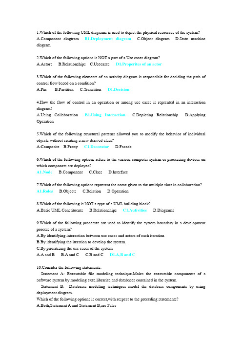
1.Which of the following UML diagrams is used to depict the physical resources of the system?ponent diagtram B1.Deployment diagram C.Objent diagram D.State machine diagram2.Which of the following options is NOT a part of a Use cases diagram?A.ActorsB.Relationshipsecases D1.Properites of an actor3.Which of the following elements of an activity diagram is responsible for deciding the path of control flow based on a condition?A.PinB.PartitionC.Transition D1.Decision4.How the flow of control in an operation or among use cases is reprented in an interaction diagram?ing Collaboration ing Interaction C.Depicting Relationship D.Applying Operation5.Which of the following structural patterns allowed you to modify the behavior of individual objects without creating a new derived class?A:Composite B.Proxy C1.Decorator D.Facade6.Which of the following options refers to the various computer system or processing devices on which componets are deployed?A1.Node ponent C.Class D.Interface7.Which of the following options represent the name given to the multiple slots in collaboration? A1.Roles B.Objects C.Relation D.Operation8.Which of the following is NOT a type of a UML building block?A.Basic UML ConstituentsB.Relationships C1.Autivities D.Diagrams9.Which of the following processes are used to identify the system boundary in a development process of a system?A.By identifying interaction between use cases and actors of each iterationB.By identifying the iteration to develop the system.C.By prioritizing the use cases of the systemA.A and BB.A and CC.B and C D1.A,B and C10.Consider the following statements:Statement A: Executable file modeling technique.Moles the executable components of a software system by modeling exes,libraries,and databases contained in the system.Statement B: Databases modeling techniques model the database components by using deployment diagram.Which of the following options is correct,with respect to the preceding statements?A.Both,Statement A and Statement B,are FalseB.Both,Statement A and Statement B,are TrueC1.Statement A is True and Statement B is FalseD.Statement A is False and Statement B is True11.As an analyst,you are responsible for creating a design pattern to establish a common terminology for problems and to improve understanding.The design pattern should enable creation of objects along with managing their lifecycle.Which of the following design patterns will you choose to perform the desired task?A.Singleton B1.Creational C.Structual D.Behavioral12.Consider the following statements:Statement A:A sub state is a state that is contained within another state.Statement B:A state that contains different sub states is called a simple state.Which of the following options is correct,which repect to the preceding statements?A.Both,Statement A and Statement B,are FalseB.Both,Statement A and Statement B,are TrueC1.Statement A is True and Statement B is FalseD.Statement A is False and Statement B is True13.Wilson Infotech Inc. has been assigned the task of developing an ATM system for the Nstional bank. The ATM system should provide functionalities,such as cash withdrawal,cash deposit,generation of transaction statements,and change PIN.Identify the implict requirement with respect to the above scenario.A.Cash withdrawal and depositB.Generate transaction statementsC.Change PIND.Maintain cash in the cash dispenser14.BlueSteak Solution is developing a hotel management software system.The use cases identified by the development team are, BookRoom,cancel Booking. Update RoomStates,and check Availability.The classes identified by the development team are,customer,hoom,and HostelSystem. The team leader needs to depict the various components of the system and the relationships between the componets.What perspective of the architecture needs to be nodeled so that the team leader can clearly visualize the various components and the relationships between them.A.The components viewtypeB.The allocation viewtypeC.The module viewtypeD. 1 The C & C viewtype15.The project manager of Infosolution Inc. plans to implement the 3000 process componets in the first interation and 5000 include second iteration.The first and second iteration take three and six months time,respectively.However,in the first three months only 1800 process components havebeen implemented.What is the adjustment factor and Revised estimate time for the second iteration?A.1.66 and 4 monthsB.1.66 and 8 monthsC1.0.6 and 10 monthsD.0.6 and 8 months16.The input devices,mouse and keyboard are used to provide input signals to computer. Further,the mouse signals are classified in two signals,mouse move and move click. What is the relationship between input devices and signals if you need to design input devices application software?A.Object flow B1.Control flow C.Generationlization D.Dependency17.Dyans System is developing an administration system for a Steel manufacturing company.The requirement analyst gathers the requirements of the system and the developer derives the use cases and actors for the envisioned system . A meeting of the software development team and stakeholders of the system is scheduled to take place where the stakeholders are interested in viewing the functionality, which the envisioned system will offer to each of them. You need to identify the UML diagram that needs to be created so that the stakeholders can view the correct information.A.You need to create a package diagram to group the use cases based on include and extendrelationships to view the architecture form allocation viewtype.B. 1 You need to create a package diagram to group the use cases based on the functionalmodule each of use cases represent view the architecture using module viewtypeC.You need to create a package diagram where each package contains use cases by a single actorD.You need to create a package diagram to group the use cases based on the actors so that eachpackage contains use cases used by a particular actor. In addition each package should consist of the include and extend relationships for the use cases.18.Bill Smith,a project manager at StarMoon Technologies,has to calculate the total FPs for an Inventory Management System project. He has calculated the value of TUFP as 570.The degrees of influence for the 14 General System Characteristics are 4,4,3,5,4,3,1,2,2,1,2,1,2,1.What will the total FPs for the project?A.35 B1.570 C.605 D.58019.You are developing the software for a student information system .The following two packages have been identified for the student information system:*Resources package containing the ClassRoom and Faculty classes.*Registration package containing the Student, Batch, and Course classes.The Batch class needs to access the members of the Course class. Except the Batch class, no other class will be required to access the Course class. What should be the visibility of the Course class?A.+ B1.~ C. - D.#20.Consider the following classes for implementing an order processing system:--Purchase.--PurchaseOrder--PurchaseOrderLineItem.--Item.According to the creator patterm, which class should be assigned the responsibity of creating an instance of the PurchaseOrderLineItem class?A.PurchaseOrder B1.Purchase C.Item D.PurchaseOrderLineItem21.Wilson Infotech Inc.has been assigned the task of developing an ATM system for the National bank. The ATM system should provide functionalities, such as cash withdrawal, cash deposit, generation of transaction statements,and change PIN. Identify the non-functional requirements with respect to the preceding scenarioA. Cash withdrawal and deposit are non-functional requirements.B.Generate transaction statements is the non-functional requirement.C.Change PIN is the non-functional requirement.D1.Minizing the response time of the ATM machine is a non-functional requirement. Solutions needs to develop an operating system, which can support graphical applications that require high memory and processing speed. The company plans to first release the beta version of the operating system in the market. After incorporating the feedback from users, the company plans to release the final version of the operating system. Which of the following software developing such an operating system?A1.Spiral approach B.Incremental approach C.Linear approach D.Waterfall approach23.The Accounts class of a banking system has an operation called CalculateInterest. The return type of the operation is float. The operation is not visible to any other class of the system. Balance and InterestRate are the two float type parameters of the operation. Which of the following options represents the correct declaration of the operation?A. – float CalculateInterest (Balance: float,InterestRate: float).B. + CalculateInterest (Balance: float, InterestRate: float): float.C. + float CalculateInterest (Balance:float,InterestRate: float).D1. – CalculateInterest (Balance: float, InterestRate: float): float.24.You have recently joined a software development company as a senior software developer. As part of your first assignment, you have to add functionality to an existing application. You are informed that the customer requirements have changed, since the application was first developed. Therefore,you need to add extra functionality to the various user interface elements such as toolbars,icons,and menu bars in the existing application.Which of the derived requirements?A.Proxy B1.Decorator C.Facade posite25.Blue Valley Inc., a software development organization has various departments .The organization has directed each department to place its requisition for computers to the purchase department invites price quotations from different companies to purchase computers. Aftercomparing all the quotations, the purchase department generates the purchase order for the company that has given the most suitable quotation.Indentify the entity,actor,and business workers for the Accept Quotation use case in the above scenario?A1.Entity:QuotationsActor:Purchase department of Blue Valley Inc.Business worker: Companies sending quotations.B.Entity:Quotations.Actor:Companies sending quotationsBusiness worker:Purchase department of Blue Valley Inc.C.Entity:RequisitionActor:Purchase department of Blue Valley Inc.Business worker:Companies sending quotationsD.Entity:Purchase department of Blue Valley Inc.Actor:Quotations.Business worker:Companies sending quotations Solutions Inc.has been assigned the task of developing online test application for National University. The test is taken by multiple students at a time;therefore,questions should be dispayed in random order for all the students. How does the application display questions in random order on different machines?A.By implementing Concurrent expansion region.B.By implementing Interation expansion regionC1.By implementing Stream expansion regionD.By implementing Pin expansion region27.Consider the attribute and operation declared in a class:-IssueDate:Date[1]=”01-01-04”{ReadOnly}.+BookIssueRequest(BookName:Sting):Boolean.Which of the following options represents the parameter name,default value,and return type?A.BookIssueRequest,01-01-04,and Boolean.B.IssueDate,01-01-04,and Date.C.BookName,01-01-04,and Boolean.D.BookName,String,and Date.28.Tom is an analyst at Info Solutions Ltd. He is required to depict the behavior of static constituents of a software system by using UML diagrams.Which of the following UML Modeling techniques will help him achieve the desired requirement?A.Requirement ModelingB.Static ModelingC1.Dynamic Modeling D.Architectural Modeling29.Consider the following statements:Statement A:When an actor interacts with a use case,it is called association relation. Statement B:When the characteristics of one actor can be derived from the other abstractactor,the relationship be derived from the other abstract actor,the relationship is called generalization relation.Which of the following is correct with respect to the preceding statements?A.Both,Statement A and Statement B,are FalseB1.Both,Statement A and Statement B,are TrueC.Statement A is True and Statement B is FalseD.Statement A is False and Statement B is True30.Consider the following scenario:A class Employee is a base class containing Emp_details class and also controls the lifetime of class refers to the given scenario?A.AggregationpositionC.DependencyD.Generalization。
统一建模语言RationalRose使用
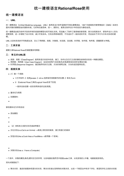
统⼀建模语⾔RationalRose使⽤统⼀建模语⾔⼀:UML统⼀建模语⾔(Unified Modeling Language,UML)是⽤来设计软件蓝图的可视化建模语⾔,1997 年被国际对象管理组织(OMG)采纳为⾯向对象的建模语⾔的国际标准。
它的特点是简单、统⼀、图形化、能表达软件设计中的动态与静态信息。
统⼀建模语⾔能为软件开发的所有阶段提供模型化和可视化⽀持。
⽽且融⼊了软件⼯程领域的新思想、新⽅法和新技术,使软件设计⼈员沟通更简明,进⼀步缩短了设计时间,减少开发成本。
它的应⽤领域很宽,不仅适合于⼀般系统的开发,⽽且适合于并⾏与分布式系统的建模。
UML 从⽬标系统的不同⾓度出发,定义了⽤例图、类图、对象图、状态图、活动图、时序图、协作图、构件图、部署图等 9 种图。
⼆:⼯具安装建模⼯具Rational Rose安装配置参考博客:三:常见的UML图类图:类图(ClassDiagram)是⽤来显⽰系统中的类、接⼝、协作以及它们之间的静态结构和关系的⼀种静态模型。
⽤例图:⽤例图(User Case Diagram):站在系统⽤户(系统⾓⾊)的⾓度吻戏系统存在哪些功能.时序图:(Sequence Diagram):描述程序的执⾏过程,⽅法的调⽤过程,⽅法的返回值等信息。
四:画图实操(1)画⼀个类图:1:打开软件--》选择javaee--》ctrl+s 选择保存类图案列的位置--》取名为crm2:在rational Rose⼯具的Logical View⽬录下实现⼀般来说会创建⼀些⽬录⽤来组织这些类图。
重命名为类图创建画布:修改画布名为市场活动添加属性(2)类和类之间的关系包括6种情况泛化关系(is a:Cat is an Animal -->继承) 类和类的继承,接⼝和接⼝的继承实现关系(like a:Cook likes a FoodMenu-->厨师像⼀个菜单)关联关系(has a : I have a Computer)⼀个类中,关联的属性(⾓⾊)要对应它的作⽤,⽐如电脑在程序员中就是coder⼯具,从玩游戏的⼈中看,电脑就是游戏机。
Flat systems
UML for Embedded Systems Specification and Design: Motivation andOverviewGrant MartinCadence Design Systems2001 Addison Street, Third Floor, Berkeley CA 94704, U.S.A.gmartin@AbstractThe specification, design and implementation of embedded systems demands new approaches which go beyond traditional hardware-based notations such as HDLs. The growing dominance of software in embedded systems design requires a careful look at the latest methods for software specification and analysis. The development of the Unified Modeling Language (UML), and a number of extension proposals in the realtime domain holds promise for the development of new design flows which move beyond static and traditional partitionsof hardware and software. However, UML as currently defined lacks several key capabilities. In this paper, we will survey the requirements for system-level design of embedded systems, and give an overview of the extensions required to UML that will be dealt with in more detail in the related papers. In particular, we will discuss how the notions of platform-based design intersect with a UML based development approach.1. Introduction: The Nature of EmbeddedSystemsModern embedded systems have certain characteristics that demand new approaches to their specification, design and implementation. These approaches must be a combination of traditional hardware and software methods, but must seek new ways of linking them together in order to allow designers to develop such products rapidly and with low risk.These systems are composed of multiple subsystemsor functional units that carry out computation and communication using a heterogeneous set of models of computation. These functional subsystems can be implemented using a variety of components, both hardware and software, composed together into flexible platform architectures. The mapping of function to architecture is not fixed: design space exploration allows developers to find optimal ways of implementing functions by analysis of a variety of alternatives in both hardware and software domains. This emphasises both early modelling of systems, and methods that delay commitment to particular components or implementations to the end of the design process.1.1. HeterogeneousAs technology has developed, embedded systems have moved from single function products to ones incorporating multiple roles. The convergence of functionality from the multiple domains of computing, signal processing of audio and video, and wired and wireless communications have led to increasingly complex embedded systems which integrate subsystems reflecting a heterogeneous set of Models of Computation (MOCs). Modelling such systems requires a set of heterogeneous notations to reflect this: continuous time, finite-state-machine, dataflow, discrete event, reactive, etc. In addition to such heterogeneous logical domains, there are also multiple physical implementation domains in embedded systems – function is realised through combinations of dataflow and control-oriented software, hardware components such as microprocessors, DSPs, analogue and mixed-signal components, digital HW blocks, and RF, optical and MEMS components. These heterogeneous implementation, or ‘architectural’ choices, also need to be modelled.1.2. CompositionalToday’s embedded systems are not usually modelled and implemented monolithically from scratch. Rather they are usually compositions of subsystems, each of which may be based on a different MOC. Each MOC, and modelling notation, is chosen to be ‘natural’ for the subystem domain. Both functional and architectural descriptions of the system may be based on composition of subsystems. With such a design strategy, the emphasis must be equally on the validity of the composition as on the correctness of the constituent parts.1.3. Complexity, Driving Reuse and SynthesisIn line with the ‘convergence’ and ‘compositional’ attributes discussed earlier, modern embedded system products are too complex to be designed from scratch. The complexity of the embedded software for a 3G mobile handset exceeds that of a 2G phone by at least one order of magnitude. Complexity from composing heterogeneous functional requirements demands more design knowledge than many single product groups possess. All these factors point to a strong need to maximise software and indeed system development productivity through use of embedded system platforms and reuse and synthesis methods driven from system-level models [1].1.4. SystemContextAs well as modelling the system from functional requirements through executable specifications, it is important to be able to model the context for an embedded system – both environmental (e.g. channel characteristics and noise scenarios for a wireless system) and user-driven (use-cases for multi-function embedded systems).2. Design Methodology RequirementsIn a related paper in this session [2], embedded and real-time systems design methodologies based on UML and SDL will be discussed. Suffice it here to summarise the basic design methodology requirements based on the characteristics described earlier. We need a methodology to support:•Heterogeneous modelling of system function and architecture, including target implementationSW-HW platforms•The system modelled within its use-context and environment.•Mapping from function to architecture in order to support design space exploration, alternativeimplementations, and reusable components •Strong analytical and verification techniques•Strong linkages from models through to implementation in both SW and HW domains,including synthesis, refinement, decompositionand reuse approaches.3. UML: Capabilities and Lacks3.1. What UML has or will haveWhat makes UML a reasonable meta-language to model embedded/real-time systems, and solve these kinds of design problems? First, from the current UML (1.4)[3,4,5], we can identify several key attributes of UMLimportant to embedded systems:Heterogeneous set of notations• A concept that the UML is not a single language, but a set of notations, syntax and semantics toallow the creation of families of languages forparticular applications. In other words, UML is a‘meta-language’.•Extension mechanisms via profiles, stereotypes, tags, and constraints for particular applications •Use-case modelling to describe system environments, user scenarios, and test cases • A large standards organisation, the Object Modelling Group [4], which is promoting UMLamong software designers and sponsoring itsevolution via task forces, working groups and thelike. OMG also promotes the development ofapplication-domain-specific profiles.•Support for object-oriented system specification, design and modelling, thus appealing to thesoftware community.•Growing interest in UML from the embedded systems and realtime community.•Support for state-machine semantics which can be used for modelling and synthesis•Support for object-based structural decomposition and refinementHowever, UML is not static. It is evolving in manydirections and in particular, there are a number of activitiesrelevant to embedded and real-time systems:•UML 2.0 evolution [2, 6, 7] which is looking at functional encapsulation methods, annotations toUML to allow modelling of real-time aspectssuch as schedulability, performance and time, andother important extensions such as dataflow.•Plans to support SDL, used for many years in realtime and embedded software development, asa profile of UML 2.0 [8].•Action semantics, driven by OMG and the Action Semantics Consortium, which OMG wishes toincorporate into UML 2.0, and that provideformal underpinnings for more completeexecutable specifications and synthesis.•Model-driven architecture [4] that aims to separate the specification of software applicationsfrom the particular middleware ‘platform’ whichimplements them. This is similar to function-architecture codesign.3.2.What UML Lacks and needsGiven existing UML and the evolutions promised inUML 2.0, what are the key lacks remaining to supportembedded systems design [9]? These are:• the platform model• the mapping and refinement methodology tomove from one platform level to another• the constraint definition and budgeting methodology to complement the movement ofdesign from requirements to implementation, andwhich provide a necessary control for optimisation processes in design transformationand synthesis.4. “UML-Platform”Some work has been done on fleshing out the requirements to model SoC platforms in UML, and to develop methodologies for embedded systems design using these concepts [10]. The proposal involves several extensions to UML and assumes that most of the current proposals – for real-time UML and 2.0 extensions – will be accepted and standardised. In this sense, the UML-Platform profile describes the following extensions to UML, as a set of stereotypes and tags:• “uses” and “needs” stereotypes to specifyrealisation relationships between applicationsor platform components, and services offeredby other platform components• a “stack” stereotype to describe hierarchical,layered implementations of platform services• a “peer” stereotype for components and service offerings at the same abstraction level • “coupling” relationships to show necessary linkages between components• tags to define Quality of Service (QoS) parameters for platform services, andapplication requirements. These can bederived from specifications, mapped into constraints, and used to select appropriate implementations. • defined platform layers – Application Specific Programmable (ASP), ApplicationProgramming Interface (API) and Architectural (ARC) within which services canbe classified for deployment• a method for depicting platform “extension points” for future application requirements and new or variant service offerings. The notion of “UML-Platform” thus offers a base for the mapping and refinement concepts which support themove from a target-independent system model to an optimised platform-based implementation. A variety of analysis capabilities can be built using the profile, which allow the notion of ‘software-software’ codesign, in which function is primarily mapped onto a variety of software-based implementations, to be supported. QoS tags allow constraint definition, decomposition into subsystem budgets and the effective choice of possible components that meet overall system requirements.Further research is planned to apply the “UML Platform” profile to commercial SoC platform offerings, and to extend its concepts to support complete UML-basedplatform design methodologies for embedded systems. 5. ConclusionsThe Unified Modelling Language is an interesting and reasonably compelling basis for embedded system design methodology. The current state of the language is not complete enough to build comprehensive tools, flows and methodologies, and the anticipated changes in 2.0, although vital, are still not complete enough to meet all needs. The UML-platform concept, complemented by further work on methodology, should provide much of the additional concepts required for a UML-based embedded and realtime software design flow.6. References 1. Alberto Sangiovanni-Vincentelli and Grant Martin, “Platform-Based Design and Software Design Methodology for Embedded Systems”, IEEE Design and Test ofComputers, Volume 18, Number 6, November-December2001, pp. 23-33.2. Gjalt de Jong, “A UML-Based Design Methodology for Real-Time and Embedded Systems”, DATE 2002, March2002. 3. J. Rumbaugh, I. Jacobson, and G. Booch, The UnifiedModeling Language Reference Manual, Addison-Wesley, 1998.4. The Object Modeling Group, URL: /.5. Thomas Weigert, “What Really is UML?”, presentation, October 18, 1999.6. Bran Selic, “The Real-Time UML Standard: Definition and Application”, DATE 2002, March 2002.7. Bran Selic, “A Generic Framework for Modeling Resources with UML”, IEEE Computer, June 2000, p.64-69. 8. Morgan Björkander, “Graphical Programming Using UML and SDL”, IEEE Computer, December 2000, pp. 30-35.9. Grant Martin, Luciano Lavagno, and Jean Louis-Guerin,“Embedded UML: a merger of real-time UML and co-design”, CODES 2001, Copenhagen, April 2001, pp.23-28.10. Rong Chen, Marco Sgroi, et. al. “Embedded System DesignUsing UML and Platforms”, Unpublished paper, U.C.Berkeley, September, 2001.。
第2章 UML建模技术

2.2.2 Rules of the UML
The
UML's building blocks can't simply be thrown together in a random fashion. Like any language, the UML has a number of rules that specify what a well-formed model should look like. A well-formed model is one that is semantically self-consistent and in harmony with all its related models.
Enterprise information systems Banking and financial services Telecommunications Transportation Defense/aerospace Retail Medical electronics Scientific Distributed Web-based services
2.1.4 The UML Is a Language for Constructing
The UML is not a visual programming language, but its models can be directly connected to a variety of programming languages. This mapping permits forward engineering the generation of code from a UML model into a programming language. The reverse is also possible: You can reconstruct a model from an implementation back into the UML. Things that are best expressed graphically are done so graphically in the UML, whereas things that are best expressed textually are done so in the programming language.
UML建模试题2

UML建模试题2第一套试题一选择题1. 在用例建模中,一些全局的非功能性需求和设计约束应该在哪个需求工件中描述:()A. 用例模型B. 用例规约C. 补充规约D. 词汇表2. 在用UML对系统进行动态建模时,通常使用活动图。
利用活动图有两方面作用:一是对工作流建模,一是对操作建模,此时把活动图作为?()A. 程序流程图B. 系统流程图C. 数据流程图D. 处理流程图3. 在UML中,依赖性也是连接两个类,对其说法正确的是()A. 依赖性总是单向的B. 依赖性不一定是单向的C. 依赖性总是双向的D. 依赖性可以是双向的4. 动作事物是UML模型中的动态部分,他们是模型的动词,代表什么上的动作?()A. 时间和空间B. 时间和对象C. 空间和对象D. 对象5. UML中的分组事物是什么?()A. 视图B. 部署图C. 组件D. 包6. UML支持的建模方式有:(请选择最合理的答案)()A. 静态建模、动态建模B. 动态建模、功能建模C. 静态建模、功能建模D. ABC都支持7. 在用例建模中,用例的粒度、个数以及模型元素之间的关系复杂程度应该由什么指导原则决定?()A. 可理解性B. 模块化C. 用例任务的单一性D. ABC都不是8. 在系统用例建模中,我们判断用例建模工作是否结束的主要标志是:()A. 功能需求的完备性B. 模型是否易于理解C. 是否存在不一致性D. ABC都不是9. 对UML中的包(Package)说法正确且最合理的是:()A. 管理模型复杂度的机制B. 一种容器,包中可以容纳其他任意的模型元素C. 包中可以容纳其他的包D. ABC都对10. 关于UML中的消息描述错误的是:()A. 消息可以从一个对象发向该对象自身。
B. 消息是对象之间的通信。
消息是对象之间的通信。
C. 在序列图中,消息被表示为从一个对象下端引出的垂直虚线。
D. 两个对象间的交互表现为一个对象发送一个消息给另一个对象。
UML Support for Designing Software Systems as a Composition of Design Patterns
1 UML Support for Designing Software Systems as aComposition of Design PatternsSherif M.Yacoub1and Hany H.Ammar21Hewlett-Packard Labs,1501Page Mill,MS1L-15,Palo Alto,CA94304,USAsherif_yacoub@2Computer Science and Electrical Engineering Department,West Virginia UniversityMorgantown,WV26506,USAhammar@Abstract.Much of the research work on design patterns has primarily focusedon discovering and documenting patterns.Design patterns promise early reusebenefits at the design stage.To reap the benefits of deploying these proven de-sign solutions,we need to develop techniques to construct applications usingpatterns.These techniques should define a composition mechanism by whichpatterns can be integrated and deployed in the design of software applications.Versatile design models should be used to model the patterns themselves aswell as their composition.In this paper,we describe an approach called Pat-tern-Oriented Analysis and Design(POAD)that utilizes UML modeling capa-bilities to compose design patterns at various levels of abstractions.In POAD,the internal details of the pattern structure are hidden at high design levels(pat-tern views)and are revealed at lower design levels(class views).We definethree hierarchical traceable logical views based on UML models for developingpattern-oriented designs;namely the Pattern-Level view,the Pattern Interfacesview,and the Detailed Pattern-Level view.The discussion is illustrated by acase study of building a framework for feedback control systems.Keywords:Pattern-Oriented Design,Design Patterns,and Pattern Composition.1IntroductionPatterns are reusable good-quality design practices that have proven useful in the design of software applications[2,11].Patterns can help in leveraging reuse to the design level because they provide a common vocabulary of designs and they are proven design units from which more complex applications can be built.Much work has focused on documenting patterns[e.g.2,11,12,16].Other work is concerned with applying these reusable designs in constructing applications[e.g.3,10,14,15].We can generally classify design approaches that utilize patterns as:2 1.Adhoc.A design pattern records a solution and forces and consequences of apply-ing this solution.However,this is not usually sufficient to systematically develop applications using patterns.For instance,the coincidental use of a Strategy pattern[2] in the implementation of a control application is not a systematic approach to deploy patterns.This is simply because there is no process to guide the development and to integrate the pattern with other design artifacts.2.Systematic.A systematic approach to design with patterns goes further beyond just applying a certain pattern.Systematic approaches can be classified as:a)Pattern Languages.A pattern language provides a set of patterns that solve prob-lems in a specific domain.Pattern languages not only document the patterns them-selves but also the relationships between these patterns.They imply the process to apply the language to completely solve a specific set of design problems.b)Development processes.A systematic development process defines a pattern composition approach,analysis and design steps,design models,and tools to auto-mate the development steps.Such development process produces consistent designs each time the process steps are conducted.We are concerned here with systematic development processes because they are the way to repeatable software design practice.To improve the practice of systematically deploying design patterns,we need to define methodologies to construct applications using patterns and support these methodologies with appropriate modeling languages. In this paper,we discuss a process to develop pattern-oriented applications using UML modeling capabilities.Specifically,we discuss using UML in the Pattern-Oriented Analysis and Design(POAD)process[10,17,31].POAD uses design pat-terns as building blocks.The design of an application is built by gluing together these construction fragments and defining dependencies and collaboration between partici-pating patterns.To make this approach availing,we need to define modeling artifacts that support its automation.Applications developed using this approach are object-oriented in nature.Thus,the Unified Modeling Language[1,13]is used in each step.In this paper,we discuss UML support for modeling design patterns and develop-ing pattern-oriented designs.We show how to use UML modeling capabilities and the POAD process to develop logical design views that capture relationship between pat-terns while hiding details not utilized directly in the design.We then show how to use these views to overlap participants of patterns to produce a denser and a more pro-found class diagram.To illustrate the application of the proposed models and process, we use a case study of building a framework for feedback control systems.2Stringing Versus Overlapping Patterns"It is possible to make buildings by stringing together patterns in a rather loose way.A building made like this,is an assembly of patterns.It is not dense.It is not profound. But it is also possible to put patterns together in such a way that many patterns overlap3 in the same physical space:the building is very dense;it has many meanings captured in small space;and through this density,it becomes profound."[7]In the field of civil engineering,Alexander et.al.discuss techniques for composing patterns as they experienced in making buildings.They compare two approaches: stringing and overlapping patterns.Many of these principles apply to the design of software systems as well.Inspired by Alexander's approaches to make buildings,con-sider the two approaches to build software applications using design patterns:1)Stringing patterns.In this design approach,patterns are glued together to compose an application design.The glue here could simply be UML relationships between patterns as packages(for example dependency between packages)or UML relationships between participants of the patterns(for example UML association, dependency,etc.between classes of one pattern and classes of another pattern).The design is a loose assembly of patterns because it is made by simply stringing patterns and using all the internal participants of a pattern as independent design constructs. The design is neither dense nor profound.It is not dense because we end up with a design that has a large population of classes.It is not profound because many classes have trivial responsibilities.The reason is that the design of many of these patterns has several classes that are only responsible for forwarding to other classes,acting as an interface to the internal design of the pattern,or representing a class that is intended to be part of the external system design not the internal design of the pattern(i.e.a client class of a pattern).2)Overlapping patterns.This approach advocates that many patterns should overlap in the same logical design.Overlapping means that a class,as a participant in one pattern,could be at the same time a participant of another pattern in the same application design.For instance,consider gluing together the Strategy and the Ob-server patterns[2].Overlapping these two patterns could mean that the abstract Strategy class of the Strategy pattern plays the role of abstract Subject class in the Observer pattern.The designer will use one application class to play the role of both participants.As a result,the design is dense and it becomes more profound.It is dense because we end up having fewer classes in the application design than the total number of classes in the patterns used to develop that design.It is profound because each class carries out several responsibilities.With the overlapping patterns approach,we gain the advantage of having less num-ber of classes in the application design than the one produced by stringing patterns. However,there is one salient disadvantage.The pattern boundary is lost and patterns become hard to trace.With stringing patterns,we can always identify the pattern by circling the classes that implement it.When circling the classes of a pattern in the overlapping pattern design,we end up with so many intersecting circles.As an example,consider an application in which the designer has decided to use the Reactor pattern[8]and the Composite pattern[2].We will use these two patterns in the sequel to illustrate the difference between the overlapping and stringing ap-proaches.The class diagram model for each of the two patterns is shown in Figure1.The Reactor pattern is a robust design for a system that receives events,manages a set of event handlers,and dispatches the event to the appropriate handler.It consists of:the abstract EventHandler class which is the interface that all the concrete4event handlers have to comply with;the Reactor class which is the class responsible for scheduling events and dispatching them to event handlers according to the type of the event;and finally thethe Fig.1The class diagram for a)Reactor pattern,and b)Composite patternThe Composite pattern is a robust design for a system that provides a unique inter-face to a complex structure of objects that could be simple or composites.It is com-posed of:the Component class which is the interface for the structure;the Leaf class which implementsthe Component interface but does not contain other objects of type Component ;and finally the Composite class that implements the Compo-nent interface and consists of other components that it manages.Consider the case where we want to use these two patterns in designing a reactive system.When using a Reactor pattern,we might find that the handlers for the applica-tion specific events are not simple objects;instead,they could be complex objects containing other objects that react as well to the events.Hence,we decide to use a Composite pattern for the handlers.Now,how do we glue these two pattern?The first solution is to string the two patterns together by establishing a relationship between the Component class of the Composite pattern and the EventHandler class of the Reactor pattern.By stringing the two patterns,we develop the design shown in Figure 2,which contains all the classes of the two patterns.Fig.The design in Figure 2is not profound because it assumes that the handlers use or reference composite components while in reality the handlers are the composite com-ponents.The second solution is to overlap the two patterns.We overlap the EventHan-dler of the Reactor pattern and the Component class of the Composite pattern and both roles are integrated in one class call it EventHandlerComponent .This class will have the methods from both classes.Consequently,the concrete event handlers become concrete classes derived from the EventHandlerComponent class.The design of the overlapped pattern design is shown in Figure 3The question that rises here is:are these two approaches independent?Must we construct a design that is either a sparse assembly or a condensed overlap of pat-terns?Can we use both?5 ArrayFig.3.Clearly,the first approach,assembling and stringing patterns,is avoided by many designers.This can be attributed to the perceivable disadvantages of simply assem-bling patterns to produce designs.It is,however,an easy approach to practice.The stringing pattern approach provides good traceability from high-level designs,in terms of patterns,to lower-level designs,in terms of classes.We can simply encapsulate the classes of a pattern in one package or a template package[5],which will become the high level view and use the pattern classes in the class diagram model which will be-come the low level design.The Pattern-Oriented Analysis and Design(POAD)approach reaps benefits from both worlds;the stringing and overlapping patterns worlds.It makes use of the sim-plicity and traceability of the stringing-patterns approach and the density and pro-foundness of the overlapping-patterns approach.In POAD,the two approaches are not independent and in fact they could be integrated in one process.POAD starts by as-sembling patterns at a higher level of abstraction using the stringing approach,pro-vides models to trace the patterns to lower levels of abstraction,and then allows the designer to integrate lower level classes to produce dense and profound designs.3Pattern-Oriented Analysis and Design with UMLIn this section,we discuss a pattern oriented analysis and design process that util-izes UML modeling capabilities at various development steps.The following subsec-tions describe each step with application to the development of a feedback control framework.Feedback systems are commonly modeled using block diagrams.The design framework that we develop in this paper is based on design patterns as building constructs.The framework is documented at various design levels using UML models and is reusable as an initial phase in designing feedback control applications.3.1AnalysisThe purpose of this step is to analyze the application requirements and decide on the set of design patterns that will be used in designing the system.To design a feed-back control system,the specification and description of the system configuration and its components must be put into a form amenable for analysis and design.Three basic representations(models)of components and systems are used extensively in the study of control systems:mathematical models,block diagrams,and signal-flow graphs.6Referring to control literature [e.g.9],the generic block diagram of feedback systems represents an initial architecture documentation to start with.Figure 4illustrates the block diagram that is often used to describe a feedback control system.Fig.4.Block diagram for a feedback control systemThe portion of a system to be controlled is usually called the Plant .An output vari-able is adjusted as required by the error signal.This error signal is the difference between the system response as measured by the feedback element and the reference signal,which represent the desired system response.Generally,a controller is required to process the error signal such that a certain control strategy will be ing the generic block diagram of a closed loop control system,the system is decomposed into:a feedforward component that processes the error data and applies a control algorithm to the plant;a feedback component that measures data from the plant,proc-esses it,and provides the feedback data;an error calculation component that com-pares the input and feedback data and produces the error;and the plant that is an ex-ternal component on which control is applied and from which measurements are taken.3.2Pattern SelectionWe analyze the responsibilities and the functionalities of each component and iden-tify candidate patterns that could provide a design solution for each component.In doing so,we have considered the design problem that we want to solve and match it to the solution provided by general purpose design patterns [e.g.2,11,12]:1.The feedforward component implements some sort of a control strategy.Thechange in the control strategy should be flexible and hidden from any calls and invocations form any other component.For example,the feedforward component should provide the same interface to the rest of the components in the system while the framework can provide the flexibility to plug in and plug out different control strategies.If we consider this as the design problem that we want to solve and search for patterns whose intent is to solve similar problems,we find that a Strategy pattern [2,pp315]is a good candidate for this task.2.The feedback component receives measurements and applies a feedback controlstrategy.It feeds the result to the error calculation component.The measurement unit observes and measures data from the plant and feeds it to the feedback branch.Thus,measurement observations can be communicated to the feedback controller using the Observer pattern [2,pp293].Thus we can use the Observer pattern to loosen the dependency between the objects doing the plant observation and those actually doing the feedback control.The measured data is fed to the feedback control strategy,which -similar to the feedforward component-shouldReferenceInput7 provide flexibility to plug in and plug out different feedback control strategies.This can be implemented using another Strategy pattern[2,pp315].3.In the error calculation component,the feedback controller notifies the errorcalculation unit with the feedback data.The feedback controller can be viewed as the subject that notifies the error calculator with changes in the feedback data.Error calculation is done whenever feedback data becomes available,at that mo-ment,this data is compared with the persistent input data.Thus,an Observer pat-tern[2,pp293]can implement this behavior.4.If we examine the data manipulated in the feedback system,we find that the sys-tem handles:measurement data that is measured from the plant;feedback data that is the result of processing the measured data by the feedback element;and fi-nally the error data that is the result of processing the feedback data and the input data.Data of different types need to be exchanged between the framework com-ponents.We can use a Blackboard pattern(a modified version of the blackboard patterns in[24,11])for managing the system repository.In choosing these patterns,we consider how the pattern solves the design problem and the intent of the pattern.In summary,a Strategy pattern is selected for the feed-forward component,an Observer and a Strategy pattern are selected for the feedback component,an Observer pattern is selected for the error calculation component,and a Blackboard pattern is selected as the system repository.In this small example,it was obvious which patterns could be used.In other complex example,the analyst could use UML use cases and sequence diagrams to understand the functionality required by each component.3.3Constructing Pattern-Level DiagramsIn this step,we create instances of the selected patterns and identify the relation-ships between these instances.As a result,a Pattern-Level diagram of the system is developed.First,we create pattern instances.In the previous step,we have selected to use two Strategy patterns one in the feedforward component and the other in the feedback component.Thus,we use the instances FeedforwardStrategy and FeedbackStrategy of type Strategy pattern in the design of the feedforward and feedback components respectively.We have also selected to use two Observer patterns one for the feedback component and the other for the error calculation component.Thus,we use a Feed-backObserver instance of type Observer pattern to observe and measure data from the plant and an ErrorObserver instance of type Observer pattern to calculate the error. We use a Blackboard of type Blackboard pattern to manage the system data reposi-tory.This is just giving domain specific names to abstract patterns types(templates).Second,we define dependency relationships between pattern instances.The Feed-backObserver uses the FeedbackStrategy to apply a feedback control algorithm, which in-turn,uses the ErrorObserver to calculate the error.The ErrorObserver uses the FeedforwardStrategy to apply a forward control algorithm.The Blackboard is used by all patterns to store and retrieve data.8 Finally,we use the pattern instances and their relationships to construct the Pat-tern-Level diagram asto show the typeof the pattern instance.Fig.5.AThe product of this process is the Pattern-Level diagram of the framework.It de-scribes the architecture of a feedback system using design patterns,which explains why the names"Pattern-Oriented Analysis and Design"is used.During the design or design refinement phases we could discover that a selected pattern has limitations or impacts on other design aspects.In this case,the designer would revisit this design level to choose another pattern,replace previous choices,or create a new pattern de-pendency or a new uses relationship.3.4Constructing Pattern-Level with Interfaces DiagramIn this step,the dependency relationship between patterns in the Pattern-Level view is further traced to lower level design relationships between pattern interfaces.First,we declare interfaces for the patterns used in each Pattern-Level diagram (only one diagram for the feedback system).The Strategy pattern has the class Con-text as the interface to the encapsulated control strategy.The Observer has two interfaces that allow coordinating the subject observed with its observer.These inter-faces are implemented by the notify()interface in the subject and the update() interface in the observer.The Blackboard pattern has the interfaces to get and store data in the repository,these interfaces are implemented by the getData()and setData()methods.Then,we identify the relationship between pattern interfaces by translating all dependency relationships between patterns in a Pattern-Level dia-gram to relationships between interface classes and/or interface operations.The prod-uct of this process is the Pattern-Level with Interfaces diagram.Figure6illustrates the Pattern-Level with Interface diagram for the feedback control framework.As an example consider the relationship between the FeedbackObserver and the FeedbackStrategy pattern instances in the Pattern-Level view.The relationship be-tween these two patterns at the Pattern-Level view is that the FeedbackObserver uses the FeedbackStrategy to apply a feedback control strategy whenever the measurement data is ready.The interfaces of the FeedbackObserver are the Update()and theData9 notify()interface methods.The interface of the FeedbackStrategy is the Con-text interface class.Thus the relationship between these two patterns is translated to a relationship between the Update()interface of the earlier and the Context inter-face of the latter.Similarly,all pattern relationships of Figure5are translated to rela-tionshipsFig.6.A3.5Constructing Detailed Pattern-Level Diagrams ArrayFig.7.A Detailed Pattern-Level diagram for feedback control systems10 To construct the Detailed Pattern-Level diagram,we express the internals(i.e.par-ticipants)of each instantiated pattern in the Pattern-Level with Interfaces diagram. Since we have used pervasive design patterns in developing the feedback control framework,their structure can be found in the literature.For example,the class dia-gram model for the Strategy and Observer patterns is documented in[2].Figure7 illustrates the Detailed Pattern-Level diagram for the feedback pattern-oriented frame-work.Note that we do not take any additional design decisions in this step.With the appropriate tool support Figure7is a direct generation from the Pattern-Level with Interfaces diagram by simply retrieving the class diagram model from a pattern data-base.3.6Instantiating Pattern InternalsIn this step,we add domain specific nature to the Detailed Pattern-Level diagrams by renaming internal pattern classes according to the application domain,choosing names for pattern participants that are meaningful in the application context,and de-fining domain specific names for operations in the patterns.Due to space limitation, we will illustrate few examples only in the sequel.Instantiating the ErrorObserver PatternThe errorwhich iscomposed of:Fig.8.Instantiating the ErrorObserver pattern• AbstractObserver.An updating interface for objects that are notified of changes in the subject.• AbstractSubject.An interface for attaching and detaching observers.It knows about its observers that ought to be notified of a subject's change.• ErrorObserver.It is a concrete observer that maintains a reference to the FeedbackSubject,reads the feedback data after being processed by the feedback strategy,analyzes the feedback data with respect to the reference input data,and stores the error in the blackboard.It implements AbstractObserver update interface.• FeedbackSubject.It is a concrete subject that sends notification to the con-crete observers of new data received from the feedback component.Instantiating the FeedbackObserver PatternThe FeedbackObserver is used in the feedback component and is composed of:• AbstractObserver and AbstractSubject.They play an interface role similar to that of the ErrorObserver pattern.11• MeasurementSubject.It receives measurement notifications from the plant and notifies its observer FeedbackObserver that a measurement is ready.• FeedbackObserver.When notified by changes in the plant(through the MeasurementSubject),it pulls the data identifier from the subject(using thepull mode of theto process themeasured data.Fig.9.Instantiating the FeedbackObserver patternInstantiating theFig.10.Instantiating the FeedbackStrategy patternThe FeedbackStrategy pattern is composed of:• Feedback.It is the context of the feedback control strategy.It is configured with a feedback control strategy object through a reference to an FBAbstractCon-troller.• FBAbstractController:It is the interface for all feedback control strate-gies.The Feedback uses this interface to call the feedback concrete algorithm.• FBControlStrategyA,and FBControlStrategyB.They represent concrete implementations for feedback control strategies.The FeedbackObserver invokes the control routine of the Feedback that ap-plies the feedback control strategy required from the component.The Feedback class interacts with the FeedbackSubject of the observer pattern in the error calculation component and invokes its notify()procedure.This establishes the link between the feedback component and the error calculation component.Two features can help the designer keep track of the patterns.First,the three mod-els Pattern-Level diagram,the Pattern-Level with Interfaces diagram,and the De-tailed Pattern-Level diagram provide a documentation of the framework as a composi-tion of patterns.Second,with the appropriate tool support,the renaming process is not an editing process.In editing we simply change the names and the old names are lost. But in the renaming process of a class,the tool support for POAD should provide a12 system with memory to keep the history of the changed name specifically in pattern instantiation.3.7Developing an Initial Class DiagramFrom the Detailed Pattern-Level diagram,we use pattern interfaces and the instan-tiated details of pattern internals to construct a UML class diagram.The class diagram that is developed at this phase is an initial step to develop the static design model of the pattern-oriented framework.Figure11illustrates the class diagram for the frame-work.It can be recognized that the patterns are still notable in the class diagram as shown by the dotted boxes around the classes.As part of POAD,all the models in Figure6through Figure11are saved as analysis and design models.It is the role of aThe class diagram obtained from gluing patterns together at the high-level design is neither dense nor profound because we just stringed the patterns together.It has many replicated abstract classes due to the fact that we used multiple instances of the same pattern.For example we used the FeedbackStrategy and the FeedforwardStrategy instances of type Strategy pattern.It also has many classes with trivial responsibilities because many classes are just doing forwarding of messages to internal participants of the pattern.In the following step we use reduction and grouping mechanisms to opti-mize the UML design diagrams obtained initially in the previous step.3.8Design RefinementThe complexity of the framework can be reduced by eliminating replicated abstract classes.A pattern has one or more abstract classes.Since the same pattern type is。
UML术语中英对照表
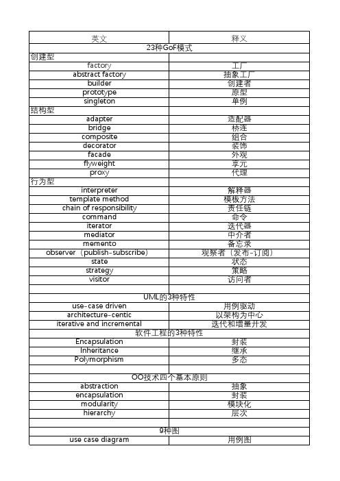
UML的3种特性 use-case driven architecture-centic iterative and incremental
软件工程的3种特性
Encapsulation Inheritance
Polymorphism
用例驱动 以架构为中心 迭代和增量开发
封装 继承 多态
英文 23种GoF模式
创建型 factory
abstract factory builder
prototype singleton 结构型 adapter
bridge composite decorator
facade flyweight
proxy 行为型
interpreter template method chain of responsibility
command iterator mediator
memento observer(publish-subscribe)
state strategy visitor
释义
工厂 抽象工厂 创建者
原型 单例
适配器 桥连 组合 装饰 外观 享元 代理
解释器 模板方法 责任链
命令 迭代器 中介者 备忘录 观察者(发布-订阅)
façade framwork general ordering generalizable element generation granularity graphic marker group transition guillemets hibernate hyperlink implementation indeterminacy indirect instance indirect substate inheritance instantiation
Utility of the UML
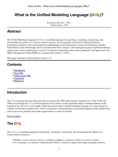
What is the Unified Modeling Language (U M L)?By Sinan Si Alhir (July 1, 1998)Updated August 1, 1998AbstractThe Unified Modeling Language (U M L) is a modeling language for specifying, visualizing, constructing, and documenting the artifacts of a system−intensive process. It was originally conceived by Rational Software Corporation and three of the most prominent methodologists in the information systems and technology industry, Grady Booch, James Rumbaugh, and Ivar Jacobson (the Three Amigos). The language has gained significant industry support from various organizations via the U M L Partners Consortium and has been submitted to and approved by the Object Management Group (OMG) as a standard (November 17, 1997).This paper elaborates on the definition of the U M L.Contents• Introduction• The UML• Utility of the UML• Conclusion• ReferencesIntroductionThe U M L emerged from the unification that occurred in the 1990s following the "method wars" of the 1970s and 1980s. Even though the U M L evolved primarily from various second−generation object−oriented methods (at the notation level), the U M L is not simply a third−generation object−oriented modeling language. Its scope extends its usability far beyond its predecessors. And it is experience, experimentation, and gradual adoption of the standard that will reveal its true potential and enable organizations to realize its benefits.Return to ContentsThe U M LThe U M L is a modeling language for specifying, visualizing, constructing, and documenting the artifacts of a system−intensive process.• Within a system−intensive process, a method is applied as a process to derive or evolve a system.• As a language, it is used for communication. That is, a means to capture knowledge (semantics) about asubject and express knowledge (syntax) regarding the subject for the purpose of communication. The subject is the system under discussion.• As a modeling language, it focuses on understanding a subject via the formulation of a model of the subject (and its related context). The model embodies knowledge regarding the subject, and the appropriateapplication of this knowledge constitutes intelligence.• Regarding unification, it unifies the information systems and technology industry’s best engineering practices across types of systems (software and non−software), domains (business versus software), and life−cycleprocesses.• As it applies to specifying systems, it can be used to communicate "what" is required of a system, and "how"a system may be realized.• As it applies to visualizing systems, it can be used to visually depict a system before it is realized.• As it applies to constructing systems, it can be used to guide the realization of a system similar to a"blueprint".• As it applies to documenting systems, it can be used for capturing knowledge about a system throughout its life−cycle.The U M L is not:• A visual programming language, but a visual modeling language.• A tool or repository specification, but a modeling language specification.• A process, but enables processes.Fundamentally, the U M L is concerned with capturing, communicating, and levering knowledge.Return to ContentsUtility of the U M LThe U M L is an evolutionary general−purpose, broadly applicable, tool−supported, and industry−standardized modeling language. It applies to a multitude of different types of systems, domains, and methods or processes.• As a general−purpose modeling language, it focuses on a core set of concepts for acquiring, sharing, andutilizing knowledge coupled with extensibility mechanisms.• As a broadly applicable modeling language, it may be applied to different types of systems (software andnon−software), domains (business versus software), and methods or processes.• As a tool−supported modeling language, tools are readily available to support the application of the language to specify, visualize, construct, and document systems.• As an industry−standardized modeling language, it is not a proprietary and closed language but an open and fully extensible industry−recognized language.The U M L enables the capturing, communicating, and leveraging of strategic, tactical, and operational knowledge to facilitate increasing value by increasing quality, reducing costs, and reducing time−to−market while managing risks and being proactive in regard to ever−increasing change and complexity.Return to ContentsConclusionBecause the U M L evolved primarily from various second−generation object−oriented methods (at the notation level), most practitioners of the U M L believe that it is only concerned with object−oriented software−systems; when actually, the U M L is not simply a third−generation object−oriented modeling language but a "unified modeling language" concerned with systems in general.The success of the U M L will be measured by its appropriate use on successful projects. The U M L does not guarantee success, but enables practitioners to focus on delivering value using a consistent, standardized, and tool−supported modeling language.Return to ContentsReferences[Alhir]Sinan Si Alhir. "U M L in a Nutshell : A Desktop Quick Reference". O’Reilly Associates, Inc., 1998. Return to ContentsEmail salhir@Web Site /~salhirCopyright © 1998 Sinan Si Alhir. All rights reserved.。
面向对象的分析与设计方案简介

常用用例来收集和描述用 户的需求
标识类及类的属性和服务
描述系统的静态结构 描述系统的动态行为
a Nanjing University
2021/1/5
需求分析
15
Waterfall式开发其需求分析一开始(其实是过早地)确定的 features 在最终产品中真正采用情况的比例
a Nanjing University
7
Booch Coad/Yourdon OMT:对象模型,
功能模型,动态 模型 Jacobson UML
三种基本活动
识别类和对象
描述对象和类之间 的关系
通过描述每个类的 功能定义对象的行 为
a Nanjing University
2021/1/5
面向对象方法
8
Rational Unified Process (RUP)– Rational统一开发 过程
The + in the FURPS+: Implementation requirements:
“Must use Linux and Java”
a Nanjing University
2021/1/5
面向对象分析
20
OOA模型
基本模型(类图)
交
对象层
主
互
题
图
特征层
图
关系层
详细说明
a Nanjing University
专家建议 目前/未来的需求
领域 分析
类的分类 复用标准 功能模型 领域语言
领域 分析 模型
a Nanjing University
2021/1/5
13
a Nanjing University
General Terms

Using UML To Visualize Role-Based Access ControlConstraintsIndrakshi Ray Computer Science Dept. Colorado State University Fort Collins,CO80523 iray@Na LiComputer Science Dept.Colorado State UniversityFort Collins,CO80523na@Robert FranceComputer Science Dept.Colorado State UniversityFort Collins,CO80523france@Dae-Kyoo KimComputer Science Dept.Colorado State UniversityFort Collins,C080523dkkim@ABSTRACTOrganizations use Role-Based Access Control(RBAC)to protect information resources from unauthorized access.We propose an approach,based on the Unified Modeling Language(UML),that shows how RBAC policies can be systematically incorporated into an application design.We consider an RBAC model to be a pattern which we express using UML diagram templates;RBAC policies for an application conforming to this model can be generated by instantiating these templates with values obtained from the appli-cation.The constraints of the RBAC model are expressed using the Object Constraint Language(OCL).OCL constraints,based on first-order logic,are difficult to understand.To alleviate this prob-lem,we show how violation of such constraints can be visually represented using object diagram templates.With adequate tool support,developers can use these to demonstrate constraint viola-tions in their applications.Our approach is illustrated using a small banking application.Categories and Subject DescriptorsD.2.1[Requirements/Specifications]:[Languages,Methodologies]; K.6.5[Management of Computing and Information Systems]: [Security and Protection]General TermsDesign,Languages,SecurityAny opinions,findings,and conclusions,or recommendations ex-pressed in this publication are those of the authors and do not nec-essarily reflect the views of AFOSR.Permission to make digital or hard copies of all or part of this work for personal or classroom use is granted without fee provided that copies are not made or distributed for profit or commercial advantage and that copies bear this notice and the full citation on thefirst page.To copy otherwise,to republish,to post on servers or to redistribute to lists,requires prior specific permission and/or a fee.SACMAT’04,June2–4,2004,Yorktown Heights,New York,USA. Copyright2004ACM1-58113-872-5/04/0006...$5.00.KeywordsModeling,RBAC,UML1.INTRODUCTIONRole-Based Access Control(RBAC)[10]is used by organiza-tions to protect their information resources from unauthorized ac-cess.In RBAC,users are assigned to roles and roles are associated with permissions.A permission determines what operations a user assigned to a role can perform on information resources.In addi-tion,various kinds of constraints can be specified in RBAC.A lot of research appears in the area of specification of policies [3,4,5,7,8,13,14,15,16,23,22,26].Some researchers[3,4, 5,7,13,16,23]use formal logic for specifying security policies; others[14,15,22,26]use high level languages.Since formal-logic based approaches are difficult to use and understand,application developers are unlikely to use them.High-level languages are easy to use and understand,but are not amenable for analysis.A lan-guage is needed that is easy to understand and use,and also allows for the analysis of policy specification.Researchers[12,27,28]have often advocated that security poli-cies must be kept separate from the application.This allows secu-rity requirements to be clearly documented,policies to be changed independently of the application,policies to be independently an-alyzed,and policies to be centrally managed.Specifying policies independently creates an additional problem–how to integrate the policy concerns in an application.Thus,there is an additional re-quirement of policy specification language:the language should also allow the policy specification to be methodically integrated with the application.In this work,we show how the Unified Modeling Language(UML) [29]can be used to specify RBAC policies.UML is the de facto modeling language used in the software industry.UML is easy to use and understand and is also amenable to analysis.Other re-searchers[2]have also advocated the use of UML for specifying RBAC policies.For instance,Ahn and Shin[2]show how RBAC constraints can be expressed in UML using the Object Constraint Language(OCL)[31].However,they do not provide a systematic modeling approach that can be used by developers to create appli-cations with RBAC features.We present an approach for systematically incorporating RBACpolicies into an application design model that is specified using UML.We use UML diagram templates to specify patterns of reusable RBAC policies.The patterns describe reusable structures and con-straints that developers can use to describe their application-specific RBAC policies.Class diagram templates are used to describe RBAC entities(e.g.,user,permission,session)and their relationships.Ap-plying an RBAC pattern in an application domain involves binding the template parameters to design elements in the domain.To aid in the analysis of policies,RBAC constraints can be speci-fied using the Object Constraint Language(OCL).OCL is based on first order logic which is not much comprehensible to the ordinary user.We provide an approach for visualizing RBAC constraints; this makes it easier for the end users to recognize problems with the constraints.Developers can specify application specific RBAC constraints as object diagrams.To assist in the task of identify-ing conflicts we provide object diagram templates that describe ob-ject structure patterns that describe violations to RBAC constraints. These patterns can be used by developers to check for the presence of policy violations.Note that,other researchers[24,30]have also focussed on visu-alization of access control policies.Osborn and Guo[24]use group and role graphs,and Tidswell and Jaeger[30]use a set-based nota-tion.Unlike the technique described in this paper,these approaches use their own notations and could require some effort to integrate with the industry-based standard notations.The rest of the paper is organized as follows.In Section2,we give a brief overview of RBAC and UML.In Section3we present a generic RBAC model expressed as a class diagram template.Sec-tion4describes how to use object diagram templates to specify RBAC constraints.Section5illustrates how the violation patterns described by object diagram templates can be used to detect viola-tions in application-specific RBAC policies.An overview of related work is provided in Section6.Section7concludes the paper.2.BACKGROUND2.1Role-based Access ControlRBAC is used to protect information objects(henceforth referred to as objects)from unauthorized users.To achieve this goal,RBAC specifies and enforces different kinds of constraints.Fig.1de-scribes the general model of RBAC.RBAC has three components: base model,role hierarchies,and constraints.The base model embodies the essential aspects of RBAC.The base model requires that users(human)be assigned to roles(job function),roles be associated with permissions(approval to per-form an operation on an object),and users acquire permissions by being members of roles.The base model also includes the notion of user sessions.A user establishes a session during which he ac-tivates a subset of the roles assigned to him.Each user can ac-tivate multiple sessions;however,each session is associated with only one user.The operations that a user can perform in a session depend on the roles activated in that session and the permissions associated with those roles.Role hierarchies define an inheritance relation among the roles in terms of permissions and user assignments.In other words,role r1inherits role r2only if all permissions of r2are also permissions of r1and all users of r1are also users of r2.Constraints are an important aspect of RBAC and are sometimes argued to be the principal motivation for RBAC.The common ex-amples of RBAC constraints include static separation of duty,dy-namic separation of duty,prerequisite roles,and cardinality con-straints.These constraints will be explained when we describe our approach for specifying RBAC constraints later in this paper.2.2Unified Modeling Language(UML)The UML is a standard modeling language maintained by the Object Management Group(OMG)(See /uml for details).The UML defines notations for building many dia-grams that each presents a particular view of the artifact being mod-eled.In this paper we utilize the following diagram types:Class Diagram:A class diagram depicts the static structural as-pects of an artifact being modeled.It describes the conceptsand the relationships between them.Relationships are ex-pressed using associations and generalizations/specializations.are described in terms of their properties,where a propertycan be represented by an attribute,a behavioral unit(an op-eration),or a relationship with another concept.Object Diagram:A static object diagram is an instance of a class diagram;it shows a snapshot of the detailed state of a systemat a point in time.In this paper,we use object diagrams bothto capture RBAC constraints and to model system specificsecurity policies.3.MODELING RBACIn this section we specify RBAC in terms of UML template classes.A template class diagram is a class descriptor with pa-rameters.A class diagram is obtained from a template diagram by binding the parameters to values.Fig.2shows a class diagram template describing hierarchical RBAC with SSD and DSD.The symbol“”is used to indicate parameters to be bound.We use this notation when there is a large number of parameters that makes useof the standard UML parameter list cumbersome.Class templates are associated with attribute templates(e.g.,Name: String in Role)and operation templates(e.g.,GrantPermission in Role).Association templates(e.g.,UserAssignment)consist of parameters for association names and association-end multiplici-ties.The OCL constraints in Fig.2restrict the values that can be bound to multiplicity parameters.For example,o.lowerbound=1restricts the multiplicities that can be bound to the parameter oto ranges that have a lower bound of1.The multiplicity“1”on the UserSessions association-end attached to User is strict:a session can only be associated with one user.The User class template represents users.A user can create a new session(CreateSession),delete a session(DeleteSession),as-sociate self with a new role AssignRole and remove an associated role(DeassignRole).The operation AssignedRoles returns the setof roles directly assigned to the user while the operation Authorize-dRoles returns the set of roles directly assigned to the user as well as those roles that are inherited by the directly assigned roles.The class templates Role,Session,and Permission are similarly speci-fied.Association templates,such as UserAssignment and SessionRoles produce associations between instantiations of the class templates they link.A UserSessions link(i.e.,an instance of an association obtained by binding the parameters of UserSessions to values)is created by a CreateSession operation(i.e.,an operation obtained by binding the operation template parameters to values)and deleted by a DeleteSession operation.The AssignRole operation creates a UserAssignment link;the DeassignRole operation removes a UserAs-signment link.Each operation template is associated with an OCL template ex-pression that produces OCL pre-and post-conditions when the tem-plate parameters are bound to values.Pre-and post-condition tem-plates associated with the CreateSession and GrantPermission op-eration templates are given below:user_sessionssession_rolesRoleSUSERSPermission Assignment(PA)(UA)User AssignmentRole Hierarchy SSD (RH)DSDSESSIONSOPSOBSPRMSFigure 1:Describing the different components of RBACFigure 2:RBAC class diagram templatecontext User::CreateSession():(s:Session)post:result=s ands.oclIsNew()=true andself.Session includes(s)context Role::GrantPermission(p:Permission)pre:self.Permission excludes(p)post:self.Permission includes(p)For a detailed description of how to use the templates to incorpo-rate RBAC features into an application,please refer to our previous work(e.g.,see[25,18]).4.MODELING RBAC CONSTRAINTS Constraints are an important aspect of RBAC.Consequently,wefocus on the specification of constraints.We can specify constraints using OCL in class diagram templates(as is done in Fig.2).Al-ternately,one can visualize constraints using object diagram tem-plates.We employ both techniques.The OCL approach is formal and precise;while visualization of constraints makes it easier to understand and recognize violation of those constraints.In our visualization approach,we create object diagram tem-plates that describe object structure patterns that are violations of RBAC constraints.These patterns can be used by developers to check for the presence of constraint violations.Developers can specify application specific security policies as object diagrams. Presence of invalid patterns in object diagrams that represent se-curity policies indicate problems with the specification of security policies.Our expression includes separation of duty constrains,prerequi-site constraints,and cardinality constraints.4.1Separation of Duty ConstraintsSeparation of duty constraints are used to enforce conflict of in-terest policies.Static separation of duty(SSD)constraints aim to prevent conflict of interests that arise when a user gains permissions associated with conflicting roles(roles that cannot be assigned to the same user).SSD constraints are specified for any pair of roles that conflict.SSD constraints place constraint on the assignment of users to roles,that is,membership in one role that takes part in an SSD constraint prevents the user from being a member of the other conflicting role.We refer to this type of constraints as SSD-Role constraints.SSD-Role constraints may exist in the absence of role hierarchies or in the presence of role hierarchies.A role hier-archy defines inheritance relationships between roles.Through the inheritance relationship,a senior role inherits the permissions of its junior roles and any user assigned to the senior role is also assigned to the junior roles.The presence of role hierarchies complicates the enforcement of the SSD-Role constraints:before assigning users to roles not only should one check the direct user assignment but also the indirect user assignment that occurs due to the presence of the role hierarchies.An SSD-Role constraint is expressed as follows using the OCL template notation:SSD-Role constraint:Conflicting roles cannot be assigned to the same user.context SSDRole inv:er excludesAll(er)Alternately,SSD-Role constraint violations can be visualized using object diagram templates as in Fig.3.Fig.3a describes structures in|SSDRole<<invalid>>|r1 : |Role|senior|senior|junior(a) Violation of the SSD constraint in the absence of role hierarchies(b) Violation of the SSD constraint in the presence of role hierarchies|r2 : |Role|RoleHierarchy|r1 : |Role<<invalid>>|r1 : |Role|SSDRole|r2 : |Role|junior|RoleHierarchy|RoleHierarchy|r2 : |Role|u1 : |User|UserAssignment|UserAssignment<<invalid>>|r1 : |Role|SSDRoleFigure3:Using UML object diagram templates to show SSD-Role constraint violationswhich a user is assigned to roles in an SSD-Role constraint;Fig.3b describes structures in which two roles connected by a hierarchy are also involved in an SSD-Role constraint,or two roles that are in an SSD constraint have the same senior role.Dynamic separation of duty(DSD)constraints aim to prevent conflict of interests as well.DSD constraints place restrictions on the roles that can be activated within the same user session.If one role that takes part in a DSD constraint is activated,the user cannot activate the other conflicting role in the same session.We refer to these types of constraints as DSD constraints.A DSD constraint is expressed using the OCL template notation as follows:DSD constraint:Conflicting roles cannot be activated in thesame session.context DSD inv:r1.Session excludesAll(r2.Session)Alternately,DSD constraint violation can be visualized using ob-ject diagram template as in Fig.4.Fig.4describes structures in which two roles in a DSD constraint are activated in the same ses-sion(violation of DSD constraints).This conflicting notion can be applied to other elements such as user and permission in RBAC.The concept of conflicting per-missions defines conflicts in terms of permissions rather than roles. Constraints of conflicting permissions are referred to SSD-Permission constraints.SSD-Permission constraints place constraint on the permissions that can be assigned to roles.Assignment of a per-mission that takes part in an SSD-Permission constraint to a role prevents the other conflicting permission being assigned to the role. Similarly,the concept of conflicting users defines conflicts in terms of users rather than roles.Constraints of conflicting users are re-ferred to SSD-User constraints.SSD-User constraints place con-straint on the users that can be assigned to roles.Assignment of a user that takes part in an SSD-User constraint to a role prevents<<invalid>>|s1 : |Session|r1 : |Role |r2 : |Role|DSD|SessionRoles|SessionRolesFigure 4:Using UML object diagram template to show DSD constraint violationthe other conflicting user being assigned to the role.The SSD-Permission and SSD-User constraints are expressed using OCL template expressions as follows:SSD-Permission constraint:Conflicting permissions cannot be assigned to the same role.context SSDPerm inv :p1.Role excludesAll(p2.Role)SSD-User constraint:Conflicting users cannot be assigned to the same role.context SSDUser inv :u1.Role excludesAll(u2.Role)|p1 : |Permisson<<invalid>>|p2 : |Permisson|PermAssignment|PermAssignment|r1 : |Role|SSDPermFigure 5:Using UML object diagram template to show SSD-Permission constraint violation|UserAssignment|UserAssignment<<invalid>>|u2 : |User|u1 : |User |r1 : |Role|SSDUserFigure 6:Using UML object diagram template to show SSD-User constraint violationAlternately,SSD-Permission and SSD-User constraints can bevisualized using object diagram template as in Fig.5and Fig.6.Fig.5describes the structure in which a role is assigned to permis-sions in an SSD-Permission constraint (violation of SSD-Permission constraints).Fig.6describes the structure in which two users in an SSD-User constraint are assigned to the same role (violation of SSD-User constraints)4.2Prerequisite ConstraintsThe concept of prerequisite roles is based on competency and appropriateness.Prerequisite constraints require that a user can be assigned to a role only if the user is already assigned to the role’s prerequisites.We refer to such constraints as Prerequisite-Role constraints.Figure 7:Using UML object diagram template to show Prerequisite-Role constraint violationFigure 8:Using UML object diagram template to show Prerequisite-Permission constraint violationThis notion of prerequisite can also be applied to other elements such as permission in RBAC.The concept prerequisite permissions requires that a permission can be assigned to a role only if the role already possesses the permission’s prerequisites.We refer to such constraints as Prerequisite-Permission constraints.Prerequisite-Role and Prerequisite-Permission constraints are expressed using OCL template expressions as follows:Prerequisite-Role constraint:A user can be assigned to a role only if the user is already assigned to the role’s prerequisites.context PrerequisiteRole inv :er includesAll(er)Prerequisite-Permission constraint:A permission can be as-signed to a role only if the role already possesses the permis-sion’s prerequisites.context PrerequisitePerm inv :p1.Role includesAll(p2.Role)Alternately,Prerequisite-Role and Prerequisite-Permission constraints can be visualized using object diagram template as in Fig.7and Fig.8.Fig.7describes the structure in which a user is assigned to a role without being assigned to the role’s prerequisite (violation of Prerequisite-Role constraints).Fig.8describes the structure in which a role is assigned to a permission without being assigned to the permission’s prerequisite (violation of Prerequisite-Permission constraints).|UserAssignment|UserAssignment<<invalid>>|r1 : |Role|u1 : |User |u2 : |UserFigure 9:Using UML object diagram template to show cardi-nality constraint violation4.3Cardinality ConstraintsAnother constraint type is cardinality constraints.Cardinality constraints can be used to restrict,for example,the number of users that can be assigned to a role,the number of roles a user can play,the number of roles a permission can be assigned to,or the number of sessions a user is allowed to activate at the same time.Cardi-nality constraints place constraint on the relationship between ele-ments.They restrict the number of elements that can be related to each other.This numerical limitation may vary depending upon organiza-tional policies.For example,we may have one type of organiza-tional policies stating that there is at most one person in a role.Fig.9shows the specification of this type of constraints.Fig.9describes the structure in which two users are assigned to a role which,according to a cardinality constraint,should have at most one user assigned to it (violation of cardinality constraints).5.IDENTIFYING CONFLICTS IN SYSTEM-SPECIFIC RBAC POLICIESIn this section we illustrate how the violation patterns shown in the previous section can be used to identify policy conflicts.If the violation pattern exists in an object diagram describing a system-specific policy,then a conflict exists.Checking for the presence of a pattern in an object diagram specifying a set of policies is essen-tially a search for a sub-graph in an object diagram.To illustrate our approach we use a simple banking application taken from [6].The application is used by various bank officers to perform transactions on customer deposit accounts,customer loan accounts,ledger posting rules,and general ledger reports.A set of system-specific RBAC policies for the banking system is given below:Core policies:The roles of the banking system (instances of BankRole )are teller ,customerServiceRep ,accountant ,account-ingManager and loanOfficer .The permissions assigned to these roles are given below:P1A teller can modify customer deposit accounts.P2A customer service representative can create or delete customerdeposit accounts.P3An accountant can create general ledger reports.P4An accounting manager can modify ledger-posting rules.P5A loan officer can create and modify loan accounts.Hierarchical policies:The hierarchical policy in the banking application is stated below:H1Customer service representative role is senior to the teller role.SSD-Role policies:For the banking system the following pairs of roles are conflicting:(teller,accountant),(teller,loanOfficer),(loanOfficer,accountant),(loanOfficer,accountingManager),(customerServiceRep,accountingManager)DSD policies:For the banking system the following pair of roles is in DSD relation:(customerServiceRep,loanOfficer)Prerequisite-Role policies:For the banking system the follow-ing pair of roles is in a prerequisite role constraint:PR1Accountant role is a prerequisite role for the accounting man-ager role.Fig.10shows the object diagram that integrates the policies listed above.The reader can visually check that the patterns described by object diagram template in Fig.3,Fig.4,Fig.5,Fig.6,Fig.7,Fig.8,and Fig.9does not occur in Fig.10.Formally,an object diagram has the violation described by a vio-lation pattern if there exists a binding that produces an object struc-ture contained in the object diagram.To illustrate how conflicts can be identified,consider the case in which the following policy is added to the set of policies described in the previous section:“The branch manager role is senior to all the other roles in the bank.”Fig.11shows this policy.A number of occurrences of the pattern described in Fig.3b can be found in Fig.11.For example,if we assign a user to the branch manager role,the user is also assigned to the roles customerServiceRep and accountingManager through inheritance.However,the roles customerServiceRep and account-ingManager are in an SSD constraint.The second example of conflict occurs when a new employee Peter ,to whom both customer service representative role and loan officer role are assigned,activates both roles in a session.Fig.12shows that the new policy violates DSD constraints in Fig.4.The third example of conflict occurs when an employee John is assigned to an accounting manager role without being assigned to an accountant role.Fig.13shows that the new policy violates Prerequisite-Role constraints in Fig.7.Considering the case in which the following policy is added to the set of organizational policies:“There is at most one person in the branch manager role.An occurrence of the pattern described in Fig.9occurs in Fig.14when two employees Peter and John are both assigned to the branch manager role.6.RELATED WORKTidswell and Jaeger [30]propose an approach to visualizing ac-cess control constraints.They point out the need for visualizing constraints and the limitations of previous work (e.g.,[1,21,24])on expressing constraints.A drawback of their work is that theyaccountant : RoleaccountingManager : Roleteller : RoleseniorRoleHierarchyloanOfficer : RoleDSD juniorcustomerServiceRep : Role SSDRole SSDRoleSSDRoleSSDRolePrerequisiteRoleSSDRoleFigure 10:Object diagram for RBAC policies in a banking systembranchManager : Roleaccountant : RoleaccountingManager : Role teller : RoleConflictRoleHierarchy senior branchManager : Rolesenior RoleHierarchy(b) Detecting Conflict(a) Conflicting PoliciesseniorseniorloanOfficer : RolejuniorjunioraccountingManager : RoleRoleHierarchy RoleHierarchyjuniorjuniorseniorRoleHierarchyloanOfficer : RoleDSDjuniorcustomerServiceRep : Role seniorRoleHierarchyjuniorPrerequisiteRoleSSDRoleSSDRoleSSDRoleSSDRole SSDRoleSSDRoleFigure 11:Violation pattern occurrence:SSD-Roleaccountant : RoleaccountingManager : Roleteller : RolecustomerSerivceSession: SessionPeter : UserseniorRoleHierarchyloanOfficer : RoleDSDjuniorcustomerServiceRep : Role UserAssignmentUserAssignmentUserSessionConflictActivatesActivatesPrerequisiteRoleSSDRoleSSDRoleSSDRoleSSDRole SSDRoleFigure 12:Violation pattern occurrence:DSDcreated a new notation for specifying constraints and it is not clear how the new notation can be integrated with other widely-used de-sign notations.The approach described in this paper utilizes no-tations from a standardized modeling language and also integrates the policy specification activity with design modeling activities.Another effort to graphical specification of RBAC is proposed by [19].In their approach,RBAC policies are represented by graph transformations.A graph consists of nodes and edges.Nodes rep-resent notions such as users and roles.Edges represent relation-ships between notions.Transformation rules are defined for ad-ministration activities such as add a user to a role and remove a user from a role .Consistency properties such as DSD constraints are also specified graphically.Verification of RBAC policies is car-ried on by showing that graphical constraints do not occur in the graph specifying RBAC policies.The drawback of this approach is similar to what has been discussed in previous paragraph.accountingManager : RoleJohn : Useraccountant : RolePrerequisiteRoleUserAssignementFigure 13:Violation pattern occurrence:Prerequisite-Role A large volume of research [3,4,5,7,8,13,14,15,16,23,22,26]exists in the area of specification of access control policies.For-mal logic-based approaches [3,4,5,7,13,16,23]are often used to specify security policies.They assume a strong mathematical back-ground which makes them difficult to use and understand.Other researchers have used high-level languages to specify policies [14,15,22,26].Although high-level languages are easier to understand than formal logic-based approaches,they are not analyzable.OurJohn : UserbranchManager : RoleUserAssignementPerter : UserUserAssignementFigure 14:Violation pattern occurrence:Cardinality work,on the other hand,provides a easy-to-use language supported by mechanisms for detecting problems with the specifications.Some work [9,17,20]has been done on modeling system secu-rity using UML.Jurjens [17]proposes UMLsec,a UML profile for modeling and evaluating security aspects based on the multi-level security model.Lodderstedt et al.propose SecureUML [20],an ex-tension of the UML that defines security concepts based on RBAC.These approaches mainly focus on extending the UML notation to better reflect security concerns.The approach described in this pa-per tackles the complementary task of capturing RBAC policies in patterns that can be reused by developers of secure systems.7.CONCLUSIONIn this work we have shown how RBAC policies can be mod-eled such that they can be easily integrated with the application,easy to understand and use,and are amenable to analysis.We spec-ify reusable RBAC policies using UML diagram templates.The UML diagram templates can be instantiated to obtain application-specific RBAC policies.RBAC constraints can be specified using OCL.Since comprehending OCL may be difficult for the end user,we show how to represent RBAC constraint violations using object diagram templates.Application-specific policies are expressed us-ing object diagrams.The object diagrams can be checked to detect any constraint violations.A lot of work remains to be done.The work described in this。
- 1、下载文档前请自行甄别文档内容的完整性,平台不提供额外的编辑、内容补充、找答案等附加服务。
- 2、"仅部分预览"的文档,不可在线预览部分如存在完整性等问题,可反馈申请退款(可完整预览的文档不适用该条件!)。
- 3、如文档侵犯您的权益,请联系客服反馈,我们会尽快为您处理(人工客服工作时间:9:00-18:30)。
On the Compositional Properties of UML StatechartDiagramsAnthony J H SimonsDepartment of Computer Science, University of SheffieldSheffield, South YorkshireAbstractThis paper proposes a revised semantic interpretation of UML Statechart Diagrams which ensures, under thespecified design rules, that Statecharts may be constructed to have true compositional properties. In particular,hierarchical state machines may be properly encapsulated to allow independent verification and compositionaltesting, something which is not possible under the current UML semantics. Certain problems regarding theformal tractability of UML Satechart Diagrams are addressed, such as the confusion over states and connectors,the flattening effect of boundary-crossing transitions, and the consequences of inverting the inter-level priorityrule for handling concurrent events. A set-theoretic formal treatment of object states, events, guards and run-to-completion processing is given, describing both serial and concurrent Statecharts.1IntroductionOne of the advantages of state machine based design models is the ability to visualise the control behaviour of a system graphically, something that is more appealing than a dense mathematical specification. For this reason, Statecharts of one kind or another have become perhaps the most acceptable means of specifying formal designs in the software industry. The UML Statechart Diagram is now an important OMG standard for documenting the behaviour of objects, components and systems.An evolution of the Harel Statechart [1], the Statechart Diagram traces its history via the Dynamic Model of OMT [2], a version of which was subsequently incorporated in UML 1.1 [3]. After adoption by the OMG in 1997, the Statechart Diagram was subject to scrutiny during the UML 1.2 and 1.3 revisions. The current published OMG June 1999 standard defines the notation for Statecharts, giving examples of usage [4], and describes the intended semantics of Statecharts as part of the State Machine behavioural elements package (which also describes Activity Graphs) [5]. The latter sources provide perhaps the most precise descriptions that have yet been available for UML 1.3 Statecharts, superceding the gentler introduction in the UML 1.3 Users Guide [6].1.1Semantics of State MachinesClassical finite state machines are amenable to formal reasoning in terms of their equivalence to orders of grammar and formal language in the Chomsky hierarchy [7]. For example, a recursive language is defined by a context-free grammar and is recognisable by a pushdown automaton, a variant of a finite state automaton with a global stack. However, different Statechart formalisms are subject to a number of different semantic interpretations. These result from differences in the treatment of events as signals or functions, the static or quasi-functional nature of states, the existence of global or local memory, the discrete, continuous or interval-based nature of time and the precise meaning of the connectors between different levels of hierarchical machines [8, 5]. Statecharts typically admit the presence of read/writeable memory and allow conditions, or guards, which test this, making them equivalent to augmented transition networks, capable of recognising arbitrary context-dependent languages.1.2Hierarchical Modular TestingAnother property of state machines is the ability to validate the correct operation of the formal model with respect to the events handled by it; and the ability then to generate test sets which verify the correct behaviour of an implementation with respect to the formal design provided by the state machine. The basis for the state machine testing method is due to Chow [9], which guarantees the behaviour of an implementation with respect to a minimal finite state automaton, subject to assumptions about redundant states, by driving the system through its transition cover and comparing all valid and error states reached with the specification.Rigorous Object-Oriented Methods, 2000Holcombe and Ipate [10, 11, 12] have generalised this approach for Stream X-Machines, which are a generalisation of finite state machines with a global memory and input/output streams. X-Machines are formally equivalent to a restricted class of augmented transition networks and have Turing-equivalent computing power. Using the Holcombe/Ipate reductionist method, a design is decomposed into a hierarchy of independent Stream X-Machines, whose behaviour may be validated independently. A system based on this design is tested, using a variant of Chow's method, in a bottom-up fashion. The method provides a ground-breaking proof of correct integration [13], which absolutely guarantees the correct behaviour of an integrated system, on the assumption that its component parts are correct.The importance of this cannot be under-emphasised: conventional path-based testing approaches do no more than exercise as many parts of a system as is economically feasible; and when testing is complete, no definite statements can be made about the number or location of any remaining faults, nor how serious these might be. With the Holcombe/Ipate method, systems may be tested in a divide-and-conquer fashion down to the lowest level and smallest component whose behaviour you are prepared to trust, and in which all remaining faults are necessarily to be found. Compared with other object-oriented testing methods [14, 15] which flatten hierarchical state machines and compute the transition cover for the Cartesian product of states and transitions, the Holcombe/Ipate method computes the transition cover for each machine independently, making complete functional black-box testing a tractable possibility. This divide-and-conquer method depends crucially on the design-for-test properties of the Stream X-Machine model, which include (i) compositionality - the ability to deal with each level of abstraction as an independent machine; (ii) output-distinguishability - the ability to associate the firing of each distinct transition with a uniquely observed output; and (iii) test-completeness - the ability to drive a machine through all its transitions from any state.1.3Design-For-Test PropertiesTo obtain similar testing benefits for UML Statecharts, it is necessary to examine their formal properties under decomposition. One of the principal novelties of Harel's original Statechart formalism [1] was the idea that states could be decomposed hierarchically, as illustrated in Figure 1, which models the behaviour of an automatic gearbox.At a certain level of abstraction, the Drive state is considered as a single state, but at a finer-grained level, this is revealed to be made up of three forward-gear substates. Certain transitions apply to the Drive state as a whole (such as drive, neutral), whereas certain other transitions apply to the substate machine (such as upShift, downShift). To obtain the design-for-test property of compositionality, the superstate machine must be analysable in ignorance of the mechanism of the substate machine; and the substate machine must be verifiable independently of the operation of the superstate machine.This particular example illustrates good encapsulation properties, in which the behaviour of each machine is independently verifiable, but Statecharts have also been used in ways which violate the encapsulation of substate machines. An example of this is the phenomenon of boundary crossing, a style in which transitions lead directly to, or from, the substates of a composite state. Identifying styles of usage which preserve the hierarchical encapsulation of state machines is therefore an important area of concern.Figure 1: Harel Statechart for Automatic GearboxOn the assumption that a single input event in the X-Machine model corresponds to a message request, resulting in a single method invocation in a Statechart, the output-distinguishable property is obtained if every distinct transition produces a distinct output value. This can be achieved by instrumenting methods during the test phase. If the names of methods do not describe unique transitions, perhaps because the same method may be invoked to reach two destination states, which are selected according to an additional guard, then a distinct output value must be chosenfor each guarded version. The test-completeness property is obtained for free in the object-oriented model, since all of an object's methods may always be attempted in every state of the object (some may raise exceptions).2Some Features of UML StatechartsThe UML Statechart Diagram is a rich, hybrid model incorporating a number of influences that cater for different modelling preferences. Some constructions are included which are redundant, some are convenient extensions to the basic state machine model and other constructions unwittingly undermine the formal tractability of state machines [16]. While redundant and syntactically sugared forms can always be converted back to canonical forms, we should be more concerned over violations of the semantics of automata and especially constructions which prevent hierarchical encapsulation of independent state machines.2.1Redundant ConstructionsExamples of redundancy include the provision of a separate iconic notation for encapsulated substate machines, which are no different from ordinary (sequential) composite states; this is recognised in [5]. The provision of concurrent transitions with Petri-style forks and joins (see figure 2a) is technically redundant, since it duplicates the semantics of concurrent composite states (see figure 2b). Originally, Petri-style notation was intended for the separate Activity Graphs [3], but according to the revised OMG notation document [4], p3.142, their use is now apparently allowed in Statechart Diagrams (Activity Graphs are presented separately). Both diagrams in figure 2 describe the identical forking and synchronisation behaviour in the concurrent substate machines.Figure 2: Equivalent UML Models for Concurrent Substate MachinesA state may also have an internal transition compartment, listing its distinguished entry and exit atomic actions; supplemented by an ongoing do-activity and aribitrary user-defined internal transitions. The admission of a separate class of internal transitions (which do not leave the superstate, therefore which do not trigger its entry and exit actions) complicates the model and is strictly unnecessary. All activity that occurs in a state can be modelled using a substate machine. So, the do-activity and internal transitions are really part of the behaviour of a substate machine, but are not treated explicitly as such in [4, 5].2.2Convenient ExtensionsExamples of convenient extensions include the provision of connectors for expressing shared transition paths [4], which may be expanded in full. The path leading to a forking connector is simply expanded into as many paths as leave the fork; a symmetrical expansion is possible for joining connectors. Another extension is the admission of conditional guards, which are equivalent to a duplication in the number of control states [16].Guards have the effect of introducing a certain arbitrariness into the chosen control logic. Figure 3a illustrates a temperature control system with hysteresis, in which temperature changes trigger events and timing constraints are expressed as a guards; this is reversed in figure 3b to show how the choice of event or guard is essentially arbitrary and therefore one must be careful in making assertions about the real events driving a system. Figure 3c shows that a two-state machine with guards is technically equivalent to a four-state machine with no guards. Guards are useful because they allow some aspects of the control behaviour of a system to be elided, by pushing it down into the concrete memory variables. However, it would be better if UML Statecharts had a mechanism for exposing the extra states implicit in such guards and relating these to the behaviour of the explicit state machine (see section 5.1 below).(a)(b)(c)Figure 3: Guards Conceal Duplicated Control States2.3Inconsistent or Intractable ConstructionsExamples of inconsistent constructions include the context-dependent interpretation of pseudostates as: states, arrows, or connectors (see sections 3.1, 3.2 below); and the special treatment of free transitions leaving composite states (see section 4.1 below). The freedom to indulge in arbitrary boundary crossing, which includes the notion of stubbed transitions (see figure 5) violates the clean compositional semantics of hierarchical state machines (see section 4.2). While the admission of history states must be regarded as permanently intractable, since recorded history conceals a product of state machines [16], it is possible to provide alternative treatments of pseudostates and free transitions, such that the notion of an accept state may be more cleanly defined (see section 4.3). This allows eventually for a clear distinction between forms of composite state which are strictly hierarchical, and forms which are merely convenient abbreviations for expanded machines.3Basic Properties of a State MachineThe UML Statechart [4] is based on the Harel Statechart [1], with certain small changes to express encapsulated object-like behaviour; and a modified execution semantics based on the queueing of events [5]. The Harel Statechart is itself a mix of Mealy and Moore classical state machines, with further extensions more characteristic ofa flowchart. The tensions between these different models pose some challenges to a consistent formal interpretation.3.1Classical Machines and FlowchartsIn a classical finite state automaton, the states are quiescent vertices in the graph and all computational activity happens on the transition arcs, as events are processed. Mealy machines may be styled as transducers [7] which read an input symbol as each arc is traversed and generate an output symbol at the same time (figure 4a).(a)(b)(c)in1/out1in2/out2Figure 4: Comparison of (a) Mealy, (b) Moore Machines and (c) FlowchartBy contrast, the output of a Moore machine is contingent on which state it reaches, rather than which arc it is traversing. It is possible (though not necessary) to view this as the output occurring when the machine is in the destination state (figure 4b), fostering the idea that computation can happen in a state. Both Harel and UML Statecharts adopt the notion that the states are active processing stages, rather than quiescent vertices. This leads to adegenerate kind of machine in which both input and output can be processed in "states" and the transition from "state" to "state" is then automatic (figure 4c). This is a flowchart, not a state machine.Figure 4 illustrates some of the important correspondences and differences. In particular, notice how the arcs in the Mealy automaton correspond to the processing stages in the flowchart. The arcs on the flowchart correspond to quiescent states in the Mealy machine. The flowchart completely reverses the senses of state and transition; thereby demonstrating why it is difficult to arrive at any consistent combined interpretation. In a flowchart, transition to the next processing stage is automatic, or dependent on some internal condition computed during the previous stage, rather than on any handled event, such that the behaviour of the machine at the current level of abstraction cannot be determined from the processing of events at this level. This is an important formal property which must be restored. The notion of state is defined formally by the varying response of a system, on different occasions, to the same event; such a view of state must be maintained in any semantics of state machines.3.2 Contextual Interpretation of PseudostatesThe admission of non-quiescent "states" corresponding to processing stages does not otherwise pose any major theoretical problem. However, their usage necessarily forces the invention of extra start and finish points, which are not processing stages in the same sense. These are referred to as initial and final pseudostates in UML [4, 5], because their role either as first-class states or as inter-level connectors is left deliberately vague.In a classical state machine, the initial state is a first-class state indicated by an initial free transition arrow (see figure 4a, 4b). In UML Statecharts, the initial state is an extra pseudostate (see figure 4c) before the first substantive "state". Likewise, the classical notion of an accept state (see figure 4a, 4b) is the final state reached in the machine when an event sequence has been fully processed. In UML, the final state is usually the extra pseudostate (see figure 4c) reached after the last substantive "state" of the machine. The comparisons in figure 4 reveal how the initial and final pseudostates, though they correspond to quiescent states in a classical machine, are equivalent to the arcs in a flowchart and are not like the other active processing "states" at all. Instead, pseudostates have the same status as mid-points reached on the arcs connecting processing stages in the flowchart.UML pesudostates eventually have highly context-dependent interpretations [5] as either states or connectors, arising from the ambiguous treatment of "states" sometimes as the processing stages and sometimes as the quiescent points in between. At the outermost level, the initial and final pseudostates are interpreted as classical, quiescent states, before and after the machine enters its active "states". At nested levels, where the same icons are used to indicate entry and exit points from substate machines, the initial pseudostate cannot have this interpretation, since it is used like a Mealy-style initial arrow, indicating the first substantive state in the nested machine (see figure 1). The final pseudostate is nonetheless intended as a genuine Mealy accept state, indicating termination of the substate machine. Depending on the context, UML switches between the semantics of classical arrows, classical states and modern "states" (ie flowchart processes) in an unhelpful way.While the intent of the UML 1.3 semantics document [5] is eventually to disambiguate the different context-dependent meanings and uses of the pseudostate icons, surely this is the wrong approach. The elements of a formal notation should have unambiguous, context-free interpretations: to do otherwise is to invite chaos [16]. Consider that pseudostates may only have a consistent interpretation as classical states if all the other "states" are processes. If a Statechart contains genuine quiescent states, then pseudostates have no consistent interpretation as states (what is the meaning of a pseudostate before an initial classical state?), but could be treated as indicator arrows, or connectors between different levels in a state machine hierarchy.3.3 Required State Machine SemanticsA state machine is not a flowchart. In order to be able to apply state-based verification and testing theorems to the model, a Statechart must conform to state machine semantics. It must have proper reactive states and transitions must be triggered in response to events. Below, a number of guiding principles are introduced which help to ensure these properties.•Principle #1: States are defined by their differential responses to the same event. You cannot define a state by the amount of time that a system may dwell in it. This rules out pseudo state machines which are merely sequences of processes strung together.•Principle #2: Events are messages or signals, not conditions. The next state decision function should be placed on the transitions and not hidden inside processing states. This rules out simple conditional branching masquerading as event handling.•Principle #3: The next state is computable from a state and an event. There are no hidden or implicit conditions. If a state has two or more transitions that can fire in response to an event, then the machine is non-deterministic, otherwise it is deterministic.To be tractable under formal analysis, the states must be genuine states; that is, the response of the system to an event must be contingent on which state it is in. This clarifies informal definitions of states as being system conditions "which can handle events" [6], or which "may be queried by a boolean-valued function" [17]. This does not rule out processing states, so long as these states handle events. The restriction to genuine events is more severe, since it forbids branching on simple boolean-valued conditions. To do otherwise upsets the uniform event-processing semantics, because it hides the next state decision function inside the previous state. While these restrictions eliminate crude flowcharts, it is still possible to convert an exit condition into an event. In this case, the processing state must generate the internal event, which is subsequently handled by the next state decision function.•Principle #4: The pseudostate icons are entry and exit connectors, not states. Never refer to them as states, pseudo- or otherwise. Instead, visualise them as the mid-points along transition arcs into the first, and out of the last, substantive state.•Principle #5: An initial state receives a single half-transition from an entry connector. An initial state is not the connector itself (which is not a state), but the subsequent state.•Principle #6: A final state, or accept state has a single half-transition to an exit connector. A final state is not the connector itself (which is not a state), but the preceding state. To be a legal accept state, it must not have any other exit branches.This creates a semantics that is consistent across quiescent and active state interpretations; and also consistent across different levels of hierarchical composition of state machines. The entry connector has the sense of a half-transition, a Mealy arrow indicating the real initial state of the (sub-) system. If the notion of an initial quiescent state is relevant in a Moore machine with active processing states, then this must be modelled explicitly as a real state. The exit connector has the inverse sense of a half-transition handing back control to the higher level. The notion of a Mealy accept state is therefore defined as the last substantive state from which a half-transition exits. In a Moore machine, this state will nonetheless perform all its computation before terminating. An accept state (or final state) may not have any further exit transitions, since this would contradict the semantics of finality.4Compositional Properties of State MachinesIn the hierarchical state machine model, an exit transition leaving a composite state's boundary is deemed to exit immediately from all of the state's substates also. In figure 1, the neutral transition exits the Drive state; this is understood to abbreviate and abstract over multiple neutral transitions leaving each substate 1stGear, 2ndGear and 3rdGear. This is a useful feature which eventually contributes to the desired compositional property of hierarchical state machines. Operationally, it means that exit transitions leaving composite state boundaries interrupt the on-going activity of the substate machine. This semantics also guarantees that composite states are reactive states rather than locked-in processes.4.1 Inconsistent Treatment of Free TransitionsHowever, there is an inconsistency in the case where the exit transition leaving a composite boundary happens to be an unlabelled transition. UML defines normal transitions as arrows between states that are labelled with the event that they process (classical machine), or the condition that they satisfy (flowchart) [5]. Unlabelled transitions, on the other hand, have the semantics of a free ride, since they are not contingent on any event or condition. A state representing a processing stage may have a free exit transition, meaning that it may be quit automatically once its associated processing has terminated. However, if such a state is a composite state with substates, there is an immediate problem in interpreting the free exit transition consistently, since under Harel's hierarchical semantics [18], a transition leaving the composite state boundary is equivalent to an exit transition from every substate. Literally, this should mean that every substate also has a free exit transition. Upon being entered, the substate machine should therefore terminate immediately!To prevent this, UML defines a free boundary exit transition specially as the completion transition taken when the substate machine terminates [5]. We are asked to assume the existence of an invisible label standing for the completion event, which is raised by the substate machine when it terminates. To ensure that the substate machine executes to completion, UML suspends Harel's standard interpretation of a transition leaving a compositestate boundary [18]. In UML, a free boundary exit transition does not interrupt the activity of a substate machine,but waits for its termination. This is quite significant, because it reverses the priority of inter-level event handling in the operational semantics; and means that states are not always reactive, but are sometimes locked-in processes.Again, the intent of UML's definition [5] is eventually clear, but it gives rise to machines that behave strangely in different circumstances, as the following example illustrates.UML reverses the priority of concurrent event handling across different levels of state hierarchy with respect to Harel [5, 18]. If events arrive concurrently, then cases arise where multiple transitions could fire in machines at different nested levels. To resolve such conflicts, Harel always selects the transition in the outermost state machine,whereas UML selects the transition in the innermost state machine. In Harel's semantics, if the automatic gearbox state machine from figure 1 is in composite state Drive and substate 2ndGear and then receives the events {neutral,upShift} simultaneously, the neutral transition is fired, since the outermost state machine has priority (the vehicle therefore always reacts to the driver's instructions). In UML, the upShift transition is preferred and fires instead,since the innermost state machine has priority (apparently ignoring the driver's instructions). However, if only a neutral event is received, there is no inter-level conflict and UML then interrupts the ongoing activity of the substate machine and exits to the Neutral state.This has the curious consequence that a substate machine may sometimes be interrupted and sometimes not (depending on the presence, or absence of a conflicting concurrent event). The outer state machine cannot then be formally analysed in isolation. In the example above, it is impossible to tell whether a neutral event will be handled,or discarded due to the presence of an internal upShift event, which is invisible at this level of decomposition. For this reason, Harel's original priority rule is an essential part of any compositional Statechart semantics.4.2Boundary Crossing Violates EncapsulationThrough the notational convenience allowed by composite states, designers may produce models which, although they have the appearance of modular, encapsulated and hierarchical systems, are no less complicated than fully expanded flat state machines. One practice which immediately violates the encapsulation of hierarchical state machines is boundary crossing . Figure 5a illustrates an example, in which transitions both enter and leave substates directly, crossing the enclosing composite state's boundary. Graphically, the substate machine of figure 5a may even be elided, by drawing the arcs labelled direct and skip as stubbed transitions [4] entering and exiting the superstate,shown in figure 5b. But it would be wrong to equate this with encapsulation. In order to reason about the formal properties of this system, it would always be necessary to expand it to the flat machine shown in figure 5c, since the superstate machine is strongly, and completely, coupled to the substate machine.(b)Figure 5: Logical Expansion of Boundary CrossingBoundary crossing is clearly expected and allowed by the UML authors [6], p299, 301, 333, 437. Since this notational feature has such a disastrous impact on the encapsulation of hierarchically composed states, we might seek to outlaw it in any clean compositional model. However, the ability to compose states also serves the more mundane purpose of abbreviation. Where a group of states share a common exit transition, such as the arc labelled。