舒驰方桶使用说明(2011年版)
FAST 60 立方英尺气密氧储存罐说明书
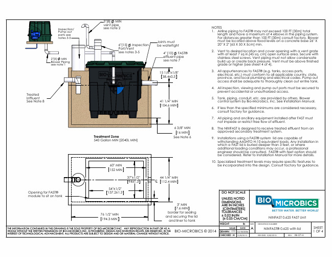
Opening for FAST® module to sit on tank
54"±1/2" 137.2±1.3
76 1/2" MIN 194.3 MIN
3" MIN 7.6 MIN border for sealing and securing the lid and liner to tank
THE INFORMATION CONTAINED IN THIS DRAWING IS THE SOLE PROPERTY OF BIO-MICROBICS INC. ANY REPRODUCTION IN PART OR AS A
WHOLE WITHOUT THE WRITTEN PERMISSION OF BIO-MICROBICS INC. IS PROHIBITED. DESIGN AND INVENTION RIGHTS ARE RESERVED. IN THE BIO-MICROBICS © 2014
6. If less than the specified minimums are considered necessary, consult factory for guidance.
7. All piping and ancillary equipment installed after FAST must not impede or restrict free flow of effluent.
KOHLER Courage XT 发动机说明文档说明书

PERFORMANCE ENGINEERINGOIL FILL VIEWPTO VIEW TOP VIEWK O H L E R ® C O U R A G E ®X T E N G I N E A R C HITECTURE X T-6 a n d X T R -63.8 n e t h p v e r t i c a l -s h a f t e n g i n e sC R A N K S H A F T E X T E N S I O N A I R F I L T E R V I E W X T-6 a n d X T R -63.8 n e t h p v e r t i c a l -s h a f t e n g i n e sXT-6/XTR-61800200022002400260028003000320034003600REVOLUTIONS PER MINUTEK I L O W A T T S NET POWERH O R S E P O W E R1.522.533.544.551.522.533.5Maximum PowerMaximum Torque1800200022002400260028003000320034003600REVOLUTIONS PER MINUTEN E W T O N -M E T E R NET TORQUEF O O T -P O U N D S 44.555.566.577.581010.566.577.588.599.5V A L V E C O V E R V I E WVALVE COVER VIEWAIR FILTER VIEW OIL FILL VIEWK O H L E R ® C O U R A G E ®X T E N G I N EARCHITECTURE X T-7 a n d X T R -74.8 n e t h p v e r t i c a l -s h a f t e n g i n e sP T O V I E W T O P V I E W X T-7 a n d X T R -74.8 n e t h p v e r t i c a l -s h a f t e n g i n e sXT-7/XTR-71800200022002400260028003000320034003600REVOLUTIONS PER MINUTEK I L O W A T T S NET POWERH O R S E P O W E R1.522.533.544.551.522.533.5Maximum PowerMaximum Torque1800200022002400260028003000320034003600REVOLUTIONS PER MINUTEN E W T O N -M E T E R NET TORQUEF O O T -P O U N D S 44.555.566.577.581010.566.577.588.599.5C R A N K S H A F T E X T E N S I O NEngine TypeFour-cycle, single-cylinder, air-cooled, vertical shaft, gasoline, OHV , with cast-iron cylinder bore ModelXT -6XTR-6XT -7XTR-7 Net Peak Torque @ 2800 rpmft lb (Nm) 6.3 (8.5)7.3 (9.9) Max Net Power @ 3600 rpmhp (kW) 3.8 (2.8) 4.8 (3.6) Displacementcu in (cc)9.1 (149)10.6 (173) Borein (mm) 2.6 (65) 2.7 (70) Strokein (mm) 1.8 (45) Compression Ratio9.2:18.5:1 Dry Weightlb (kg)27.5 (12.5)33.5 (15.2)30.5 (13.8)36.5 (16.6) LubricationSplash StartingU.S. qt (L)Recoil Electric Recoil Electric Fuel CapacityU.S. qt (L) 1.2 (1.1) 1.5 (1.4) Oil CapacityU.S. oz (L)20 (.6)*Dimensions L x W x H in (mm)16 x 13.2 x 10.8 (406 x 336 x 274)17.1 x 13.9 x 11 (434 x 353 x 278)KOHLER ® Courage ®XT-Series Model Specifications Information subject to change without notice.Horsepower ratings meet Society of Automotive Engineers Small Engine Test Code J1940. Actual engine horsepower is lower and affected by, but not limited to, accessories (air cleaner, exhaust, charging, cooling), a pplication, engine speed and ambient operating conditions (temperature, humidity and altitude). For more information, contact Kohler Co. Engine Engineering.Kohler reserves the right to change product specifications, designs and equipment without notice and without incurring obligation.*Length is front of blower housing to end of blower housing. Width is air cleaner to muffler guard. Height is mounting surface to grass screen.Standard FeaturesPopular Factory OptionsFor more information, contact your KOHLER source of supply,or call toll-free in the U.S. and Canada 800-544-2444.Kohler Co., Kohler, Wisconsin 53044 Tel 920-457-4441 Fax © 2010 by Kohler Co. All rights reservedPrinted in U.S.A. E-2131-B 10/10KOHLER ®, Courage ®, Accu-Fill ™, Smart-Choke ™ and Consistent-Cut ™ are trademarks of Kohler Co.Relentless Power.Legendary Performance.*Utility engine options•OHV •Cast-iron cylinder bore •Primer bulb •Flywheel ball bearing •Accu-Fill ™ easy-to-fill tank• Easy-pull recoil • Yearly service intervals • Fixed speed • Flywheel brake • Internally vented carburetor • Easy 1⁄4 turn extended dipstick• Panel-type air filter • Recoil start • Muffler with internationally compliant guard • International symbols • Electronic ignition • Internal fuel filter•Smart-Choke ™•Remote manual choke •Blade brake clutch (BBC)•Heavy flywheel*•Engine-mounted controls*• Six-position recoil*• Variable speed • Remote ignition shutdown • Tethered fuel cap • Kill switch • Foam air cleaner*• Side-discharge muffler*• Precleaner • External fuel filter • Energy-saver electric starter • CARB Tier 3 compliance。
Yanmar K21 2.1L 基础 Powershift 1速度 座椅型 1.5 吨 货运车说明书

1 500 -2 000 KGH1.5-2.0XTS DIESEL AND LPG FORKLIFT TRUCKSHYSTERHYSTERH1.5XT H1.5XT Yanmar 2.6L K21 2.1L Basic Powershift Basic Powershift1 speed 1 speed Drum Brakes Drum Brakes DieselLPG/Dual fuel Seated Seated 1.5 1.5 500 500 410 410 1410 1410 2765 2790 2675 2700 3710 545 3680 495 1255 1510 1215 1460 Automatic AutomaticSE SE 6.0-9 6.0-9 21x8-9 21x8-9 5.0-8 5.0-82x 2 2x 2 915 1000 915 1000 905 9056 10 6 10 1995 1995 145 145 3035 3035 4105 4105 2160 2160 970 970 295 295 3200 3200 2280 22801070 1190 1070 1190 35 100 920 35 100 920II II 920 920 110 110 120 120 3565 3565 3365 3365 1960 1960 1845 1845 390 390 24024017.018.0 18.0 19.0 17.018.0 18.0 19.0 0.68 0.71 0.63 0.68 0.500.52 0.50 0.52 17.519.2 36 24 37 24 Hydraulic Hydraulic Yanmar/4TNE92 GCT/K 2129 31 2050 2250143 1400 144 1600 4 2659 4 2065 2.31.52.3 12 9212 55181181 62 59 23.5 23.5 52.0- 81 82 Hook Hook1.1 Manufacturer 1.2 Manufacturer’s type designation Engine / transmissionBrake Type1.3 Drive: electric (battery or mains), diesel, petrol, LPG1.4 Operator type: hand, pedestrian, standing, seated, order-picker 1.5 Rated capacity / rated load Q (t)1.6 Load centre distancec (mm)1.8 Load distance, centre of drive axle to fork x (mm)1.9 Wheelbasey (mm)2.1 Service weight (standard/dual tread) kg 2.2 Axle loading, laden front / rear kg 2.3 Axle loading, unladen front / rearkg8.1 Type of drive unit 3.1 Tyres: L = pneumatic, V = solid, SE = Pneumatic Shape Solid 3.2 Tyre size, front (standard tread)3.2.1 Tyre size, front (dual tread) 3.3 Tyre size, rear3.5 Number of wheels, front/rear (x = driven) 3.6 Tread, front (standard/dual tread) b 10 (mm)3.7 Tread, rearb 11 (mm)4.1 Tilt of mast / fork carriage forward / backward a /b (°)4.2 Height, mast lowered h 1 (mm)4.3 Free lift ¶ h 2 (mm)4.4 Lift ¶ h 3 (mm)4.5 Height, mast extended è h 4 (mm)4.7 Height of overhead guard (cabin) h 6 (mm)4.8 Seat height relating to SIP/stand height ¢ h 7 (mm)4.12 Coupling height h 10 (mm)4.19 Overall length l 1 (mm)4.20 Length to face of forks l 2 (mm)4.21 Overall width b 1/b 2 (mm)4.22 Fork dimensions DIN ISO 2331 s/e/l (mm)4.23 Fork carriage ISO 2328, class/type A, B4.24 Fork carriage width l b 3 (mm)4.31 Ground clearance, laden, below mast m 1 (mm)4.32 Ground clearance, centre of wheelbase m 2 (mm)4.34.1 Aisle width for pallets 1000 × 1200 crossways u A st (mm)4.34.2 Aisle width for pallets 800 × 1200 lengthways u A st (mm)4.35 Turning radius W a (mm)4.41 90° intersecting aisle (with pallet L = 1000mm x W = 1200mm) (mm) 4.42 Step height (from ground to running board) (mm) 4.43 Step height (between intermediate steps and floor) (mm)5.1 Travel speed, laden/unladen km/h 5.1.1 Travel speed, laden/unladen, backwards km/h 5.2 Lift speed, laden/unladen m/s5.3 Lowering speed, laden/unladen m/s 5.5 Drawbar pull, laden kN 5.7 Gradeability, laden/unladen †† %5.10 Service brake D I S T I N G U I S H I N G M A R K SW E I G H T ST Y R E S & C H A S S I S D I M E N S I O N SP E R F O R M A N C E D A T AP E R F O R M A N C E D A T A A D D I T I O N A L D A T AEQUIPMENT AND WEIGHT:Weights (line 2.1) are based on the following specifications: Complete truck with 3035mm TOF 2-stage limited free lift mast, with standard hook type carriage, 920mm forks with manual hydraulics, overhead guard and standard pneumatic shaped solid drive and steer tyres.D R I VE /L IF T M E C H A N I S M7.1 Engine manufacturer/type 7.2 Engine power according to ISO 1585 kW 7.3 Rated speed min–1 7.3.1 Torque at 1/min Nm/min–1 7.4 Number of cylinders/displacement (-)/cm 3 7.5 Fuel consumption according to MIL 268C cycle l/h or kg/h 7.10Battery voltage/nominal capacity S (V)/(Ah) 10.1 Operating pressure for attachments bar 10.2 Oil volume for attachments ³ l/min 10.3 Hydraulic oil tank, capacity l 10.4 Fuel tank, capacity l 10.7 Sound pressure level at the driver’s seat < J dB (A)10.8 Towing coupling, type DINHYSTER HYSTERH1.8XT H1.8XT Yanmar 2.6L K21 2.1L Basic Powershift Basic Powershift1 speed 1 speed Drum Brakes Drum Brakes DieselLPG/Dual fuel Seated Seated 1.75 1.75 500 500 410 410 1410 1410 3000 3000 2920 2920 4090 660 4060 610 1215 1785 1185 1735 Automatic Automatic SE SE 21x8-9 21x8-9 21x8-9 21x8-9 18x7-8 18x7-82x 2 2x 2 915 1000 915 1000 9309306 10 6 10 1995 1995 145 145 3035 3035 4105 4105 2160 2160 970 970 295 295 3240 3240 2320 2320 1135 1190 1135 1190 35 100 920 35 100 920 II II 920 920 110 110 120 120 3605 3605 3405 3405 1995 1995 1895 1895 390 390 240 240 17.0 18.5 18.0 19.517.0 18.5 18.0 19.50.67 0.71 0.62 0.680.50 0.52 0.50 0.5217.4 19.132 22 33 22Hydraulic Hydraulic Yanmar/4TNE92GCT/K 21 29 31 2050 2250143 1400 144 1600 4 2659 4 2065 2.4 1.6 2.4 12 9212 55181 181 62 59 23.5 23.5 52.0- 81 82 Hook Hook 2.12.22.31.11.21.31.41.51.61.81.93.13.23.2.13.33.53.63.75.15.1.15.25.35.55.75.107.17.27.37.3.17.47.57.108.110.110.210.310.410.710.8DISTINGUISHING MARKS WEIGHTS TYRES & CHASSISDIMENSIONS PERFORMANCE DATAPERFORMANCE DATA ADDITIONAL DATANOTE:Specifications are affected by the condition of the vehicle and how it is equipped, as well as the nature and condition of the operating area. Inform your dealer of the nature and condition of the intended operating area when purchasing your Hyster T ruck. ¶ Top of forksè Add 32mm with load backrest ¢ Full suspension seat in depressedpositionl Without load backrest, add 32mm with load backrestuStacking aisle width (lines 4.34 & 4.34.1 & 4.34.2) are based on the VDI standard calculation as shown on illustration. The British Industrial Truck Association recommends the addition of 100 mm to the total clearance (dimension a) for extra operating margin at the rear of the truck††at 4.8km/h. Gradeability figures are provided for comparison of tractive performance, but are not intended to endorse the operation of the vehicle on the stated inclines. Follow instructions in the operating manual regarding operation on inclines.SBattery ampere hour (Ah) nominal capacity ratings are estimated.³ VariableJ L PAZ , Measured according to the testcycles and based on the weighting values contained in EN12053MAST TABLES:v without load backrest s with load backrestDRIVE/LIFT MECHANISMNOTICECare must be exercised when handling elevatedloads. When the carriage and/or load is elevated, truck stability is reduced. It is important that the mast tilt in either direction is kept to a minimum when loads are elevated.Operators must be trained and must read, understand and follow the instructions contained in the Operating Manual.All values are nominal values and they are subject to tolerances. For further information, please contact the manufacturer.Hyster products are subject to change without notice.Lift trucks illustrated may feature optional equipment. Values may vary with alternative configurations.S afety:This truck conforms to the current EU requirements.4.14.24.34.44.54.74.84.124.194.204.214.224.234.244.314.324.34.14.34.24.354.414.424.43EQUIPMENT AND WEIGHT:Weights (line 2.1) are based on the following specifications: Complete truck with 3040mm TOF 2-stage limited free lift mast, with standard hook type carriage, 920mm forks with manual hydraulics, overhead guard and standard pneumatic shaped solid drive and steer tyres.HYSTERHYSTERH2.0XTS H2.0XTS Yanmar 2.6L K21 2.1L Basic Powershift Basic Powershift1 speed 1 speed Drum Brakes Drum Brakes DieselLPG/Dual fuel Seated Seated 2.0 2.0 500 500 415 415 1410 1410 3220 3220 3140 3140 4505 715 4475 665 1210 2010 1180 1960 Automatic AutomaticSE SE 21x8-9 21x8-9 21x8-9 21x8-9 18x7-8 18x7-8 2x 22x 2 915 1000 915 1000 9309306 10 6 101995 1995 150 150 **** **** 4105 4105 2160 2160 970 970 295 295 3275 3275 2355 2355 1035 1190 1035 1190 40 122 920 40 122 920 II II 920 920 110 110 120 120 3640 3640 3440 3440 2030 2030 1920 1920 390 390 240 24017.018.5 18.0 19.5 17.018.5 18.0 19.5 0.660.71 0.62 0.68 0.500.52 0.50 0.52 17.519.2 29 20 30 20 Hydraulic Hydraulic Yanmar/4TNE92 GCT/K 2129 31 2050 2250143 1400 144 1600 4 2659 4 2065 2.51.72.6 12 9212 5518181 62 59 23.5 23.5 52.0- 81 82 Hook Hook1.1 Manufacturer 1.2 Manufacturer’s type designation Engine / transmissionBrake Type1.3 Drive: electric (battery or mains), diesel, petrol, LPG1.4 Operator type: hand, pedestrian, standing, seated, order-picker 1.5 Rated capacity / rated load Q (t)1.6 Load centre distancec (mm)1.8 Load distance, centre of drive axle to fork x (mm)1.9 Wheelbasey (mm)2.1 Service weight (standard/dual tread) kg 2.2 Axle loading, laden front / rear kg 2.3 Axle loading, unladen front / rearkg8.1 Type of drive unit 3.1 Tyres: L = pneumatic, V = solid, SE = Pneumatic Shape Solid 3.2 Tyre size, front (standard tread)3.2.1 Tyre size, front (dual tread) 3.3 Tyre size, rear3.5 Number of wheels, front/rear (x = driven) 3.6 Tread, front (standard/dual tread) b 10 (mm)3.7 Tread, rearb 11 (mm)4.1 Tilt of mast / fork carriage forward / backward a /b (°)4.2 Height, mast lowered h 1 (mm)4.3 Free lift ¶ h 2 (mm)4.4 Lift ¶ h 3 (mm)4.5 Height, mast extended è h 4 (mm)4.7 Height of overhead guard (cabin) h 6 (mm)4.8 Seat height relating to SIP/stand height ¢ h 7 (mm)4.12 Coupling height h 10 (mm)4.19 Overall length l 1 (mm)4.20 Length to face of forks l 2 (mm)4.21 Overall width b 1/b 2 (mm)4.22 Fork dimensions DIN ISO 2331 s/e/l (mm)4.23 Fork carriage ISO 2328, class/type A, B4.24 Fork carriage width l b 3 (mm)4.31 Ground clearance, laden, below mast m 1 (mm)4.32 Ground clearance, centre of wheelbase m 2 (mm)4.34.1 Aisle width for pallets 1000 × 1200 crossways u A st (mm)4.34.2 Aisle width for pallets 800 × 1200 lengthways u A st (mm)4.35 Turning radius W a (mm)4.41 90° intersecting aisle (with pallet L = 1000mm x W = 1200mm) (mm) 4.42 Step height (from ground to running board) (mm) 4.43 Step height (between intermediate steps and floor) (mm)5.1 Travel speed, laden/unladen km/h 5.1.1 Travel speed, laden/unladen, backwards km/h 5.2 Lift speed, laden/unladen m/s 5.3 Lowering speed, laden/unladen m/s 5.5 Drawbar pull, laden kN 5.7 Gradeability, laden/unladen †† %5.10 Service brake D I S T I N G U I S H I N G M A R K SW E I G H T ST Y R E S & C H A S S I S D I M E N S I O N SP E R F O R M A N C E D A T AP E R F O R M A N C E D A T A A D D I T I O N A L D A T AD R I VE /L IF T M E C H A N I S M7.1 Engine manufacturer/type 7.2 Engine power according to ISO 1585 kW 7.3 Rated speed min–1 7.3.1 Torque at 1/min Nm/min–1 7.4 Number of cylinders/displacement (-)/cm 3 7.5 Fuel consumption according to MIL 268C cycle l/h or kg/h 7.10Battery voltage/nominal capacity S (V)/(Ah) 10.1 Operating pressure for attachments bar 10.2 Oil volume for attachments ³ l/min 10.3 Hydraulic oil tank, capacity l 10.4 Fuel tank, capacity l 10.7 Sound pressure level at the driver’s seat < J dB (A)10.8 Towing coupling, type DIN5l l b b b xWa100mm a 2100mma 2Asth h h h sQcαll y l h h h m m βb x40003500300025002000150010005000250500750100012501500H1.5XTH1.8XT H2.0XTS 4000350030002500200015001000500250500750100012501500H1.5XTH1.8XT H2.0XTS RATED CAPACITIESTRUCK DIMENSIONS= Centre of gravity of unladen truck Ast = W a + x + l 6 + a (see lines 4.34.1 & 4.34.2) a = Minimum operating clearance(VDI standard = 200 mm BITA recommendation = 300 mm)l 6= Load lengthLoad centreDistance from front of forks to centre of gravity of load.Rated loadBased on vertical masts up to 3035 mmLoad centre (mm)Standard CarriageIntegral Sideshift CarriageLoad centre (mm)R a t e d l o a d (k g )R a t e d l o a d (k g )2-StageFull Free Lift2-StageFull Free Lift 2-StageLimited Free Lift2-StageLimited Free Lift3-Stage Full Free Lift3-Stage Full Free LiftMaximum fork height (mm)Maximum fork height (mm)MASTMASTWith ISS & FPWith ISS & FPH2.0XT H2.5XT H2.0XT H2.5XT H3.0XT H3.0XTH2.0XT H2.5XT H2.0XT H2.5XT H3.0XT H3.0XTMaximum Fork Height (mm)Maximum Fork Height (mm)Without SideshiftWithout SideshiftWith ISS & FP With ISS & FP Without SideshiftWithout Sideshift3035 1500 1750 1500 1750 3040 2000 2000 3335 1500 1750 1500 1750 3340 2000 2000 3735 1500 1750 1500 1750 3740 2000 2000 4035 1500 1750 1500 1750 4040 2000 2000 4835 1410 1660 1410 1660 4840 1880 1880 3035 1460 1690 1400 1630 3040 1930 1850 3335 1450 1690 1400 1620 3340 1920 1850 4035 1440 1670 1380 1610 4040 1910 1840 4835 1340 1560 1290 1500 4840 1790 1720 5035 1290 1520 1250 1470 5040 1750 1680 4375 1500 1680 1500 1680 4380 1930 1930 4527 1470 1660 1470 1660 4532 1900 1900 4825 1410 1590 1410 1590 4832 1840 1840 5125 1360 1520 1360 1520 5130 1720 1720 6025 1090 1270 1110 1270 6030 1200 12004375 1440 1610 1380 1540 4380 1840 1770 4527 1410 1590 1360 1520 4532 1810 1750 4825 1340 1520 1290 1450 4832 1750 1680 5125 1290 1450 1220 1410 5130 1680 1610 6025 1070 1220 1020 1180 6030 1220 12203025 1500 1750 1500 1750 3030 2000 2000 3325 1500 1750 1500 1750 3330 2000 2000 3025 1450 1680 1390 1620 3030 1920 1850 3325 1450 1680 1390 1610 3330 1910 1840STANDARD FEATURES & OPTIONSSTANDARD EQUIPMENTComplete truck equipped with:n2-Stage limited free lift (LFL) mast with lift height of 3035mm n Hook-type carriage with 1070mm high load backrest (LBR)n920mm long forksn Y anmar 2.6L Diesel or GCT K21 LPG / Dual fueln Powershift Single Speed Transmissionn Directional control levern Single inch / brake pedaln Shift Lever: Left hand on columnn C omfort full suspension seatn Pneumatic shaped solid tyresn 2 cowl mounted hydraulic leversn Standard integrated dash display+ Monochrome LCD panel– Real time clock– Hour meter– Fasten seatbelt– F uel level with low fuel warning buzzer (Diesel fuel only) + Service Indicators– Service required– Coolant temperature with high temp warning buzzer– Alternator with warning buzzer– Transmission oil temperature with warning buzzer– Engine oil pressure with low pressure warning buzzer– Glow lamp (Diesel fuel engine only)– Error messagen Key starting with anti-restart functionn Steering Wheel with Spinner Knobn Synchronous Steeringn Electric Hornn Infinitely adjustable steering columnn Rubber floor matn High air intaken Counterweight exhaustn Black seat beltn Serpentine radiatorn Hyster Stability Mechanism™ (HSM)n Swing down LPG tank bracket (H1.8-2.0XTS)Cabinn O ver Head Guard (OHG) with rain gutter and cup holdern 82 dB(A) standard noise level for LPG/Dual fuelengine optionn 81 dB(A) standard noise level for Diesel engine optionn 12 months / 2000 hours manufacturer’s warrantyn Operator’s manual OPTIONAL EQUIPMENTMastsn 2-Stage limited free lift (LFL) masts with up to 5040mm lift heightn 2-Stage full free lift (FFL) masts with up to 4130mm lift height n 3-Stage full free lift (FFL) masts with up to 6030mm lift heightCarriagesn Integral side shift (ISS) carriageHydraulic Valve and Leversn 3-function cowl mounted hydraulic levers with or without interlock for clampingn 4-function cowl mounted hydraulic levers with or without interlock for clampingForksn Fork lengths are available from 1070mm to 2120mmControlsn M onotrol™ PedalDash Displayn Speedometer with speed alarm and warning buzzern Traction speed limiter (H1.5XT Diesel)n Audible reverse alarmLightsn L ight Kit consisting of: 2 Front Halogen Work Light, Brake / Tail / Back-Up Lights with Turn Signals and reverse alarmn L ED Front Work Lightn L ED Rear Combination Lightn R ear Work Light - Reverse Operatedn R ear Work Light - Switch OperatedEnvironmentaln Vertical exhaustn 2-way catalytic mufflern Spark arrestor mufflern High capacity radiatorn Anti Clog Radiator with Lint Screenn Tilt Cylinder Bootsn High mount pre-cleanerOthern H ydraulic cut-out seat interlock (prevents travel when operator seatbelt is not used)n Lexan Overhead Guard Covern Rear Drive Handle with Horn Buttonn 2 rear vision mirrorswww.hyster.eu*********************/HysterEurope@HysterEurope/HysterEuropeSTRONG PARTNERS. TOUGH TRUCKS.TMFOR DEMANDING OPERATIONS, EVERYWHERE.Hyster supplies a complete range of warehouse equipment, IC and electric counterbalanced trucks, container handlers and reach stackers. Hyster is committed to being much more than a lift truck supplier.Our aim is to offer a complete partnership capable ofresponding to the full spectrum of material handling issues: Whether you need professional consultancy on your fleet management, fully qualified service support, or reliable parts supply, you can depend on Hyster.Our network of highly trained dealers provides expert,responsive local support. They can offer cost-effective finance packages and introduce effectively managed maintenance programmes to ensure that you get the best possible value. Our business is dealing with your material handling needs so you can focus on the success of your business today and in the future.HYSTER-YALE UK LIMITED trading as Hyster Europe. Registered Address: Centennial House, Building 4.5, Frimley Business Park, Frimley, Surrey GU16 7SG, United Kingdom.Registered in England and Wales. Company Registration Number: 02636775. HYSTER,and FORTENS are registered trademarks in the European Union and certain other jurisdictions.MONOTROL ® is a registered trademark, and DURAMATCH and are trademarks in the United States and in certain other jurisdictions.Printed in The Netherlands. Part number: 3990866 Rev. 01-10/17-TLCHYSTER EUROPECentennial House, Frimley Business Park, Frimley, Surrey, GU16 7SG, England.Tel: +44 (0) 1276 538500。
舒驰方桶 (集装桶)

30舒驰回收服务22|23EuropESCHÜTZ (Benelux) B.V.Westelijke randweg 23NL-4791 rT Klundert电话: (+31) 168-334600传真: (+31) 168-334621SCHÜTZ (uK) Ltd.Claylands Av. Dukeries Ind. Est.GB-Worksop, Notts. S81 7BE电话: (+44) 1909-478863传真: (+44) 1909-478864SCHÜTZ France SASChemin du Buisson GayetF-91460 Marcoussis电话: (+33) 1-69805000传真: (+33) 1-64493044SCHÜTZ Iberica S.L.Autovía A7, km 1148.4poligon Camí Mas de ramonES-43480 Vila-seca (Tarragona)电话: (+34) 902-160693传真: (+34) 902-160692SCHÜTZ (Italia) S.r.l.Via San Zenone, 185IT-25020 Dello (BS)电话: (+39) 030-9771611传真: (+39) 030-9771620SCHÜTZ polska Sp. z o.o.ul. post ępu 21 cpL- 02-676 Warszawa电话: (+48) 22-8463405传真: (+48) 22-8680440SCHÜTZ Nordic ASNorvald Strandsvei 131No-2212 Kongsvinger电话: (+47) 62 822750传真: (+47) 62 822751SCHÜTZ (Ireland) Ltd.Killala Business parkTownamoreKillalaCo. MayoIE - Ireland电话: (+353) 96 330 44传真: (+353) 96 330 45ASIA/pACIFIC 舒驰容器(上海)有限公司 普工路100号 上海化学工业区 中国上海201507电话: (+86) 21-6712 0777 传真: (+86) 21-6712 0355 舒驰容器(天津)有限公司 赛达世纪大道11号 天津西青经济开发区 中国天津 300385 电话: (+86) 22-58 33 51 08 传真: (+86) 22-58 33 51 19SCHÜTZ Container Systems Co. Ltd. 5-1-2 Higashi-Yawata Hiratsuka-shi Jp-Kanagawa prefecture 254-0016 电话: (+81) 463-22-8120 传真: (+81) 463-22-6987 SCHÜTZ DSL Group pty Ltd. Corporate office Australia 146 Cockburn road Au-North Coogee WA 6163 电话: (+61) 8 9336 2688 传真: (+61) 8 9430 5031SCHÜTZ DSL (Australia) pty Ltd. 14 Burr Court Au-Laverton North Vic 3026 电话: (+61) 3 9360 9291 传真: (+61) 3 9360 9735SCHÜTZ DSL (Australia) pty Ltd. Building 4 356 Bilsen road Au-Geebung QLD 4034 电话: (+61) 7 3265 4911 传真: (+61) 7 3265 4355SCHÜTZ (Malaysia) Sdn Bhd pT 27773 Jalan Nilam 3 Nilai utama MY-71800 Nilai Negeri Sembilan 电话: (+60) 6 798 0899 传真: (+60) 6 799 3831Clover Chemical Co., Ltd. 80-6, Soosong-Dong Jongno-Gu, Seoul Korea (110-727) 电话: (+82) 2 735 7575 传真: (+82) 2 739 6198AMErICA Headquarters uSA SCHÜTZ Container Systems, INC. 200 Aspen Hill road uS-North Branch, New Jersey 08876 电话: (+1) 908-526-6161 传真: (+1) 908-526-0550SCHÜTZ Container Systems, INC. 2150 Button Gwinnett Drive uS-Doraville, Georgia 30340 电话: (+1) 770-447-5287 传真: (+1) 770-662-8675SCHÜTZ Container Systems, INC. 2105 South Wilkinson Way uS-perrysburg, ohio 43551 电话: (+1) 419-872-2477 传真: (+1) 419-872-9298SCHÜTZ Container Systems, INC. 5000 underwood uS-pasadena, Texas 77507 电话: (+1) 281-474-5200 传真: (+1) 281-474-5240Cardinal Container Services, INC. 138 Walser road uS-Lexington North Carolina 27295 电话: (+1) 336-249-6816 传真: (+1) 336-243-2020SCHÜTZ Container Services plainfield 2375 reeves road uS-plainfield, Indiana 46168 电话: (+1) 317-839-7121 传真: (+1) 317-839-7486SCHÜTZ Container Systems, Inc. 13170 C Marlay Avenue uS-Fontana, California 92337 电话: (+1) 951-360-0260 传真: (+1) 951-360-0489Envases y Laminados, S.A. de C.V. Av. uno No. 12A parque Industrial Cartagena MX-54900 Tultitlan 电话: (+52) 55 5888-0899 传真: (+52) 55 5888-1494Industrias TermoplasticasArgentinas S.A.ruta 5 Km. 75Ar-6706-Jauregui-Buenos Aires电话: (+54) 2323-497-596传真: (+54) 2323-497-844SCHÜTZ VASITEXIndústria de Embalagens Ltda.rua Atecla Fratucelli Lopes, 189Guarulhos – SpBrazil - CEp 07176 - 530电话: (+55) 11-2436-3500传真: (+55) 11-2436-3508AFrICA pArADIGM pACKAGING (pty) Ltd. 6 Edison road Marriann ridge Estate pinetown ZA-3610 Kwa-Zulu Natal 电话: (+27) 31 791 0365 传真: (+27) 31 791 036303.12 | B a u c h & M Ül l e r W e r B e a g e n t u r g M B h | c O r Z I l I u S。
CARBEST 671000 垃圾桶式厕所用户指南说明书

Manuals+— User Manuals Simplified.CARBEST 671000 Cassette Toilet Instruction Manual Home » CARBEST » CARBEST 671000 Cassette Toilet Instruction ManualCassette Toilet671000USER’S INSTRUCTIONContents1 Accessories list2 Installations dimensions3 Main components4 Before use5 Control panel logo & indicator6 Emptying the waste-holdingtank7 Maintenance and cleaning8 Winter use9 Technical specifications10 Installation11 Warranty:12 Documents / Resources13 Related PostsAccessories listInstallations dimensionsPlease read this user manual carefully before you use the product and save it for future reference. Safety instructionsWarning! Risk o f causing serious injury or damage.Caution! Not f o l l o w instruction will lead to damage.This symbol indicates t h a t t h i s operation i s forbidden.This symbol indicates related information.Warning1. A lighted cigarette or other incendiary object must not be put into the toilet or it may cause a fire.2. It is strictly prohibited t o disassemble, repair or modify the product, otherwise it may cause personal injury orfire.3. The product must be connected to DC12V electricity and the positive and negative poles of the electricityshould be properly connected. Otherwise, the product may be damaged or cause a fire.Caution1. The seat and cover of this product have the function of slow down. Do not press hard to avoid damaging thedecelerator.2. When using this product, do not lean back on the cover to avoid damaging the product.3. Do not pour newspaper, paper urinal pad, sanitary towel and the other clogging articles into the toilet.4. Do not stand on the seat, cover or toilet.5. Do not use the toilet below 0 °C. If the indoor temperature i s lower than 0 °C, make sure you completely drainthe waste-holding tank, t o prevent it from expanding and freezing.6. Make sure you cut off the electricity and close the water system of the vehicle during installation, disassemblyand maintenance.7. lf you are not going to use this product for an extended period time, ensure t h a t the power supply is off anddrain the waste-holding tank.8. Children shall not play with t h i s product.Main componentsToilet1. Cover2. Console3. Control panel4. Toilet cover5. Toilet seat6. Swiveling toilet bow!7. B l a d e handle8. Bottom baseWaste-holding tank9. Automatic pressure release vent10. Gasket11. Vent button12. Pull handle4.Screw the cap back onto the tank back into its original position via the service door.Never add toilet cleaner directly via the valve blade or via the toilet bowl as this could damage the gasket ring of the waste- holding tank. Only fill the waste-holding tank via the drain spout.Never use force if you cannot get the waste-holding tank back into place easily. If blockage occurs, always check if the blade handle is in the closed position.Control panel logo & indicatorFlush button: Press and hold it to flush the toilet. Release it to stop flushing.Light off: Indicates the holding tank is not full and it can be used normally.Flashing red light: Indicates the holding tank is full , need to empty it on time.Light off: Indicates the holding tank is in place and the blade handle is in the closed position.Meaning the toilet is closed.Solid green light: The blade handle is in the open position. Meaning the toilet is open.Flashing red light: The holding tank is removed or not in place. Meaning the toilet cannot be used. Toilet Use1. If you want to rotate the bowl to the desired position (max. 90° clockwise and 90° counterclockwise), use bothhands t o rotate the bowl.2. Open the blade by moving the blade hand lever from right to left (Righthand light on the control panel indicatesgreen light).3. Opening the Cover.The toilet can be used with the blade open or closed.The toilet can withstand a maximum load of 125kg. Make sure you do not overload the toilet.Flushing the toilet:1. Make sure the blade is open (Righthand light on the control panel indicates green light).To prevent water leaking damaging your caravan, do not travel with water in the toilet bowl.Close the blade if the toilet is not being used. Do not leave water in the toilet bowl .If you want to continue using your toilet after emptying the waste-holding tank, prepare the waste- holding tank To prevent water leaking damaging your caravan, do not travel with a waste-holding tank that is more than 3/4 full.1. We recommend cleaning the toilet regularly to prevent scale.• Please wipe the dirty are a with a wrung-out soft cloth.Never use household cleaners to clean the toilet. These may cause permanent damage to the gasket and the other components.The blade gasket is apar to f the toilet that is subjected to wear.Depending on the extent and manner of servicing, afte racertain period the gasket will degrade and must be replaced.2. We recommend t o remove the cover regularly to clean the dead corner.• Press the button at the back of cover.• Lift the cover and seat.• Gently push forward to remove the cover.• Installation after removal: Align the cover with the fixed plate and insert it to complete installation. Winter use1. The toilet seat can be used even in cold weather as long as it is placed in a heated area.2. lf there is no heating and there is a risk of frost, we recommend against using the toilet.If the indoor temperature is lower than 0 °C, be sure to complete the drain of the toilet and RV water system.Then empty the waste-holding tank, t o prevent i t from expanding and freezing .When this product is left unused1. Empty the water system of the vehicle.2. Press and hold the flush button of the toilet until no water rushes o u t .3. Empty and dry the waste-holding tank.4. Rinse and dry the entire toilet thoroughly.5. Slide the waste-holding tank back into its original position and close the blade.Technical specificationsModel671000Direction D W HDimensions (mm)*577355538Net weight (kg)9.8 (including the service door )Capacity waste-holding1 7 . 2tank {L}Installation1. Install the service door (Use Carbest service door).• Create the wall cut-out for the service door. Use the template with drawings a s the correct reference for the cut-out dimensions ( The wall thickness needs to be between 23mm and 39mm for the service door}.• Install the service door. For further information, see the installation instructions o f the service door.2. Make sure that the toilet dimensions below, fit t o the shower tray before installation3. Mount the wall bracket to the outside wall with three screws ST4.2*13mm, connecting the toilet to the wallbracket.Recommended distance between the wall bracket screws and the installation floor: 518mm (The actual installation may need t o adjust the position appropriately).4. Mount the toilet to the floor with four screws ST4.5*55mm.Required torque (for a plywood oor): 1.2+0.3N.m.Torque may differ if the floor is made from a different material.5. Connecting the water hose to the water system of the car.Length from the last fixed point: 300mmDiameter Inside: 10mm Outside: 16.5 mmRequired presure Min.:0.35bar at4.2L/min Max.:0.70bar at 7.1L/minMaximum allowable pressure8barMake sure after the hose is connected, the waste-holding tank can still be pulled out of the toilet seat and removed.6. Adjust flush pressure (if applicable ) . Meet the required pressure for the remote pump at the toilet inlet toensure correct flush. If the pressure is too high, use a slotted screwdriver to adjust the “water pressure control”knob on the solenoid valve.Connecting electricity1. Length o f main cord is 120mm.cause a fire.Connector 4 terminal blocksPosition wiringCable connections when the toilet is connectedto a pressure systemThe red cable is positive. The black cable is negative .Cable connections when the toilet is connectedto a non – pres – suresystemThe red cable is positive. The black cable is negative. The brown cable is positive. Connect the blue cable to the positive connection of the pump.The power supply specifications: 12V DC.Install the vent hose & flangeAt the desired location, drill 09mm diameter hole together with the vent joint on the ground and connect vent hose with two screws ST4.2*13mm .MalfunctionsPossible reasonsSolutionsUnable to pull out the wast e- holding tank1. Blade (partially) not closed2.Due to the clip of waste-holding tank not lifted1. Fully close the blade2. Lift the clip, then pull outPress the flush button but no flush-water1. When the waste-holding tank is full, t he left light on the control panel blinks r ed2. When the waste-holding tank is remo ved or not in place, the right light on the control panel blinks red3. When the blade is closed, the light on the control panel is off4. When the light on the control panel is off, indicates the toilet fuse is blown out1. Empty the waste-holding tank2. Slide the waste-holding tank back in place3. Move the blade handle to open the bl ade4. Replace the toilet fuseWaste-holding tank leaking Gasket is dry or worn out Replace gasketIn order to flush the valve, please turn the valve handle to make it open. After using, please turn the valvehandle to close the valve. Do not use the toilet when the red light is flashing.If you cannot solve the problem, contact the authorized local service center or REIMO Customer Ser-vice Office in your country.Warranty:The warranty period is 36 months. Reimo reserves the right to rectify eventual defaults. The guarantee is excluded for all damages caused by faulty use or improper handling. Liability limitations:In no case Reimo will be reliable for collateral-, secondary- or indirect damages, costs, expenditure, missed benefits or missed earnings. The indicated sales price of the product is representing the equivalent value of Reimo’s liability limitations.REIMO REISEMOBIL-CENTER GMBH63329 EGELSBACH • BOSCHRING 10GERMANY • MADE IN CHINA • © 02/2022Documents / ResourcesCARBEST 671000 Cassette Toilet [pdf] Instruction Manual671000 Cassette Toilet, 671000, Cassette Toilet, Toilet Manuals+,。
SIRMAN PP4 PP8 说明书
意大利舒文牌SIRMAN 去马铃薯皮机PP4PP8操作和维修保养手册序言·本指导手册给使用者提供了所有有关设备的必要信息、应用的生产标准和操作指引,令使用者能够使设备保持好的效率。
·本指导手册是提供给最终用户和技术服务人员的。
目录第一章设备概述41.1 一般防护措施1.2 设备的安全装置1.3 设备概述1.3.1 一般概述1.3.2 结构特征1.3.3 零部件第二章技术数据52.1 整机尺寸、重量、特征第三章验收设备63.1 设备运输3.2 包装检查3.3 包装物弃置第四章安装74.1 选择安装地点4.2 电路连接4.2.1 单相电机电路连接4.2.2 三相电机电路连接4.3 接线图4.3.1 单相接线图4.3.2 三相接线图4.4 检测开关功能第五章操作105.1 控制开关5.2 放食物第六章日常清洁106.1 概述第七章维修保养117.1 概述7.2 皮带7.3 支脚7.4 电源线第八章设备弃置118.1 确定丢弃82 弃置插图索引图1——整机结构5图2——整机尺寸6图3——包装说明7图4——排水管连接图7图5——铭牌8图6——单相接线图8图7——三相接线图9图8——旋盘转动方向9图9——控制开关10 图10 ——放食物10 图11 ——清空食物10第一章设备概述1.1 一般防护措施·PP(包括PP4、PP8)/LC/PC系列设备必须只能由熟知本手册中提及的指引和安全标准的人员操作。
·如果有操作人员调动,需要对新的操作人员进行操作前培训。
·虽然设备装上了安全装置,但也要尽量避免用手(包括湿的手)直接接触或移动设备及其零部件。
·在进行清洁或维护前,必须切断电源。
·当进行清洁或维护时(安全装置被移开),必须考虑到余下的可能发生的风险。
·当进行清洁或维护时,操作人员必须高度集中注意力,以避免分心。
·定期检查电线,避免电线打结;磨损的电线会导致严重的触电危险;避免用重物压住电线或把电线放置在热的或锋利的表面;避免直接拉电线,把插头从插座中拔出。
KARCHER PC 60 115 T 说明书

在初次使用您的设备之前,请阅读并遵守这些说明。
将这些使用说明保存好以备未来作为参考或留给后来的使用者。
运输中出现损坏,立即通知销售人员。
正确的使用 1 功能 1 安全说明 1 安全设备 2 设备元件 3 启动 4 使用 4 停止 5 维护和保养 6 故障检修 7 保修 8 技术规格 8 CE 声明 8 设备被设计用水溶液来自动清洗金属加工业的零件。
--设备只能使用含水的洗涤剂。
--不要加注溶剂,易燃或易爆的液体。
--只可以使用在凯驰商品目录里列出的液体洗涤剂,和被用来清洗零件的洗涤剂。
在水容器里的液体洗涤剂通过加热元件在设定的温度下加热,然后通过泵运输到三个喷嘴件里。
把将被清洗的零件放置在电驱动的旋转桌上,零件绕着喷嘴件架旋转。
这样可以确保适当地清洗零件的所有面。
清洗时间结束后或手动复位后,泵和电旋转驱动设施会自动关闭。
现在可以将清洗好的零件取下来了。
内置的油水分离器是用来把油和洗涤剂液体分开的。
在清洗过程中,沾上油的零件会与洗涤剂接触。
为了确保最佳的清洗功能,油水分离器只能在清洗过程的间隔期启动操作。
--请在使用设备前阅读使用说明,特别注意以下的安全说明。
--在设备上的警告和信息板为安全操作提供了重要的指导。
--除了在使用说明里包含的信息,还必须遵守所有法定的安全和事故防范条例。
--铭牌上显示的电压必须与电源电压一致。
--安全等级I 的设备只能被连接到有适当接地保护的插座上。
--建议您将设备连接到带有一个30毫安逆电流保护开关的插座上,这个保护开关可以防止接错电流。
--请使用厂商规定的电源电缆。
当更换电缆时也可以使用相同的电缆。
对于具体型号参见电路图。
--操作会导致短期电网波动。
在不利的电网条件下,其他的设备可能会被干扰。
当电网阻抗低于0.15欧姆时,不会有干扰。
--决不要用湿手接触电源插头。
--确信电源线或延长电缆不会被碾坏,夹坏,拉坏等类似的行为而损坏。
保护电缆防止受热,沾油和碰触尖锐的边缘。
低压排液桶操作规程(3篇)
低压排液桶操作规程低压排液桶是常用于化工、制药、食品等行业中,用来储存和排放废液或剩余液体的装置。
为了保障操作安全和环境卫生,必须严格遵守低压排液桶的操作规程。
以下是低压排液桶的操作规程,详细介绍了操作过程中的注意事项和操作步骤。
一、准备工作1.1 检查低压排液桶的安全阀、进气阀和排液阀是否正常,并确保无堵塞。
1.2 检查低压排液桶周围是否有易燃、易爆和腐蚀性物质,清理好工作环境。
1.3 穿戴好防护服、手套、防护眼镜等个人防护装备。
二、操作步骤2.1 打开进气阀,将空气通过进气阀注入低压排液桶,确保低压排液桶内部压力与外部一致。
2.2 缓慢打开排液阀,使废液或剩余液体流入预先准备好的容器中。
2.3 注意观察液体的流动情况,如发现液体流动不畅或存在异常情况,应立即停止操作,并排查原因。
2.4 排液完成后,关闭排液阀和进气阀,断开低压排液桶与容器之间的连接。
三、安全措施3.1 操作人员在进行低压排液桶操作时,应保持警觉,严禁随意打闹或分散注意力。
3.2 操作人员在操作过程中不得驻足、站立或坐在低压排液桶上,以免发生意外。
3.3 在操作结束后,应将低压排液桶内的残液清理干净,并将周围环境整理整洁,防止滑倒和其他意外发生。
3.4 操作人员在进行低压排液桶操作时,应定期接受安全培训,了解低压排液桶的特点和操作规程,提高安全意识。
四、应急处理4.1 在操作过程中如发生泄漏或溢出现象,应立即停止操作,采取相应的应急处理措施,包括使用合适的吸油材料进行吸附、封闭泄漏源等。
4.2 如发生火灾或其他意外事故,应立即报警并采取安全疏散措施,保护自己和周围人员的生命安全。
五、操作记录5.1 操作人员在进行低压排液桶操作过程中应准确记录操作时间、操作量、操作人员和操作情况等相关信息。
5.2 操作记录应及时归档和备份,便于日后查阅和追溯。
六、定期检查6.1 定期对低压排液桶进行检查,包括安全阀、进气阀和排液阀的压力是否正常,有无损坏或漏气现象。
低压排液桶操作规程范文
低压排液桶操作规程范文第一章总则第一条为了确保低压排液桶的安全使用,保护人身安全和财产安全,制定本操作规程。
第二条本操作规程适用于所有使用低压排液桶的人员,包括操作人员、维护人员和管理人员。
第三条本操作规程的内容包括低压排液桶的基本概念、操作要求、安全注意事项、维护保养等方面的规定。
第四条所有使用低压排液桶的人员都必须熟悉本操作规程,并按照规程执行。
第二章低压排液桶的基本概念第五条低压排液桶是一种用于排液的装置,由容器、排液管、阀门等部分组成。
第六条低压排液桶的容器通常采用耐腐蚀材料制成,具有一定的韧性和强度,能够承受一定的压力。
第七条低压排液桶的排液管连接在容器的底部,通过阀门控制排液的流量。
第三章低压排液桶的操作要求第八条在操作低压排液桶之前,必须对装置进行检查,确保其正常工作。
第九条检查低压排液桶的容器是否存在漏损、变形、腐蚀等问题,如发现异常情况,应及时进行维修或更换。
第十条检查低压排液桶的排液管是否通畅,阀门是否灵活,如有问题,应及时清理和维修。
第十一条操作低压排液桶时,应注意与其他设备、管线的安全距离,避免碰撞和破坏。
第十二条在操作低压排液桶时,必须穿戴好相应的个人防护装备,包括防护服、防护眼镜、防护手套等。
第十三条操作人员应严格按照操作规程进行操作,不得擅自更改操作方法和操作流程。
第十四条在操作低压排液桶时,应确保容器内部无压力,采取相应的排液措施,确保安全。
第四章低压排液桶的安全注意事项第十五条在操作低压排液桶时,严禁烟火、明火等火源。
第十六条在操作低压排液桶时,严禁随意拧动阀门、排液管等部件。
第十七条在操作低压排液桶时,应保持容器周围的通风畅通,避免积聚有毒有害气体。
第十八条在操作低压排液桶时,应注意防止溅泼和滴漏,必要时可采取防护措施。
第十九条在操作低压排液桶时,如遇到突发情况,操作人员应立即采取相应的应急措施。
第二十条在操作低压排液桶时,如发现异常情况,应立即停止操作,并上报有关部门。
Roval 回收槽式纸巾座和垃圾桶说明书
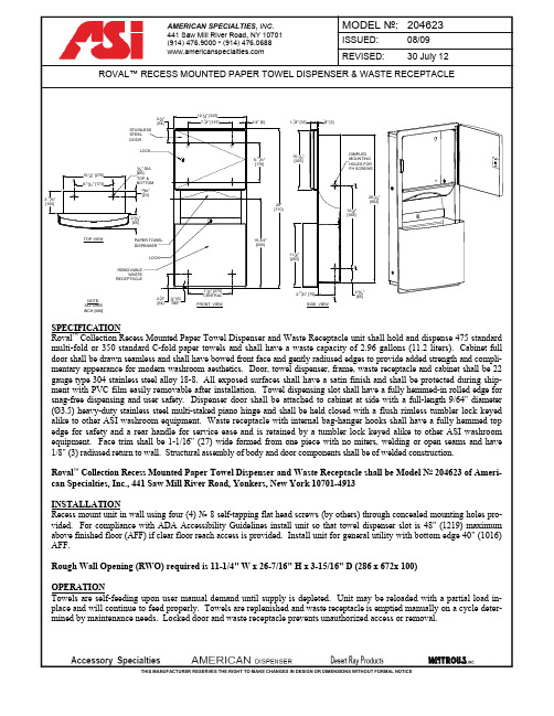
THIS MANUFACTURER RESERVES THE RIGHT TO MAKE CHANGES IN DESIGN OR DIMENSIONS WITHOUT FORMAL NOTICE1-7/32" [31]1-17/32"[39]7-9/32"[185]2-13/32"3-15/16"[100]29/32"[23]C LC L C LC LSURFACE MOUNTED SENSOR HAND DRYER WITH CAST IRON COVER (Pg 1 of 2)SURFACE MOUNTED SENSOR HAND DRYER WITH CAST IRON COVER (Pg 2 of 2) MODEL TYPE0195HandMODEL MOTOR H/P x10000195Brush Type Dual Ball .25RECESS MOUNTED STAINLESS STEEL HORIZONTAL BABY CHANGING STATION (Pg 1 of 2) SAFETYINSTRUCTIONSOPTIONALMOUNTING HOLESWITH PLUG COVERSRECESS MOUNTED STAINLESS STEEL HORIZONTAL BABY CHANGING STATION (Pg 2 of 2) INSTALLATIONInstallation instructions along with operation and maintenance manual are provided with each unit. Unit is recess mounted using hardware supplied through concealed mounting holes. Hardware kit supplied has fasteners suitable for metal or wood stud walls in dry locations and general hollow wall construction where adequate substrate strength is obtained. Fasteners and anchors for masonry walls are not provided. Wall reinforcement must be suitable to sustain transfer of maximum unit loading. Mounting hole plug covers are supplied to conceal fasteners after installation. Provide rough wall opening (RWO) of required depth from face of finished wall. Mount unit in properly framed RWO using four (4) № 10holes mounting see installation instructions packed with unit. Alternateframing reinforcement permits is to use four (4) 3/8wall conditions, not supplied) through mounting holes in rear wall of cabinet. Use washers and mounting hole plug covers provided.Rough Wall Opening (RWO) required is 35SURFACE MOUNTED SENSOR HAND DRYER (Pg 1 of 2)31/32"REFC L8-13/16"[224]C LSURFACE MOUNTED SENSOR HAND DRYER (Pg 2 of 2) MODEL TYPE0165HandMODEL MOTORTHIS MANUFACTURER RESERVES THE RIGHT TO MAKE CHANGES IN DESIGN OR DIMENSIONS WITHOUT FORMAL NOTICETHIS MANUFACTURER RESERVES THE RIGHT TO MAKE CHANGES IN DESIGN OR DIMENSIONS WITHOUT FORMAL NOTICESURFACE MOUNTED JUMBO10-5/8" [270]# 16 GAUGESTEEL WITH FIXED SPINDLETHIS MANUFACTURER RESERVES THE RIGHT TO MAKE CHANGES IN DESIGN OR DIMENSIONS WITHOUT FORMAL NOTICETURBO -TUFF 12-27/32"14-3/16"[376]7/8" DIA [Ø22]ELEC KO TYP 5 LOC'SC LC LNOTE:ALL DIM ’S INCH [MM]ILLUSTRATION FOR REF ONLY AND NTS FOR CLEANING INSTRUCTIONS SEE APPROPRIATE SECTIONS IN PRODUCT CARE & MAINTENANCEBULLETIN (PCM) ON ASI WEBSITE CSA = CONCEALED SCREW AXISTURBO-TUFFINSTALLATIONMount unit cabinet in wall recess with four (4)(by others) or other suitableexpansion bolts or anchors for 1/4" (M6) screws. See unit diagram for electrical service cable roughElectric service of 100-location for dryer indicated on diagram above and is hooked up (by others) in accordance with schematic and OM provided with unit. Electrical service is supplied and connected (by others) prior to installing cover. Cover is secured to cabinet with two (2) hex socket captive truss flange head screws (supplied). For compliance with ICC/ ANSI A-117.1 and 2010 ADA Accessibility Standards, install unitmax AFF (Above Finished Floor) if clear floor forward or side reach access is provided or 46" [1168] max AFF if side reach access over an obstruction (e.g. vanity) with reach depth greater than 10" [254] and less than 25" [635] is only provided or 44" [1118] max AFF if forward reach over an obstruction (e.g. commode) with reach depth greater than 20" [508] and less than 25" [635] is only provided. For general utility, install unit so that top of dryer hand chamber is 44" toinstallation of two or more dryers, dryers should be no closer than 24" [610] on center. See OM and Template MT。
低压排液桶操作规程
行业资料:________ 低压排液桶操作规程单位:______________________部门:______________________日期:______年_____月_____日第1 页共6 页低压排液桶操作规程1、将液位总调节站上的直接供液和蛇形管供液关闭,开启3.5㎡排液总阀(进入系统的液氨也是通过此阀)。
2、再关排液桶的抽气阀,冲霜吐液阀,吸气管吐液阀,缓慢开启热氨加压阀,桶内压力达到(不得超过)0.6Mpa时,关闭热氨加压阀。
3、打开加油阀,向集油器放油,当放油管温度下降时,应关闭放油阀,停止放油工作。
4、开启排液阀向低压循环桶送液,待听到排液管有气流声时,说明液体已排完。
5、待容器内压力降至0.1Mpa左右时,关闭排液阀。
6、打开抽气阀,吐液阀,液位总调节站3.5㎡排液总阀,恢复该桶正常待用工作状态。
7、3.5㎡排液桶内液面不得超过80%,正常情况下,应为先冲霜,后排液,特殊情况,可边冲边排。
8、排液桶一般情况下应桶内无积油,保持空桶待用状态。
9、桶内压力高于低压系统压力时,操作人员不得离开现场。
10、排液桶上安全阀的控制阀、压力表阀均应常开。
低压接地故障与电气火灾电气火灾在火灾事故中占有很大比例,仅次于一般由火引起的火灾。
而电气火灾中有相当一部分是由接地故障引起的。
本文就几种低压第 2 页共 6 页接地保护方式的防火安全程度作一探讨。
低压接地故障是指相线对地及与地有联系的导体之间的短路,包括相线与大地、PE线、PEN线、设备金属外壳、金属管道及金属构件等之间的短路,针对低压接地故障而采取的保护措施为接地故障保护,即把在故障情况下可能呈现危险的对地电压的金属部分同大地紧密地连接起来,从而降低对地的危险电压;提供低阻抗电流通路,以便线路保护装置可靠动作、切断故障回路,。
低压接地故障保护的方式在TN-C、TN-S、TT、IT几种接地形式不尽相同。
1、TN-C系统:此系统中PE线与N线合二为一,是过去广泛采用的接零保护方式。
卡特(Cat)桶(Bucket)说明文件说明书

High Performance• Productivity is at its best when you pair your Cat machine witha Cat bucket, which we purpose-design to optimize the breakout force and power of the machine.• The dual radius shell profile improves material flow into the bucket. The added heel clearance ensures the bottom of the bucket does not drag, reducing maintenance costs.• Fuel consumption peaks during digging. Cat buckets are designed to cut through material quickly to enhance your machine’s overall operating efficiency.• Load more material in less time. Bucket shape and sidebars keep the most material in your bucket for every load.Reliability and Durability• Count on the structural integrity of your bucket long-term.The integrated hinge plate helps distribute force better thana weld-on hinge plate.• Cat buckets are manufactured with high-strength, abrasion-resistant steel, especially in excessive wear areas.• Protect the high wear areas of your bucket coming into contact with materials the most with Cat Ground Engaging Tools (GET).• Get higher production in demanding applications, easier penetration into piles, and faster cycle times with Cat Advansys™ GET.• Install and remove tips faster than ever with the Advansys hammerless GET system.• Ensure a secure fit for tips and adapters, using only basic hand tools, with CapSure retention.• Reduce maintenance costs by selecting the right GET for your bucket and application combination. Bucket tips are availablein a variety of options to suit your specific application needs.Versatility and Convenience with Couplers• Managing multiple buckets and other attachments for a fleet is easier with a coupler system. Couplers allow machines of similar sizes to share and attachments can be changed out in seconds without leaving the safety of the cab.• Buckets capable of being pinned directly to the machine are also compatible with Cat Pin Grabber Couplers, except Pin Grabber Performance buckets. Pin Grabber Performance buckets have a recessed pin which optimizes breakout force resulting in faster cycle times for your bucket when using with a Cat Pin Grabber Coupler.• The Cat Pin Grabber Coupler also gives the operator the ability to pick up a bucket in reverse position to clean out and square corners with ease.• Ensure your attachments are secure with audible and visible cues from the coupler’s secondary latch, always in the operator’s lineof sight.• Cat Pin Grabber Couplers are compatible with 311-352 tracked excavators and all wheeled excavators. Trenching width couplers are also available.• Attachments compatible with the CW Dedicated Coupler system use fixed quick coupler hinges. CW Dedicated Couplers feature a wedge-style locking system to keep attachments secure.• CW Dedicated Couplers are available for all tracked and wheeled excavators.Cat® buckets are more than just an add-on, they are an extension of your Cat machines. Each one is perfectly balanced to our excavators so you can take on heaping loads without compromising fuel efficiency or machine health. We built them to fill faster, retain your load, and fit your task.Not all attachments are available in all regions. Consult your Cat dealer for specific attachments available in your region.Cat®Heavy Duty Excavator BucketsHeavy Duty – All-Around Digging Solution• For situations where your application conditions may change, Heavy Duty buckets are the most practical choice for your operation, with widths ranging from 450-2150 mm (18-85 in). Their versatility across application types makes them the most popular excavator bucket choice where tip life ranges from 400 to 800 hours.• Heavy Duty buckets work best in a wide range of impact and abrasion conditions including mixed dirt, clay, and rock.• Wear plates across the bottom of Heavy Duty buckets rangeup to 20-40 percent thicker than on General Duty buckets.• Side wear plates are up to 17-25 percent thicker than their General Duty counterparts.• Heavy Duty buckets for medium to large excavators can expectup to 14-17 percent increase in Side Bar thickness.• Balance power and efficiency with Heavy Duty Power buckets, Power buckets are best in applications where breakout forceand cycle times are critical.• Dig deeper into rock-type materials with a spade edge. The spade edge helps dig further into these bulky materials and guide them into the bucket.• You can pin Heavy Duty buckets directly to the machine or use them with a Cat Pin Grabber Coupler or CW Dedicated Coupler.Boost Efficiency and Productivity with Integrated Cat Connect Technologies• Never waste time looking for your buckets again. Cat asset tracking is available on select buckets.• Track your entire fleet of attachments and machines from one source. Buckets with asset tracking can be viewed within VisionLink® alongside Product Link™ subscribed equipment.• Keep your assets secure. Buckets with an asset tracker send an alert if they leave an easy-to-setup site boundary.Cat® Heavy Duty Excavator Buckets。
Philips AIB2207 93, AIB2208 93智能坐便盖使用说明书

智能马桶智能坐便盖AIB2207/93 AIB2208/93199用户必读安全注意事项安装前准备事项装箱清单安装步骤主要技术规格SIAA 抗菌认证说明遥控器操作界面使用方法维护保养长时间不使用处理故障诊断环保清单能效水效等级保修卡名称主机遥控器过滤器固定板调节压板/调节片进水软管膨胀螺钉组使用说明书(含保修卡)配网指南合格证数量备注1台1个1组7号电池2个已安装,置于主机底部1个2组1根2组1本1张1张说明:①本产品在环境温度23℃,进水静压0.2MPa ,进水温度15℃条件下,将水压、水温、座温设置为最高档, 记录从按下妇洗按键到妇洗停止喷水,一个清洗周期的平均功率;②最大输入功率:本产品在环境温度23℃,进水静压0.2MPa ,进水温度5℃条件下,依次将流量调到最大, 座温 、水温设置为最高档位后,立即开启妇洗并完整工作一个清洗周期的平均功率;③最佳清洁性能说明:本产品获得最大清洁率效果,需将水压、水温调到最高档后,开启臀洗功能,调整喷 头位置到最前端,清洗1分钟后,调整喷嘴位置到最后端,直至清洗周期结束;④SIAA 抗菌认证说明:产品座圈和喷嘴材质经过SIAA 抗菌协会认证的,能够有效抑制大肠杆菌、金黄色葡萄 糖球菌繁殖,抗菌率99.9%。
名称热水水温加热器功率表面温度加热器功率座圈材质暖风温度风速暖风功率加热座圈暖风尺寸型号智能坐便盖AIB2207/93AIB2208/93常温~41℃约1600W 室温~41℃约45W SIAA 认证抗菌PP常温~55℃≥4m/s 200W 518*470*121mm WIFI核准代码CMIIT ID:2020DP6290执行标准GB 4706.1-2005 GB 4706.53-2008 GB 38448-2019自动/停止臀洗水压调节 “+”水压调节 “-”妇洗暖风座温按摩用户B夜灯喷嘴位置“前移”喷嘴位置“后移”水温风温用户A喷嘴自洁喷嘴自洁+按摩=开启/关闭久坐提醒喷嘴自洁+用户A =配网联网喷嘴自洁+用户B =解绑联网长按座温开启座温节电,离座后温度降至28℃长按开启待机长按水温开启喷嘴自洁(按停止键关闭自洁)自动/停止臀洗水压调节 “+”水压调节 “-”妇洗暖风座温按摩用户B夜灯喷嘴位置“前移”喷嘴位置“后移”水温风温用户A爱恩净爱恩净+按摩=开启/关闭久坐提醒爱恩净+用户A =配网联网爱恩净+用户B =解绑联网长按座温开启座温节电,离座后温度降至28℃长按开启待机3.暖风4分钟或离座后自动停止,或按“ ”键停止。
煮面桶的使用操作方法
煮面桶的使用操作方法
作为一款方便快捷的食品,煮面桶在现代生活中越来越受到欢迎。
但是对于初次使用煮面桶的人来说,可能不太清楚该如何使用。
下面就为大家详细介绍一下煮面桶的使用操作方法。
一、准备工作
我们需要准备一些必要的材料和工具,例如:煮面桶、开水、调味料、叉子、碗、筷子等。
确保这些准备工作完成后,我们才能开始进行下一步操作。
二、煮面
1.打开煮面桶的盖子,取出里面的面条和调味包。
2.将面条放入煮面桶中,然后倒入适量的开水。
一般来说,开水的量要比面条稍微高一些。
3.盖上煮面桶的盖子,等待大约3-5分钟,这个时间也可以根据个人口感来进行调整。
4.等待过程中,我们可以将调味包的内容倒入碗中,然后加入适量的开水搅拌均匀,这样调味料就可以充分溶解。
5.3-5分钟后,打开煮面桶的盖子,用叉子将面条取出,放入碗中。
三、调味
在将面条放入碗中后,我们需要将调味料倒入碗中,搅拌均匀即可。
如果需要添加一些蔬菜或者肉类等食材,可以提前准备好,加入到碗中,一起搅拌均匀。
四、享用美食
我们就可以使用筷子将面条夹起来,放入嘴里享用美食了。
如果觉得面条的口感不够好,可以根据个人口味添加一些辣椒油或者醋等调味品。
总结来说,煮面桶的使用方法非常简单,只需要准备好必要的材料和工具,按照以上步骤操作即可。
但是在使用过程中,也需要注意一些细节,例如:开水的温度和量要适当,面条的时间要掌握好等等。
只有这样,才能制作出一份美味可口的煮面桶。
养生桶的操作方法

养生桶的操作方法养生桶是一种新兴的健康养生工具,可以在家中享受到全身的养生理疗。
下面将详细介绍养生桶的操作方法。
首先,为了使用养生桶,我们需要将其放置在一个稳定的地方,最好是在浴室或者阳台等具备排水设施的地方。
确保养生桶周围没有堆积物,以免发生意外。
接下来,我们需要将养生桶的底部连接到水源。
一般来说,养生桶会配备一个配水管或者水龙头接头,可以很方便地与水源连接。
确保连接紧密,没有渗漏。
在连接好水源后,我们需要按照养生桶的说明书来调整合适的水温。
一般来说,养生桶的水温可以调节在37-42摄氏度之间,根据个人的喜好和体质情况来设定。
然后,我们可以将养生桶填满水。
为了达到更好的养生效果,可以在水中加入一些草药等养生成分,比如玫瑰花瓣、茉莉花等。
这些草药可以让养生浴的效果更好,同时也带来放松身心的愉悦感。
在水温和水量调节好后,我们可以开始享受养生浴了。
首先,先将养生桶的盖子打开,然后慢慢地进入养生桶内。
由于养生桶的大小比较有限,所以可以采取半蹲姿势或者坐在养生桶内。
根据个人喜好,也可以选择搭配一把独立的凳子以增加舒适度。
当身体完全浸泡在养生桶内后,可以选择按摩功能来放松身心。
养生桶一般会提供冲击波按摩、水流按摩等功能,根据个人需要来选择合适的按摩方式。
同时,在按摩过程中可以选择合适的水压和水量来达到最佳的舒适感。
除了按摩功能,养生桶还可提供浴液疗法功能。
在养生桶中加入适量的浴液后,可以按照养生桶的说明书进行设置,让养生桶以特定的方式释放浴液。
这样,可以通过吸入浴液的方式来进行养生浴,达到更好的养生效果。
在养生浴结束后,需要将养生桶内的水排出。
一般来说,养生桶会有排水管或者底部排水孔,可以通过旋转或拉动来控制水的排出。
确保排水充分,以免残留的水影响养生桶的清洁和使用。
最后,我们需要对养生桶进行清洗和保养。
每次使用后,可以用清水冲洗养生桶的内部和外部,并用柔软的布擦拭干净。
定期清洗过滤网和喷嘴,以保证养生桶的正常使用和卫生。
4737新版用户手册-T01-C

17
Toubleshooting
17
Service Parts
21
1119101-T01-C
2
Kohler Co.
IMPORTANT SAFEGUARDS
SAVE THESE INSTRUCTIONS
WARNING: Risk of electric shock, fire, or personal injury. This product must be grounded. Connect only to a dedicated 220~240V AC, 50/60Hz, 10A circuit protected by Ground-Fault Circuit-Interrupter (GFCI) or Earth-Leakage Circuit-Breaker (ELCB).
Never drop or insert any objects into any opening or hose.
Do not use outdoors or where aerosol spray products are being used or where oxygen is administered.
English page 1~24 中文页码 25~43 1119101-T01-C
Contents
IMPORTANT SAFEGUARDS
3
Function List
5
Specifications
6
Thank You For Choosing Kohler Company
7
Keypad and Panel Diagram
Never operate this appliance if it has a damaged cord or plug, if it is not working properly, if it has been dropped, damaged, or dropped into water.
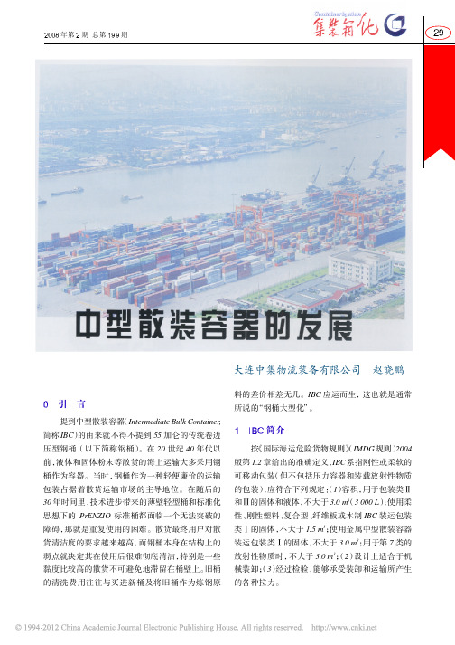
中型散装容器的发展
的重点,关系到产品成本和性价比,下面进行详细 × = 10 000
0
是在拉应力下的标准钢的最低伸张度) 则金属 , 表1 采用标准钢的金属 IBC 的最小壁厚
壁厚 型 无保护 有保护 1.5 无保护 2.5 有保护 2.0 T=C/2000 + 1.5 型
IBC 的壁厚不应小于表 1 所示。
容量
的两种产品, 相信这两种产品在市场上势均力敌的 情况还会持续很长时间。目前, 我国国内的散货生 产者出于成本的考虑仍然在大量使用一次性包装 和 55 加仑钢桶, 造成很大的资源浪费和环境污染。 部分在华的外商合资企业沿用其在国外的生产方 式, 愿意使用 IBC 作为散货物流容器。作为 IBC 行 业的从业人员, 这种现状是笔者不愿看到的。经济 要快速发展, 但不能以环境污染为代价。我国政府 对经济的可持续发展和环境保护越来越重视, 这对 于 IBC 这种环保的物流产品肯定是一个机遇。 相信 在不远的将来, 也会占据我国容积在 3 m3 以下 IBC 的中小容量物流产品的大部分市场份额。
简介
按 《国际海运危险货物规则》 (IMDG 规则) 2004 版第 1.2 章给出的准确定义, 系指刚性或柔软的 IBC 可移动包装 (但不包括压力容器和装载放射性物质 的包装) 应符合下列规定:1) , ( 容积, 用于包装类Ⅱ
3 和Ⅲ的固体和液体, 不大于 3.0 m(3 000 L) 使用柔 ;
图 4 毛瑟公司的复合型 IBC 图 料是纤维板,应用很
这几种 IBC 中的前两种应用最广泛, 也是目前 IBC 市场上的主导产品。 (不锈钢) 金属 IBC, 内容物 与金属筒体内壁直接接触,主要有两种, 分别见图 1 和 2。图 1 所示为筒体加支腿的无框架式 IBC, 2 图 所示为框架加底盘加筒体的有框架式 IBC。
- 1、下载文档前请自行甄别文档内容的完整性,平台不提供额外的编辑、内容补充、找答案等附加服务。
- 2、"仅部分预览"的文档,不可在线预览部分如存在完整性等问题,可反馈申请退款(可完整预览的文档不适用该条件!)。
- 3、如文档侵犯您的权益,请联系客服反馈,我们会尽快为您处理(人工客服工作时间:9:00-18:30)。
舒驰容器
舒驰方桶使用说明
OPERATION INSTRUCTION OF IBCs
1. 灌装前的准备根据国务院《危险化学品安全管理条例》第十七条的规定,“危险化学品包装物、容器的材质以
及危险化学品包装的型式、规格、方法和单件质量(重量),应当与所包装的危险化学品的性质和用途相适应。
”
国家标准《GB 19434-2009 危险货物中型散装容器检验安全规范》也对使用企业作了相应的规定。
因此本包装的使用单位应密切注意灌装的液体与本容器原材料高密度聚乙烯的化学相容性。
Preparation before Filling Users shall notice the chemical compatibility of the liquid to be filled with the raw material of IBCs – high density polyethylene.
2.灌装及储存本容器最大灌装量为1000升。
使用时应注意遮篷贮存,避免曝晒。
最高灌装温度为70℃。
最低贮
存温度为-40℃。
灌装时,先打开灌装口盖。
插入外径小于140mm的管子实施灌装。
灌装完毕后拧紧密封盖。
如果是热灌装,则请等到盛装物冷却至室温后再拧紧密封盖,以防止容器出现凹瘪。
Filling Maximum filling capacity of the container is 1000 liters. Tighten all closures after filling. The maximum filling temperature shall not exceed 70°C. For the storage of filling products at minus temperature minimum temperature can be recommended to – 40°C.
3. 排液本容器采用自重式排料设计。
为防止方桶内产生负压,首先须打开顶部的灌装口盖。
旋下放料阀螺纹盖。
撕开封闭用的铝膜。
如使用阀门接管,请将其套在螺纹盖中,并连同垫圈一起拧回放料阀并拧紧。
也可采用其它合适的转换接头放料。
然后用螺丝刀卸下放料阀门手柄下侧的锁闭螺丝,再将阀门手柄朝前(顺时针)扳动以开始排料。
放料完毕后,请逆时针关闭阀门,装上锁闭螺丝,旋上放料阀密封盖和灌装口盖。
Discharge The container is designed to discharge liquid by gravity. Remove top filling lid to avoid vacuum inside IBCs. Unscrew and remove sealing cap from the discharge valve. Cut off Alum foil. When using valve nozzle for easy drain, please insert nozzle into the sealing cap and screw the cap onto the discharge valve with gasket and tighten it.. Or use adaptor for discharge. Unscrew the locking bolt in lower part of the valve handle. Rotate the valve handle clockwise to begin discharge. After discharge please rotate the valve handle counterclockwise to seal the valve, install the security bolt and screw the sealing cap of discharge valve and top filling lid.
4. 装卸本容器的提升方式为底部提升,不允许使用顶部提升方式。
在底部提升时,应将叉臂左右均衡地对准IBC
托盘上的叉孔并尽可能增大两个叉臂之间的距离,以水平方式缓缓进入,待叉臂全部进入叉孔并接触到对面底部钢管后再实施提升作业。
堆码时务必把上面容器的底部钢框放置在下面容器的顶部钢框内。
不允许叉臂冲击和碰撞内容器、钢框架、阀门、护角以及托盘中除叉孔以外的其他部位。
在放下容器时务必慢速轻放,以免承重底板因冲击而变形。
Lifting Only lifting IBCs from the bottom is permitted. Lifting from the top is forbidden.
5. 车辆或集装箱内装载使用方桶包装货物进行运输时,请务必执行《国际海运危险货物规则》补充本中《货物运
输组件(CTUs)的装载指南》的各项规定。
应将方桶装入集装箱或厢式货车中以起到进一步的保护作用。
该集装箱或厢式货车应具备至少同容器等高的刚性围壁和围栏。
在集装箱内装载两层时,由于集装箱门高度的限制,上下两个方桶必须分别装入后在箱内堆码,切忌在箱外堆码好以后再装入。
务必在车箱或集装箱内放置合适的缓冲物(如填充气袋)和采取合适的捆扎设施。
如果双层运输,应在上下两个方桶之间用合适的捆扎带捆紧,同时应保证从前后左右上下各个方向固定每一个方桶,以避免在运输途中因摇晃引起方桶的移位从而损坏方桶。
Loading in truck or ISO Container The packing of cargo transport units must comply with the “IMO/ILO/UN ECE guidelines for packing of cargo transport units” in Supplement of IMDG Code. User shall put the IBCs into the ISO containers or vehicles in order to get extra protection. The ISO containers or vehicles should be equipped with rigid wall or surrounding bar which are not lower than the high of IBCs. When two high of loading is used, top and bottom IBCs must be loaded into container separately and then be stacked one to another in the ISO container due to lower high of door opening. User shall place proper cushions and take other methods to fix every IBCs in ALL SIX directions to avoid moving inside ISO container and damaging of IBCs caused by wobble of vehicle..
6. 日常维护和检查严禁阀门和内容器受到外力冲击和碰撞。
在重新灌装前,必须对返回容器的状态进行仔细检查,
确认是否有影响继续使用的不安全因素。
例如内容器和框架是否被撞击过从而形成泄漏点或影响正常装卸和堆码。
在每次回收后特别需要对阀门进行检查,关注安装在阀门根部紧固螺帽和内容器结合部位的黄色保险环是否出现断裂,防止阀门紧固螺帽在前面使用过程中被他人松动过。
有条件时最好重新紧固一次。
对损坏或丢失的部件应及时更换和补充,以免造成泄漏。
Protection & Maintenance The valve and inner container of IBC must be strictly protect from hit or collide. Before refilling user must check the condition of recycled container in order to avoid any unsafety. A special check must be done for valve if there is any break at yellow valve safety guard due to unscrewing of the screw cap of the valve.
地址:上海化学工业区普工路100号。
邮政编码:201507
100 Pugong Road, Shanghai Chemical Industry Park Shanghai, 201507
电话(Tel):67120777 传真(Fax):67120355。