鼓式制动器-外文文献及翻译
盘式制动器中英文对照外文翻译文献
中英文对照外文翻译文献(文档含英文原文和中文翻译)外文:An Experimental Analysis of Brake Efficiency Using fourFluids in a Disc Brake SystemABSTRACTThe paper studies disc brake failure in Mini-buses using an experimental analysis to test the maximum braking force when different brake fluids such as clean, less dirty, dirty and soapy water solution were used in the braking system. The experimental results clearly showed that the soap solution appears to be the best fluid as far as low viscosity and stability of viscosity with increase in temperature are concerned. However, the soap solution is not compatible with other fluid which makes it difficult to be substitute as a clean brake fluid. The result of the Thepra Universal Brake Testing Equipment used for the braking efficiency test indicated that a pedal brake of 117 kN produce a brake force of 0.96 kN for clean brake fluid, 0.91 kN for the less dirty, 0.85 kN for dirty and 1.44 kN forsoap solution. The value of 1.44 kN which was achieved when the soap solution was used indicated a positive braking force and the indicating that soap solution could be used to produce a high pedal force within a very short time (about 10-30 min) and can therefore be used only in case of emergency. The brake efficiency test indicated that under hot conditions the braking efficiency is reduced and the presence of air in the system renders the braking ineffective because higher pedal force was needed to be able to produce a significant braking force which is noted for causing brake failure.Keywords: Brake fade, brake failure, disc brake, efficiency, pedal force INTRODUCTIONWhen a vehicle is accelerated, energy supplied by the engine causes the vehicle’s speed to increase. Part of this energy is instantly used up in overcoming frictional and tractive resistance but a large amount of it remains stored in the vehicle. According to Heinz (1999) this energy of motion is called the kinetic energy and the existence of kinetic energy is observed when a vehicle is moving and neutral gear is selected. The vehicle does not immediately come to rest; instead it travels for a considerable distance before it becomes stationary. In this case the stored energy is used to drive the vehicle against the resistances that oppose the vehicle’s motion. Relying on these r esistances to slow down a vehicle could cause many problems, so an additional resistance called a brake is needed to convert the kinetic energy to heat energy at a faster rate in order to reduce the speed of the vehicle Mcphee and Johnson (2007). This reduces the speed of the vehicle at a faster rate and brings the vehicle to rest within the shortest possibletime when the brakes are applied.From the point of view of Johnson et al. (2003) most automotive systems in use today utilize front disc brakes, but four-wheel disc systems are also common In disc brakes, the rotor rotates with the wheel and the pads move out to rub the rotor when the brakes are applied. Most disc brakes use floating calipers. The caliper slides in and out as the brakes are applied and released. The piston moves the inside pad out and pushes the outside pad into the rotor by sliding the caliper back toward the rotor.The use of disc brakes to reduce speed or bring the vehicle to rest when in motion cannot be over emphasized if the safety of the occupant is to be guaranteed Heinz (1999). To bring a vehicle to a stop, the disc brakes have to absorb all the energy given to thevehicle by the engine and that due to the momentum of the vehicle. This energy must then be dissipated. In most vehicle disc brakes, the energy is absorbed by friction, converted into heat and the heat dissipated to the surrounding air (Thoms, 1988). As the energy is absorbed, the vehicle is slowed down; in other words, its motion is retarded. The brakes must also pull up the vehicle smoothly and in a straight line to bring the vehicle to a stop position.It is therefore very important that the disc brakes of vehicles operate with the highest efficiency. This couldreduce the rate of accidents due to brake failure so that life and property could be preserved and also to ensure that occupants of these commercial vehicles go about their normal lives without any fear of being involved in an accident. Available crash data in Ghana suggests that about 1,900 persons are killed annually in road traffic crashes (Afukaar et al., 2008) and that more than 40% of the road traffic fatalities are occupants of cars, buses and trucks. Most often than not, some of the road accidents involving commercial vehicles, such as the mini-buses have been attributed to the failure of the disc brakes. The reason for testing the viscosity of these brake fluids, especially that of the soap solution was as a result of the practice of most Ghanaian drivers sometimes using the soapy solution as a substitute to the original brake fluid in the braking system and also using dirty brake fluid which has been used for bleeding purposes. The main objective of this study which is part of a larger work seeks to investigate and establish the reasons for the disc brake failure due to brake fluid also check the efficiency of the four different types of fluids used in the transmission of braking forces. The study looked at the maximum braking force when using clean, less dirty, dirty and soapy water solution in the braking system. It also looked at the braking force when the braking system is with or without servo unit and operating under cold or hot condition with air or without air in the braking systemDISC BRAKESThe disc brake consists of an exposed disc which is attached to the hub flange; the two friction pads arepressed on to this disc to give a braking action. Figure 1a, shows the disk brake system of a car and pad that is separated from wheel assembly to better shows the disk and the pad in sliding contact. As it can be seen, typical disk brake system and caliper assembly of a solid disk brake rotor is completely noticeable. Figure 1b shows schematic form of the disk and the pad in sliding contact assembly.(a) (b)Fig. 1: Disc brakeThe pads are moved by hydraulic pistons working in cylinders formed in a caliper that is secured to a fixed part of the axle. When the hydraulic pressure is applied to the two cylinders held in the fixed caliper, the pistons move; this action forces the friction pads into contact with the rotating cast iron disc. The sandwiching action of the pads on the disc gives a retarding action and heat generated from the energy of motion is conducted to the disc.Greater part of the disc is exposed to the air; therefore heat is easily radiated, with the result that the brake can be used continuously for long periods before serious fade occurs. Since the friction pads move at a right angle to the disc, any drop in the friction value does not affect the force applied to the pad. As a result this type of brake is not less sensitive to heat (Mudd, 1972). The disc brake was developed to minimize the fade problems. When fading occurs, the driver has to apply a much larger effort and in extreme cases it becomes impossible to bring the vehicle to rest. No assistance is obtained from the rotating disc to aid the driver in the application of a disc brake to achieve a given retardation. A disc brake requires a greater pedal pressure and toachieve this pressure required the hydraulic braking system using a good quality brake fluid in its operation.The fluid used in the hydraulic braking systems is a vegetable oil with certain additives. According to Nunney et al. (1998) a good brake fluid should have the following requirements, low viscosity, high boiling point, compatibility with rubber components, lubricating properties, resistance to chemical ageing and compatibility with other fluids. However, mostGhanaian drivers sometimes used other fluid such as dirty brake fluid, less dirty fluid and even soapy water sometimes as a substituted to the original brake fluid. This study among other things will also investigate which of these brake fluid, clean, dirty, less dirty and soapy water will have the best viscosity, high boiling point and less braking force.MATERIALS AND METHODSThe design used for this study was experiment which employed the used of viscometer and Thepra Universal Automotive Brake Testing machine to check the efficiency of the four fluids in the transmission of braking forces.Laboratory analysis: The viscosity tests on the four different liquids were carried out at the Kwame Nkrumah University of Science and Technology (KNUST) Thermodynamics laboratory. The liquids were clean brake fluid, less dirty brake fluid, dirty brake fluid and soap solution. It was necessary to find out how the viscosity of different qualities of brake fluid affected braking efficiency and to find out whether there was any correlation between these and the occurrence of brake failure.Viscosity test on the various fluids used: The viscosity test was carried out on a Redwood Viscometer in Fig. 2 on the four different kinds of fluids to determine their viscosities. The apparatus consists of a vertical cylinder containing the fluid under test which was allowed to flow through a calibrated orifice situated at the centre of the cylinder base. The orifice is closed by a ball valve when it is not being used.Fig. 2: Redwood viscometer used to determine the viscosity of the fluidsThe oil cylinder is surrounded by a water jacket which maintains the lubricant under test at a required temperature by means of a Bunsen burner flame applied to the heating tube. The thermometer for the water in the jacket is mounted in a paddle-type stirrer which can be rotated by hand, using the handle (Zammit, 1987).Procedure for testing various viscosities of the fluids: To test the viscosity of a fluid, the water jacket was filled with water with the orifice ball valve in position. Fluid was poured into the cylinder to the level of the pointer. A 50 mL measuring flask was placed centrally under the orifice. The water was stirred gently until the water and fluid thermometers were the same (room temperature, 30ºC). Thetemperature was recorded. The ball valve was then raised and a stopwatch used to record the time (in seconds) for a 50 mL of fluid to flow into the measuring flask. The test was repeated with the fluid temperatures increasing by 10ºC each time up to 90ºC. All the data for the four differentfluids were recorded as shown in Table 1Thepra universal stand automotive brake testing equipment:The ThepraUniversal Stand Automotive brake testing equipment is structured in such a way that the driven part, such as brake disc, was plugged on to the motor shaft. The brake anchor plate and the caliper are fastened to a flange via a linkage of bar which is connected to the flange. The brake force is measured and displayed on a digital indicator. The individualunits are plugged into the two span-frames which are fastened to both sides. All the brake components used in the testing equipment are original vehicle components. The pedalforce is measured at the actuating linkage of the brake master cylinder and displayed on a digital indicator (Technolab, 2009)RESULTS AND DISCUSSIONExperimental results of viscosity test: Table 1 present the results of viscosity test inan experiment for the four fluids, using the Redwood Viscometer.From the test results obtained using Redwood viscometer, Viscosity-Temperature graphs for the fluids were plotted. Figure 3 shows the plot of viscosity againsttemperature of the four fluids.Table 1: Viscosity testValues of the various viscosities werecalculated using the formula:V = hfρgD232hfvwhere,V : The Viscosityhf : The capillary heightρ : The density of the fluidg : Acceleration due to gravityD : The diameter of the orificev : The velocity (Bird et al., 1960) Fig. 3: Viscosity-temperature relationship of the fluidsFrom Fig. 3 the dirty fluid has the highest viscosity followed by the less dirty fluid, clean fluid and soap solution in that order. From the results shown in Fig. 2 and theviscosity test shown in Table 1, the soap solution appear to be the best fluid as far as lowviscosity and stability of viscosity with increase in temperature are concerned. However, it is less compatible with other fluids, difficult to mix easily with other brake fluids and has a low boiling point which will not make it suitable to be substitute as clean brake fluid (Nunney et al., 1998).The clean brake fluid is next as far as viscosity and stability of viscosity with increase in temperature are concerned. On the other hand, it satisfies all the other requirements of a good fluid for the braking system given in Table 1. According to Mudd (1972) and Nunney et al. (1998), a good brake fluid should have properties such as high boiling point, compatibility with rubber components, good lubrication properties, resistance to chemical ageing (long shelf life) and compatibility with other fluids. The less dirty fluid is very unstable as far as viscosity change with temperature increase is concerned. It is therefore not very reliable in a braking system since its behavior changes as the braking system heats up. The viscosity of the dirty fluid is stable with increase in temperature, however, it is very viscous (235-178 kgs/m3 in the temperature range 30 to 90ºC). It will therefore not be good and effective in brake force transmission. From these results and literature, it is obvious that the clean brake fluid is more suitable for the transmission of braking force as it’s possess all the good brake fluid qualities.Experimental results of the disc brake system:These sections present the results and discussion of the experiments using the four fluids in a Disc brake system under different conditions. Test results for hot and cold conditions of the Disc brake system using a servo system and without using a servo system were considered.Disc brake in cold condition with and without servo unit: The result in Table 2 clearly shows the pedal force and the brake force for clean, less dirty, dirty and soap solution when using disc brake in cold condition with servo unit with the Thepra Universal Brake Testing Equipment. A pedal brake of 117 kN produce a brake force of 0.96 kN for a clean brake fluid,Table 2: Results of disc brake in cold condition with servoTable 3: Results of disc brake in hot condition with servo0.91 kN for the less dirty, 0.85 kN for dirty and 1.44 kN for soap solution. Comparatively, a maximum brake force is achieved when the fluid is clean. When there is the presence of dirt,the brake force decreases and therefore more pedal force is needed to take up thewithout servoloss created by the dirt.Hence the greater the dirt, the greater thepedal force required.The value of 1.44kN which wasachieved when the soap solution wasused indicated a positive braking force compared with all the three fluids at the same pedal force. Subsequent pedal forces applied as shown in Table 2 gave a reduction in the brake force when soap solution was used. The implication was that soap solution could be used to produce a high pedal force within a very short time (about 10-30 min) and can therefore be used in case of emergency.From Table 2, it can be observed that for the same pedal force of 117 KN the soap solution transmitted the highest amount of brake force followed by the clean fluid, less dirty fluid and dirty fluid in that order. This implies that in cold condition using servo, the soap solution performs best followed by the clean, less dirty and dirty respectively.Disc brake in hot condition with servo unit: When the experiment was carried out using a disc brake under the hot conditions with the introduction of a servo, a pedal force of 120 kN gave a brake force of 0.95 kN for clean fluid, 0.90 kN for less dirty, 0.85 kN for a dirty fluid and 0.19 KN for soap solution. The result could be explain that, the clean brake fluid gave the highest brake force follow by less dirty, dirty and soap solution. It was observed that the soap solution perform poorly at this time recording a brake force of 0.19 KN as shown in Table 3.Disc brake in hot condition without servo: Figure 4 shows a plot of disc brake inhot condition without servo unit. It can be observed that, under hot conditions for the disc brake without servo, the trend is generally the same. The soap solution performed very badly compare with the other fluids, unlike its performance under cold conditions. This may be due to evaporation of the fluid making the fluid compressible; as if air was in the braking system. Generally, the clean fluid performed best in terms of transmission of brake force followed by the less dirty, dirty and soap solution in that order.Disc brake with air in system under cold condition: Braking force for this experiment was generally low as compared with the case when air was not trapped in the system as shown in Table 4. When the experiment was conducted with a pedal force of 165 kN, braking force ofTable 4: Results of disc brake with air in system under cold condition with servoFig. 5: Results of disc brake with air in system under hot condition with servo0.32 kN soap solution was obtained, for 0.37 KN for dirty, 0.28 KN for less dirty and 0.30 kN for clean fluid. This is in line with literature because according to Mudd (1972) the presence of air in the braking system makes the system ineffective since much of the drivers effort will be used to compress the air leaving very little for the brake application.Again, the soap solution did not give the least braking force because when the system is cold, soap solution is effective and its density is higher since there is nooccurrence of evaporation of the solution.Disc brake with air in system under hot condition: The Fig. 5 shows the plot of a graph indicating disc brake with air in the system under hot condition clearly shows that, when a pedal force of 152 kN was applied, a brake force of 1.11 kN was obtained for clean, 0.37 kN for less dirty, 0.28 kN for dirty and 0.26 kN for soap solution. It was observed that the maximum brake force was attained when the fluid was clean and on the introduction of dirty fluid, the brake force reduced drastically, though the pedal force was very high at 152 kN in the hot condition.Soap solution provides the least brake force because the air content in the system increases due to evaporation and hence the pedal force compresses air rather than transmitting power. As the system heats up, the air in the system expands thereby reducing the braking efficiency which results in brake failure.CONCLUSIONThe study was conducted using an experiment performed on a Thepra Brake Testing Equipment to check the efficiency of the four fluids in the transmission of braking forces. According tothe viscometer test shown that the soap solution appears to be the best fluid as far as low viscosity and stability of viscosity with increase in temperature is concerned. However, it is less compatible with other fluids, difficult to mix easily with other brake fluids and has a low boiling point which will not make it suitable to be substituted as a clean brake fluid.Again, when air is trapped in the braking system, which results in the brake fluid being compressible, higher pedal force was needed to be able to produce a significant braking force.Also, when brakes are operated under hot conditions its efficiency is reduced, a fault known as brake fade occurs as a result of the heating up of the brakes which creates less frictional resistance between rotating disc and the frictional pads.Finally, Soap solution when used at cold condition produces high braking force but becomes less effective after prolong use due to the presence of heat which evaporates the soap solution.REFERENCESAfukaar, F., K. Agyemang, W. Ackaah and I. Mosi, 2008. Road traffic crashes inGhana, statistics 2007. Consultancy Service Report for National Road SafetyCommission of Ghana.Bird, R., S. Wright and E.N. Light, 1960. Transport Phenomena, Gibrine Publishing Company,Heinz, H., 1999. Vehicle and Engine Technology. 2nd Edn.,Butterworth-Heinemann Publications, Nurumberg, pp: 235-291Johnson, D., B. Sperandei and R. Gilbert, 2003. Analysis of the flow through a vented automotive brake rotor. J. Fluids Eng., 125: 979-986.Mcphee, A.D. and D.A. Johnson, 2007. Experimental heat transfer and flow analysis of a vented brake rotor. Int. J. Thermal Sci., 47(4): 458-467.译文:一个使用四个液体系统分析盘式制动器的制动效率的实验摘要当车辆加速时能量由发动机提供使汽车的速度增加。
(机械类)毕业设计说明书附英文翻译-盘式-鼓式制动器测绘与三维实体造型及动画设计
汽车制动系统(鼓,片式)测绘与三维实体造型及动画设计摘要:制动系统作用:使行驶中的汽车按照驾驶员的要求进行强制减速甚至停车;使已停驶的汽车在各种道路条件下(包括在坡道上)稳定驻车;使下坡行驶的汽车速度保持稳定,是汽车中必不可少的组成之一。
本次设计的主要工作包括:对盘式、鼓式制动系统实物进行测绘,基于Solidworks三维参数化建模得到三维模型,对制动系统进行系统动画设计,仿真其工作原理,并基于solidworks motion进行运动分析,更加直观地了解其构造与工作状态。
关键字:盘式;鼓式;动画设计;运动分析;工作原理Automotive brake system (drum, chip) mapping and three-dimensional solid modeling and animation designABSTRACT:the mandatory requirements of the driver slow down or even stop; to have been suspended in the vehicle in various road conditions (including the ramp) stable parking; the downhill speed of cars Stable, is one of the car integral. The design of the main tasks include: disc, drum brake system physical mapping, three-dimensional parameters based on modeling solidworks be three-dimensional model of the brake system of the animation system design, simulation and its working principle, and based on solidworks motion For motion analysis, more intuitive understanding of its structure and working condition.KEY WORDS: disc; drum; animation design; motion analysis; work目录1 前言 (3)1.1 本次毕业设计课题的目的、意义 (3)1.2 完成过程 (4)2 制动器概况 (5)2.1汽车制动器概述 (5)2.2 汽车制动器的优越性 (6)3 盘式基本组成和工作原理 (7)3.1基本组成 (8)3.2基本原理 (12)3.3基本原理和优缺点 (15)4 鼓式基本组成和工作原理 (17)4.1基本组成 (17)4.2基本原理 (21)4.3 驻车制动 (22)5 图片附录 (24)6 参考文献 (35)7 致谢 (36)8 外文翻译 (37)1 前言1.1 本次毕业设计课题的目的、意义毕业设计是培养学生综合运用本学科的基本理论、专业知识和基本技能,提高分析与解决实际问题的能力,完成工程师的基本训练和初步培养从事科学研究工作的重要环节。
鼓式制动器

鼓式制动器简介鼓式制动也叫块式制动,是靠制动块在制动轮上压紧来实现刹车的。
鼓式制动是早期设计的制动系统,其刹车鼓的设计1902年就已经使用在马车上了,直到1920年左右才开始在汽车工业广泛应用。
现在鼓式制动器的主流是内张式,它的制动块(刹车蹄)位于制动轮内侧,在刹车的时候制动块向外张开,摩擦制动轮的内侧,达到刹车的目的。
相对于盘式制动器来说,鼓式制动器的制动效能和散热性都要差许多,鼓式制动器的制动力稳定性差,在不同路面上制动力变化很大,不易于掌控。
而由于散热性能差,在制动过程中会聚集大量的热量。
制动块和轮鼓在高温影响下较易发生极为复杂的变形,容易产生制动衰退和振抖现象,引起制动效率下降。
另外,鼓式制动器在使用一段时间后,要定期调校刹车蹄的空隙,甚至要把整个刹车鼓拆出清理累积在内的刹车粉。
当然,鼓式制动器也并非一无是处,它造价便宜,而且符合传统设计。
四轮轿车在制动过程中,由于惯性的作用,前轮的负荷通常占汽车全部负荷的70%-80%,前轮制动力要比后轮大,后轮起辅助制动作用,因此轿车生产厂家为了节省成本,就采用前盘后鼓的制动方式。
不过对于重型车来说,由于车速一般不是很高,刹车蹄的耐用程度也比盘式制动器高,因此许多重型车至今仍使用四轮鼓式的设计。
优点自刹作用:鼓式刹车有良好的自刹作用,由于刹车来令片外张,车轮旋转连带着外张的刹车鼓扭曲一个角度(当然不会大到让你很容易看得出来)刹车来令片外张力(刹车制动力)越大,则情形就越明显,因此,一般大型车辆还是使用鼓式刹车,除了成本较低外,大型车与小型车的鼓刹,差别可能祗有大型采气动辅助,而小型车采真空辅助来帮助刹车。
成本较低:鼓式刹车制造技术层次较低,也是最先用于刹车系统,因此制造成本要比碟式刹车低。
缺点由于鼓式刹车刹车来令片密封于刹车鼓内,造成刹车来令片磨损后的碎削无法散去,影响刹车鼓与来令片的接触面而影响刹车性能。
鼓刹最大的缺点是下雨天沾了雨水后会打滑,造成刹车失灵这才是其最可怕的领从蹄式制动器增势与减势作用,设汽车前进时制动鼓旋转方向(这称为制动鼓正向旋转)。
关于鼓式制动器的汽车技术论文
关于鼓式制动器的汽车技术论文鼓式制动器是利用摩擦力实现驻车或使行驶中的汽车减速、停车的装置,由于制动效能高、结构简单、价格便宜,在汽车上得到广泛的使用。
下面是小编为大家精心推荐的汽车技术论文鼓式制动器,希望能够对您有所帮助。
汽车技术论文鼓式制动器篇一某型汽车鼓式制动器的设计摘要:根据某型汽车制动器的主要技术参数,得到了该车型的同步附着系数和前后轮制动力分配系数。
通过计算,设计了鼓式制动器,得到了制动鼓直径、摩擦衬片宽度和包角等制动蹄主要参数,以及制动力矩和制动因数等制动性能参数。
关键词:汽车;制动;鼓式制动器0.引言汽车制动系统是汽车最重要系统之一,在车辆的安全方面就扮演着至关重要的角色,特别是近年来,随着车辆技术的进步和汽车行驶速度的提高,这种重要性表现得越来越明显,对其进行设计研究具有重要的意义。
1.制动系统设计计算1.1 轻型货车主要技术参数设计参数:整车质量:满载:3000kg,空载:1200kg;质心位置:a=2.0m b=1.6m,重心高度:hg=0.74m(空载)hg=0.82m(满载);轴距:L=3.6m;轮距:B=1.50m;轮胎规格:7.0-16。
1.2 同步附着系数φ的确定轿车制动制动力分配系数β采用恒定值得设计方法。
欲使汽车制动时的总制动力和减速度达到最大值,应使前、后轮有可能被制动同步抱死滑移,这时各轴理想制动力关系为Fμ1+Fμ2=φG,Fμ1/Fμ2=(L2+φhg)/(l1-φhg)式中:Fu1:前轴车轮的制动器制动力;Fu2:后轴车轮的制动器制动力;G:汽车重力L1:汽车质心至前轴中心线的距离;L2:汽车质心至后轴中心线的距离;hg:汽车质心高度。
由上式可知,前后轮同时抱死时前、后轮制动器制动力是φ的函数,如果汽车前后轮制动器制动力能按I曲线的要求匹配,则能保证汽车在不同的附着系数的路面制动时,前后轮同时抱死。
然而,目前大多数汽车的前后制动器制动力之比为定值。
常用前制动器制动力与汽车总制动力之比来表明分配的比例,称为制动器制动力分配系数,并以符号β来表示,即β=Fμ1/Fμ2前、后制动器的制动器制动力分配系数影响到汽车制动时方向稳定性和附着条件利用程度。
制动器零件中英文对照

CE-1FRT BRAKE[breik]ASS'Y — LH/RH 前左/右转向节带盘式制动器轮毂总成KNUCKLE[’nʌkl]ASS'Y WITH HUB[hʌb]BEARING[’bεəriŋ]— LH/RH左/右转向节带轮毂总成KNUCKLE M/C — LH/RH左/右转向节KNUCKLE CASTING[’kɑ:stiŋ]- LH/RH左/右转向节毛坯BEARING — 1ST GEN双列球轴承CIRCLIP ['sə:klip]孔用弹性挡圈HUB FLANGE[flændʒ]前轮毂WHEEL[hwi:l]MT'G BOLT[bəult]前轮毂螺栓SPLASH[splæʃ]SHIELD[ʃi:ld]前防溅罩BOLT - D/COVER 六角梅花头组合螺栓M6×14DISC[disk]M/C 前制动盘FLANGE BOLT 支架安装螺栓M12×1。
25×28FRT. CALIPER ['kælipə(r)] ASS'Y-LH/RH 前左/右制动钳总成CYLINDER['silində] M/C [PLATING['pleitiŋ]] -LH/RH 前左/右制动钳体CYLINDER CAST’G [PLATING]- LH/RH 前左/右制动钳体毛坯BOOT[bu:t]PISTON['pistən] ASS’Y前钳体活塞防尘罩RIM[rim] - BOOT PISTON 骨架BOOT PISTON前活塞防尘罩SEAL[si:l]PISTON 前活塞密封圈PISTON M/C 前钳体活塞CARRIER['kæriə]M/C [PLATING]制动钳支架CARRIER CASTING 制动钳支架毛坯GUIDE[ɡaid] PILLAR['pilə]SHIELD[ʃi:ld] 导柱防尘盖GUIDE PILLAR CUSHION[’kuʃən] COLLAR['kɔlə] 导柱缓冲套GUIDE ROD[rɔd]导柱ASS’Y PAD[pæd] - LH/RH 左/右内/外制动衬块总成BERAKE LINING[’lainiŋ] WEAR[’wεə]SENSOR[’sensə,-sɔ:]- LH/RH左/右报警弹簧片SNAP[snæp] RING[riŋ]卡簧VIBRATION[vai'breiʃən] DAMPING[’dæmpiŋ]PIECE[pi:s] 内/外减振片PAD KIT[kit] 内/外制动衬块LINING 摩擦材料INTERNAL[in’tə:nəl]BRAKE PAD BASEPLATE[beis—pleit]内制动衬块底板EXTERNA L[ik'stə:nəl] BRAKE PAD BASEPLATE 外制动衬块底板PLACING[’pleisiŋ] STEEL[sti:l]WIRE ['waiə] 限位钢丝BLEED [bli:d] SCREW [skru:]放气螺钉CAP[kæp] BLEED SCREW 放气螺钉防尘罩PLUG [plʌɡ]堵头REAR [riə]CORNER[’kɔ:nə]ASS’Y — LH/RH 左/右后鼓式制动器带轮毂总成DRUM [drʌm] M/C 后制动鼓DRUM CASTING 后制动鼓毛坯WHEEL BEARING ASS’Y - 3RD GEN 左/右后轮毂轴承单元DRUM BRAKE ASS'Y-LH/RH左/右后制动器总成BACK [bæk]PLATE ASS'Y-LH/RH 左/右后制动底板总成BACK PLATE PIERCING[’piəsiŋ]-LH/RH 左/右后制动底板CABLE ['keibl]GUIDE—LH/RH 左/右拉线导向块RIVET['rivit] 铆钉LOCATING[ləu’keitiŋ] PLATE 支承块BEARING SLICE[slais] 支承片SHOE[ʃu:]HOLD[həuld]DOWN[daun]PIN[pin]制动蹄压下销HEXAGON[’heksəɡən]HEAD[hed] ASSEMBLING[ə’sembliŋ]BOLT六角头组合螺栓LINED SHOE ASS'Y -LH/RH左/右从蹄带摩擦片拉杆总成WAVE[weiv]—PATTERN[’pætən]GASKET[’ɡæskit]波形垫圈OPERATING[’ɔpəreitiŋ]LEVER['li:və,’le-]—LH/RH 左/右拉杆PULLING['puliŋ]ROD RIVET 拉杆铆钉WEB[web] 制动蹄筋BRAKE SHOE STRETCHED[stretʃd] SPRING[spriŋ]制动蹄拉紧弹簧BRAKE SHOE DEPRESSING[di’presiŋ]SPRING PIECE 制动蹄压下弹簧片LINED SHOE ASS'Y 制动领蹄带摩擦片总成ADJUSTER[ə’dʒʌstə] ASS'Y-LH/RH 左/右调整器总成ADJUSTING ROD ASSEMBLY 调整杆总成GUIDE BAR[bɑ:]导向杆SUPPORTING[sə'pɔ:tiŋ]BLOCK[blɔk] 支撑块SUPPORT II 支架ⅡPULLING PIECE 拔片STOP PLATE 限位板ROUND[raund]WIRE SNAP RINGS FOR SHAFT轴用钢丝挡圈ADJUSTING COVER-LH/RH左/右调整套STETCHING SCREW—LH/RH 左/右调整螺杆SHOE RETURN[ri'tə:n]SPRING—UPPER(A)制动蹄回位弹簧DUST[dʌst] COVER 分泵活塞防尘罩BLEED[bli:d] SCREW[skru:] 放气螺钉CAP BLEED SCREW 放气螺钉防尘罩PARKING['pɑ:kiŋ]CABLE ASS'Y — LH/RH 左/右手制动拉索总成SPRING 弹簧FIXED[fikst] MOUNT[maunt]II -LH/RH 左/右固定架ⅡSTEEL WIRE INTERLAYER PROTECTION PIPE[paip] 钢丝夹层保护管FASTENER[’fɑ:sənə]卡扣PIPE CLAMP[klæmp]III — LH/RH 左/右管夹ⅢPROTECTIVE SLEEVE III 保护套ⅢSTEEL WIRE ROPE[rəup]ASSEMBLY- LH/RH 左/右钢丝索总成(鼓式)RR。
关于鼓式制动器的汽车技术论文(2)
关于鼓式制动器的汽车技术论文(2)汽车技术论文鼓式制动器篇二盘式制动器制动振动噪声研究摘要:本文基于对制动噪声的理论机理、建模和实验研究、测试程序和摩擦材料表面微观结构及其组份对制动噪声的影响分析,提出了发展新型摩擦材料来研究和消除制动振动噪声的思路。
关键词:综述;制动振动;制动噪声;摩擦材料近年来,随着、汽车保有量和盘式制动器和各类非石棉摩擦材料应用的急剧增加,各国都在逐步限制制动噪声。
表1为对不同制动噪声的抱怨,表2为对各项制动指标重视的优先次序,我国也即将把制动噪声列为车辆年检的一项重要内容。
虽然人们很早就开始研究制动噪声问题,并形成多种解释制动噪声机理的理论模型、以及解决特定问题的工程实用方法,但迄今为止对制动噪声的研究从发生机理到分析方法仍未取得一致 [1]。
1 制动噪声的分类、特征及其影响因素1.1 制动噪声的分类及其特征不同研究者对制动噪声的分类不同\,但频率是各种文献分析制动噪声时普遍采用的基本特征参数。
一般根据制动器部件振动频率的频段将制动噪声分成三类:低频振动噪声、低频尖叫和高频尖叫。
1.1.1低频振动噪声低频制动噪声(100~500Hz),如Groan、Hum、Moan和Judder等。
对于Groan,文献[2]认为通过改变系统阻尼、刚度或在制动盘表面覆盖固体润滑膜等可以抑制这类噪声。
Hum和Moan[3]的振动频率在100~400Hz之间,其潜在影响因素包括:对偶件间、卡钳与摩擦片间的压力分布状况等。
Judder(5~100hz)主要由车辆的悬挂和转向系统的共振造成,并受轮速变化的影响。
1.1.2 低频和高频尖叫低频尖叫的频率在1~3kHz之间;高频率尖叫的频率在2~16KHz 之间或上限到人耳听力的极限。
其中频率在1~16kHz之间的制动尖叫声严重影响车辆的舒适性和环保品质。
为此,很多学者[4]对这类噪声进行了大量的研究,然而如图1和图2所示,其发生倾向、频率与摩擦片承受的载荷、温度之间关系复杂,故至今仍末产生统一认识。
中英文文献翻译-盘式制动器的应用
附录A 外文文献原文China's engineers and users also stay in QianPan HouGu on the idea, and, before and after the application of the disc brake is commercial vehicle braking performance increase the optimal scheme. Because HouGu type brake on the temperature, the braking performance is very big, lead to the front axle attenuation disc brakes to bear on the part of the load, cause too much of the disc brake, brake piece of life of overload shorter. For cars in the braking process, because the role of the front, inertial load always takes all the car load 70% 80%, so the front wheel brake force to than the rear wheels. Manufacturers to cut costs, use the front disc brake, rear wheel drum brake mix of matching method. The QianPan HouGu type mixed brake, this is mainly due to the cost considerations. With the rapid development of China's national economy, the average consumer safety and environmental requirements of cars is increasing day by day, the miniature car industry from tiny truck started, the transition to tiny coaches, and then promoted to use tiny cars as transport, become the necessity of historical development; On the other hand, all miniature car companies already will capital and power steering mini car industry, to adapt to the different needs of consumers out mini car products, some private enterprises will also mini car into the breach of the car market as, constantly of price war, make mini car prices have no longer "too high", and began to close to ordinary people.Disc brake caliper disc and main overall type two kinds, modern car on the application of the most caliper disc brake, it is the rotation of the element is brake disc, fixed element is brake caliper. And, according to the brake caliper movement way and can be divided into set caliper disc brake, sliding caliper disc brake caliper disc brake and, including sliding caliper disc brake application more widely. The working principle of caliper disc brake is similar to a bicycle brake, braking process, the brake caliper will brake piece of extrusion to brake disc, along with the brake disc and lining block of the friction between the gradually will fall speed. And sliding caliper disc brake is brake caliper can be relatively brake disc axial sliding; Only in the inside of the brake disc set oil cylinders, and the outside of the brake block is in the grips attached on the body. Disc brakes in use process, also can appear fault, among them the more common wind resistance, underpowered and brake system has noise etc.Disc brake parts of fever in a narrow focus on the brake lining block, the unit and pressure than drum brakes, brake lining large block and clamp body of the piston direct contact with, so the quantity of heat of braking extremely easily to the brake fluid. So, make disc brakes easy to produce gas resistance phenomenon. But, if take corresponding measures, also can prevent air resistance happens.Miniature and affordable in our country are big car market, in recent years the domestic demand expansion drive the car market demand for miniature of the increase. Authorities say China's economy has entered into the platform, the moderate growth will pull the stable growth of car market. Last year, Chinese each enterprise benefits to improve, per capita disposable income increase, cause individual needs to improve the car; Countries carrying out the strategy for western development, to WeiChe market is tremendous potential demand of no doubt. From 0.9 to 1.6 L L, the price is suitable for China's national conditions, suitable for the current status of the development of the China is. Automobile brake clamps body stent is one of important parts, along with the car now design processing development of manufacturing technology, the brake clamps body in support of materials and processing method and so on is also in constant development, identify processing technology and clamping plan and design, attain thus to the automobile brake clamps body stents processing technology further deeper understanding;The main use of the software has Pro/e, ANSYS and CAPP. Pro/E software using 3 d entity the exact modeling, intuitive parts to reproduce the parts, accurate experience design intention, for parts of the process arrangement after help. Pro/E Mechanica module and the software ANSYS software, finite element analysis, combining do analysis processing produces in the process of the maximum displacement and the maximum stress, and the cutting tool for cutting dosages of the size of the choice to provide reliable basis. This topic use CAPP software developed including making the process route and process design, the complete process documents and improve the process of standardization and standardization. Early detection and solve. According to the retrieval, this in processing industries, and no one made the corresponding introduction. Pro/E software can be accurately to establish various large and complex models. ANSYS software in products manufacturing advance found potential problems, but its modeling ability are weak. The two tools combined, foster strengths and circumvent weaknesses, give full play to the advantages of two kinds of software research and development, is the first choice of complex mechanical structurescheme. This is also I choose the two software reasons. Previous engineering personnel with Pro/E complete three dimensions solid parts design, then use to Mechanica parts structure finite element analysis to find the place, and weak structure is improved. And I'm Pro/E, ANSYS will be applied to the design process of parts, make the past only in process actual implementation, can come into the open process defect, process design stage in can and The error after reflects the workpiece machining allowance method to calculate is, by definition, the processing, surface: its smallest machining allowance (Zbmin) are processing parts of two adjacent step freeways will limit of the difference of the minimum size; Its the biggest machining allowance (Zbmax) are processing parts of two adjacent step freeways will limit of the difference of the largest size. Inside surface processing, the minimum machining allowance is processed spares the maximum limit adjacent freeways will step size poor; Its the biggest machining allowance is processing components work of two adjacent step of the difference of the minimum size limit.The assistant time and basic time coincidence method, using the workbench processing center, get the staff in the cutting process completed work, and then, for auxiliary of the area is larger, and the volume of parts and relatively small, so can use one processing DuoGe parts to make the parts, the piece processing time as little as the basis, double the nc machining center area can also arranged four parts. The rotary worktable, two workpiece in processing at the same time, the clamping workpiece, the other two rotating, processing of just install two workpiece.Selection of cutting parameter and the formulation of &fair standards. Choose the right to improve the cutting dosages, cutting efficiency and guarantee the necessary tools durability and economy, ensure machining quality, has the vital role. Reasonable choice when processing cutting dosages should first choose a as far as possible big, secondly, optimizing the back of choice a larger feeding, and the last in the cutting tool durability, process system stiffness, machine tool power under the terms of the license, the rational choice of cutting speed. &fair standards also says time is fixed in a certain technology organization established under the condition of complete unit out products (such as a parts) or a job (such as a process that must be consumed time). &fair standards is not only, also be the measure index productivity arrange production plan, the calculations of the productioncost is an important basis for new or expansion of the factory, is also (or workshop) computing devices and workers number of basis.Brake caliper disc brake the car body is the critical, brake movement is in the grips body on the final. Installed in clamp body on parts and 16 pieces. One of the more important parts: brake caliper piston, piston callipers at the stents, sealing ring, friction piece, brake caliper shaft pins, spring of and purge screw, etc. Studio, brake fluid through the clamp body JinYou mouth will be pressure to brake caliper Detroit, and by the brake friction pressure before the pistons will to block, press the brake disc, and make clamp body in the brake caliper shaft pins, driving the sliding friction, also after pressure brake disc brake, complete action. The car brake disc brake caliper body shape, structure, material complex special for QT450-10, hardness is HB143-217, machining allowance for 3 mm, form and position tolerances stricter requirements. This product is the important parts, and related to China's automobile brake disc importied problem. In the existing gm in machine tool is completed or processing difficult brake caliper body, especially the lumen of processing, tank must determine the process, to ensure the quality of the processing equipment. Because in general on the machine processing, so blank datum positioning to repeated use, the request to have the precise location of the datum plane, this and use machining center is a very big difference. Such as we are in the process of slot PNE480 CNC machine even with pure inside the car, to ensure that slot cavity type, detection is precision with anatomical projection and after adjustment method of projection.Were now being mass production craft ready to work, according to the auto industry "high starting point, large quantities of specialization," the policy, we have identified on the domestic equipment, save funds, and choose the XK6040 CNC milling machine.附录B 外文文献翻译中国的工程师和用户还停留在前盘后鼓的理念上,而前、后盘式制动器的应用才是商用车提高制动性能的最佳方案。
制动器的英文版及翻译

The BrakesThe brakes function by absorbing in friction the energy possessed by the moving car. In so doing they convert the energy into hear. There are tow types of brakes, the drum brake and the disc brake. Either or both types may be fitted. But where both types are used it is usual for the disc brakes to be fitted to the front wheels. In both drum and disc brakes, a hydraulic system applies the brakes. The hydraulic system connects the brake pedal to the brake parts at each wheel.1 、Drum BrakesThe drum brake consists of a pair of semicircular brake shoes mounted on a fixed back plate and situated inside a drum. This drum is fixed to the road wheel and rotates with it .One end of each shoe is on a pivot and a spring holds the other end in contact with the piston of a hydraulic cylinder.(In front brakes it is usual to use two hydraulic cylinders in order to equalize the pressures exerted by the shoes, as shown in Fig.7.1)Each shoe is faced with material ,known as brake lining ,which produces high frictio nal resistance.The hydraulic system comprises a master cylinder and the slave cylinders which are the cylinders on the road wheels. The slave cylinders are connected to the master cylinder by tubing and the whole system is filled with hydraulic fluid .A piston in the master cylinder is connected to the brake pedal, so that when the driver depresses the pedal the fluid is forced out to each slave cylinder and operates their pistons. The fluid pushes the pistons out of their cylinders. They ,in turn, push against the inner ends of the brake shoes and force them against the drums in each wheel. We say that the brakes are on. This friction of the shoes against the drums, which are fixed to the road wheels, slows down or stops the car.As the brake pedal is allowed to come up, the hydraulic fluid returns to its original position, the pistons retract, and a spring attached to each brake shoe returns it also to its original position. Free of the brake drum. Now we say that the brakes are off.(Fig.7.2)The brakes may also be operated by mechanical linkages from the foot pedal and hand brake lever. Common practice is to operate both front and rear brakes hydraulically with a secondary mechanical system operating the rear brakes only from the hand lever. One of the great advantages of hydraulic operation is that the system is self-balancing, which means that the same pressure is automatically produced at all four brakes, whereas mechanical linkages have to be very carefully adjusted for balance. Of course, if more pressure is put on one of the brakes than on the others there is a danger that the car will skid.The mechanical linkage on the rear brakes is a system of rods or cables connecting the handbrake lever to the brake-shoe mechanism, which work entirely independently of the hydraulic system. Drum brakes are prone to a reduction in the braking effort, known as “fade”, caused by the overheating of the brake linings and the drum. Fade can affect all or only some of the brakes at a time, but it is not permanent, and full efficiency returns as soon as the brakes have cooled down. However, fading is unlikely to occur except after the brakes have been used repeatedly in slowing the car from a high speed or after braking continuously down a steep hill. Descending such a hill, it would have been preferable to use engine braking by changing down into a lower gear. Drum brakes can be made less prone to fade by improving the cooling arrangements, by arranging formore air to be deflected over them, for example.2 Disc BrakesThe disc brake consists of a steel disc with friction pads operated by slave hydraulic cylinders. The steel disc is attached to the road wheel and rotates with it. Part of this steel disc is enclosed in a caliper. This caliper contains two friction pads,one on each side of the disc, and two hydraulic cylinders, one outside each pad. The pads are normally held apart by a spring, but when the driver depresses the brake pedal, pistons from the hydraulic cylinders force the pads against the sides of the disc. Because the disc is not enclosed all the way round, the heat generated when the brakes are applied is dissipated very much more quickly than it is from brake shoes which are entirely enclosed inside a drum. This means that disc brakes are less prone to fade than drum brakes.(Fig.7.3)3 、Anti-lock Brake System (ABS)The function of an anti-lock, or anti-skid, braking system is to prevent the wheels from locking under hard braking. Maximum braking force is obtained just before the wheels lock and skid. Such anti-skid system ate useful on slippery surfaces, such as ice and snow, where the wheels may lock easily. Locked wheels are dangerous because the car needs a much longer distance to stop. Locked wheels also can cause the driver to lose control.The system uses a sensor that knows when one wheel (or a pair of wheel) is skidding. (Fig.7.4) The sensor sends a signal to a computer, which signals a modulator valve. The modulator connects into the hydraulic system and can momentarily release the brake pressure and prevent the wheels from locking.(The pressure release is so fast that a driver is seldom aware of it.) pressure is then reapplied until the sensor again senses that the wheel is about to lock up. Thus, this system keeps the wheels as close to lock up as possible, without actually allowing the wheels to lock up and skid. This is called incipient lock up. Maximum braking occurs at that point. If any part of the system should fail to work, the system goes into a “fail-safe” mode. The brakes operate normally, as they would on a car that is not equipped with ABS. Today , ABS is an optional or standard feature that typically is found on expensive luxury cars and sports cars. In the future, ABS may be available for all cars.3.1、ABS overviewAnti-lock braking system is using the body of a rubber balloon, while hitting the brakes, will give brake oil pressure, feeding through to the ABS body, using of the air in the middle of the air layer to return the pressure, make wheels evade the locked points. When the wheel will arrive next locked point, brake oil pressure makes balloon in a repeat function, so can function eight to thirty times in one second equivalent constantly brake, relax, namely, similar to the "mechanical braking ". Therefore, ABS anti-lock braking system, can avoid the orientation losing control , the wheel’s lateral sliding coming up and the wheels rubbing on one point with the ground without being locked in the emergency brake,so it can make the brake friction efficiency achieves ninety percent. It also can reduce the braking consumption and prolong the brake wheel drum, disc and tire twice with the service life of the vehicle in the ABS. On the dry tarmac road or on snowy or on rainy days, the slippery performance reached 80% - 90%, 30% -10%, 15% - 20%. Ordinary braking system on a wet road surface brake, or in the emergency brake, it’s easy for wheels to be locked owing to the braking force exceeds the friction force of the tires and ground. In recent years, the consumers of the vehicle emphasis on the safety , so most of the cars have ABS listed as standard. Without ABS, emergency brake usually cause tire locked, then, the rolling friction becomes sliding friction, as a result, braking force dramatically decreased. And if front wheels are locked first, the vehicle will lose the steering ability; if the rear tires are first locked, the vehicle is easy to slide laterally , so the direction becomes impossible to control. Through electronic or mechanicalcontrol, the ABS system controls the braking fluid pressure at a fast speed to avoid the wheelslocked. Insure the tire have the biggest braking force and the turning ability when braking, and make the vehicle have the ability to evade the obstacles in emergency braking. With the rapid development of the automotive industry, safety increasingly become the important basis of that people choose and buy cars. At present the widespread adoption of holding brake system (ABS) that people can fully meet the safety of requirements. Automobile brake prevent embrace system, referred to as the ABS, is to improve the car an important device passive safety. Someone said brake prevent embrace system is auto safety measures relay belts after another major progress. Automobile braking system is the bus passengers safety is the most important relationship to one of the second systems. With the rapid development of the automotive industry, automobile safety for people appeals more and more attention. Automobile brake prevent embrace system, is another major progress to improve the safety.ABS braking system is controlled by automobile microcomputer, when braking, it can keep the wheel rotating to help driver control vehicle parking safely. The anti-locked braking system detects wheel speed by speed sensor, and then send the wheel speed signals to the microcomputer. The microcomputer controls wheel slipping rate by increasing or decreasing the brake pressure repeatedly according to the input wheel speed to keep wheel rotate. In braking process, keeping wheel rotate not only ensures the ability of controlling driving direction, but also provides higher brake force than the locked wheel in most circumstances, .3.2、The working principle of ABSIt includes control devices and ABS warning lights, in different ABS system, the structure of brake pressure adjusting device and working principle of electronic control devices are often different, the internal structure and control logic of ABS system usually includes the wheel speed sensors, brake pressure adjusting device, electronic identical and so on. In common ABS system, each wheel is installed a rotational speed sensor on the wheel speed, input the signal to electronic control device. The electronic control unit states monitoring and determination according to each wheel speed sensors’ sign al about each wheel movement, and has formed the corresponding control instruction. Brake pressure adjusting device is mainly composed by pressure regulating solenoid valves, electric pump composition and liquid container components compose an independent whole, braking main cylinder and the cylinder brake wheel connected by the brake pipe. Brake pressure adjusting device is controlled by the electronic unit to control all brake wheel cylinders’ brake pressure. The working process of ABS can be divided into general braking, brake pressure kept brake pressure decrease and brake pressure increase stage. In general braking phase, ABS doesn't intervene brake pressure control, pressure regulating electromagnetic valve assembly in various into liquid solenoid valves are no electricity and is open, each produced liquid are no electricity and electromagnetic valve is in the closed position, electric pump also operates without electricity, and brake main cylinder to each brake wheel cylinder brake lines are in communication condition, and the brake wheel cylinder to liquid brake lines are in close condition, the brake wheel cylinder brake pressure change with the output pressure brake master cylinder, the brakingprocess at this time is completely the same with conventional braking system braking process.In braking process, when the electronic control detects that the wheels primarily tend to embrace dies according to the wheel speed sensors of the wheel speed signal input, ABS came into the braking anti-lock process. For example, when the electronic control unit judges the front-right wheel tends to embrace, the electronic control unit will make control scrape the dynamic pressure front-right wheel failure into liquid solenoid valves electricity, make the fluid electromagnetic valve closed, brake main cylinder output brake fluid no longer enter into brake wheel cylinder, right now, right at the end of a fluid electromagnetic valve still energized and closed, the right brake wheel cylinder brake fluid also won't outflow, the right brake wheel cylinder scraping dynamic pressure stays certain, and other arms tend to be dead wheel with still brake pressure braking main cylinder and the increase of output pressure increases; If the right brake wheel cylinder brake pressure keep certain, the electronic control unit front-right wheel failure still tend to judge lock, the electronic control unit and move out liquid solenoid valves also electrify into a state of opening, the part right brake wheel cylinder brake wave will pass is open from fluid electromagnetic valve flow back to liquid container, make right brake wheel cylinder brake pressure holding diminishes quickly front-right wheel failure will start to eliminate death trend, with the right brake wheel cylinder brake pressure decreases, the front-right wheel under the action of inertia force will speed up gradually; accelerate gradually When the electronic control device determines the lock front-right wheel failure to completely eliminate according to the wheel speed sensors input signal, the electronic control unit makes right into the fluid electromagnetic valve and a liquid solenoid valves are without electricity, make into fluid electromagnetic valve to open, use liquid into closed electromagnetic valve, also make electric pump operation, energized to brake wheel cylinder pump brake fluid, output by brake main cylinder brake fluid electromagnetic valve into the right brake wheel cylinders, make right brake wheel cylinder brake pressure increased rapidly, opening up a front-right wheel failure and slow rotation. ABS control the sliding rate of wheels which tend to be locked through holding the brake force of wheels that tends to be locked repeatedly ,adhesion coefficient is in peak within the scope of the sliding rate, until the bus speed reduced to very low or brake main cylinder pressure no longer tend to be locked. Brake pressure to adjust cycle of frequency can reach 3 ~ 20HZ. In the ABS each has on the fluid and the fluid electromagnetic valve in corresponding at each brake wheel cylinder, but by the electronic control device to control, therefore, respectively, the brake wheel cylinder brake pressure can be independently adjustment so that four wheels are not occur braking lock phenomenon. Although various ABS structure form and working process is not exactly the same, are based on the brake holding pressure adaptive cycle adjustment of wheel which tends to be locked, to prevent the controlled wheels holding in death occurred when brake.3.3、ABS functionThe braking performance is one of main auto performance, it is also related to the security of driving. Evaluate the braking performance of a car , the basic index is brake acceleration ,braking distance and direction of braking time and braking stability.Braking stability points to that the vehicle can still be specified in the direction of auto brake when driving in the direction of track. If cars proceed high-speed brake (especially when emergency brake) and make the wheel fully embrace die, it is very dangerous. If front wheel is locked, it will make cars lose steering ability. If the rear wheel is locked, it will appear to swing tail or switching (running deviation, sideslip) especially in the road is all wet slippery case, it will cause the traffic safety great harm. Automobile braking force depends on the brake friction, but the braking force which can make the car brake to slow, and also restricted by ground adhesion coefficient. When brake produces braking force increases to certain value, the tires will appear slipping on the ground. Its sliding rateδ = (Vt - Va) / Vt x 100%δ: delta - sliding rate;Vt - theoretical speed of the car;Va - the actual speed of the car.According to the experiments confirm, when wheel sliding rate delta range from 15% to 20% , the ground adhesion coefficient reach maximum, therefore, in order to get the best braking effect, we must control the slip rate in 15% ~ 20% range.ABS function will namely decrease the brake force when the wheels will embrace dies, , and when the wheel will not hold died and increase braking force, so repeated action, braking effect is the best.3.4、The problems needing attention when ABS is used(1) After replace brake or replace hydraulic brake system components, it should exhaust the air in the brake pipe, lest affect braking system work normally.(2)The car equipped with ABS should be replaced every year. Otherwise, brake fluid hygroscopic is very strong, water will not only reduce the boiling point to make it easy to produce corrosion, and still can cause braking performance recession.(3) To examine ABS braking system should pull power firstly.制动系简介制动器通过摩擦的形式吸收运动车辆所具有的能量而起作用。
汽车制动器毕业设计外文翻译

TransmissionBrakesBrake is a movement of vehicles or impede the movement of the trend components. According to brake torque generated in different ways, the brakes can be divided into: friction brake and retarder brakes, brake, broadly speaking, usually referred to the friction brake. At present all kinds of cars used by the brake drum brakes and can be divided into two major categories of disc brakes. Drum brake friction in the rotating components of the brake drum, and its work surface for the cylindrical surface of the rotating disc brake components for the brake disc, to end the work surface. In addition, under the rotating components of the installation of different positions, the brakes can be divided into the wheel brakes and brake two categories. Among them, the rotating wheels, brake components installed in thesolid-wheel or axle, brake torque that is a direct role in both sides of the wheels, respectively, for its general travel brake, and can also be used to brake the second and the car braking; rotating components of the brake-installed in the transmission of the transmission shaft, after its brake torque to be driven to the redistribution of the bridge on both sides of the wheel, generally used only for its cars in the system Retarded and dynamic braking.Drum brakes are within and outside the beam-type-two. The former brake drum to work within the cylindrical surface of the car on the wide application of the latter brake drum is the work of Outer cylindrical surface, only a handful of cars will be used in car brakes.Zhang-drum brakes, mainly by the brake drum (Xingzhuang Si pot, installed in the wheel, and synchronization with the rotating wheels), brake shoes, (arc-shaped parts, a group of two, shoes, with a lateral Nien Moment of friction brake lining film), fixed sales andbrake-cylinder, and so on. Brake, brake drum in the internal brake shoes, brake points from one end to bear the Prokinetic cylinder, around the other side of the fulcrum of its outward rotation, the pressure on the brake drum with a round face, then friction Torque.Disc brake mainly by the brake discand calipers. Among them, ventilated brake disc-andtwo-solid; mainly floating calipers clamp, fork-floating, such as several fixed-clamp. Braking system of new technologiesAs people of vehicle safety requirements and the continuous improvement of the rapid development of electronic technology, today's automobile braking system have taken place in the revolutionary progress. On the one hand, the brake system through a variety of sensors for real-time monitoring of the braking system braking to provide a more efficient and effective security assurances on the other hand, automobile braking systems and other systems constitute stretches of the regional network, in Implementation of intelligent brake control at the same time, but also further reduce the energy consumption of motor vehicles; addition, with new materials and new structure of the large number of applications, the reliability of its braking system has been further improved.制动器是产生阻碍车辆运动或运动趋势的力的部件。
(完整版)汽车制动系统-英文文献及翻译

Brake systemsWe all know that pushing down on the brake pedal slows a car to a stop. But how does this happen?How does your car transmit the force from your leg to its wheels? How does it multiply the force so that it is enough to stop something as big as a car?Brake Image GalleryLayout of typical brake system. See more brakeimages。
When you depress your brake pedal, your car transmits the force from your foot to its brakes through a fluid. Since the actual brakes require a much greater force than you could apply with your leg, your car must also multiply the force of your foot. It does this in two ways:•Mechanical advantage (leverage)•Hydraulic force multiplicationThe brakes transmit the force to the tires using friction, and the tires transmit that force to the road using friction also。
Before we begin our discussion on the components of the brake system, we’ll cover these three principles:•Leverage•Hydraulics•FrictionLeverage and HydraulicsIn the figure below, a force F is being applied to the left end of the lever. The left end of the lever is twice as long (2X) as the right end (X)。
YWZ系列电力液压鼓式制动器英文说明书
Cubic Electrical Hydraulic Brake YWZ SeriesUsers’Manual(For adjustment and maintenance)brake Co. Ltd. of CityAddress:Tel:Fax:Post Code:Website:E-mail:1. Essentials:Cubic Electrical Hydraulic Brake Series YWZ are mainly used in machines of such uses as craning ,transportation ,metallurgy, mining,porting, constructionand so on. They all accord with the JB/ZQ4388-97 standard.2. Working condifions:2.1 Temperature:-25℃-- +45℃(to see more information in the technical manual of YT1 promoter)2.2 No fire-catching,explosive or corrosive gas in the surrounding erwiroment.Relative air dampness not exceeding 90%.2.3 Power voltage to see the dataplate on promoter.2.4 The working altitude should conform to the standard of GB755-2000.3.Structure and fundamental theories:The Brake consist of a brake frame and a matching YT1 electrical hydraulic promoter when power is on ,the promoter works.Its stem rises quickly and loose the brake by a lever arm .When power off, the promoter’s stem falls quickly because of the push of the return spring and closes the brake by the lever arm .Note: structure may be differentaccording to different type and size(pi cture 1) picture of the structure1.screw bolt screw nut2.frame for installing brake tile3.brake tile4.brake arm5. screw bolt6. screw nut7. screw nut8. screw nut9.pull rod 10. screw nut 11.promoter 12.base4.type and data ( I )5.installation and adjustment5.1 check before installation :● check on the brake to see whether damage or less of parts happened● check and clean oil stains or other dirt on the surface of brakewheel if any5.2 installation of the brake :Please refer to picture I and follon the instructions here :●vertical installation : loose screw nuts number 6.7.8.10 tam thescrew stem 9 take off the brake arm ,and put the brake coat on the brake wheel;●horizontal installation : when brake wheel has been fixed on othermachines , loose screw nuts 6.7.8 and 10 then turn screw stem number9 and add on screw stems 5 and 9 ,put the brake arm on the brakewheel from a side .●After brake has been fixed on the base ,loosely drive the screwbolt on ,turn pull-rod 9.The screw nut in the frame for installing brake tile 2 should be at a proper position to get brake tiles and brake wheel tightly together . If there is still gap between them , continue turning pull rod 9 . Only when the best distance is reached can we stop turning the pull rod 9 and screw the nut tight .●Oil the promoter referring to it’s installations :5.3 Adjustment of the brake :● Adjustment of the promoter when working :First release foyce of the spring to the rising height (H1) of the promoter’s push rod conform to the statistics in table (一). With the wear and tear of the brake liner , working distance gets bigger and bigger , and H1 gets smaller and smaller when the numerial value of H1 gets to the smallest according to table II , ve-adjustment is needed according to the method above , otherwise the brake will become useless .●The adjustment of lever arm :Loosen nut 6, hold the sauare end of the screw-stem 5, drive nut 7, making the spring length conforms to the reference data on the data plate . When all is done , make screw nuts 6 and 7 tight .●The adjustment of returning the distance of the brake scotch : when thebrake tile is opened , adjust bolt 1 , make both sides return the distance and keep unanimity , If this serial brake is equipped with the equal retreat device , by which both sides retreat automatically equal when the brake is turned on , necdn’t adjust .●The nut 2 of the regular brake scotch (see the fig) should be fixed inconformity with elasticity to make the brake scotch can be up to the location with making driving wheel .6. Inspection and trying out before the brake is operated :6.1 Checking before running : The brake should be checked in an all-roundway before running , check whether every adjustment is correct , whether the locknut of every part is locked , impeller wiring is correct .6.2 Test run : Through check , all after being normal , brake should be testedfor several times at host engine , apply the brake liner carry on certain brake- in , in order to make them run well .7. How to use and maintain it :7.1 Check the brake regularly .7.2 Keep in mind the following points when checking .●To see whether any wear and tear has happened to the joints .●Check all parts work normally and all nuts are tight .●Check the rising height (H1) is normal , referring to instruction 5-3 and table I .●Check the hydraulic oil is enough , the oil does n’t leak or seep out and the insulating material wire in good condition .●When bottle and mandrel are worn and torn to 5% or their ellipse exceeds0.5mm , they should be replaced with new ones .●Check the brake tile and wheel are tight together , friction surface is all good and no oil stain and dirt spot . When the thickness of the brake liner gets to minimum , it should be replaced with a new one .。
机械 车辆工程 外文翻译 外文文献 英文文献 制动器

外文出处: The Brake Bible /brake_bible.html附件2:外文原文The Brake BibleThe simple answer: they slow you down.The complex answer: brakes are designed to slow down your vehicle but probably not by the means that you think. The common misconception is that brakes squeeze against a drum or disc, and the pressure of the squeezing action is what slows you down. This in fact is only part of the equation. Brakes are essentially a mechanism to change energy types. When you're travelling at speed, your vehicle has kinetic energy. When you apply the brakes, the pads or shoes that press against the brake drum or rotor convert that energy into thermal energy via friction. The cooling of the brakes dissipates the heat and the vehicle slows down. It's the First Law of Thermodynamics, sometimes known as the law of conservation of energy. This states that energy cannot be created nor destroyed, it can only be converted from one form to another. In the case of brakes, it is converted from kinetic energy to thermal energy. Angular force. Because of the configuration of the brake pads and rotor in a disc brake, the location of the point of contact where the friction is generated also provides a mechanic al moment to resist the turning motion of the rotor.If you ride a motorbike or drive a race car, you're probably familiar with the term brake fade, used to describe what happens to brakes when they get too hot. A good example is coming down a mountain pass using your brakes rather than your engine to slow you down. As you start to come down the pass, the brakes on your vehicle heat up, slowing you down. But if you keep using them, the rotors or drums stay hot and get no chance to cool off. At some point they can't absorb any more heat so the brake pads heat up instead. In every brake pad there is the friction material that is held together with some sort of resin and once this starts to get too hot, the resin starts to vapourise, forming a gas. Because the gas can't stay between the pad and the rotor, it forms a thin layer between the two whilst trying to escape. The pads lose contact with the rotor, reducing the amount of friction and voila. Complete brake fade.The typical remedy for this would be to get the vehicle to a stop and wait for a few minutes. As the brake components cool down, their ability to absorb heat returns and the next time you use the brakes, they seem to work just fine. This type of brake fade was more common in older vehicles. Newer vehicles tend to have less outgassing from the brake pad compounds but they still suffer brake fade. So why? It's still to do with the pads getting too hot. With newer brake pad compounds, the pads transfer heat into the calipers once the rotors are too hot, and the brake fluid starts to boil forming bubbles in it. Because air is compressible (brake fluid isn't) when you step on the brakes, the air bubbles compress instead of the fluid transferring the motion to the brake calipers. Voila. Modern brake fade.So how do the engineers design brakes to reduce or eliminate brake fade? For older vehicles, you give that vapourised gas somewhere to go. For newer vehicles, you find some way to cool the rotors off more effectively. Either way you end up with cross-drilled or grooved brake rotors. While grooving the surface may reduce the specific heat capacity of the rotor, its effect is negligible in the grand scheme of things. However, under heavy braking once everything is hot and the resin is vapourising, the grooves give the gas somewhere to go, so the pad can continue to contact the rotor, allowing you to stop.The whole understanding of the conversion of energy is critical in understanding how and why brakes do what they do, and why they are designed the way they are. If you've ever watched Formula 1 racing, you'll see the front wheels have huge scoops inside the wheel pointing to the front (see the picture above). This is to duct air to the brake components to help them cool off because in F1 racing, the brakes are used viciously every few seconds and spend a lot of their time trying to stay hot. Without some form of cooling assistance, the brakes would be fine for the first few corners but then would fade and become near useless by half way around the track.Rotor technology.If a brake rotor was a single cast chunk of steel, it would have terrible heat dissipation properties and leave nowhere for the vapourised gas to go. Because of this, brake rotors are typically modified with all manner of extra design features to help them cool down as quickly as possible as well as dissapate any gas from between the pads and rotors. The diagram here shows some examples of rotor types with the various modification that can be done to them to help them create more friction, disperse more heat more quickly, and ventilate gas. From left to right.1: Basic brake rotor. 2: Grooved rotor - the grooves give more bite and thus more friction as they pass between the brake pads They also allow gas to vent from between the pads and the rotor. 3: Grooved, drilled rotor - the drilled holes again give more bite, but also allow air currents (eddies) to blow through the brake disc to assist cooling and ventilating gas. 4: Dual ventilated rotors - same as before but now with two rotors instead of one, and with vanes in between them to generate a vortex which will cool the rotors even further whilst trying to actually 'suck' any gas away from the pads.An important note about drilled rotors: Drilled rotors are typically only found (and to be used on) race cars. The drilling weakens the rotors and typically results in microfractures to the rotor. On race cars this isn't a problem - the brakes are changed after each race or weekend. But on a road car, this can eventually lead to brake rotor failure - not what you want. I only mention this because of a lot of performance suppliers will supply you with drilled rotors for street cars without mentioning this little fact.Big rotors.How does all this apply to bigger brake rotors - a common sports car upgrade? Sports cars and race bikes typically have much bigger discs or rotors than your average family car. A bigger rotor has more material in it so it can absorb more heat. More material also means a larger surface area for the pads to generate friction with, and better heat dissipation. Larger rotors also put the point of contact with the pads further away from the axle of rotation. This provides a larger mechanical advantage to resist the turning of the rotor itself. To best illustrate how this works, imagine a spinning steel disc on an axle in front of you. If you clamped your thumbs either side of the disc close to the middle, your thumbs would heat up very quickly and you'd need to push pretty hard to generate the friction required to slow the disc down. Now imagine doing the same thing but clamping your thumbs together close to the outer rim of the disc. The disc will stop spinning much more quickly and your thumbs won't get as hot. That, in a nutshell explains the whole principle behind why bigger rotors = better stopping power.All brakes work by friction. Friction causes heat which is part of the kinetic energy conversion process. How they create friction is down to the various designs.Bicycle wheel brakesI thought I'd cover these because they're about the most basic type of functioning brake that you can see, watch working, and understand. The construction is very simple and out-in-the-open. A pair of rubber blocks are attached to a pair of calipers which are pivoted on the frame. When you pull the brake cable, the pads are pressed against the side or inner edge of the bicycle wheel rim. The rubber creates friction, which creates heat, which is the transfer of kinetic energy that slows you down. There's only really two types of bicycle brake - those on which each brake shoe shares the same pivot point, and those with two pivot points. If you can look at a bicycle brake and not understand what's going on, the rest of this page is going to cause you a bit of a headache.Drum brakes - single leading edgeThe next, more complicated type of brake is a drum brake. The concept here is simple. Two semicircular brake shoes sit inside a spinning drum which is attached to the wheel. When you apply the brakes, the shoes are expanded outwards to press against the inside of the drum. This creates friction, which creates heat, which transfers kinetic energy, which slows you down. The example below shows a simple model. The actuator in this case is the blue elliptical object. As that is twisted, it forces against the brake shoes and in turn forces them to expand outwards.The return spring is what pulls the shoes back away from the surface of the brake drum when the brakes are released. See the later section for more information on actuator types.The "single leading edge" refers to the number of parts of the brake shoe which actually contact the spinning drum. Because the brake shoe pivots at one end, simple geometry means that the entire brake pad cannot contact the brake drum. The leading edge is the term given to the part of the brake pad which does contact the drum, and in the case of a single leading edge system, it's the part of the pad closest to the actuator. This diagram (right) shows what happens as the brakes are applied. The shoes are pressed outwards and the part of the brake pad which first contacts the drum is the leading edge. The action of the drum spinning actually helps to draw the brake pad outwards because of friction, which causes the brakes to "bite". The trailing edge of the brake shoe makes virtually no contact with the drum at all. This simple geometry explains why it's really difficult to stop a vehicle rolling backwards if it's equipped only with single leading edge drum brakes. As the drum spins backwards, the leading edge of the shoe becomes the trailing edge and thus doesn't bite.Drum brakes - double leading edgeThe drawbacks of the single leading edge style of drum brake can be eliminated by adding a second return spring and turning the pivot point into a second actuator. Now when the brakes are applied, the shoes are pressed outwards at two points. So each brake pad now has one leading and one trailing edge. Because there are two brake shoes, there are two brake pads, which means there are two leading edges. Hence the name double leading edge.Disc brakesSome background. Disc brakes were invented in 1902 and patented by Birmingham car maker Frederick William Lanchester. His original design had two discs which pressed against each other to generate friction and slow his car down. It wasn't until 1949 that disc brakes appeared on a production car though. The obscure American car builder Crosley made a vehicle called the Hotshot which used the more familiar brake rotor and calipers that we all know and love today. His original design was a bit crap though - the brakes lasted less than a year each. Finally in 1954 Citroën launched the way-ahead-of-its-time DS which had the first modern incarnation of disc brakes along with other nifty stuff like self-levelling suspension, semi-automatic gearbox, active headlights and composite body panels. (all things which were re-introduced as "new" by car makers in the 90's).Disc brakes are an order of magnitude better at stopping vehicles than drum brakes, which is why you'll find disc brakes on the front of almost every car and motorbike built today. Sportier vehicles with higher speeds need better brakes to slow them down, so you'll likely see disc brakes on the rear of those too.附件1:外文资料翻译译文制动器制动器:它们的作用?简单的说:它会使你的汽车慢下来。
鼓式制动器-外文文献及翻译
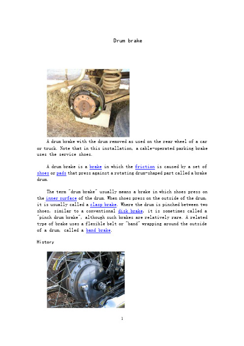
Drum brakeA drum brake with the drum removed as used on the rear wheel of a car or truck. Note that in this installation, a cable-operated parking brake uses the service shoes.A drum brake is a brake in which the friction is caused by a set of shoes or pads that press against a rotating drum-shaped part called a brake drum.The term "drum brake" usually means a brake in which shoes press on the inner surface of the drum. When shoes press on the outside of the drum, it is usually called a clasp brake. Where the drum is pinched between two shoes, similar to a conventional disk brake, it is sometimes called a "pinch drum brake", although such brakes are relatively rare. A related type of brake uses a flexible belt or "band" wrapping around the outside of a drum, called a band brake.HistoryA drum brake at the rear wheel of a motorbikeKawasaki W800The modern automobile drum brake was invented in 1902 by Louis Renault, though a less-sophisticated drum brake had been used by Maybach a year earlier. In the first drum brakes, the shoes were mechanically operated with levers and rods or cables. From the mid-1930s the shoes were operated with oil pressure in a small wheel cylinder and pistons(as in the picture), though some vehicles continued with purely-mechanical systems for decades. Some designs have two wheel cylinders.The shoes in drum brakes are subject to wear and the brakes needed to be adjusted regularly until the introduction of self-adjusting drum brakes in the 1950s. In the 1960s and 1970s brake drums on the front wheels of cars were gradually replaced with disc brakes and now practically all cars use disc brakes on the front wheels, with many offering disc brakes on all wheels. However, drum brakes are still often used for handbrakes as it has proven very difficult to design a disc brake suitable for holding a car when it is not in use. Moreover, it is very easy to fit a drum handbrake inside a disc brake so that one unit serves as both service brake and handbrake.Early type brake shoes contained asbestos. When working on brake systems of older cars, care must be taken not to inhale any dust present in the brake assembly. The United States Federal Government began to regulate asbestos production, and brake manufacturers had to switch to non-asbestos linings. Owners initially complained of poor braking with the replacements; however, technology eventually advanced to compensate.A majority of daily-driven older vehicles have been fitted with asbestos-free linings. Many other countries also limit the use of asbestos in brakes. Early automotive brake systems, after the era of hand levers of course, used a drum design at all four wheels. They were called drum brakes because the components were housed in a round drum that rotated along with the wheel. Inside was a set of shoes that, when the brake pedal was pressed, would force the shoes against the drum and slow the wheel. Fluid was used to transfer the movement of the brake pedal into the movement of the brake shoes, while the shoes themselves were made of a heat-resistant friction material similar to that used on clutch plates. This basic design proved capable under most circumstances, but it had one major flaw. Under high braking conditions, like descending a steep hill with a heavy load or repeated high-speed slow downs, drum brakes would often fade and lose effectiveness. Usually this fading was the result of too much heat build-up within the drum. Remember that the principle of braking involves turning kinetic energy (wheel movement) into thermalenergy (heat). For this reason, drum brakes can only operate as long as they can absorb the heat generated by slowing a vehicle's wheels. Once the brake components themselves become saturated with heat, they lose the ability to halt a vehicle, which can be somewhat disconcerting to the vehicle's operator.Self-applying characteristicDrum brakes have a natural "self-applying" characteristic.[1]The rotation of the drum can drag either or both of the shoes into the friction surface, causing the brakes to bite harder, which increases the force holding them together. This increases the stopping power without any additional effort being expended by the driver, but it does make it harder for the driver to modulate the brake's sensitivity. It also makes the brake more sensitive to brake fade, as a decrease in brake friction also reduces the amount of brake assist.Disc brakes exhibit no self-applying effect because the hydraulic pressure acting on the pads is perpendicular to the direction of rotation of the disc. Disc brake systems usually have servo assistance ("Brake Booster") to lessen the driver's pedal effort, but some disc braked cars (notably race cars) and smaller brakes for motorcycles, etc., do not need to use servos.Note: In most designs, the "self applying" effect only occurs on one shoe. While this shoe is further forced into the drum surface by a moment due to friction, the opposite effect is happening on the other shoe. The friction force is trying to rotate it away from the drum. The forces are different on each brake shoe resulting in one shoe wearing faster. It is possible to design a two-shoe drum brake where both shoes are self-applying (having separate actuators and pivoted at opposite ends), but these are very uncommon in practice.Drum brake designsRendering of a drum brakeDrum brakes are typically described as either leading/trailing or twin leading.[1]Rear drum brakes are typically of a leading/trailing design(For Non Servo Systems), or [Primary/Secondary] (For Duo Servo Systems) the shoes being moved by a single double-acting hydraulic cylinder and hinged at the same point.[1] In this design, one of the brake shoes will always experience the self-applying effect, irrespective of whether the vehicle is moving forwards or backwards.[1]This is particularly useful on the rear brakes, where the footbrake (handbrake or parking brake) must exert enough force to stop the vehicle from travelling backwards and hold it on a slope. Provided the contact area of the brake shoes is large enough, which isn't always the case, the self-applying effect can securely hold a vehicle when the weight is transferred to the rear brakes due to the incline of a slope or the reverse direction of motion. A further advantage of using a single hydraulic cylinder on the rear is that the opposite pivot may be made in the form of a double lobed cam that is rotated by the action of the parking brake system.Front drum brakes may be of either design in practice, but the twin leading design is more effective.[1]This design uses two actuating cylinders arranged so that both shoes will utilize the self-applying characteristic when the vehicle is moving forwards.[1] The brake shoes pivot at opposite points to each other.[1]This gives the maximum possible braking when moving forwards, but is not so effective when the vehicle is traveling in reverse.[1]The optimum arrangement of twin leading front brakes with leading/trailing brakes on the rear allows for more braking force to be deployed at the front of the vehicle when it is moving forwards, with less at the rear. This helps to prevent the rear wheels locking up, but still provides adequate braking at the rear when it is needed.[1]The brake drum itself is frequently made of cast iron, although some vehicles have used aluminum drums, particularly for front-wheel applications. Aluminum conducts heat better than cast iron, which improves heat dissipation and reduces fade. Aluminum drums are also lighter than iron drums, which reduces unsprung weight. Because aluminum wears more easily than iron, aluminum drums will frequently have an iron or steel liner on the inner surface of the drum, bonded or riveted to the aluminum outer shell.AdvantagesDrum brakes are used in most heavy duty trucks, some medium and light duty trucks, and few cars, dirt bikes, and ATV's. Drum brakes are often applied to the rear wheels since most of the stopping force is generated by the front brakes of the vehicle and therefore the heat generated in the rear is significantly less. Drum brakes allow simple incorporation of a parking brake. Drum brakes are also occasionally fitted as the parking (and emergency) brake even when the rear wheels use disk brakes as the main brakes. In this situation, a small drum is usually fitted within or as part of the brake disk also known as a banksia brake.In hybrid vehicle applications, wear on braking systems is greatly reduced by energy recovering motor-generators (see regenerative braking), so some hybrid vehicles such as the GMC Yukon hybrid and Toyota Prius (except the third generation) use drum brakes.Disc brakes rely on pliability of caliper seals and slight runout to release pads, leading to drag, fuel mileage loss, and disc scoring. Drum brake return springs give more positive action and, adjusted correctly, often have less drag when released.Certain heavier duty drum brake systems compensate for load when determining wheel cylinder pressure; a feature unavailable when disks are employed. One such vehicle is the Jeep Comanche. The Comanche can automatically send more pressure to the rear drums depending on the size of the load, whereas this would not be possible with disks.Due to the fact that a drum brakes friction contact area is at the circumference of the brake, a drum brake can provide more braking force than an equal diameter disc brake. The increased friction contact area of drum brake shoes on the drum allows drum brake shoes to last longer than disc brake pads used in a brake system of similar dimensions and braking force. Drum brakes retain heat and are more complex than discbrakes but are often times the more economical and powerful brake type to use in rear brake applications due to the low heat generation of rear brakes, a drum brakes self applying nature, large friction surface contact area, and long life wear characteristics(%life used/kW of braking power).Brake technology, just like suspension technology and fuel-system technology, has come a long way in recent years. What began in the '60s as a serious attempt to provide adequate braking for performance cars has ended in an industry where brakes range from supremely adequate to downright phenomenal. The introduction of components like carbon fiber, sintered metal and lightweight steel, along with the adoption of ABS, have all contributed to reduced stopping distances and generally safer vehicles (though ABS continues to provide controversy).Although drum brakes are often the better choice for rear brake applications in all but the highest performance applications, vehicle manufactures are increasingly installing disc brake system at the rear wheels. This is due to the popularity rise of disc brakes after the introduction front ventilated disc brakes. Front ventilated disc brakes performed much better than the front drum brakes they replaced. The difference in front drum and disc brake performance caused car buyers to purchase cars that also had rear disc brakes. Additionally rear disc brakes are often associated with high performance race cars which has increase their popularity in street cars. Rear disc brakes in most applications are not ventilated and offer no performance advantage over drum brakes. Even when rear discs are ventilated, it is likely that the rear brakes will never benefit from the ventilation unless subjected to very high performance racing style driving.DisadvantagesDrum brakes, like most other types, are designed to convert kinetic energy into heat by friction.[1]This heat is intended to be further transferred to atmosphere, but can just as easily transfer into other components of the braking system.Brake drums have to be large to cope with the massive forces that are involved, and they must be able to absorb and dissipate a lot of heat. Heat transfer to atmosphere can be aided by incorporating cooling fins onto the drum. However, excessive heating can occur due to heavy or repeated braking, which can cause the drum to distort, leading to vibration under braking.The other consequence of overheating is brake fade.[1]This is due to one of several processes or more usually an accumulation of all of them.1. When the drums are heated by hard braking, the diameter of the drum increases slightly due to thermal expansion, this means the brakes shoes have to move farther and the brake pedal has to be depressed further.2. The properties of the friction material can change if heated, resulting in less friction. This is usually only temporary and the material regains its efficiency when cooled,[1]but if the surface overheats to the point where it becomes glazed the reduction in braking efficiency is more permanent. Surface glazing can be worn away with further use of the brakes, but that takes time.3. Excessive heating of the brake drums can cause the brake fluid to vapourise, which reduces the hydraulic pressure being applied to the brake shoes.[1] Therefore less retardation is achieved for a given amount of pressure on the pedal. The effect is worsened by poor maintenance. If the brake fluid is old and has absorbed moisture it thus has a lower boiling point and brake fade occurs sooner.[1]Brake fade is not always due to the effects of overheating. If water gets between the friction surfaces and the drum, it acts as a lubricant and reduces braking efficiency.[1]The water tends to stay there until it is heated sufficiently to vapourise, at which point braking efficiency is fully restored. All friction braking systems have a maximum theoretical rate of energy conversion. Once that rate has been reached, applying greater pedal pressure will not result in a change of this rate, and indeed the effects mentioned can substantially reduce it. Ultimately this is what brake fade is, regardless of the mechanism of its causes.Disc brakes are not immune to any of these processes, but they deal with heat and water more effectively than drums.Drum brakes can be grabby if the drum surface gets light rust or if the brake is cold and damp, giving the pad material greater friction. Grabbing can be so severe that the tires skid and continue to skid even when the pedal is released. Grabbiness is the opposite of fade: when the pad friction goes up, the self-assisting nature of the brakes causes application force to go up. If the pad friction and self-amplification are high enough, the brake will stay on due to self-application even when the external application force is released.Another disadvantage of drum brakes is their complexity. A person must have a general understanding of how drum brakes work and take simple stepsto ensure the brakes are reassembled correctly when doing work on drum brakes. Incompetent mechanics should not attempt working on drum brakes.Re-arcingBefore 1984, it was common to re-arc brake shoes to match the arc within brake drums. This practice, however, was controversial as it removed friction material from the brakes and caused a reduction in the life of the shoes as well as created hazardous asbestos dust. Current design theory is to use shoes for the proper diameter drum, and to simply replace the brake drum when necessary, rather than perform the re-arcing procedure. Before you can appreciate the difference between drum and disc brakes, you have to understand the common principles that both systems use when stopping a car: friction and heat. By applying resistance, or friction, to a turning wheel, a vehicle's brakes cause the wheel to slow down and eventually stop, creating heat as a byproduct. The rate at which a wheel can be slowed depends on several factors including vehicle weight, braking force and total braking surface area. It also depends heavily on how well a brake system converts wheel movement into heat (by way of friction) and, subsequently, how quickly this heat is removed from the brake components. This is where the difference between drum brakes and disc brakes becomes pronounced.AdjustmentEarly drum brakes (before about 1955) required periodic adjustment to compensate for drum and shoe wear. If not done sufficiently often long brake pedal travel ("low pedal") resulted. Low pedal can be a severe hazard when combined with brake fade as the brakes can become ineffective when the pedal bottoms out.Self adjusting brakes may use a mechanism that engages only when the vehicle is being stopped from reverse motion. This is a traditional method suitable for use where all wheels use drum brakes (most vehicles now use disc brakes on the front wheels). By operating only in reverse it is less likely that the brakes will be adjusted while hot (when the drums are expanded), which could cause dragging brakes that would accelerate wear and increase fuel consumption.Self adjusting brakes may also operate by a ratchet mechanism engaged as the hand brake is applied, a means suitable for use where only rear drum brakes are used. If the travel of the parking brake actuator lever exceeds a certain amount, the ratchet turns an adjuster screw that moves the brake shoes toward the drum.There are different Self Adjusting Brake Systems. Basically can be divided in to RAI and RAD. RAI systems are much more efficient than RAD systems and have built in systems that avoids the systems to recover when the brake is over heating. The most famous RAI are developed by Lucas, Bendix, Bosch, AP. For RAD systems the most famous are Bendix, AP, VAG ( Volkswagen ) and FORD recovery systems.The manual adjustment knob is usually at the bottom of the drum and is adjusted via a hole on the opposite side of the wheel. This requires getting underneath the car and moving the clickwheel with a flathead screwdriver. It is important and tedious to adjust each wheel evenly so as to not have the car pull to one side during heavy braking, especially if on the front wheels. Either give each one the same amount of clicks and then perform a road test, or raise each wheel off the ground and spin it by hand measuring how much force it takes and feeling whether or not the shoes are dragging.Use in musicA brake drum can be very effective in modern concert and film music to provide a non-pitched metal sound similar to an anvil. Some have more resonance than others, and the best method of producing the clearest sound is to hang the drum with nylon cord or to place it on foam. Other methods include mounting the brake drum on a snare drum stand. Either way, the brake drum is struck with hammers or sticks of various weight.It is also commonly used in steelpan ensembles, where it is called "the iron."鼓式制动器鼓式制动器是由一组摩擦蹄片挤压一个叫做制动鼓的旋转鼓状部分实现摩擦动。
制动器相关的外文文献

hub and rotor assemblyA ventilated rotor is cast with a weblike construction between two friction surfaces.The webs radiate out from the center of the rotor, much like vanes or fins in a fan . As the rotor turns,air is drawn into the rotor at its center , flows between the friction surfaces, and is discharged along the outer edge . this cools the rotor . which drastically reduces the chances of brake fade , even during multiple hard stops .a splash shield protects the rotor and pads from road splashes and dirt . it is also shaped to channel the flow of air over the exposed rotor surfaces . as long as the car is moving , this flow of air helps to cool the rotor . the splash shield cannot be removed unless the rotor and caliper are first removed . replacement of the splash shield is necessary only when it has been damaged or when the spindle is replaced .caliper assemblya brake caliper converts hydraulic pressure into mechanical force . the caliper housing is usually a one-piece construction of cast iron or aluminum and has an inspection hole in the top to allow for lining wear inspection . the housing contains the cylinder bore . in the cylinder bore is a groove that seats a square-cut seal . this groove is tapered toward the bottom of the bore to increase the compression on the edge of the bore to increase the compression on the edge of the seal that is nearest hydraulic pressure . the top of the cylinder bore is also grooved as a seat for the dust boot . a fluid inlet hole is machined into the bottom of the cylinder bore and a bleeder valve is located near the top of the casting .a caliper can contain one , two , or four cylinder bores and pistons that provide uniform pressure distribution against the brake's friction pads . the pistons are relatively large in diameter and short in stroke to provide high pressure on the friction pad assemblies with a minimum of fluid displacement .basically the hydraulics of disc brakes are the same as for drum brakes , in that master cylinder piston forces the brake fluid into the wheel cylinders and against the wheel pistons .the disc brake piston is made of steel , aluminum , or fiberglass-reinforced phenolic resin . steel pistons are usually nickel-chrome plated for improved durability and smoothness . the top of the pistons is grooved to accept the dust boot that seats in a groove at the top of the cylinder bore and also in a groove in the piston . the dust boot prevents moisture and road contamination from entering the bore .a piston hydraulic seal prevents fluid leakage between the cylinder bore wall and the piston . this rubber sealing ring also acts as a retracting mechanism for the piston when hydraulic pressure is released , causing the piston to return in its bore (Figure 46-3). when hydraulic pressure is diminished , the seal functions as a return spring to retract the piston .In addition,as the disc brake pads wear , the seal allows the piston to move farther out to adjust automatically for the wear , without allowing fluid to leak.Since the brake pads need to retract only slightly after they have been applied,the piston moves back only slightly into its bore.The additional brake fluid in the caliper bore keeps the piston out and ready to clamp the surface of the rotor.fixed caliper disc brakesfixed caliper disc brakes have a caliper assembly that is bolted in a fixed position and does not move when the brakes are applied . the pistons in both sides of the caliper come inward to force the pads against the rotor (Figure 46-4).floating caliper disc brakesa typical floating caliper disc brake is a one-piece casting that has one hydraulic cylinder and a single piston . the caliper is attached to the spindle anchor plate with two threaded locating pins .a Teflon sleeve separates the caliper housing from each pin and the caliper slides back and forth on the pins as the brakes are actuated . when the brakes are applied , hydraulic pressure builds in the cylinder behind the piston and seal . because hydraulic pressure exerts equal force in all directions , the piston moves evenly out of its bore .the piston presses the inboard pad against the rotor . as the pad contacts the revolving rotor , greater resistance to outward movement is increased , forcing pressure to push the caliper away from the piston , this action forces the outboard pad against the rotor (figure 46-5). however , both pads are applied with equal pressure .sliding caliper disc brakesWith a sliding caliper assembly , the caliper slides or moves sideways when the brakes are applied.As mentioned previously ,in operation,these brakes are almost identical to the floating type.But unlike the floating caliper ,the sliding caliper does not float on pins or bolts attached to the anchor plate (Figure 46-6).It has angular machined surfaces at each end that slide in mating machined surfaces on the anchor plate.This is where the caliper slides back and forth .Some sliding calipers use a support key to locate and support the caliper in the anchor plate . the caliper support key is inserted between the caliper and the anchor plate . a worn support key may cause tapered brake pad wear . always inspect the support keys when replacing brake pads . also make sure they are lubricated when reassembling the unit .brake pad assemblybrake pads are metal plates with the linings either riveted or bonded to them . pads are placed at each side of the caliper and straddle the rotor . the inner brake pad , which is positioned against the piston , is not inter changeable with the outer brake pad . the linings are made of semimetallic or other nonasbestos material (Figure 46-7).DISC PAD WEAR SENSORSSome brake shoe pads have wear sensing indicators.The three most common design weal sensors are audible,visual,and tactile .Audible sensors are thin,spring steel tabs that are riveted to or installed onto the edge of the pad's backing plate and are bent to contact the rotor when the lining wears down to a point that replacement is necessary .At that point,the sensor causes a high-pitched squeal whenever the wheel is turning,except when the brakes are applied,then the noise goes away.The noise gives a warning to the driver that brake service is needed and perhaps saves the rotor from destruction (Figure 46-8). the tab is generally installed toward the rear of the wheel .visual sensors inform the driver of the need for new linings . this method employs electrical contacts recessed in the pads that touch the rotor when the linings are worn out . this completes a circuit and turns on a dashboard warning light . this system is found mostly on imports .tactile sensors create pedal pulsation as the sensor on the rotor face contracts the sensor attached to the lower portion of the disc pad .cautionas disc brake pad linings wear thin , more brake fluid is needed in the system.Customer careExcessive heat liquefies the resin binder that holds the brake pad material together . once liquefied , the binder rises to the surface of the pad to form a glaze .A glazed pad may cause squealing because more heat is needed to achieve an amount of friction equal to a pad in good condition.One common cause of pad glazing is the improper break-in of the pads.Remember to inform customers that unnecessary hard braking during the first 200 miles(320km)of a pad’s life can generate enough heat to glaze the pads and ruin the quality of the work just performed .There are Pads now available that require no break-in time . Rear Disc / Drum (Auxiliary Drum) Parking BrakeThe rear disc / drum or auxiliary drum parking brake arrangement is found on some vehicles . on these brakes , the inside of each rear wheel hub and rotor assembly is used as the parking brake drum(Figure 46—9) . The auxiliary drum brake is a smaller version of a drum brake and is serviced 1ike any other drum brake .Rear Disc Parking BrakesInstead of using an auxiliary drum and shoes to hold the vehicle when parked,these brakes have a mechanism that forces the pads against the rotor mechanically.One method for doing this is the ball-and-ramp arrangement.Another method that is found on many vehicles has a threaded,spring-loaded pushrod (Figure 46-10).As the parking brakes are applied ,a mechanism rotates or unscrews the pushrod ,which in turn pushes the piston out .Other types of actuating systems for rear disc brakes include the use of a variety of cams.DISC BRAKE DIAGNOSISMany problems that are experienced on vehicles with disc brakes are the same ones that are evident with drum brake systems .There are some problems that occur only with disc brakes.Before covering the typical complaints , it is important to remind you to get as much information as possible about the complaint from the customer.Then road test the vehicle to verify the complaint.A complete inspection of the rotor , caliper , and pads(Figure 46-11) should be done anytime you are working on the brakes.What follows is a brief discussion of common complaints and their typical causes.The red warning light indicates there is a problem in the regular brake system , such as low brake fluid levels or that the parking brake is on . a low fluid light may be present in addition to the red brake warning light . whenever the fluid is low , you should suspect a leak or very worn brake pads .The yellow or amber brake warning light is tied into the antilock brake system . this light turns on for two reason : the ABS system is performing a self-text or there is a fault in the ABS system .A blue warning light lets the driver know the wheels are slipping because of poor road conditions . more discussion on the amber and blue lights is given in the next chapter of this book .Pulsating pedalCustomers will feel a vibration or pulsation in the brake pedal when the brakes are applied if a brake rotor is warped . if this symptom exists , check the rotors for runout and parallelism . a warped rotor should be replaced and is often caused by improper tightening of the wheel lug nuts . in fact , uneven lug nut torque can cause a pulsating brake pedal . you should be aware that pedal pulsation is normal on vehicles with ABS when the antilock brake system is working . Spongy PedalWith a spongy pedal , the customer will probably feel the need to pump the brake pedal to getgood stopping ability . the complaint may also be described as a soft pedal . this problem is caused by air in the hydraulic system . Although bleeding the system may remove the air,you should always question how the air got in there .Check for leaks and for proper master cylinder operation.Hard PedalThe driver’s complaint of a hard pedal normally indicates a problem with the power brake booster . However it can also be caused by a restricted brake line or hose . Carefully check the lines and hoses for damage . Feel the brake hoses . if they seem to have lost their rigidity , the hose may have collapsed on the inside and this is causing the restriction . Restrictions can also be caused by frozen caliper or wheel cylinder pistons.Dragging BrakesDragging brake make the vehicle feel as if it has lost or is losing power as it drives down the road . the problem also wastes a lot of fuel and generates destructive amounts of heat that can cause serious brake damage and brake failure . while trying to find the cause of this problem , check the parking brake first . make sure it is off . check the rear wheels to make sure the parking brakes are released when they should be . if the problem is not in the parking brakes , check for sticky or seized pistons at the calipers and wheel cylinders .Grabbing BrakesWhen the brakes seem to be overly sensitive to pedal pressure , they are grabbing . normally this problem is caused by contaminated brake linings . if the lings are covered or saturated with oil , find the source of the oil and repair it . then replace the pads and refinish or replace the rotor .NoiseIf the customer’s complaint is noisy brakes , v erify during the road test that the problem is in the brakes . if the noise is caused by the brakes , pay attention to the type of noise and let that lead to the source of the problem . remember , some brake pads have wear sensors that are designed to make a high-pitched squeal when the pads are worn . other causes could be the rotor rubbing against the splash shield or that something has become wedged between the rotor and another part of the vehicle . noise may also be caused by failure to install all of the hardware when placing a caliper or brake pads in service .PullingWhen a vehicle drifts or pulls to one side while cruising or when braking , the cause could be in the brake system or in the steering and suspension system . check the inflation of the tires , the tires’ tread condition , and verify that the tires on each axle are the same size . check the operation of the brakes . if only one front wheel is actually doing the braking , the vehicle will seem to stumble or pivot on that one wheel . if no problems are found in the brake system , suspect an alignment or suspension problem .SERVICE PRECAUTIONSThe following general service precautions apply to all disc brake systems and should always be followed :1. Be sure the vehicle is properly centered and secured on stands or a hoist .2. If the vehicle has antilock brakes , depressurize the system according to the procedures given in the service manual .3. Disconnect the battery ground cable .4. Before any service is performed , carefully check the following :■tires for excessive wear or improper inflation■wheels for bent or warped rims■wheel bearings for looseness or wear■suspension components to see if they are worn or broken■brake fluid level■master cylinder , brake lines or hoses , and each wheel for leaks5. During servicing , grease , oil , brake fluid , or any other foreign material must be kept ff the brake linings , caliper , surfaces of the disc , and external surfaces of the hub . handle the brake disc and caliper in such a way as to avoid deformation of the disc and nicking or scratching of the brake linings .6. when a hydraulic hose is disconnected , plug it to prevent any foreign material from entering .7. never permit the caliper assembly to hang with its weight on the brake hose . support it on the suspension or hang it by a piece of wire .8. inspect the caliper for leaks . if leakage is present , the caliper must be over hauled .9. when using compressed air to remove caliper pistons , avoid high pressures . a safe pressure to use is 30 psi (207 kPa).10. clean the brake components in either denatured alcohol or clean brake fluid . do not use mineral-based cleaning solvent such as gasoline , kerosene , carbon tetrachloride , acetone , or paint thinner to clean the caliper . it causes rubber parts to become soft and swollen in an extremely short time .11. lubricate any moving member such as the caliper housing or mounting bracket to assure a free-moving action . use only recommended lubricant .12. before the brake pads are installed , apply a disc brake noise suppressor to the back of the pads to prevent brake squeal . for best results , follow the directions on the container .13. obtain a firm brake pedal after servicing the brakes and before moving the vehicle . be sure to road test the vehicle .14. always torque the lug nuts when installing a wheel on a vehicle with disc brakes . never use an impact gun to tighten the lug nuts . warpage of the rotor could result if an impact gun is used . Before beginning brake work , remove about two-thirds of the brake fluid from the master cylinder’s reservoir . if this is not done , the fluid could overflow and spill when the pistons ar e forced back into the caliper bore , possibly damaging the painted surfaces . replace the cover . discard old brake fluid .Another common procedure (and perhaps a better way) is to open the caliper bleeder screw and run a hose down to a container to catch the fluid that is expelled when the piston is forced back into its bore . this also makes it easier to move the piston .If the bleeder screws are frozen tight with corrosion , it is sometimes possible to free them using a propane torch and penetrating oil . of course , the caliper has to be removed from the car , taken to a bench and worked on there.If the bleeder screws cannot be loosened,they can be drilled out and the caliper retapped for an insert , orthe caliper can be replaced with a new or rebuilt unit . the bleeder screw should be removed when doing an overhaul .warningWhen using the propane torch to loosen a bleeder screw , use it with extreme care .GENERAL CALIPER INSPECTING AND SERVICINGFrequently , caliper service involves only the removal and installation of the brake pads . however , since the new pads are thicker than the worn-out set they replace , they locate the piston farther back in the bore where dirt and corrosion might cause the seals to leak . for this reason , it is often good practice to carefully inspect the calipers whenever installing new pads . of course , it is also good practice to true-up or replace the rotors when replacing brake pads . When bench working a caliper assembly , use a vise that is equipped with protector jaws . excessive vise pressure causes bore and piston distortion .Caliper RemovalTo be able to replace brake pads , service the rotor , or to replace the caliper , the caliper must be removed . the procedure for doing this will vary according to caliper design . always follow the specific procedures given in a service manual . use the following as an example of these procedures :1. remove the brake fluid from the master cylinder .2. raise the vehicle and remove the wheel and tire assembly .3. on a sliding or floating caliper , install a C-clamp with the solid end of the clamp on the caliper housing and the screw end on the metal portion of the outboard brake pad . tighten the clamp until the piston bottoms in the caliper bore (figure 46-12), then remove the clamp.Bottoming the piston allows room for the brake pad to slide over the ridge of rust that accumulates on the edge of the rotor.4. On threaded-type rear calipers . the piston must be rotated to depress it.This requires a special tool (Figure 46-13).5. Disconnect the brake hose from the caliper and remove the copper gasket or washer and cap the end of the brake hose.If only the brake pads are to be replaced,do not disconnect the brake hose.6. Remove the two mounting brackets to the steering knuckle bolts .Support the caliper when removing the second bolt to prevent the caliper from falling.7. On a sliding caliper , remove the top bolts , retainer clip , and antirattle springs(Figure 46-14) . On a floating caliper , remove the two special pins that hold the caliper to the anchor plate(Figure 46-15) . On a fixed caliper , remove the bolts holding it to the steering knuckle . On all three types , get the caliper off by prying it straight up and lifting it clear of the rotor .Brake Pad RemovalDisc brake linings should be checked periodically or whenever the wheels are removed.Some calipers have inspection holes in the caliper body.If they do not,the brake pads can be visually inspected from the outer ends of the caliper .If you are not sure the pads are worn enough to warrant replacement , measure them at the thinnest part of the pad . compare this measurement to the minimum brake pad lining thickness listed in the vehicle’s service manual , and replace the pads if needed .When a pad on one side of the rotor has worn more than on the other side , the condition is called uneven wear . uneven pad wear of often means the caliper is sticking and not giving equal pressure to both pads . on a sliding caliper , the problem could be caused by poor lubrication of or deformation of the machined sliding areas on the caliper and/or anchor plate . a slightly tapered wear pattern on the pads of certain mode is caused by caliper twist during braking . it is normal if it does not exceed 1/8-inch (3-mm) taper from one end of the pad to the other (figure46-16) .Sliding or floating caliper must always be lifted off the rotor for pad replacement . fixed calipers might have pads that can be replaced by removing the retaining pins or clips instead of having to lift off the entire caliper . brake pads may be held in position by retaining pins , guide pins , or a support key . note the position of the shims , anti-rattle clips , keys , bushings , or pins during disassembly . a typical procedure for replacing brake pads is outlined in Photo Sequence 50 , included in this chapter .If only the pads are going to be replaced , lift the caliper off the rotor and hang it up by a wire . remove the outer pad and inner pad . remove the old sleeves and bushings and install new ones . replace rusty pins on a floating caliper to provide for free movement . transfer shoe retainers , which can be clips or springs , onto the new pads .。
货车鼓式制动器的发展历史

货车鼓式制动器的发展历史货车是现代物流体系不可或缺的组成部分,而制动器则是其最为重要的安全保障。
作为一种历史悠久、经久不衰的制动器类型,鼓式制动器被广泛用于货车这一领域中。
在它的发展历史中,我们可以看到人类科技的不断革新,以及科技进步所带来的物质生产能力的提升。
一、早期鼓式制动器最早的鼓式制动器可以追溯到19世纪初,当时的制动器是通过手动操作来实现的。
其中一个典型的例子便是由George Westinghouse在1869年制造的机车制动器。
这一制动器利用了气压作为动力,通过压力传导来实现牵引车的刹车作用。
这种制动器可能看起来并不那么高效,但绝对已经可圈可点。
二、蒸汽时代的鼓式制动器随着蒸汽技术的普及,鼓式制动器也出现了一些较大的发展。
最大的差异在于,新型鼓式制动器功能更为完备,并且使用起来更加方便。
这些制动器常常基于蒸汽驱动来进行刹车,比如在对蒸汽机车的再利用中,这些更高级的鼓式制动器得以发挥出更大的作用。
三、简化的气制动器到了20世纪初,气制动器的技术正逐渐发展出来,并且在货车制动器的领域里备受欢迎。
如果将其与早期的鼓式制动器相比较,可以发现它们不仅更高效,而且使用更加简单。
在这个时期,气制动器开始代替以前利用传导气压来制动货车的手动制动器。
四、现代货车鼓式制动器的发展进入21世纪后,随着计算机技术的提高和发展,鼓式制动器的功能达到了空前的高峰。
同任何一种机械设备一样,它的设计和使用也变得更加趋向高效、智能化。
其中一个最大的改变在于,鼓式制动器在现代货车中的使用非常普遍,并且已经根据不同的需求划分成了许多不同的类型。
例如,有一些制动器是为了在高速行驶中实现高速制动而设计的,还有一些则是为了在滑行状态下保持制动压力而特别设计的。
总的来说,鼓式制动器作为一种安全性高、在历史长河中经久不衰的制动器,其重要性在现代物流体系中逐渐体现出来。
我们相信,未来在科技不断进步的助力下,它还将继续随着时代的变迁,不断地得到新的发展。
汽车后轮驻车制动器的特点与维修外文文献翻译、中英文翻译、外文翻译
汽车后轮驻车制动器的特点与维修外文文献翻译、中英文翻译、外文翻译附录Car rear parking brake is well known characteristics andmaintenanceparking brake, the car must have one of the braking device. Iveco second-generation products in vehicle brakes, parking brake is a mechanical control mechanism and the rear drum brake combination. Such a structure, so that not only after the brake drum brake and parking brake also played a role. With the use of rear disc brake, Turin-V vehicle parking brake with the rear brakes will be fixed in the form and change. If the rear wheels with drum brakes, while maintaining the basic structure of the original second-generation products; the use of a disc brake, rear wheel will have to configure a dedicated parking brake. On the disc brake is concerned, there is the structure with the parking brake disc brake, the parking braking force acts on the brake discs on both sides of the work surface, such a brake complex structure, relatively somewhat less reliable. Turin-V cars equipped with dual-piston sliding front disc brakes have specifically set up after the parking brake. The role of the parking brake force to the brake drum inner disk on the work surface, so that the brake disc has two separate friction surface, life can be improved, brake caliper is also simplified the structure. Turin-V car rear parking brake device manipulated by a mechanical parking brake and special climate of two parts (brake disc for the traffic, shared parking brake parts.)1, mechanical control mechanism to maintain the basic structure of the original second-generation products, mainlycomposed of pieces with a handle, the first wire cable, ratchet plate, adjust the threaded sleeve, locking nut, after the wire cable and the guide disc and so on.2, the special structure and principle of the parking brake disc brakeafter the match with a special parking brake, parking brake after the special bottom bracket through eight holes, and the rear axle relative to the fixed axle shaft flange bolts. Before and after the friction shoe upper and lower ends are pulled tight against the return spring on the role of regulation under the pull pin and arm in the middle and the bottom through the active support underwriting phase. Slide the gear on the pin on the regulator can adjust the elongation or shortening the length of sales to adjust the friction inside the shoe and drum brake disc space. Role in pulling arm, it is subject to manipulation after the wire cable, when the pull the handbrake lever, the role will be the central axis of the pin pulling arm as a fulcrum, the friction shoe before and after distraction, so that the drum with an effective brake disc friction torque, and thus play a role in the private parking brake parking brake in the brake plate bracket, and another two holes for the installation of rear brake clamp assembly. After the band drum and wheel brake disc will be Yi, after the special parking brake, brake caliper assembly, and so orderly together. 3, special parking brake after the decomposition and synthesis in vehicle rear wheels when the removal of the Yi, a number of components such as rear brake disc, you can special parking brake on the decomposition and synthesis, the basic process steps are as follows: ? From the front Bu friction shoe, remove the return spring, spin off the short length adjustment, remove the friction between the supportshoe underwriting folder, you can remove the friction shoe.Remove the branch underwriting, Hou Lasuo loose parking brake pull arm connected with the role, remove the effect of the second arm pull the wheel speed sensor mounting bracket removed, you can remove the sensor.Remove the axle casing under the flange and the eight mounting bolts, then remove the parking brake bottom bracket.according to the requirements of the drum brakes on the parts removed for cleaning checks, abandoned exceeded the difference of wear parts. ? synthesis by decomposition of the reverse steps. After synthesis,measured with a vernier caliper before the hind piece diameter, while toggle adjustment pin 1, the diameter value than 172'0 ', a small 0.4} 1 mm. After the adjustment of parking brake parking brake because the brake after the non-automatic compensating clearance, the use of a period of time, the brake gap will gradually increase, reflecting the tension in the handle spine when the number of teeth affected, will exceed the number of (normal number of teeth affected 4} 6), which will affect the rear wheel in vehicle performance. To this end, promptly after the parking brake adjustment. Adjusted as follows: ? from the top rear of t he car, and to support the frame bracket, then remove the rear wheels;Loosen the parking brake cable adjusting screw lock nut sets;? Remove the top long after the parking brake hole rubber plug, the use of special tools (99,372,249) toggle adjustment pin gear, so that before and after the friction shoe distraction, resulting in hand can not turn the plate so far;loose again with special tools to adjust the pin gear aside, the system Fixed disk free to rotate (brake gap of about 0.2}0.5mrri), re-built the rubber plug in the hole, refitted the rear wheels; ? Parking in the cab pulling teeth sound system to the third position of the handle and tighten the adjustment screw sets can not be pulled up by hand until the wheel rotates;Pull down and re lease the parking brake lever 3} 4, on the whole device after the parking brake adjustments, and check the final tightening when the handle is 6 Maximum stroke teeth, and finally tighten the adjusting screw lock nut sets, and lowered cars.汽车后轮驻车制动器的特点与维修众所周知,驻车制动是汽车必备的制动装置之一。
制动器的英文版及翻译
The BrakesThe brakes function by absorbing in friction the energy possessed by the moving car. In so doing they convert the energy into hear. There are tow types of brakes, the drum brake and the disc brake. Either or both types may be fitted. But where both types are used it is usual for the disc brakes to be fitted to the front wheels. In both drum and disc brakes, a hydraulic system applies the brakes. The hydraulic system connects the brake pedal to the brake parts at each wheel.1 、Drum BrakesThe drum brake consists of a pair of semicircular brake shoes mounted on a fixed back plate and situated inside a drum. This drum is fixed to the road wheel and rotates with it .One end of each shoe is on a pivot and a spring holds the other end in contact with the piston of a hydraulic cylinder.(In front brakes it is usual to use two hydraulic cylinders in order to equalize the pressures exerted by the shoes, as shown in Fig.7.1)Each shoe is faced with material ,known as brake lining ,which produces high frictio nal resistance.The hydraulic system comprises a master cylinder and the slave cylinders which are the cylinders on the road wheels. The slave cylinders are connected to the master cylinder by tubing and the whole system is filled with hydraulic fluid .A piston in the master cylinder is connected to the brake pedal, so that when the driver depresses the pedal the fluid is forced out to each slave cylinder and operates their pistons. The fluid pushes the pistons out of their cylinders. They ,in turn, push against the inner ends of the brake shoes and force them against the drums in each wheel. We say that the brakes are on. This friction of the shoes against the drums, which are fixed to the road wheels, slows down or stops the car.As the brake pedal is allowed to come up, the hydraulic fluid returns to its original position, the pistons retract, and a spring attached to each brake shoe returns it also to its original position. Free of the brake drum. Now we say that the brakes are off.(Fig.7.2)The brakes may also be operated by mechanical linkages from the foot pedal and hand brake lever. Common practice is to operate both front and rear brakes hydraulically with a secondary mechanical system operating the rear brakes only from the hand lever. One of the great advantages of hydraulic operation is that the system is self-balancing, which means that the same pressure is automatically produced at all four brakes, whereas mechanical linkages have to be very carefully adjusted for balance. Of course, if more pressure is put on one of the brakes than on the others there is a danger that the car will skid.The mechanical linkage on the rear brakes is a system of rods or cables connecting the handbrake lever to the brake-shoe mechanism, which work entirely independently of the hydraulic system. Drum brakes are prone to a reduction in the braking effort, known as “fade”, caused by the overheating of the brake linings and the drum. Fade can affect all or only some of the brakes at a time, but it is not permanent, and full efficiency returns as soon as the brakes have cooled down. However, fading is unlikely to occur except after the brakes have been used repeatedly in slowing the car from a high speed or after braking continuously down a steep hill. Descending such a hill, it would have been preferable to use engine braking by changing down into a lower gear. Drum brakes can be made less prone to fade by improving the cooling arrangements, by arranging formore air to be deflected over them, for example.2 Disc BrakesThe disc brake consists of a steel disc with friction pads operated by slave hydraulic cylinders. The steel disc is attached to the road wheel and rotates with it. Part of this steel disc is enclosed in a caliper. This caliper contains two friction pads,one on each side of the disc, and two hydraulic cylinders, one outside each pad. The pads are normally held apart by a spring, but when the driver depresses the brake pedal, pistons from the hydraulic cylinders force the pads against the sides of the disc. Because the disc is not enclosed all the way round, the heat generated when the brakes are applied is dissipated very much more quickly than it is from brake shoes which are entirely enclosed inside a drum. This means that disc brakes are less prone to fade than drum brakes.(Fig.7.3)3 、Anti-lock Brake System (ABS)The function of an anti-lock, or anti-skid, braking system is to prevent the wheels from locking under hard braking. Maximum braking force is obtained just before the wheels lock and skid. Such anti-skid system ate useful on slippery surfaces, such as ice and snow, where the wheels may lock easily. Locked wheels are dangerous because the car needs a much longer distance to stop. Locked wheels also can cause the driver to lose control.The system uses a sensor that knows when one wheel (or a pair of wheel) is skidding. (Fig.7.4) The sensor sends a signal to a computer, which signals a modulator valve. The modulator connects into the hydraulic system and can momentarily release the brake pressure and prevent the wheels from locking.(The pressure release is so fast that a driver is seldom aware of it.) pressure is then reapplied until the sensor again senses that the wheel is about to lock up. Thus, this system keeps the wheels as close to lock up as possible, without actually allowing the wheels to lock up and skid. This is called incipient lock up. Maximum braking occurs at that point. If any part of the system should fail to work, the system goes into a “fail-safe” mode. The brakes operate normally, as they would on a car that is not equipped with ABS. Today , ABS is an optional or standard feature that typically is found on expensive luxury cars and sports cars. In the future, ABS may be available for all cars.3.1、ABS overviewAnti-lock braking system is using the body of a rubber balloon, while hitting the brakes, will give brake oil pressure, feeding through to the ABS body, using of the air in the middle of the air layer to return the pressure, make wheels evade the locked points. When the wheel will arrive next locked point, brake oil pressure makes balloon in a repeat function, so can function eight to thirty times in one second equivalent constantly brake, relax, namely, similar to the "mechanical braking ". Therefore, ABS anti-lock braking system, can avoid the orientation losing control , the wheel’s lateral sliding coming up and the wheels rubbing on one point with the ground without being locked in the emergency brake,so it can make the brake friction efficiency achieves ninety percent. It also can reduce the braking consumption and prolong the brake wheel drum, disc and tire twice with the service life of the vehicle in the ABS. On the dry tarmac road or on snowy or on rainy days, the slippery performance reached 80% - 90%, 30% -10%, 15% - 20%. Ordinary braking system on a wet road surface brake, or in the emergency brake, it’s easy for wheels to be locked owing to the braking force exceeds the friction force of the tires and ground. In recent years, the consumers of the vehicle emphasis on the safety , so most of the cars have ABS listed as standard. Without ABS, emergency brake usually cause tire locked, then, the rolling friction becomes sliding friction, as a result, braking force dramatically decreased. And if front wheels are locked first, the vehicle will lose the steering ability; if the rear tires are first locked, the vehicle is easy to slide laterally , so the direction becomes impossible to control. Through electronic or mechanicalcontrol, the ABS system controls the braking fluid pressure at a fast speed to avoid the wheelslocked. Insure the tire have the biggest braking force and the turning ability when braking, and make the vehicle have the ability to evade the obstacles in emergency braking. With the rapid development of the automotive industry, safety increasingly become the important basis of that people choose and buy cars. At present the widespread adoption of holding brake system (ABS) that people can fully meet the safety of requirements. Automobile brake prevent embrace system, referred to as the ABS, is to improve the car an important device passive safety. Someone said brake prevent embrace system is auto safety measures relay belts after another major progress. Automobile braking system is the bus passengers safety is the most important relationship to one of the second systems. With the rapid development of the automotive industry, automobile safety for people appeals more and more attention. Automobile brake prevent embrace system, is another major progress to improve the safety.ABS braking system is controlled by automobile microcomputer, when braking, it can keep the wheel rotating to help driver control vehicle parking safely. The anti-locked braking system detects wheel speed by speed sensor, and then send the wheel speed signals to the microcomputer. The microcomputer controls wheel slipping rate by increasing or decreasing the brake pressure repeatedly according to the input wheel speed to keep wheel rotate. In braking process, keeping wheel rotate not only ensures the ability of controlling driving direction, but also provides higher brake force than the locked wheel in most circumstances, .3.2、The working principle of ABSIt includes control devices and ABS warning lights, in different ABS system, the structure of brake pressure adjusting device and working principle of electronic control devices are often different, the internal structure and control logic of ABS system usually includes the wheel speed sensors, brake pressure adjusting device, electronic identical and so on. In common ABS system, each wheel is installed a rotational speed sensor on the wheel speed, input the signal to electronic control device. The electronic control unit states monitoring and determination according to each wheel speed sensors’ sign al about each wheel movement, and has formed the corresponding control instruction. Brake pressure adjusting device is mainly composed by pressure regulating solenoid valves, electric pump composition and liquid container components compose an independent whole, braking main cylinder and the cylinder brake wheel connected by the brake pipe. Brake pressure adjusting device is controlled by the electronic unit to control all brake wheel cylinders’ brake pressure. The working process of ABS can be divided into general braking, brake pressure kept brake pressure decrease and brake pressure increase stage. In general braking phase, ABS doesn't intervene brake pressure control, pressure regulating electromagnetic valve assembly in various into liquid solenoid valves are no electricity and is open, each produced liquid are no electricity and electromagnetic valve is in the closed position, electric pump also operates without electricity, and brake main cylinder to each brake wheel cylinder brake lines are in communication condition, and the brake wheel cylinder to liquid brake lines are in close condition, the brake wheel cylinder brake pressure change with the output pressure brake master cylinder, the brakingprocess at this time is completely the same with conventional braking system braking process.In braking process, when the electronic control detects that the wheels primarily tend to embrace dies according to the wheel speed sensors of the wheel speed signal input, ABS came into the braking anti-lock process. For example, when the electronic control unit judges the front-right wheel tends to embrace, the electronic control unit will make control scrape the dynamic pressure front-right wheel failure into liquid solenoid valves electricity, make the fluid electromagnetic valve closed, brake main cylinder output brake fluid no longer enter into brake wheel cylinder, right now, right at the end of a fluid electromagnetic valve still energized and closed, the right brake wheel cylinder brake fluid also won't outflow, the right brake wheel cylinder scraping dynamic pressure stays certain, and other arms tend to be dead wheel with still brake pressure braking main cylinder and the increase of output pressure increases; If the right brake wheel cylinder brake pressure keep certain, the electronic control unit front-right wheel failure still tend to judge lock, the electronic control unit and move out liquid solenoid valves also electrify into a state of opening, the part right brake wheel cylinder brake wave will pass is open from fluid electromagnetic valve flow back to liquid container, make right brake wheel cylinder brake pressure holding diminishes quickly front-right wheel failure will start to eliminate death trend, with the right brake wheel cylinder brake pressure decreases, the front-right wheel under the action of inertia force will speed up gradually; accelerate gradually When the electronic control device determines the lock front-right wheel failure to completely eliminate according to the wheel speed sensors input signal, the electronic control unit makes right into the fluid electromagnetic valve and a liquid solenoid valves are without electricity, make into fluid electromagnetic valve to open, use liquid into closed electromagnetic valve, also make electric pump operation, energized to brake wheel cylinder pump brake fluid, output by brake main cylinder brake fluid electromagnetic valve into the right brake wheel cylinders, make right brake wheel cylinder brake pressure increased rapidly, opening up a front-right wheel failure and slow rotation. ABS control the sliding rate of wheels which tend to be locked through holding the brake force of wheels that tends to be locked repeatedly ,adhesion coefficient is in peak within the scope of the sliding rate, until the bus speed reduced to very low or brake main cylinder pressure no longer tend to be locked. Brake pressure to adjust cycle of frequency can reach 3 ~ 20HZ. In the ABS each has on the fluid and the fluid electromagnetic valve in corresponding at each brake wheel cylinder, but by the electronic control device to control, therefore, respectively, the brake wheel cylinder brake pressure can be independently adjustment so that four wheels are not occur braking lock phenomenon. Although various ABS structure form and working process is not exactly the same, are based on the brake holding pressure adaptive cycle adjustment of wheel which tends to be locked, to prevent the controlled wheels holding in death occurred when brake.3.3、ABS functionThe braking performance is one of main auto performance, it is also related to the security of driving. Evaluate the braking performance of a car , the basic index is brake acceleration ,braking distance and direction of braking time and braking stability.Braking stability points to that the vehicle can still be specified in the direction of auto brake when driving in the direction of track. If cars proceed high-speed brake (especially when emergency brake) and make the wheel fully embrace die, it is very dangerous. If front wheel is locked, it will make cars lose steering ability. If the rear wheel is locked, it will appear to swing tail or switching (running deviation, sideslip) especially in the road is all wet slippery case, it will cause the traffic safety great harm. Automobile braking force depends on the brake friction, but the braking force which can make the car brake to slow, and also restricted by ground adhesion coefficient. When brake produces braking force increases to certain value, the tires will appear slipping on the ground. Its sliding rateδ = (Vt - Va) / Vt x 100%δ: delta - sliding rate;Vt - theoretical speed of the car;Va - the actual speed of the car.According to the experiments confirm, when wheel sliding rate delta range from 15% to 20% , the ground adhesion coefficient reach maximum, therefore, in order to get the best braking effect, we must control the slip rate in 15% ~ 20% range.ABS function will namely decrease the brake force when the wheels will embrace dies, , and when the wheel will not hold died and increase braking force, so repeated action, braking effect is the best.3.4、The problems needing attention when ABS is used(1) After replace brake or replace hydraulic brake system components, it should exhaust the air in the brake pipe, lest affect braking system work normally.(2)The car equipped with ABS should be replaced every year. Otherwise, brake fluid hygroscopic is very strong, water will not only reduce the boiling point to make it easy to produce corrosion, and still can cause braking performance recession.(3) To examine ABS braking system should pull power firstly.制动系简介制动器通过摩擦的形式吸收运动车辆所具有的能量而起作用。
(完整版)汽车制动系统英文文献及翻译)

Automobile Brake SystemThe braking system is the most important system in cars. If the brakes fail, the result can be disastrous. Brakes are actually energy conversion devices, which convert the kinetic energy (momentum) of the vehicle into thermal energy (heat).When stepping on the brakes, the driver commands a stopping force ten times as powerful as the force that puts the car in motion. The braking system can exert thousands of pounds of pressure on each of the four brakes.Two complete independent braking systems are used on the car. They are the service brake and the parking brake.The service brake acts to slow, stop, or hold the vehicle during normal driving. They are foot-operated by the driver depressing and releasing the brake pedal. The primary purpose of the brake is to hold the vehicle stationary while it is unattended. The parking brake is mechanically operated by when a separate parking brake foot pedal or hand lever is set.The brake system is composed of the following basic components: t he “master cylinder” which is located under the hood, and is directly connected to the brake pedal, converts driver foot’s mechanical pressure into hydraulic pressure. Steel “brake lines” and flexible “brake hoses” connect the master cylinder to the “slave cylinders” located at each wheel. Brake fluid, specially designed to work in extreme conditions, fills the system. “Shoes” and “pads” are pushed by the slave cylinders to contact the “drums” and “rotors” thus causing drag, which (hopefully) slows the car.The typical brake system consists of disk brakes in front and either disk or drum brakes in the rear connected by a system of tubes and hoses that link the brake at each wheel to the master cylinder (Figure).Basically, all car brakes are friction brakes. When the driver applies the brake, the control device forces brake shoes, or pads, against the rotating brake drum or disks at wheel. Friction between the shoes or pads and the drums or disks then slows or stops the wheel so that the car is braked.In most modern brake systems (see Figure 15.1), there is a fluid-filled cylinder, called master cylinder, which contains two separate sections, there is a piston in each section and both pistons are connected to a brake pedal in the driver’s compartment. When th e brake is pushed down, brake fluid is sent from the master cylinder to the wheels.At the wheels, the fluid pushes shoes, or pads, against revolving drums or disks. The friction between the stationary shoes, or pads, and the revolving drums or disks slows and stops them. This slows or stops the revolving wheels, which, in turn, slow or stop the car.The brake fluid reservoir is on top of the master cylinder. Most cars today have a transparent r reservoir so that you can see the level without opening the cover. The brake fluid level will drop slightly as the brake pads wear. This is a normal condition and no cause for concern. If the level drops noticeably over ashort period of time or goes down to about two thirds full, have your brakes checked as soon as possible. Keep the reservoir covered except for the amount of time you need to fill it and never leave a cam of brake fluid uncovered. Brake fluid must maintain a very high boiling point. Exposure to air will cause the fluid to absorb moisture which will lower that boiling point.The brake fluid travels from the master cylinder to the wheels through a series of steel tubes and reinforced rubber hoses. Rubber hoses are only used in places that require flexibility, such asat the front wheels, which move up and down as well as steer. The rest of the system uses non-corrosive seamless steel tubing with special fittings at all attachment points. If a steel line requires a repair, the best procedure is to replace the compete line. If this is not practical, a line can be repaired using special splice fittings that are made for brake system repair. You must never use copper tubing to repair a brake system. They are dangerous and illegal.Drum brakes, it consists of the brake drum, an expander, pull back springs, a stationary back plate, two shoes with friction linings, and anchor pins. The stationary back plate is secured to the flange of the axle housing or to the steering knuckle. The brake drum is mounted on the wheel hub. There is a clearance between the inner surface of the drum and the shoe lining. To apply brakes, the driver pushes pedal, the expander expands the shoes and presses them to the drum. Friction between the brake drum and the friction linings brakes the wheels and the vehicle stops. To release brakes, the driver release the pedal, the pull back spring retracts the shoes thus permitting free rotation of the wheels.Disk brakes, it has a metal disk instead of a drum. A flat shoe, or disk-brake pad, is located on each side of the disk. The shoes squeeze the rotatin g disk to stop the car. Fluid from the master cylinder forces the pistons to move in, toward the disk. This action pushes the friction pads tightly against the disk. The friction between the shoes and disk slows and stops it. This provides the braking action. Pistons are made of either plastic or metal. There are three general types of disk brakes. They are the floating-caliper type, the fixed-caliper type, and the sliding-caliper type. Floating-caliper and sliding-caliper disk brakes use a single piston. Fixed-caliper disk brakes have either two or four pistons.The brake system assemblies are actuated by mechanical, hydraulic or pneumatic devices. The mechanical leverage is used in the parking brakes fitted in all automobile. When the brake pedal is depressed, the rod pushes the piston of brake master cylinder which presses the fluid. The fluid flows through the pipelines to the power brake unit and then to the wheel cylinder. The fluid pressure expands the cylinder pistons thus pressing the shoes to the drum or disk. If the pedal is released, the piston returns to the initialposition, the pull back springs retract the shoes, the fluid is forced back to the master cylinder and braking ceases.The primary purpose of the parking brake is to hold the vehicle stationary while it is unattended. The parking brake is mechanically operated by the driver when a separate parking braking hand lever is set. The hand brake is normally used when the car has already stopped. A lever is pulled and t he rear brakes are approached and locked in the “on” position. The car may now be left without fear of its rolling away. When the driver wants to move the car again, he must press a button before the lever can be released. The hand brake must also be able to stop the car in the event of the foot brake failing. For this reason, it is separate from the foot brake uses cable or rods instead of the hydraulic system.Anti-lock Brake SystemAnti-lock brake systems make braking safer and more convenient, Anti-lock brake systems modulate brake system hydraulic pressure to prevent the brakes from locking and the tires from skidding on slippery pavement or during a panic stop.Anti-lock brake systems have been used on aircraft for years, and some domestic car were offered with an early form of anti-lock braking in late 1990’s. Recently, several automakers have introduced more sophisticated anti-lock system. Investigations in Europe, where anti-lock brakin g systems have been available for a decade, have led one manufacture to state that the number oftraffic accidents could be reduced by seven and a half percent if all cars had anti-lock brakes. So some sources predict that all cars will offer anti-lock brakes to improve the safety of the car.Anti-lock systems modulate brake application force several times per second to hold the tires at a controlled amount of slip; all systems accomplish this in basically the same way. One or more speed sensors generate alternating current signal whose frequency increases with the wheel rotational speed. An electronic control unit continuously monitors these signals and if the frequency of a signal drops too rapidly indicating that a wheel is about to lock, the control unit instructs a modulating device to reduce hydraulic pressure to the brake at the affected wheel. When sensor signals indicate the wheel is again rotating normally, the control unit allows increased hydraulic pressure to the brake. This release-apply cycle occurs several time per second to “pump” the brakes like a dr iver might but at a much faster rate.In addition to their basic operation, anti-lock systems have two other things in common. First, they do not operate until the brakes are applied with enough force to lock or nearly lock a wheel. At all other times, the system stands ready to function but does not interfere with normal braking. Second, if the anti-lock system fail in any way, the brakes continue to operate without anti-lock capability. A warning light on the instrument panel alerts the driver when a problem exists in the anti-lock system.The current Bosch component Anti-lock Braking System (ABSⅡ), is a second generation design wildly used by European automakers such as BWM, Mercedes-Benz and Porsche. ABSⅡsystem consists of : four wheel speed sensor, electronic control unit and modulator assembly.A speed sensor is fitted at each wheel sends signals about wheel rotation to control unit. Each speed sensor consists of a sensor unit and a gear wheel. The front sensor mounts to the steering knuckle and its gear wheel is pressed onto the stub axle that rotates with the wheel. The rear sensor mounts the rear suspension member and its gear wheel is pressed onto the axle. The sensor itself is a winding with a magnetic core. The core creates a magnetic field around the winding, and as the teeth of the gear wheel move through this field, an alternating current is induced in the winding. The control unit monitors the rate o change in this frequency to determine impending brake lockup.The control unit’s functi on can be divided into three parts: signal processing, logic and safety circuitry. The signal processing section is the converter that receives the alternating current signals form the speed sensors and converts them into digital form for the logic section. The logic section then analyzes the digitized signals to calculate any brake pressure changes needed. If impending lockup is sensed, the logic section sends commands to the modulator assembly.Modulator assemblyThe hydraulic modulator assembly regulates pressure to the wheel brakes when it receives commands from the control utuit. The modulator assembly can maintain or reduce pressure over the level it receives from the master cylinder, it also can never apply the brakes by itself. The modulator assembly consists of three high-speed electric solenoid valves, two fluid reservoirs and a turn delivery pump equipped with inlet and outlet check valves. The modulator electrical connector and controlling relays are concealed under a plastic cover of the assembly.Each front wheel is served by electric solenoid valve modulated independently by the control unit. The rear brakes are served by a single solenoid valve and modulated together using the select-low principle. During anti-braking system operation, the control unit cycles the solenoid valves to either hold or release pressure the brake lines. When pressure is released from the brakelines during anti-braking operation, it is routed to a fluid reservoir. There is one reservoir for the front brake circuit. The reservoirs are low-pressure accumulators that store fluid under slight spring pressure until the return delivery pump can return the fluid through the brake lines to the master cylinder.汽车制动系统制动系统是汽车中最重要的系统。
- 1、下载文档前请自行甄别文档内容的完整性,平台不提供额外的编辑、内容补充、找答案等附加服务。
- 2、"仅部分预览"的文档,不可在线预览部分如存在完整性等问题,可反馈申请退款(可完整预览的文档不适用该条件!)。
- 3、如文档侵犯您的权益,请联系客服反馈,我们会尽快为您处理(人工客服工作时间:9:00-18:30)。
鼓式制动器-外文文献及翻译Drum brakeA drum brake with the drum removed as used on the rear wheel of a car or truck. Note that in this installation, a cable-operated parking brake uses the service shoes.A drum brake is a brake in which the friction is caused by a set of shoes or pads that press against a rotating drum-shaped part called a brake drum.The term "drum brake" usually means a brake in which shoes press on the inner surface of the drum. When shoes press on the outside of the drum, it is usually called a clasp brake. Where the drum is pinched between two shoes, similar to a conventional disk brake, it is sometimes called a "pinch drum brake", although such brakes are relatively rare. A related type of brake uses a flexible belt or "band" wrapping around the outside of a drum, called a band brake.HistoryA drum brake at the rear wheel of a motorbikeKawasaki W800The modern automobile drum brake was invented in 1902 by Louis Renault, though a less-sophisticated drum brake had been used by Maybach a year earlier. In the first drum brakes, the shoes were mechanically operated with levers and rods or cables. From the mid-1930s the shoes were operated with oil pressure in a small wheel cylinder and pistons(as in the picture), though some vehicles continued with purely-mechanical systems for decades. Some designs have two wheel cylinders.The shoes in drum brakes are subject to wear and the brakes needed to be adjusted regularly until the introduction of self-adjusting drum brakes in the 1950s. In the 1960s and 1970s brake drums on the front wheels of cars were gradually replaced with disc brakes and now practically all cars use disc brakes on the front wheels, with many offering disc brakes on all wheels. However, drum brakes are still often used for handbrakes as it has proven very difficult to design a disc brake suitable for holding a car when it is not in use. Moreover, it is very easy to fit a drum handbrake inside a disc brake so that one unit serves as both service brake and handbrake.Early type brake shoes contained asbestos. When working on brake systems of older cars, care must be taken not to inhale any dust present in the brake assembly. The United States Federal Government began to regulate asbestos production, and brake manufacturers had to switch to non-asbestos linings. Owners initially complained of poor braking with the replacements; however, technology eventually advanced to compensate.A majority of daily-driven older vehicles have been fitted with asbestos-free linings. Many other countries also limit the use of asbestos in brakes. Early automotive brake systems, after the era of hand levers of course, used a drum design at all four wheels. They were called drum brakes because the components were housed in a round drum that rotated along with the wheel. Inside was a set of shoes that, when the brake pedal was pressed, would force the shoes against the drum and slow the wheel. Fluid was used to transfer the movement of the brake pedal into the movement of the brake shoes, while the shoes themselves were made of a heat-resistant friction material similar to that used on clutch plates. This basic design proved capable under most circumstances, but it had one major flaw. Under high braking conditions, like descending a steep hill with a heavy load or repeated high-speed slow downs, drum brakes would often fade and lose effectiveness. Usually this fading was the result of too much heat build-up within the drum. Remember that the principle of braking involves turning kinetic energy (wheel movement)into thermal energy (heat). For this reason, drum brakes can only operate as long as they can absorb the heat generated by slowing a vehicle's wheels. Once the brake components themselves become saturated with heat, they lose the ability to halt a vehicle, which can be somewhat disconcerting to the vehicle's operator.Self-applying characteristicDrum brakes have a natural "self-applying" characteristic.[1] The rotation of the drum can drag either or both of the shoes into the friction surface, causing the brakes to bite harder, which increases the force holding them together. This increases the stopping power without any additional effort being expended by the driver, but it does make it harder for the driver to modulate the brake's sensitivity. It also makes the brake more sensitive to brake fade, as a decrease in brake friction also reduces the amount of brake assist.Disc brakes exhibit no self-applying effect because the hydraulic pressure acting on the pads is perpendicular to the direction of rotation of the disc. Disc brake systems usually have servo assistance ("Brake Booster") to lessen the driver's pedal effort, but some disc braked cars (notably race cars) and smaller brakes for motorcycles, etc., do not need to use servos.Note: In most designs, the "self applying" effect only occurs on one shoe. While this shoe is further forced into the drum surface by a moment due to friction, the opposite effect is happening on the other shoe. The friction force is trying to rotate it away from the drum. The forces are different on each brake shoe resulting in one shoe wearing faster. It is possible to design a two-shoe drum brake where both shoes are self-applying (having separate actuators and pivoted at opposite ends), but these are very uncommon in practice.Drum brake designsRendering of a drum brakeDrum brakes are typically described as either leading/trailing or twin leading.[1]Rear drum brakes are typically of a leading/trailing design(For Non Servo Systems), or [Primary/Secondary] (For Duo Servo Systems) the shoes being moved by a single double-acting hydraulic cylinder and hinged at the same point.[1] In this design, one of the brake shoes will always experience the self-applying effect, irrespective of whether the vehicle is moving forwards or backwards.[1]This is particularly useful on the rear brakes, where the footbrake (handbrake or parking brake) must exert enough force to stop the vehicle from travelling backwards and hold it on a slope. Provided the contact area of the brake shoes is large enough, which isn't always the case, the self-applying effect can securely hold a vehicle when the weight is transferred to the rear brakes due to the incline of a slope or the reverse direction of motion. A further advantage of using a single hydraulic cylinder on the rear is that the opposite pivot may be made in the form of a double lobed cam that is rotated by the action of the parking brake system.Front drum brakes may be of either design in practice, but the twin leading design is more effective.[1]This design uses two actuating cylinders arranged so that both shoes will utilize the self-applying characteristic when the vehicle is moving forwards.[1] The brake shoes pivot at opposite points to each other.[1]This gives the maximum possible braking when moving forwards, but is not so effective when the vehicle is traveling in reverse.[1]The optimum arrangement of twin leading front brakes with leading/trailing brakes on the rear allows for more braking force to be deployed at the front of the vehicle when it is moving forwards, with less at the rear. This helps to prevent the rear wheels locking up, but still provides adequate braking at the rear when it is needed.[1]The brake drum itself is frequently made of cast iron, although some vehicles have used aluminum drums, particularly for front-wheel applications. Aluminum conducts heat better than cast iron, which improves heat dissipation and reduces fade. Aluminum drums are also lighter than iron drums, which reduces unsprung weight. Because aluminum wears more easily than iron, aluminum drums will frequently have an iron or steel liner on the inner surface of the drum, bonded or riveted to the aluminum outer shell.AdvantagesDrum brakes are used in most heavy duty trucks, some medium and light duty trucks, and few cars, dirt bikes, and ATV's. Drum brakes are often applied to the rear wheels since most of the stopping force is generated by the front brakes of the vehicle and therefore the heat generated in the rear is significantly less. Drum brakes allow simple incorporation of a parking brake. Drum brakes are also occasionally fitted as the parking (and emergency) brake even when the rear wheels use disk brakes as the main brakes. In this situation, a small drum is usually fitted within or as part of the brake disk also known as a banksia brake.In hybrid vehicle applications, wear on braking systems is greatly reduced by energy recovering motor-generators (see regenerative braking), so some hybrid vehicles such as the GMC Yukon hybrid and Toyota Prius (except the third generation) use drum brakes.Disc brakes rely on pliability of caliper seals and slight runout to release pads, leading to drag, fuel mileage loss, and disc scoring. Drum brake return springs give more positive action and, adjusted correctly, often have less drag when released.Certain heavier duty drum brake systems compensate for load when determining wheel cylinder pressure; a feature unavailable when disks are employed. One such vehicle is the Jeep Comanche. The Comanche can automatically send more pressure to the rear drums depending on the size of the load, whereas this would not be possible with disks.Due to the fact that a drum brakes friction contact area is at the circumference of the brake, a drum brake can provide more braking force than an equal diameter disc brake. The increased friction contact area of drum brake shoes on the drum allows drum brake shoes to last longer than disc brake pads used in a brake system of similar dimensions and braking force. Drum brakes retain heat and are more complex than discbrakes but are often times the more economical and powerful brake type to use in rear brake applications due to the low heat generation of rear brakes, a drum brakes self applying nature, large friction surface contact area, and long life wear characteristics(%life used/kW of braking power).Brake technology, just like suspension technology and fuel-system technology, has come a long way in recent years. What began in the '60s as a serious attempt to provide adequate braking for performance cars has ended in an industry where brakes range from supremely adequate to downright phenomenal. The introduction of components like carbon fiber, sintered metal and lightweight steel, along with the adoption of ABS, have all contributed to reduced stopping distances and generally safer vehicles (though ABS continues to provide controversy).Although drum brakes are often the better choice for rear brake applications in all but the highest performance applications, vehicle manufactures are increasingly installing disc brake system at the rear wheels. This is due to the popularity rise of disc brakes after the introduction front ventilated disc brakes. Front ventilated disc brakes performed much better than the front drum brakes they replaced. The difference in front drum and disc brake performance caused car buyers to purchase cars that also had rear disc brakes. Additionally rear disc brakes are often associated with high performance race cars which has increase their popularity in street cars. Rear disc brakes in most applications are not ventilated and offer no performance advantage over drum brakes. Even when rear discs are ventilated, it is likely that the rear brakes will never benefit from the ventilation unless subjected to very high performance racing style driving.DisadvantagesDrum brakes, like most other types, are designed to convert kinetic energy into heat by friction.[1] This heat is intended to be further transferred to atmosphere, but can just as easily transfer into other components of the braking system.Brake drums have to be large to cope with the massive forces that are involved, and they must be able to absorb and dissipate a lot of heat. Heat transfer to atmosphere can be aided by incorporating cooling fins onto the drum. However, excessive heating can occur due to heavy orrepeated braking, which can cause the drum to distort, leading to vibration under braking.The other consequence of overheating is brake fade.[1]This is due to one of several processes or more usually an accumulation of all of them.1. When the drums are heated by hard braking, the diameter of the drum increases slightly due to thermal expansion, this means the brakes shoes have to move farther and the brake pedal has to be depressed further.2. The properties of the friction material can change if heated, resulting in less friction. This is usually only temporary and the material regains its efficiency when cooled,[1]but if the surface overheats to the point where it becomes glazed the reduction in braking efficiency is more permanent. Surface glazing can be worn away with further use of the brakes, but that takes time.3. Excessive heating of the brake drums can cause the brake fluid to vapourise, which reduces the hydraulic pressure being applied to the brake shoes.[1]Therefore less retardation is achieved for a given amount of pressure on the pedal. The effect is worsened by poor maintenance. If the brake fluid is old and has absorbed moisture it thus has a lower boiling point and brake fade occurs sooner.[1]Brake fade is not always due to the effects of overheating. If water gets between the friction surfaces and the drum, it acts as a lubricant and reduces braking efficiency.[1]The water tends to stay there until it is heated sufficiently to vapourise, at which point braking efficiency is fully restored. All friction braking systems have a maximum theoretical rate of energy conversion. Once that rate has been reached, applying greater pedal pressure will not result in a change of this rate, and indeed the effects mentioned can substantially reduce it. Ultimately this is what brake fade is, regardless of the mechanism of its causes.Disc brakes are not immune to any of these processes, but they deal with heat and water more effectively than drums.Drum brakes can be grabby if the drum surface gets light rust or if the brake is cold and damp, giving the pad material greater friction. Grabbing can be so severe that the tires skid and continue to skid even when the pedal is released. Grabbiness is the opposite of fade: when the pad friction goes up, the self-assisting nature of the brakes causes application force to go up. If the pad friction and self-amplification are high enough, the brake will stay on due to self-application even when the external application force is released.Another disadvantage of drum brakes is their complexity. A person must have a general understanding of how drum brakes work and take simple steps to ensure the brakes are reassembled correctly when doing work on drum brakes. Incompetent mechanics should not attempt working on drum brakes.Re-arcingBefore 1984, it was common to re-arc brake shoes to match the arc within brake drums. This practice, however, was controversial as it removed friction material from the brakes and caused a reduction in the life of the shoes as well as created hazardous asbestos dust. Current design theory is to use shoes for the proper diameter drum, and to simply replace the brake drum when necessary, rather than perform the re-arcing procedure. Before you can appreciate the difference between drum and disc brakes, you have to understand the common principles that both systems use when stopping a car: friction and heat. By applying resistance, or friction, to a turning wheel, a vehicle's brakes cause the wheel to slow down and eventually stop, creating heat as a byproduct. The rate at which a wheel can be slowed depends on several factors including vehicle weight, braking force and total braking surface area. It also depends heavily on how well a brake system converts wheel movement into heat (by way of friction) and, subsequently, how quickly this heat is removed from the brake components. This is where the difference between drum brakes and disc brakes becomes pronounced.AdjustmentEarly drum brakes (before about 1955) required periodic adjustment to compensate for drum and shoe wear. If not done sufficiently often long brake pedal travel ("low pedal") resulted. Low pedal can be a severe hazard when combined with brake fade as the brakes can become ineffective when the pedal bottoms out.Self adjusting brakes may use a mechanism that engages only when the vehicle is being stopped from reverse motion. This is a traditional method suitable for use where all wheels use drum brakes (most vehicles now use disc brakes on the front wheels). By operating only in reverse it is less likely that the brakes will be adjusted while hot (when the drums areexpanded), which could cause dragging brakes that would accelerate wear and increase fuel consumption.Self adjusting brakes may also operate by a ratchet mechanism engaged as the hand brake is applied, a means suitable for use where only rear drum brakes are used. If the travel of the parking brake actuator lever exceeds a certain amount, the ratchet turns an adjuster screw that moves the brake shoes toward the drum.There are different Self Adjusting Brake Systems. Basically can be divided in to RAI and RAD. RAI systems are much more efficient than RAD systems and have built in systems that avoids the systems to recover when the brake is over heating. The most famous RAI are developed by Lucas, Bendix, Bosch, AP. For RAD systems the most famous are Bendix, AP, VAG ( Volkswagen ) and FORD recovery systems.The manual adjustment knob is usually at the bottom of the drum and is adjusted via a hole on the opposite side of the wheel. This requires getting underneath the car and moving the clickwheel with a flathead screwdriver. It is important and tedious to adjust each wheel evenly so as to not have the car pull to one side during heavy braking, especially if on the front wheels. Either give each one the same amount of clicks and then perform a road test, or raise each wheel off the ground and spin it by hand measuring how much force it takes and feeling whether or not the shoes are dragging.Use in musicA brake drum can be very effective in modern concert and film music to provide a non-pitched metal sound similar to an anvil. Some have more resonance than others, and the best method of producing the clearest sound is to hang the drum with nylon cord or to place it on foam. Other methods include mounting the brake drum on a snare drum stand. Either way, the brake drum is struck with hammers or sticks of various weight.It is also commonly used in steelpan ensembles, where it is called "the iron."鼓式制动器鼓式制动器是由一组摩擦蹄片挤压一个叫做制动鼓的旋转鼓状部分实现摩擦动。