BZX85C43AF中文资料
BZ8503A高耐压85V降压芯片2A大电流
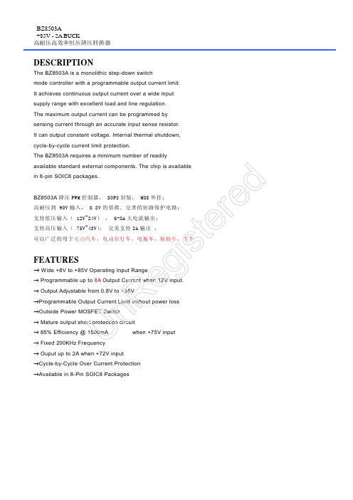
BZ8503A +85V - 2A BUCK 高耐压高效率恒压降压转换器
UnRegistered
BZ8503A +85V - 2A BUCK 高耐压高效率恒压降压转换器
UnRegistered A PPLICATION and PCB reference: 1. Put input capacitor close to NCM0350HV and larger than 100uF or 200uF if over 60V input. 尽量把输入电容靠近芯片输入脚,容量不小于 100uF,如输入电压超过 70V,最好在输入对 GND 加 80V 的 TVS 管,防止 过冲. 2. Put Schottky diode close to SW and GND pin of chip, choose better heat-sink package like SMB or SMC. 尽量把肖特基二极管靠近芯片的 SW 脚与 GND,选择 SMB 或 SMC 等散热好的封装.电流耐压都要有 20%以上的 余量. 3. Choose high efficiency inductor, like the Iron-silicon-aluminum, or some SMT inductors. 尽量选择材质好点的贴片电感或铁硅铝电感.标称电流相对实际电流要有 50%的余量. 4. The external NMOS, choose the Vds value 20V higher than the input volage at least.
R ®Outside Power MOSFET Switch n ® Mature output short protection circuit U ® 85% Efficiency @ 1500mA (Vo=5V) when +75V input
2018年创维43x5配置-范文模板 (13页)
本文部分内容来自网络整理,本司不为其真实性负责,如有异议或侵权请及时联系,本司将立即删除!== 本文为word格式,下载后可方便编辑和修改! ==创维43x5配置篇一:创维电视无线网卡使用设置创维电视无线网卡使用设置BL-LW06-AR / BL-LW06-1R / BL-LW06-ARS / BL-LW06-3R / 网卡使用:此型号网卡支持创维部分网络电视。
如果您是使用在创维电视上,则直接插上电视的USB 接口。
识别后就可以直接使用。
1.打开电视,把无线网卡连接电视机USB接口2.选择酷开设置→网络设置→无线网络a.自动查找→选择自已无线网络用户名,进行连接b.手动连接→输入无线网络用户名和密码,进行连接c.自动获取IP→选择以后,自动搜索IP,并连接网络d.手动设置IP→输入IP信息,进行连接3.连接正常以后,屏幕右上方显示连接信息(IP地址,DNS地址,MAC地址等)创维新款的E60,E80,K06电视无线设置步骤如下:酷开设置-无线网络-显示信号-开放系统/网络密码/WPA密钥;当路由器未加密时选“开放系统”,当路由器为WEP加密时选“网络密码”进入填写密码,当无线路由器为WPA或WPA-PSK加密时选“WPA密钥”进行密码输入。
(注意:无线路由器的“开放系统”与电视机的“开放系统”意思不同,电视的开放系统表示无线网络没有加密码,而无线路由WEP加密设置中的开放系统是指一种网络认证方式,电视机的表述有误。
)常见问题:1:插上网卡后,电视未发现网卡;解决方法:1. 重新插拨一下网卡,确保插好网卡。
2. 更换USB 接口,即将网卡插在另一个接口。
3. 如果还是没有找到,则可能USB接口出现问题,将网卡插上电脑上测试网卡是否有问题。
详细请参照如下电脑设置。
2:找到了无线信号,却连接不上。
问题解析:可能是路由器或AP(无线信号设备)的问题,或者加密问题。
解决方法:1. 将路由器断下电; 2. 复位下路由器,重新设置下; 3. 取消加密或更换其它的加密方式。
BZX85C12中文资料
©2004 Fairchild Semiconductor Corporation
元器件交易网
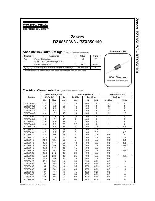
Zeners BZX85C3V3 - BZX85C100
Electrical Characteristics (Continued) T =25°C unless otherwise noted
TA=25°C unless otherwise noted
Zener Voltage (Note 1) IZ mA 80 60 60 50 45 45 45 35 35 35 25 25 25 20 20 20 15 15 15 10 10 10 8 8 8 8 6 6 4 4
Zener Impedance ZZ @ IZ ( Ω) 20 15 15 13 13 10 7 4 3.5 3 5 5 7 8 9 10 15 15 20 24 25 25 30 30 35 40 45 50 90 115 ZZK @ IZK (Ω ) 400 500 500 500 600 500 400 300 300 200 200 200 200 300 350 400 500 500 500 600 600 600 750 1000 1000 1000 1000 1000 1500 1500
元器件交易网
Zenersners BZX85C3V3 - BZX85C100
Absolute Maximum Ratings *
Symbol PD Parameter Power Dissipation @ TL ≤ 50°C, Lead Length = 3/8” Derate above 50°C TJ, TSTG Operating and Storage Temperature Range
是德科技 L4433A 双 四 4x8 干簧矩阵 技术资料说明书

引言双/四4x8 矩阵提供高性能信号开关功能Keysight L4433A 是一款符合LXI C 类标准的高速干簧继电器矩阵。
凭借小巧的外形和出色的以太网连通性,它可以放置在应用需要的任何地方。
Keysight L4433A 在您的被测器件(DUT) 和测试设备之间提供一条灵活的连接路径,可以把不同的仪器同时连接到被测器件的多个点上。
这款仪器可配置为2 线或1 线矩阵,增加了交叉点的数量。
通过模拟总线连接器,可以把多个矩阵结合起来,创建一个更大规模的矩阵。
使用这款LXI 仪器,您将能利用以太网连接、仪表网络服务器、标配软件驱动程序等功能特性的全部优势。
LXI 标准已获得许多厂商的支持,因此可以加快测试的集成和开发,降低测试成本。
图1. L4433A 双l四4 x 8 干簧矩阵。
为灵活可靠的连接提供开关功能L4433A 拥有一个完整的交叉点矩阵,可以把任何行连接到任何列上。
这提供了一种方便的方式,使多部测试仪器可以连接到被测器件的多个点上。
高速干簧继电器则可以保证快速响应。
矩阵开关中的每个交叉点都为测量提供了两条线,一条为高,一条为低。
如果用户愿意,也可以把 L4433A 配置成 1 线矩阵,把交叉点数量增加到 128个。
L4433A 在每一列上还配有浪涌电阻器,进一步增强保护能力。
可以使用模拟总线连接器创建更大规模的矩阵,扩展矩阵容量;也可以简便地把矩阵连接到数字万用表等外部测量设备上。
序列功能定义了开关闭合和控制功能,可以根据不同的开关设置简便地改变顺序。
用户可以指定一个序列并命名,而后便可以使用这个自定义的名称执行此序列。
外部触发功能可以简便地计时和同步开关闭合和打开。
L4433A 还包括一个继电器计数器,用于监测及帮助您预测继电器何时接近使用寿命。
简便地把信号路由到外部数字万用表L4433A 开关支持高达±150 V 和0.5 A 的信号,因此无需外部信号调理。
利用模拟总线连接器,可以简便地把矩阵开关信号路由到外部设备。
EC43中空型编码器
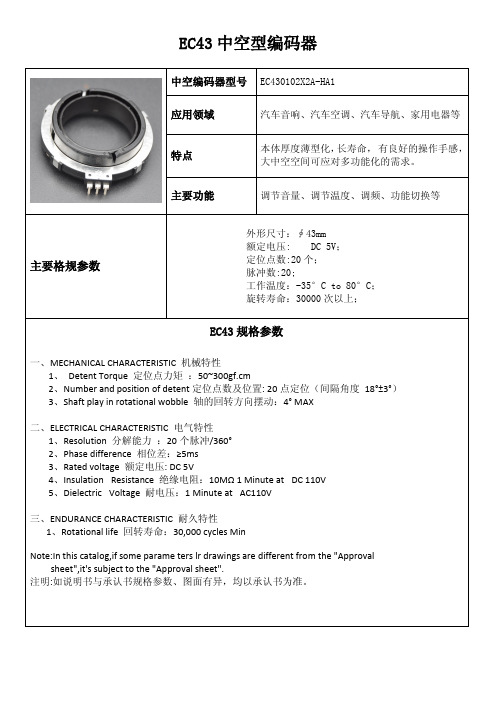
EC43中空型编码器中空编码器型号EC430102X2A-HA1应用领域汽车音响、汽车空调、汽车导航、家用电器等特点本体厚度薄型化,长寿命,有良好的操作手感,大中空空间可应对多功能化的需求。
主要功能调节音量、调节温度、调频、功能切换等主要格规参数外形尺寸:∮43mm额定电压:DC5V;定位点数:20个;脉冲数:20;工作温度:-35°C to80°C;旋转寿命:30000次以上;EC43规格参数一、MECHANICAL CHARACTERISTIC机械特性1、Detent Torque定位点力矩:50~300gf.cm2、Number and position of detent定位点数及位置:20点定位(间隔角度18°±3°)3、Shaft play in rotational wobble轴的回转方向摆动:4°MAX二、ELECTRICAL CHARACTERISTIC电气特性1、Resolution分解能力:20个脉冲/360°2、Phase difference相位差:≥5ms3、Rated voltage额定电压:DC5V4、Insulation Resistance绝缘电阻:10MΩ1Minute at DC110V5、Dielectric Voltage耐电压:1Minute at AC110V三、ENDURANCE CHARACTERISTIC耐久特性1、Rotational life回转寿命:30,000cycles MinNote:In this catalog,if some parame ters lr drawings are different from the"Approval sheet",it's subject to the"Approval sheet".注明:如说明书与承认书规格参数、图面有异,均以承认书为准。
艾为产品介绍PDF

TDD-Noise-输入干扰
湘海电子有限公司Http:\\
远端地与近端地的不一致导致了输入干扰
Tankertanker Design
音乐功放系列全线升级
型号 AW8145CSR AW8155FCR AW8120FCR AW8010AFCR AW8090ACOR AW8110CSR AW8188TQR 特性 防破音,超低EMI AB/D自由切换的第二代音乐功放 AB/D自由切换的第二代音乐功放 超低EMI AB类功放 防破音,超低EMI D类双声道立体声,防破音,超低EMI 封装 FC9 FC9 FC9 FC9 COL9 CSP9 16-Pin TQFN
AW3210典型应用图1
Tankertanker Design
AW3210典型应用图2
Tankertanker Design
AW3210典型应用图3
Tankertanker Design
射频系列
型号 AW5007STR 特性 低噪声放大器 封装 SOT363-6L
华硕主板

数字家庭主板M2NDH-支持AMD®SocketAM2Athlon64FX/Athlo64X2/Athlon64/Sempron -AMDLive!™Ready-强大扩充能力:1xPCI-Ex16、2xPCI-E、3xPCI-华硕WiFi-APSolo-华硕DHRemote™-华硕MP3-In™-华硕Q-Connector-高保真音频中央处理器支持AMD®SocketAM2Athlon64FX/Athlo64X2/Athlon64/Sempron 支持AMDCool'n'Quiet™技术AMD64架构,同时兼容32位和64位计算AMDLive!™Ready芯片组NVIDIAnForce®430MCP前端总线2000/1600MT/s内存双通道内存架构4x240-pinDIMM内存插槽,支持最大容量高达8GB的DDR2800/667/533ECC和non-ECC、un-buffered内存扩充插槽1xPCI-Expressx16插槽2xPCI-Expressx1插槽3xPCI2.2插槽存储装置/RAID-1xUltraDMA133/100/66/33-4xSerialATA3.0Gb/s-NVIDIAMediaShield™RAID通过SerialA TA设备支持RAID0、1、0+1、5和JBOD网络功能NVIDIAnForce®430内建GigabitMAC,支持externalAttansicPHY无线局域网:54MbpsIEEE802.11b/g(华硕WiFi-APSolo)音频功能ADI6声道高保真音频CODEC背板S/PDIF数字音频输出USB高达8个USB2.0/1.1接口M2N-VMDH-AMDSocketAM2-NVIDIAGeForce6100/nForce430-双通道DDR2800/667/533-1xPCIExpressx16+1xPCIExpressx1+2xPCI-双VGA:DVI-D和D-Sub-8声道高保真音频-2x1394a接口中央处理器支持AMD®SocketAM2Athlon64X2/Athlon64FX/Athlon64/Sempro nAMDCool'n'Quiet™技术AMD64架构,兼容32位和64位计算AMDLive!™Ready芯片组NVIDIAGeForce6100/nForce430前端总线2000/1600MT/s 内存双通道内存架构4x240-pinDIMM插槽,支持最大容量为8GB的DDR2800/667/533non-ECC,un-buffered内存显卡集成GeForce6100GPU高清晰视频处理,最高分辨率可达1920x1440(@75Hz)支持RGB显示;UXGA1600x1200(@60Hz)支持DVI-D显示支持双VGA输出:DVI-D和RGB注意:DVI-D不能用来输出RGB信号至CRT。
FH8523中文数据手册
目录
1、概述 ..........................................................................................................................................................4 1.1 基本特征 ..............................................................................................................................................4 1.2 FH8523 系统框图 .............................................................................................................................5
图形目录
图表 1 FH8523 系统框图 ................................................................................................................................ 5 图表 2 FH8523 管脚分配 ................................................................................................................................ 9 图表 3 时钟参考电路 .................................................................................................................................... 13 图表 4 复位参考电路 .................................................................................................................................... 14 图表 5DAC 参考电路.................................................................................................................................... 14 图表 6 FH8523 封装尺寸 .............................................................................................................................. 17
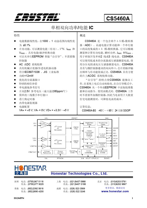
CS5463A中文资料手册pdf
гомдустру roduction EFPAU TEST NO说明书
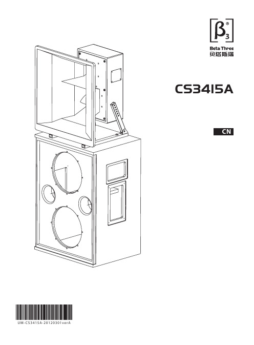
感谢您购买 产品!请仔细阅读本手册,它将帮助你妥善设置并运行您的系统,使其发挥卓越的性能。
并保留这些说明以供日后参照。
警告:为了降低火灾与电击的风险,请不要将产品暴露在雨中或潮湿环境中。
警告:为了降低电击的风险,非专业人士请勿擅自拆卸该系统。
仅供专业人士操作。
等边三角形中的闪电标记,用以警示用户该部件为非绝缘体,系统内部存在着电压危险,电压。
可能足以引起触电。
可能足以引起触电如系统标有带惊叹号的等边三角形,则是为提示用户严格遵守本用户指南中的操作与维护规定。
注意:请勿对系统或附件作擅自的改装。
未经授权擅自改装将造成安全隐患。
警告:燃不得将明火源(如点的蜡烛)放在器材上面。
1. 请先阅读本说明。
2. 保留这些说明以供日后参照。
3. 注意所有警告信息。
4. 遵守各项操作指示。
5. 不要在雨水中或潮湿环境中使用本产品。
6. 不要将产品靠近热源安装,例如暖气管、加热器、火炉或其它能产生热量的装置(包括功放机 )。
7. 不要破坏极性或接地插头的安全性设置。
如果提供的插头不能插入插座,则应当请专业人员更换插座。
8. 保护好电源线和信号线,不要在上面踩踏或拧在一起(尤其是插头插座及穿出机体以外的部分 )。
9. 使用厂商规定及符合当地安全标准的附件。
10.雷电或长时间不使用时请断电以防止损坏产品。
12. 不要让物体或液体落入产品内——它们可能引起火灾或触电。
13. 请注意产品外罩上的相关安全标志。
. 仅与厂商指定或与电器一同售出的推车、架子、三脚架、支架或桌子一起使用。
推动小车/电器时,应谨防翻倒。
11注意事项产品的安装调试须由专业人士操作。
在使用非本厂规定的吊装件时,要保证结构的强度并符合当地的安全规范。
警告:1扬声器及扬声器系统的产品有限保修期为自正式购买日起的3年。
由于用户不合理的应用而导致音圈烧毁或纸盆损坏等故障,不包含于产品保修项目。
产品吊附件(包括音箱装配五金件和吊挂配件)的有限保修期为自正式购买日起的1年。
莫萨 UC-8540 系列双核 Cortex-A7 1GHz 火车到地面计算机说明书

UC-8540SeriesArm Cortex-A7dual-core1GHz train-to-ground computers with2mini PCIe expansion slots for wireless modulesFeatures and Benefits•Supports1WWAN connection with2SIM card slots•Supports1WLAN(IEEE802.11b/g/n/ac)connection•Single-panel I/O design for reduced installation space and easiermaintenance•Front-side access panel for easy maintenance•Isolated24to110VDC power input with power-ignition function suitable forvehicle applications•EN50155Tx(-40to70°C)operating temperature for harsh environments•Complies with all EN50155mandatory test items1•5-year warrantyCertificationsIntroductionMoxa’s UC-8540is an innovative computing platform designed specifically for transportation applications.Its single-sided I/O design is ideal for vehicle applications,which typically do not have enough room for installing communication devices.Front-side access makes it easy to install or change SIM cards and wiring ers can install or change wireless modules,mSATA cards,and the RTC battery from the top or the bottom for easy maintenance.The UC-8540has1miniPCIe slot with USB signal to support a4G/LTE module,and1slot with PCIe/USB signal to support a Wi-Fi module.The4G/ LTE module has two SIM card slots,which can be used to enable redundant cellular network communications or geo-fencing SIM card selection by leveraging the built-in MIRF2.0,a Moxa device remote-management platform with wireless management.The UC-8540can be used as a communication-centric computing platform in applications such as vehicle-to-ground communication gateway, TCMS T2G(train-to-ground)gateway,mobile condition monitoring unit,Ethernet Consist Network T2G gateway,and onboard wireless automated fare collection unit.2The UC-8540uses an open platform based on Debian8with Linux kernel4.1,allowing solution providers to manage software packages via Debian’s APT(advanced packaging tools),or develop software applications with Moxa’s API Library and GNU C Library.1.This product is suitable for rolling stock railway applications,as defined by the EN50155standard.For a more detailed statement,click here:/doc/specs/EN_50155_Compliance.pdf2.Wireless modules are sold separately.Please contact a Moxa sales representative for details.AppearanceSpecificationsComputerCPU Armv7Cortex-A7dual-core1GHzStorage Pre-installed8GB eMMCSupported OS Linux Debian8(Linux kernel v4.1)System Memory Pre-installed1GB DDR3LStorage Slot mSATA slots x1,internal mini-PCIe socketComputer InterfaceExpansion Slots mPCIe slot x2Ethernet Ports Auto-sensing10/100/1000Mbps ports(M12X-coded)x2 Cellular Antenna Connector QMA x2USB3.0USB3.0hosts x1,type-A connectorsWi-Fi Antenna Connector QMA x3Serial Ports RS-232/422/485ports x1,software selectable(DB9male) Number of SIMs2Console Port RS-232(TxD,RxD,GND),4-pin header output(115200,n,8,1) GPS Antenna Connector TNC x1SIM Format MicroInput/Output InterfaceButtons Reset buttonLED IndicatorsSystem Power x1System Ready x1Programmable x1LAN2per port(10/100/1000Mbps)Serial2per port(Tx,Rx)Wireless Signal Strength Cellular/Wi-Fi x6Serial SignalsRS-232TxD,RxD,RTS,CTS,DTR,DSR,DCD,GNDRS-422Tx+,Tx-,Rx+,Rx-,GNDRS-485-2w Data+,Data-,GNDRS-485-4w Tx+,Tx-,Rx+,Rx-,GNDGPS InterfaceHeading Accuracy0.3degreesIndustrial Protocols NMEA0183,version4.0(V2.3or V4.1configurable),UBX,RTCM Receiver Types72-channel u-blox M8engineTime Pulse0.25Hz to10MHzVelocity Accuracy0.05msPower ParametersInput Current 1.66A@24VDC,0.36A@110VDCInput Voltage24to110VDCPower Connector M12A-coded4-pin male connectorPower Consumption40W(max.)Physical CharacteristicsProtection UC-8540-T-CT-LX:PCB conformal coatingDimensions(with ears)190x120x125mm(7.46x4.72x4.92in)Dimensions(without ears)160x120x120mm(6.30x4.72x4.72in)Housing MetalInstallation Wall mountingIP Rating IP40Weight Product only:1,600g(3.53lb) Environmental LimitsAmbient Relative Humidity5to95%(non-condensing)Operating Temperature Standard Models:-25to55°C(-13to131°F)Wide Temp.Models:-40to70°C(-40to158°F) Storage Temperature(package included)-40to85°C(-40to185°F)Standards and CertificationsEMC EN55032/35EMI CISPR32,FCC Part15B Class AEMS IEC61000-4-2ESD:Contact:6kV;Air:8kVIEC61000-4-3RS:80MHz to1GHz:20V/mIEC61000-4-4EFT:Power:2kV;Signal:2kVIEC61000-4-5Surge:Power:2kV;Signal:2kVIEC61000-4-6CS:10VIEC61000-4-8PFMFRailway EN50121-4,EN50155Railway Fire Protection EN45545-2Safety EN62368-1,IEC62368-1Shock IEC60068-2-27,IEC61373,EN50155 Vibration IEC60068-2-64,IEC61373,EN50155 DeclarationGreen Product RoHS,CRoHS,WEEEWarrantyWarranty Period5yearsDetails See /warrantyPackage ContentsDevice1x UC-8540Series computer Documentation1x quick installation guide1x warranty cardCable1x4-pin header to DB9console cableDimensionsOrdering InformationModel Name CPU Antenna Connector Type Operating Temp.Conformal Coating UC-8540-LX Armv7Cortex-A7dual-core1GHz QMA-25to55°C–UC-8540-T-LX Armv7Cortex-A7dual-core1GHz QMA-40to70°C–UC-8540-T-CT-LX Armv7Cortex-A7dual-core1GHz QMA-40to70°C✓Accessories(sold separately)Wi-Fi Wireless ModulesUC-8500-WLAN33-Q-AC3transmitter3receiver Wi-Fi card module,3QMA connectors with cablesUC-8500-WLAN33-Q-AC-TELEC2transmitter2receiver Wi-Fi card module with TELEC certification,2QMA connectors with cables Cellular Wireless ModulesUC-8500-4GCat6-Q-NAMEU LTE Cat.6module for North America and Europe,2QMA connectors with cables,-40to60°Coperating temperatureUC-8500-4GCat6-Q-APAC LTE Cat.6module for North America and Europe,2QMA connectors with cables,-40to60°Coperating temperaturePower AdaptersPWR-24270-DT-S1Power adapter,input voltage90to264VAC,output voltage24V with2.5A DC loadPower CordsPWC-C7AU-2B-183Power cord with Australian(AU)plug,2.5A/250V,1.83mPWC-C7CN-2B-183Power cord with three-prong China(CN)plug,2.5A/250V,1.83mPWC-C7EU-2B-183Power cord with Continental Europe(EU)plug,2.5A/250V,1.83mPWC-C7UK-2B-183Power cord with United Kingdom(UK)plug,2.5A/250V,1.83mPWC-C7US-2B-183Power cord with United States(US)plug,10A/125V,1.83mCablesCBL-F9DPF1x4-BK-100Console cable with4-pin connector,1m©Moxa Inc.All rights reserved.Updated Feb04,2021.This document and any portion thereof may not be reproduced or used in any manner whatsoever without the express written permission of Moxa Inc.Product specifications subject to change without notice.Visit our website for the most up-to-date product information.。
BZX84C18-V中文资料

Document Number Small Signal Zener DiodesFeatures•These diodes are also available in other case styles and other configurationsincluding: the SOD-123 case with type designation BZT52 series, the dual zenerdiode common anode configuration in the SOT-23case with type designation AZ23 series and the dual zener diode common cathode configuration in the SOT-23 case with type designation DZ23series.•The Zener voltages are graded according to the international E 24 standard. Standard Zener volt-age tolerance is ± 5 %. Replace "C" with "B" for ± 2 % tolerance.•Silicon Planar Power Zener Diodes •Lead (Pb)-free component•Component in accordance to RoHS 2002/95/EC and WEEE 2002/96/ECWeight: approx. 8.8 mgPackaging Codes/Options:GS18 / 10 k per 13" reel (8 mm tape), 10 k/box GS08 / 3 k per 7" reel (8 mm tape), 15 k/boxAbsolute Maximum RatingsT amb = 25°C, unless otherwise specified1) Device on fiberglass substrate, see layout.Thermal CharacteristicsT amb = 25°C, unless otherwise specified1)Device on fiberglass substrate, see layout.ParameterT est condition Symbol Value Unit Power dissipationP tot300 1)mWParameterTest condition Symbol Value Unit Thermal resistance junction to ambient air R thJA 420 1)°C/W Junction temperature T j 150°C Storage temperature rangeT S- 65 to + 150°CElectrical CharacteristicsPartnumber MarkingCodeZenerVoltageRangeDynamic Resistance T estCurrentTemp.Coefficientof ZenerVoltageTestCurrentReverse LeakageCurrentV Z @ I ZT1r zj @ I ZT1r zj @ I ZT2I ZT1αVZ @ I ZT1I ZT2I R@ V R VΩmA10-4/°C mAµA Vmin max min maxBZX84C2V4-V Z11 2.2 2.670 (≤100)2755-9.0-4.01501 BZX84C2V7-V Z12 2.5 2.975 (≤100)300 (≤600)5-9.0-4.01201 BZX84C3V0-V Z13 2.8 3.280 (≤95)325 (≤600)5-9.0-3.01101 BZX84C3V3-V Z14 3.1 3.585 (≤95)350 (≤600)5-8.0-3.0151 BZX84C3V6-V Z15 3.4 3.885 (≤90)375 (≤600)5-8.0-3.0151 BZX84C3V9-V Z16 3.7 4.185 (≤90)400 (≤600)5-7.0-3.0131 BZX84C4V3-V Z174 4.680 (≤90)410 (≤600)5-6.0-1.0131 BZX84C4V7-V Z1 4.4550 (≤80)425 (≤500)5-5.0+2.0132 BZX84C5V1-V Z2 4.8 5.440 (≤60)400 (≤480)5-3.0+4.0122 BZX84C5V6-V Z3 5.2615 (≤40)80 (≤400)5-2.0+6.0112 BZX84C6V2-V Z4 5.8 6.6 6.0 (≤10)40 (≤150)5-1.0+7.0134 BZX84C6V8-V Z5 6.47.2 6.0 (≤15)30 (≤80)5+2.0+7.0124 BZX84C7V5-V Z677.9 6.0 (≤15)30 (≤80)5+3.0+7.0115 BZX84C8V2-V Z77.78.7 6.0 (≤15)40 (≤80)5+4.0+7.010.75 BZX84C9V1-V Z88.59.6 6.0 (≤15)40 (≤100)5+5.0+8.010.56 BZX84C10-V Z99.410.68.0 (≤20)50 (≤150)5+5.0+8.010.27 BZX84C11-V Y110.411.610 (≤20)50 (≤150)5+5.0+9.010.18 BZX84C12-V Y211.412.710 (≤25)50 (≤150)5+6.0+9.010.18 BZX84C13-V Y312.414.110 (≤30)50 (≤170)5+7.0+9.010.18 BZX84C15-V Y413.815.610 (≤30)50 (≤200)5+7.0+9.010.050.7 V Znom.BZX84C16-V Y515.317.110 (≤40)50 (≤200)5+8.0+9.510.050.7 V Znom.BZX84C18-V Y616.819.110 (≤45)50 (≤225)5+8.0+9.510.050.7 V Znom.BZX84C20-V Y718.821.215 (≤55)60 (≤225)5+8.0+1010.050.7 V Znom.BZX84C22-V Y820.823.320 (≤55)60 (≤250)5+8.0+1010.050.7 V Znom.BZX84C24-V Y922.825.625 (≤70)60 (≤250)5+8.0+1010.050.7 V Znom.BZX84C27-V Y1025.128.925 (≤80)65 (≤300)2+8.0+100.50.050.7 V Znom.BZX84C30-V Y11283230 (≤80)70 (≤300)2+8.0+100.50.050.7 V Znom.BZX84C33-V Y12313535 (≤80)75 (≤325)2+8.0+100.50.050.7 V Znom.BZX84C36-V Y13343835 (≤90)80 (≤350)2+8.0+100.50.050.7 V Znom.BZX84C39-V Y14374140 (≤130)80 (≤350)2+10+120.50.050.7 V Znom.BZX84C43-V Y15404645 (≤150)85 (≤375)2+10+120.50.050.7 V Znom.BZX84C47-V Y16445050 (≤170)85 (≤375)2+10+120.50.050.7 V Znom.BZX84C51-V Y17485460 (≤180)85 (≤400)2+10+120.50.050.7 V Znom.BZX84C56-V Y18526070 (≤200)100 (≤425)2+9.0+110.50.050.7 V Znom.BZX84C62-V Y19586680 (≤215)100 (≤450)2+9.0+120.50.050.7 V Znom.BZX84C68-V Y20647290 (≤240)150 (≤475)2+10+120.50.050.7 V Znom.BZX84C75-V Y21707995 (≤255)170 (≤500)2+10+120.50.050.7 V Znom. Document Number 85763Document Number Electrical CharacteristicsPartnumberMarking CodeZener Voltage Range Dynamic ResistanceTest CurrentT emp. Coefficient of Zener Voltage T est CurrentReverse LeakageCurrentV Z @ I ZT1r zj @ I ZT1r zj @ I ZT2I ZT1αVZ @ I ZT1I ZT2I R @ V R V ΩmA10-4/°C mAµAVminmax min max BZX84B2V4-V Z50 2.35 2.4570 (≤100)2755-9-41501BZX84B2V7-V Z51 2.65 2.7575 (≤100)300 (≤600)5-9-41201BZX84B3V0-V Z52 2.94 3.0680 (≤95)325 (≤600)5-9-31101BZX84B3V3-V Z53 3.23 3.3785 (≤95)350 (≤600)5-8-3151BZX84B3V6-V Z54 3.53 3.6785 (≤90)375 (≤600)5-8-3151BZX84B3V9-V Z55 3.82 3.9885 (≤90)400 (≤600)5-7-3131BZX84B4V3-V Z56 4.21 4.3980 (≤90)410 (≤600)5-6-1131BZX84B4V7-V Z57 4.61 4.7950 (≤80)425 (≤500)5-52132BZX84B5V1-V Z585 5.240 (≤60)400 (≤480)5-34122BZX84B5V6-V Z59 5.49 5.7115 (≤40)80 (≤400)5-26112BZX84B6V2-V Z60 6.08 6.32 6.0 (≤10)40 (≤150)5-17134BZX84B6V8-V Z61 6.66 6.94 6.0 (≤15)30 (≤80)527124BZX84B7V5-V Z627.357.65 6.0 (≤15)30 (≤80)537115BZX84B8V2-V Z638.048.36 6.0 (≤15)40 (≤80)54710.75BZX84B9V1-V Z648.929.28 6.0 (≤15)40 (≤100)55810.56BZX84B10-V Z659.810.28.0 (≤20)50 (≤150)55810.27BZX84B11-V Z6610.811.210 (≤20)50 (≤150)55910.18BZX84B12-V Z6711.812.210 (≤25)50 (≤150)56910.18BZX84B13-V Z6812.713.310 (≤30)50 (≤170)57910.18BZX84B15-V Z6914.715.310 (≤30)50 (≤200)57910.050.7 V Znom.BZX84B16-V Z7015.716.310 (≤40)50 (≤200)589.510.050.7 V Znom.BZX84B18-V Z7117.618.410 (≤45)50 (≤225)589.510.050.7 V Znom.BZX84B20-V Z7219.620.415 (≤55)60 (≤225)581010.050.7 V Znom.BZX84B22-V Z7321.622.420 (≤55)60 (≤250)581010.050.7 V Znom.BZX84B24-V Z7423.524.525 (≤70)60 (≤250)581010.050.7 V Znom.BZX84B27-V Z7526.527.525 (≤80)65 (≤300)28100.50.050.7 V Znom.BZX84B30-V Z7629.430.630 (≤80)70 (≤300)28100.50.050.7 V Znom.BZX84B33-V Z7732.333.735 (≤80)75 (≤325)28100.50.050.7 V Znom.BZX84B36-V Z7835.336.735 (≤90)80 (≤350)28100.50.050.7 V Znom.BZX84B39-V Z7938.239.840 (≤130)80 (≤350)210120.50.050.7 V Znom.BZX84B43-V Z8042.143.945 (≤150)85 (≤375)210120.50.050.7 V Znom.BZX84B47-V Z8146.147.950 (≤170)85 (≤375)210120.50.050.7 V Znom.BZX84B51-V Z82505260 (≤180)85 (≤400)210120.50.050.7 V Znom.BZX84B56-V Z8354.957.170 (≤200)100 (≤425)29110.50.050.7 V Znom.BZX84B62-V Z8460.863.280 (≤215)100 (≤450)29120.50.050.7 V Znom.BZX84B68-V Z8566.669.490 (≤240)150 (≤475)210120.50.050.7 V Znom.BZX84B75-VZ8673.576.595 (≤255)170 (≤500)210120.50.050.7 V Znom. Document Number 85763Typical Characteristics (Tamb = 25 °C unless otherwise specified)Figure 1. Forward characteristics Figure 2. Admissible Power Dissipation vs. Ambient Temperature Figure3. Pulse Thermal Resistance vs. Pulse Duration1811418115Figure 4. Dynamic Resistance vs. Zener CurrentFigure 5. Capacitance vs. Zener VoltageFigure6. Dynamic Resistance vs. Zener Current1811718118Document Number Figure 7. Dynamic Resistance vs. Zener CurrentFigure 8. Thermal Differential Resistance vs. Zener Voltage Figure9. Dynamic Resistance vs. Zener Voltage18120Figure 10. Temperature Dependence of Zener Voltage vs. ZenerVoltageFigure 11. Change of Zener Voltage vs. Junction TemperatureFigure 12. Temperature Dependence of Zener Voltage vs. ZenerVoltage18124°C18136 Document Number 85763Figure 13. Change of Zener Voltage vs. Junction TemperatureFigure 14. Change of Zener voltage from turn-on up to the point ofthermal equilibrium vs. Zener voltageFigure 15. Change of Zener voltage from turn-on up to the point ofthermal equilibrium vs. Zener voltage181261813718138Document Number Figure 16. Breakdown CharacteristicsFigure17. Breakdown Characteristics1811118112 Document Number 85763Layout for R Theta;JA testThickness: Fiberglass 0.059 in. (1.5 mm)Copper leads 0.012 in. (0.3 mm)Figure18. Breakdown Characteristics18113Package Dimensions in mm (Inches)Document Number Ozone Depleting Substances Policy StatementIt is the policy of Vishay Semiconductor GmbH to1.Meet all present and future national and international statutory requirements.2.Regularly and continuously improve the performance of our products, processes, distribution and operatingsystems with respect to their impact on the health and safety of our employees and the public, as well as their impact on the environment.It is particular concern to control or eliminate releases of those substances into the atmosphere which are known as ozone depleting substances (ODSs).The Montreal Protocol (1987) and its London Amendments (1990) intend to severely restrict the use of ODSs and forbid their use within the next ten years. Various national and international initiatives are pressing for an earlier ban on these substances.Vishay Semiconductor GmbH has been able to use its policy of continuous improvements to eliminate the use of ODSs listed in the following documents.1.Annex A, B and list of transitional substances of the Montreal Protocol and the London Amendmentsrespectively2.Class I and II ozone depleting substances in the Clean Air Act Amendments of 1990 by the EnvironmentalProtection Agency (EPA) in the USA3.Council Decision 88/540/EEC and 91/690/EEC Annex A, B and C (transitional substances) respectively. Vishay Semiconductor GmbH can certify that our semiconductors are not manufactured with ozone depleting substances and do not contain such substances.We reserve the right to make changes to improve technical designand may do so without further notice.Parameters can vary in different applications. All operating parameters must be validated for each customer application by the customer. Should the buyer use Vishay Semiconductors products for any unintended or unauthorized application, the buyer shall indemnify Vishay Semiconductors against all claims, costs, damages, and expenses, arising out of, directly or indirectly, any claim of personal damage, injury or death associated with such unintended or unauthorized use.Vishay Semiconductor GmbH, P.O.B. 3535, D-74025 Heilbronn, Germany Document Number 85763。
4435a参数

4435a参数4435a参数是一种常用的技术术语,广泛应用于各个领域。
它是指一种特定的参数设置,用于调整和控制某个系统或设备的性能和功能。
在不同的行业和领域中,4435a参数具有不同的含义和应用。
在电子领域中,4435a参数通常用于描述电子元器件的性能和规格。
例如,对于一款电子元器件,4435a参数可以表示其电压、电流、频率等方面的特性。
这些参数对于设计和使用电子设备非常重要,可以帮助工程师们选择合适的元器件,并确保设备的正常运行。
在通信领域中,4435a参数常常用于描述无线通信系统的性能和覆盖范围。
例如,对于一款无线路由器,4435a参数可以表示其传输速率、信号强度、覆盖范围等方面的特性。
这些参数对于用户选择合适的无线设备和优化网络连接非常重要。
在工业控制领域中,4435a参数被广泛应用于调整和控制各种工业设备的性能和运行状态。
例如,对于一台机械设备,4435a参数可以表示其转速、负载、温度等方面的特性。
通过合理设置这些参数,可以提高设备的效率和稳定性,降低故障率和维修成本。
在医疗领域中,4435a参数常常用于描述医疗设备的性能和治疗效果。
例如,对于一种医疗仪器,4435a参数可以表示其功率、频率、治疗时间等方面的特性。
这些参数对于医生选择合适的治疗方案和评估治疗效果非常重要。
总之,4435a参数是一种重要的技术术语,广泛应用于各个领域。
它可以帮助人们了解和控制系统或设备的性能和功能,从而提高工作效率和产品质量。
在不同的行业和领域中,人们需要根据具体的需求和应用场景,合理设置和调整4435a参数,以达到最佳的效果和效益。
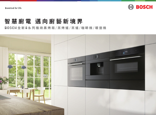
BOSCH全新8系列極緻黑智慧廚電产品介绍说明书
1886年,勞勃 • 博世(Robert Bosch)先生於德國司徒加特創辦了「精密機械和電氣工程車間」,即是今日BOSCH最初的誕生,從精密電機工程起家,並於1929年後轉型為科技家電,以消費者需求及服務為出發點,透過科技成就生活之美。
而創立130多年以來,我們不僅堅持精湛德國工藝高品質的要求,更秉持勞勃 • 博世(Robert Bosch)先生的信念「對客人的承諾 勝過眼前的利益」,繼續為消費者提供創新及完美的科技產品。
“I would rather lose money than trust.”對客人的承諾 勝過眼前的利益 ─ Robert BoschIndex目錄0203BOSCH烤箱歷史事紀Highlights of Cavity Cooking Products199019771962博西家電第一台嵌入式廚房設備誕生推出電子式操作面板烤箱新科技研發擁有高溫自清的烤箱問世2014台灣上市第一台8系列烤箱獨特的環形觸控介面設計全新8系列極緻黑智慧廚電在台上市輕鬆遠端遙控讓生活更便利2014201620232021被譽為廚房最佳幫手三點食物探針功能推出推出智慧烘焙感應技術料理完美上桌推出七合一微波蒸烤爐可蒸煮/烘烤/微波,一機多用0405全新8系列極緻黑智慧廚電Introduction全新升級8系列極緻黑智慧廚電滿足您所有烹調需求健康飲食儼然已成為世界流行趨勢。
全新升級8系列極緻黑智慧廚電,無論您喜歡蒸、烤還是烘焙,一次滿足所有烹調需求。
從入門款的烤箱,到高階具備各種複合智慧功能的烤箱/蒸烤爐/蒸爐,從中式料理到西式甜點,全都交由BOSCH一手包辦,全面升級的烘焙科技以及結合AI人工智慧透過Home Connect智慧物聯提供您所需要的幫助,讓BOSCH健康智慧烤箱為您的料理找到最合適的設定,完美呈現。
0607德式精湛設計Design08Individual Browning全新8系列極緻黑複合式烤箱*烘焙調色盤功能提供千層麵、披薩、麵包卷等食材加強烤色。
BZX84C中文资料

SILIICON PLANAR VOLTAGE REGULATOR DIODEBZX84C2V4 to 75V SOT-23Formed SMD PackageLow voltage general purpose voltage regulator diode ABSOLUTE MAXIMUM RATINGS (T a =25°C)UNIT %Repetitive Peak Forward Current mA Repetitive Peak Working Current mA mW mW °C °CTHERMAL RESISTANCE K/W* Device mounted on a ceramic alumna** Device mounted on an FR5 printed circuit boardELECTRICAL CHARACTERISTICS (T a =25°C unless specified otherwise) Device Temperature DifferentialI R at V RMarkingCoefficient ResistanceS Z (mV/K)rdiff (Ω)µAat I Z test=5mA at I Z test=1mAmin max min max max Max (V)BZX84C2V4 2.20 2.60 -3.560050 1.0Z11BZX84C2V72.50 2.90 -3.560020 1.0Z12BZX84C3V0 2.80 3.20 -3.560010 1.0Z13BZX84C3V3 3.10 3.50 -3.5600 5.0 1.0Z14BZX84C3V6 3.40 3.80 -3.5600 5.0 1.0Z15BZX84C3V9 3.70 4.10-3.56003.0 1.0Z16BZX84C4V34.00 4.60 -3.5600 3.0 1.0Z17BZX84C4V7 4.40 5.00 -3.5 0.2500 3.0 2.0Z1BZX84C5V1 4.80 5.40 -2.7 1.2480 2.0 2.0Z2BZX84C5V6 5.20 6.00 -2.0 2.5400 1.0 2.0Z3BZX84C6V2 5.80 6.60 0.4 3.7150 3.0 4.0Z4BZX84C6V8 6.407.20 1.2 4.580 2.0 4.0Z5BZX84C7V57.007.90 2.5 5.380 1.0 5.0Z6BZX84C8V27.708.70 3.2 6.2800.7 5.0Z7BZX84C9V18.509.60 3.8 7.01000.5 6.0Z8BZX84C109.4010.604.5 8.01500.27.0Z9BZX84C2V4_75V Rev_060506E*** Pulse Test 20ms < tp < 50ms1515152060401015909090801001009595 + 5VALUE max I ZRM Storage Temperature T stg Junction to Ambient*R th (j-a)DESCRIPTIONI FRM Working Voltage Tolerance Power Dissipation upto T a =25ºC SYMBOL *P D ***V Z ( + 5%)(V)at I Z test=5mA Resistance rdiff (Ω)at I Z test=5mA250420300- 65 to +150250Forward Voltage at V F <0.9V at 10mA and <1.5V at 200mAVoltage 150250Differential Working Power Dissipation upto T c =25ºC **P D Junction Temperature T j Pin Configuration1 = A N ODE2 = N C3 =CATHODE12Continental Device India LimitedAn ISO/TS 16949, ISO 9001 and ISO 14001 Certified CompanySILIICON PLANAR VOLTAGE REGULATOR DIODEBZX84C2V4 to 75V SOT-23Formed SMD PackageELECTRICAL CHARACTERISTICS (T a =25°C unless specified otherwise) Device Temperature DifferentialI R at V RMarkingCoefficientResistanceS Z (mV/K)rdiff (Ω)µAat I Z test=5mAat I Z test=1mA min max min max max Max (V)BZX84C1110.4011.60 5.4 9.01500.18Y1BZX84C1211.4012.70 6.0 101500.18Y2BZX84C1312.4014.10 7.0 111700.18Y3BZX84C1513.8015.60 9.2 132000.0510.5Y4BZX84C1615.3017.10 10.4 142000.0511.2Y5BZX84C1816.8019.10 12.4 162250.0512.6Y6BZX84C2018.8021.20 14.4 182250.0514.0Y7BZX84C2220.8023.30 16.4 202500.0515.4Y8BZX84C2422.8025.60 18.4 222500.0516.8Y9at I Z Test=2mA at I Z Test=0.5mABZX84C2725.1028.90 21.4 25.33000.0518.9Y10BZX84C3028.0032.00 24.4 29.43000.0521.0Y11BZX84C3331.0035.00 27.4 33.43250.0523.1Y12BZX84C3634.0038.00 30.4 37.43500.0525.2Y13BZX84C3937.0041.00 33.4 41.23500.0527.3Y14BZX84C4340.0046.00 37.6 46.63750.0530.1Y15BZX84C4744.0050.00 42.0 51.83750.0532.9Y16BZX84C5148.0054.00 46.6 57.24000.0535.7Y17BZX84C5652.0060.00 52.2 63.84250.0539.2Y18BZX84C6258.0066.00 58.8 71.64500.0543.4Y19BZX84C6864.0072.00 65.6 79.84750.0547.6Y20BZX84C7570.0079.0073.4 88.65000.0552.5Y21BZX84C2V4_75V Rev_060506E*** Pulse Test 20ms < tp < 50ms2002152402551301501701808080908025303070at I Z test=5mA at I Z test=5mA max at I Z test=2mAat I Z Test=2mA4045555520Resistance ***V Z ( + 5%)rdiff (Ω)(V)Forward Voltage at V F <0.9V at 10mA and <1.5V at 200mAWorking Differential Voltage Pin Configuration1 = A N ODE2 = N C3 =CATHODE12BZX84C2V4 to 75V SOT-23Formed SMD PackageSOT-23 Package Reel InformationReel specification for W" Packing (13" reel)BZX84C2V4_75V Rev_060506ESOT-23 Formed SMD PackageTape Specification for SOT-23 Surface Mount DeviceS O T -23 T &R3K /reel 10K /reel136 g m /3K p c s 415 g m /10K p c s3" x 7.5" x 7.5"9" x 9" x 9"13" x 13" x 0.5"12 K 51 K 10 K17" x 15" x 13.5"19" x 19" x 19"17" x 15" x 13.5"192 K 408 K 300 K12 k g s 28 k g s 16 k g sPACKAGEN e t W e i g h t /Q t y DetailsS T A N D A R D PACKI N N E R C A R T O N B O XQ t y O U T E R C A R T O N B O XQ t y G r W t SizeSizePacking Detail±0.0114.47.9 – 10.9T R A I L E RF I X I N GT A P EL E A D E R9.2±0.5MAXNOTES:No. of Devices8mm Tape Size of Reel 330 mm (13")10,000 Pcs 8mm Tape Size of Reel 180 mm (7")3,000 Pcs1.The bandolier of 330 mm reel contains at least 10,000 devices.2.The bandolier of 180 mm reel contains at least 3,000 devices.3.No more than 0.5% missing devices / reel. 50 empty compartments for 330 mm reel.15 empty compartments for 180 mm reel.4.Three consecutive empty places might be found provided this gap is followed by 6 consecutive devices.5.The carrier tape (leader) starts with at least 75 empty positions (equivalent to 330 mm).In order to fix the carrier tape a self adhesive tape of 20 to 50 mm is applied. At the end of the bandolier at least 40 empty positions (equivalent to 160 mm) are there.3.15Customer Notes BZX84C2V4 to 75VSOT-23Formed SMD Package1. CDIL Semiconductor Devices are RoHS compliant, customers are requested to pleasedispose as per prevailing Environmental Legislation of their Country.2. In Europe, please dispose as per EU Directive 2002/96/EC on Waste Electrical andElectronic Equipment (WEEE).BZX84C2V4_75V Rev_060506E DisclaimerThe product information and the selection guides facilitate selection of the CDIL's Semiconductor Device(s)best suited for application in your product(s)as per your requirement.It is recommended that you completely review our Data Sheet(s)so as to confirm that the Device(s)meet functionality parameters for your application.The information furnished in the Data Sheet and on the CDIL Web Site/CD are believed to be accurate and reliable.CDIL however,does not assume responsibility for inaccuracies or incomplete information.Furthermore,CDIL does not assume liability whatsoever,arising out of the application or use of any CDIL product;neither does it convey any license under its patent rights nor rights of others. These products are not designed for use in life saving/support appliances or systems.CDIL customers selling these products(either as individual Semiconductor Devices or incorporated in their end products),in any life saving/support appliances or systems or applications do so at their own risk and CDIL will not be responsible for any damages resulting from such sale(s).CDIL strives for continuous improvement and reserves the right to change the specifications of its products without prior notice.CDIL is a registered Trademark ofContinental Device India LimitedC-120 Naraina Industrial Area, New Delhi 110 028, India.Telephone + 91-11-2579 6150, 4141 1112 Fax + 91-11-2579 5290, 4141 1119email@ 。
BZX84C16LT1G中文资料

BZX84C16LT1G中⽂资料BZX84B4V7LT1,BZX84C2V4LT1 Series Zener Voltage Regulators225 mW SOT?23 Surface MountThis series of Zener diodes is offered in the convenient, surface mount plastic SOT?23 package. These devices are designed to provide voltage regulation with minimum space requirement. They are well suited for applications such as cellular phones, hand held portables,and high density PC boards.FeaturesPbFree Packages are Available225 mW Rating on FR4 or FR5 BoardZener Breakdown V oltage Range 2.4 V to 75 VPackage Designed for Optimal Automated Board Assembly Small Package Size for High Density ApplicationsESD Rating of Class 3 (>16 KV) per Human Body ModelTight Tolerance Series Available (See Page 4)Mechanical CharacteristicsCASE: V oid-free, transfer-molded, thermosetting plastic case FINISH: Corrosion resistant finish, easily Solderable MAXIMUM CASE TEMPERATURE FOR SOLDERING PURPOSES:260°C for 10 SecondsPOLARITY: Cathode indicated by polarity band FLAMMABILITY RATING: UL 94 V?0MAXIMUM RATINGSMaximum ratings are those values beyond which device damage can occur.Maximum ratings applied to the device are individual stress limit values (not normal operating conditions) and are not valid simultaneously. If these limits are exceeded, device functional operation is not implied, damage may occur and reliability may be affected.1.FR?5 = 1.0 X 0.75 X 0.62 in.2.Alumina = 0.4 X 0.3 X 0.024 in., 99.5% alumina.See specific marking information in the device marking column of the Electrical Characteristics table on page 3 of this data sheet.DEVICE MARKING INFORMATION/doc/1413279559.html(Pinout: 1-Anode, 2-No Connection, 3-Cathode)(T A = 25°Cunless otherwise noted, V F = 0.95 V Max. @ I F = 10 mA)ELECTRICAL CHARACTERISTICS ? BZX84CxxxLT1 SERIES (STANDARD TOLERANCE) (Pinout: 1-Anode, 2-No Connection, 3-Cathode)(T A = 25°C unless otherwise noted, V F = 0.90 V Max. @ I F = 10 mA) (Devices listed in bold, italic are ON Semiconductor Preferred devices.)Z*The “G” suffix indicates Pb?Free package available.ELECTRICAL CHARACTERISTICS ? BZX84BxxxL (Tight Tolerance Series)(Pinout: 1-Anode, 2-No Connection, 3-Cathode)(T A = 25°C unless otherwise noted, V F = 0.90 V Max. @ I F = 10 mA)Z*The “G” suffix indicates Pb?Free package available.V Z , T E M P E R A T U R E C O E F F I C I E N T (m V /C )°θV Z , NOMINAL ZENER VOLTAGE (V)32012345678Figure 1. Temperature Coefficients (Temperature Range ?55°C to +150°C)V Z , T E M P E R A T U R E C O E F F I C I E N T (m V /C )°θ100101V Z , NOMINAL ZENER VOLTAGE (V)Figure 2. Temperature Coefficients (Temperature Range ?55°C to +150°C)V Z , NOMINAL ZENER VOLTAGEFigure 3. Effect of Zener Voltage onZener ImpedanceZ Z T , D Y N A M I C I M P E D A N C E ()1000100101V F , FORWARD VOLTAGE (V)Figure 4. Typical Forward VoltageI F , F O R W A R D C U R R E N T (m A )1000100101C , C A P A C I T A N C E (p F )V Z , NOMINAL ZENER VOLTAGE (V)Figure 5. Typical Capacitance 1000100101V Z , ZENER VOLTAGE (V)1001010.10.01I Z , Z E N ER C U R R E N T (m A )V Z , ZENER VOLTAGE (V)1001010.10.01I R , L E A K A G E C U R R E N T (A )µV Z , NOMINAL ZENER VOLTAGE (V)Figure 6. Typical Leakage Current10001001010.10.010.0010.00010.00001I Z , Z E N E R C U R R E N T (m A )Figure 7. Zener Voltage versus Zener Current(V Z Up to 12 V)Figure 8. Zener Voltage versus Zener Current(12 V to 91 V)PACKAGE DIMENSIONSSOT?23TO?236AB CASE 318?09ISSUE AK*For additional information on our Pb?Free strategy and solderingdetails, please download the ON Semiconductor Soldering and Mounting Techniques Reference Manual, SOLDERRM/D. SOLDERING FOOTPRINT*ǒmm inchesǔSCALE 10:1ON Semiconductor and are registered trademarks of Semiconductor Components Industries, LLC (SCILLC). SCILLC reserves the right to make changes without further notice to any products herein. SCILLC makes no warranty, representation or guarantee regarding the suitability of its products for any particular purpose, nor does SCILLC assume any liability arising out of the application or use of any product or circuit, and specifically disclaims any and all liability, including without limitation special, consequential or incidental damages.“Typical” parameters which may be provided in SCILLC data sheets and/or specifications can and do vary in different applications and actual performance may vary over time. All operating parameters, including “Typicals” must be validated for each customer application by customer’s technical experts. SCILLC does not convey any license under its patent rights nor the rights of others. SCILLC products are not designed, intended, or authorized for use as components in systems intended for surgical implant into the body, or other applications intended to support or sustain life, or for any other application in which the failure of the SCILLC product could create a situation where personal injury or death may occur. Should Buyer purchase or use SCILLC products for any such unintended or unauthorized application, Buyer shall indemnify and hold SCILLC and its officers, employees, subsidiaries, affiliates, and distributors harmless against all claims, costs, damages, and expenses, and reasonable attorney fees arising out of, directly or indirectly, any claim of personal injury or death associated with such unintended or unauthorized use, even if such claim alleges that SCILLC was negligent regarding the design or manufacture of the part. SCILLC is an Equal Opportunity/Affirmative Action Employer. This literature is subject to all applicable copyright laws and is not for resale in any manner.PUBLICATION ORDERING INFORMATION。
神舟60cm电子烤箱商品说明书

Serie | 6, Forno da incasso, 60 cm, Acciaio inoxHBA557BS0Accessori opzionaliHEZ317000 , HEZ327000 Pietra per pane e pizza, HEZ530000 , HEZ531000 Leccarda bassa 455x375x30 mm (LxPxA),HEZ531010 Leccarda antiaderen 455x375x30mm (LxPxA),HEZ532000 Leccarda profonda 455x375x38 mm (LxPxA),HEZ532010 Leccarda antiaderen 455x400x38mm (LxPxA),HEZ538000 Guide telescopiche clip a 1 livello, HEZ538200 Guide telescopiche a 2 livelli, HEZ538S00 Guide telescop. a 2 livelli+1 guida clip, HEZ625071 , HEZ633001 Coperchio per tegame professionale, HEZ633070 , HEZ634000 , HEZ636000 Leccarda in vetro 455x364x30 mm (LxPxA), HEZ638200 , HEZ638300 , HEZ915003 Pirofila in vetro con coperchio 5,4 l.Forno da incasso di moderno ed elegante design con programmi automatici di cottura: per preparare piatti perfetti. Cottura HotAir 3D: risultati perfetti di cottura grazie alla distribuzione omogenea del aria al interno della cavità, che consente di cucinare fino a 3 livelli allo stesso tempo. Programmi automatici di cottura: cucinare sarà semplicissimo grazie ai programmi con impostazioni già preselezionate. Comode manopole a scomparsa push-pull: per una pulizia piùsemplice del panello frontale.EcoClean Direct: un modo semplice, ecologico, sicuro ed economico per auto pulire il forno durante il processo di cottura, senza alcun detergente o agente chimico.Dati tecniciColore/materiale del frontale : Acciaio inox Tipologia costruttiva del prodotto : Da incasso Sistema di pulizia :Autopulizia idrolitica, Catalisi totale, Catalisi totale Dimensioni del vano per l'installazione (AxLxP) (mm) :585-595 x 560-568 x 550 Dimensioni del prodotto (mm) : 595 x 594 x 548 Dimensioni del prodotto imballato (AxLxP) (mm) :675 x 690 x 660 Materiale del cruscotto : acciaio inox Materiale porta : vetro Peso netto (kg) : 33,042 Volume utile (l) : 71 Metodo di cottura : aria calda, ariacalda intensiva, Grill a superficie grande, grill ventilato, Hotair gentle, riscaldamento inferiore, riscaldamento superiore/infer. Materiale della cavità : Other Regolazione della temperatura : Meccanico Numero di luci interne : 1 Certificati di omologazione : CE, VDE Lunghezza del cavo di alimentazione elettrica (cm) : 120 Codice EAN : 4242005028986 Numero di vani - (2010/30/CE) : 1 Classe di efficienza energetica (2010/30/EC) : A Energy consumption per cycle conventional (2010/30/EC) :0,97 Energy consumption per cycle forced air convection (2010/30/ EC) : 0,81 Indice di efficienza energetica (2010/30/CE) : 95,3 Dati nominali collegamento elettrico (W) : 3400 Corrente (A) : 16 Tensione (V) : 220-240 Frequenza (Hz) : 60; 50 Tipo di spina : Schuko'!2E20A F-a c i j i g!1/3Serie | 6, Forno da incasso, 60 cm, AcciaioDimensioniinoxHBA557BS0Forno da incasso di moderno ed elegantedesign con programmi automatici di cottura:per preparare piatti perfetti.-Pannelli catalitici Eco Clean: soffitto, parete posteriore, paretilaterale-Programma di pulizia EcoClean-Display digitale LCD a colore bianco-Comode manopole a scomparsa push-pull-Forno elettrico da incasso con 7 funzioni cottura: MultiCotturaHotAir 3D, Riscaldamento superiore e inferiore, Grill ventilato,Grill a superficie grande, Funzione pizza, Riscaldamentoinferiore, Aria calda delicata-Funzione Sprint di riscaldamento rapido-Programmi automatici: 10-Orologio elettronico con impostazione inizio e fine cottura-Regolazione precisa della temperatura da 50-275° C-Raggiungimento temperatura-Illuminazione interna alogena-Volume cavità: 71 l-Classe di efficienza energetica A-Interno porta in vetro-Porta coolGlass: Temperatura porta max. 40°C-<8088brandlookup_nl(TUE, KIN, SIK, SIB, REW, STA, TKS)>-Raffreddamento tangenziale-Accessori in dotazione: 1 leccarda universale profondasmaltata, 1 griglia combinata.-Dimensioni apparecchio (AxLxP): 595 mm x 594 mm x 548mm-Dimensioni nicchia (AxLxP): 560 mm - 568 mm x 585 mm -595 mm x 550 mm-Si prega di fare riferimento alle quote d'installazione mostratenel disegno tecnico-Classe di efficienza energetica (acc. EU Nr. 65/2014): A(in una scala di classi di efficienza energetica da A+++ aD) Consumo energetico per ciclo durante funzionamentoconvenzionale: 0.97 kWh Consumo energetico per ciclodurante funzionamento ventilato: 0.81 kWh Numero di cavità:1 Tipo di alimentazione: elettrica Volume della cavità: 71 lEtichetta energetica-Classe di efficienza energetica (acc. EU Nr. 65/2014): A(in una scala di classi di efficienza energetica da A+++ aD) Consumo energetico per ciclo durante funzionamentoconvenzionale: 0.97 kWh Consumo energetico per ciclodurante funzionamento ventilato: 0.81 kWh Numero di cavità:1 Tipo di alimentazione: elettrica Volume della cavità: 71 l2/3Serie | 6, Forno da incasso, 60 cm, AcciaioinoxHBA557BS03/3。
- 1、下载文档前请自行甄别文档内容的完整性,平台不提供额外的编辑、内容补充、找答案等附加服务。
- 2、"仅部分预览"的文档,不可在线预览部分如存在完整性等问题,可反馈申请退款(可完整预览的文档不适用该条件!)。
- 3、如文档侵犯您的权益,请联系客服反馈,我们会尽快为您处理(人工客服工作时间:9:00-18:30)。
L = 3/8" (9.5mm)
1.2 0.9 0.6 0.3 0 25 50 75 100 125 TL, LEAD TEMPERATURE (°C) 150 175
BZX85C43AF
1 of 2
BZX85C43AF
BZX85C43AF
BZX85C43AF
ELECTRICAL CHARACTERISTICS
TYPE
Nominal Zener Voltage VZ @ I ZT IZT (V) (mA) 2.4 2.7 3.0 3.3 3.6 3.9 4.3 4.7 5.1 5.6 6.2 6.8 7.5 8.2 9.1 10 11 12 13 15 16 18 20 22 24 27 30 33 36 39 43 47 51 56 62 68 75 82 91 100 110 120 130 150 160 180 200 80 80 80 80 70 60 50 45 45 45 35 35 35 25 25 25 20 20 20 15 15 15 10 10 10 8.0 8.0 8.0 8.0 6.0 6.0 4.0 4.0 4.0 4.0 4.0 4.0 2.7 2.7 2.7 2.7 2.0 2.0 2.0 1.5 1.5 1.5
Symbol
PD VF RθJA TJ Ts
Value
1.3 1.0 130 - 55 to + 175 - 55 to + 175
Unit
Watts Volts K/W °C °C
Hale Waihona Puke Note : (1) TL = Lead temperature at 3/8 " (9.5mm) from body (2) Valid provided that leads are kept at ambient temperature at a distance of 10 mm from case.
ZZT @ I ZT (Ω) 20 20 20 20 20 15 13 13 10 7.0 4.0 3.5 3.0 5.0 5.0 7.0 8.0 9.0 10 15 15 20 24 25 25 30 30 35 40 50 50 90 115 120 125 130 135 200 250 350 450 550 700 1000 1100 1200 1500
Note :
(1) The type number listed have a standard tolerance on the nominal zener voltage of ± 5.0%. (2) " BZX " will be omitted in marking on the diode
D H L
E
SMAF Dim Min Max Typ A 4.75 4.85 4.80 B 3.68 3.72 3.70 C 2.57 2.63 2.60 D 0.097 1.03 1.00 E 1.38 1.42 1.40 H 0.13 0.17 0.15 L 0.63 0.67 0.65 All Dimensions in mm
Rating at = 25 ° C ambient temperature unless otherwise specified Maximum Zener Impedance ZZK @ I ZK ( Ω) 400 400 400 400 500 500 500 500 500 400 300 300 200 200 200 200 300 350 400 500 500 500 600 600 600 750 1000 1000 1000 1000 1000 1500 1500 2000 2000 2000 2000 3000 3000 3000 4000 4500 5000 6000 6500 7000 8000 Maximum Reverse Leakage Current IR @ V R (V) ( µA) 150 150 100 40 20 10 3.0 3.0 1.0 1.0 1.0 50 50 50 50 50 50 0.5 0.5 0.5 0.5 0.5 0.5 0.5 0.5 0.5 0.5 0.5 0.5 0.5 0.5 0.5 0.5 0.5 0.5 0.5 0.5 0.5 0.5 0.5 0.5 0.5 0.5 0.5 0.5 0.5 0.5 1.0 1.0 1.0 1.0 1.0 1.0 1.0 1.0 1.5 2.0 3.0 4.0 4.5 6.2 6.8 7.5 8.2 9.1 10 11 12 13 15 16 18 20 22 24 27 30 33 36 39 43 47 51 56 62 68 75 82 91 100 110 120 130 150 Maximum DC Zener Current IZM (mA) 410 370 340 320 290 280 250 215 200 190 170 155 140 130 120 105 97 88 79 71 66 62 56 52 47 41 36 33 30 28 26 23 21 19 16 15 14 12 10 9.4 8.6 7.8 7.0 6.4 5.8 5.2 4.7
BZX85C43AF
2 of 2
BZX85C43AF
BZX85C43AF
BZX85C43AF
BZX85C2V4AF - BZX85C200AF
SURFACE MOUNT SILICON ZENER DIODES
VOLTAGE RANGE: 2.4 - 200V POWER: 1.3Wa t t s Features
! ! ! !
Complete Voltage Range 2.4 to 200 Volts High peak reverse power dissipation High reliability Low leakage current
IZK (mA) 1.0 1.0 1.0 1.0 1.0 1.0 1.0 1.0 1.0 1.0 1.0 1.0 0.5 0.5 0.5 0.5 0.5 0.5 0.5 0.5 0.5 0.5 0.5 0.5 0.5 0.25 0.25 0.25 0.25 0.25 0.25 0.25 0.25 0.25 0.25 0.25 0.25 0.25 0.25 0.25 0.25 0.25 0.25 0.25 0.25 0.25 0.25
A
Maximum Ratings TA = 25°C unless otherwise specified
Rating
DC Power Dissipation at TL = 50 ° C (Note1) Maximum Forward Voltage at I F = 200 mA Maximum Thermal Resistance Junction to Ambient Air (Note2) Junction Temperature Range Storage Temperature Range
BZX85C2V4AF BZX85C2V7AF BZX85C3V0AF BZX85C3V3AF BZX85C3V6AF BZX85C3V9AF BZX85C4V3AF BZX85C4V7AF BZX85C5V1AF BZX85C5V6AF BZX85C6V2AF BZX85C6V8AF BZX85C7V5AF BZX85C8V2AF BZX85C9V1AF BZX85C10AF BZX85C11AF BZX85C12AF BZX85C13AF BZX85C15AF BZX85C16AF BZX85C18AF BZX85C20AF BZX85C22AF BZX85C24AF BZX85C27AF BZX85C30AF BZX85C33AF BZX85C36AF BZX85C39AF BZX85C43AF BZX85C47AF BZX85C51AF BZX85C56AF BZX85C62AF BZX85C68AF BZX85C75AF BZX85C82AF BZX85C91AF BZX85C100AF BZX85C110AF BZX85C120AF BZX85C130AF BZX85C150AF BZX85C160AF BZX85C180AF BZX85C200AF
C
B
E
Mechanical Data
! Case: SMAF,Molded Plastic ! Terminals: Solder Plated, Solderable per MIL-STD-750, Method 2026 ! Polarity:Color band denotes cathode end ! Mounting Position:Any ! Weight:0.0018 ounce, 0.064 grams
