GRM21BR61A106KE19L中文资料
米勒电气设备有限公司产品说明书

Miller Electric Mfg. Co.An Illinois Tool Works Company 1635 West Spencer Street Appleton, WI 54914 USAWeb SiteInternational HeadquartersPhone: 920-735-4505USA FAX: 920-735-4134Canadian FAX: 920-735-4169International FAX: 920-735-4125The induction system is equipped with fault protection prevent accidental shock hazards. Operator and nearby welder burns are significantly less likely because connectors are not hot The induction power source is power efficient (more than 90%),reducing operating costs. Also,less heat is transferred to the outside air, improving the work environment.Induction heating provides uniform heating around the pipe and through thickness . The surface of the pipe is not marred by localized conducted heat at higher than specified temperatures.The induction system uses a simple to operate control with graphic guide to facilitate programming. Systems can be provided with or without recorder.Low input power , requires less amperage.conventional processes due to the method of applying the heat, reducing heat treat cycle time.300 pounds and has a small footprint. The unit can be easily moved.requires the wrapping of insulation over the pipe and thermocouples, followed by wrapping of the heating cable. This results in significantly less setup time and operator training.Induction Heating Systems5,20,25 kW Preheat and Post Weld Heat TreatmentInduction HeatingSystemIssued May 2002 • Index No. IN/8.0The Power of Blue ®.Durable induction coils reduce replacement and repair costs. The insulation is reusable used 50 times or more, reducing cost of disposal.The reliable systems are tested to the same require-ments as Miller welding equipment. In addition, the process is not subject to multiple heating units,where one unit could fail aborting the heat treat cycle.Flexibility is provided by induction coils that can be easily moved or adjusted.*Contact factory for other sizes.**Power source, coolant system and cart.25 kW System2System ComponentsIntellifire ™Power SourceIntellifire ™Power SourceThe Miller Intellifire ™units are inverter-based, solid-state, high-frequency induction heating power sources that provide infinite control over a range of 0 to 25 kW (0 to 20 kW for Intellifire 204). They combineflexibility, precision and reliability into compact lightweight packages that provide all the features required for reliable, consistent and efficient heating using the induction process. The 100%-duty-cycle, air-cooled units are perfect for heating operations —especially large diameter pipe,heavy wall steel plate and critical time-to-temperature applications.Intellifire ™204 (20 kW)/250 (25 kW)Power SourcesThe coolant system conveniently mounts under the power source.12,000 BTU/hour cooling capacity 2-1/2 gallon coolant tankTransformer provides power for power source, coolant system and controlsRustproof, polyethylene molding serves as coolant tank and easy-to-fill coolant spoutEfficient fin and tube heat exchanger “Paddle wheel” flow indicatorExternal filter can be quickly accessed for cleaningCoolant System and Portable CartIHPS ™5kW This inverter-based, solid-state, high-frequency induction heating power source provides infinite control over a range of 0 to 5 kW. It combines flexibility, precision and reliability into a compact lightweight package that provides all the features required for consistent and efficientinduction heating. The 5 kW, 100%-duty-cycle, air-cooled unit is perfect for heating operations —especially on medium-sized parts and less critical time-to-temperature applications.IHPS ™II 5KW Power SourceThe cooler is a compact, horizontal-design coolant system and is equipped with a power switch to turn the unit on and off at the front panel.14,000 BTU/hour cooling capacity 3 gal (11.4 L) coolant tankRustproof, polyethylene molding serves as the coolant tank, fan shroud,filler spout and lifting handlesCoolant filler spout and coolant filter are easy-to-access at the front panelEfficient fin and tube heat exchanger “Paddle wheel” flow indicator Panel-mounted on/off switchCoolant SystemSystems can be equipped with an for moving the system at a construction site.3System Components (Continued)Liquid-Cooled Heating CablesThe liquid-cooled heating cable provides the power to the part to be heated. The cableencloses a special copper conductor specifically designed for carrying high-frequency current to maximize efficiency. The cable also carries the coolant, which cools the conducting wire. The hose is reinforced for strength and durability. Preheat cable covers are available to protect the heating cable from slag and molten metal created during welding. The preheat covers are easy to installand can withstand temperatures up to 650˚ F.Power Extension CableThe cable is equipped with Twist-Lock quick disconnects for easy removal and attachment.Liquid-cooled extension cables are available to remote the power source up to 50 feet from thework. The cables are flexible for ease of use.The insulation is designed for maximumtemperature insulation, ease of use, durability and environmental friendliness.The insulation is designed to insulate the work for process efficiency and protect the liquid-cooled cable from high temperatures of stress relieving.The blankets are sized and stenciled for the pipe size to be treated.The insulation is sewn into a silica blanket,which provides high durability. 50 thermal cycles or more can be achieved with one blanket.The sewn blanket insulation does not create the dust and particulate associated with bulk insulation. This creates a friendlier environment for the heat-treaters and welders.InsulationThe IHTS Controller provides for simple to advanced thermal cycle programs. The control comes programmed with a typical thermal cycle for stress relief. This includes a step in temperature from ambient to criticaltemperature, controlled temperature rise to the holding temperature, a soak or dwell at stress relief temperature, a controlled cooling rate to critical temperature and air cool (see chart).The programming of the unit is facilitated with a graphical presentation of the heat cycle and corresponding controller program. The IHTS is equipped with a large run, hold and stop button for ease of use. The control also includes the coolant flow switch. This switch insures that proper coolant flow is being provided to the liquid-cooled heating cable. A coolant fault is indicated with a light on the face of the control.The IHTS Control is available in two configurations to meet your application requirements.1. The IHTS Control is available without a temperature recorder. In this way, you can use your existing recorders or purchase an alternative recorder of your choice. The unit is equipped with a blank panel, which can be removed to install a 100 mm recorder.2. The IHTS Control is available with a digital recorder. The recorder is built into the IHTS to provide six thermocouple inputs. The recorder is equipped with a touch-screen for simple programming and use. The color display permits clear monitoring of the heat treat process and provides alarms for process control. Data is stored on a floppy disc for printing, storage, or further analysis. The operating temperature range of the IHTS Recorder is 41˚ F to 104˚ F.Control without recorderControl with digital recorderIHTS Controller – RecorderDimensionsH: 10 in (254 mm)W: 11-3/4 in (298 mm)D: 14-1/2 in (368 mm)Shipping Dimensions:H: 15 in (381 mm)W: 16-3/4 in (425 mm)D: 20 in (508 mm)Ordering InformationEquipment and Options Stock No.Description Qty.Price5 kW Induction Base System#907 022(230 or 460 VAC, 3-phase) includes power source, cooler, and cart20 kW Induction Base System#907 097(400 VAC, 3-phase) includes power source, cooler, and cart25 kW Induction Base System#907 021(460 VAC, 3-phase) includes power source, cooler, and cartIHTS Temperature Controller#194 916Includes temperature controller, parameter display and flow switchIHTS Temperature Controller and Digital Recorder#194 916-01-1Includes temperature controller, parameter display, flow switchand digital (6 channel) temperature recorderLifting Eye Assembly#204 231For 20 kW and 25 kW systemsNote: Select a heating cable, an insulation blanket, and an extension cable from below to complete the system.Liquid-Cooled Induction Heating Cables#194 90930 ft#194 86740 ft#194 91050 ft#194 94360 ft#194 90770 ft#194 90880 ftPreheat Covers#204 61130 ft#204 61240 ft#204 61450 ft#204 61660 ft#204 61770 ft#204 62080 ftPWHT Insulation Blankets (1 in thick)#194 947For 2.5 in pipe (12" x 15")#194 948For 4 in pipe (12" x 21")#194 949For 6 in pipe (12" x 33")#194 950For 8 in pipe (18" x 39")#194 951For 10 in pipe (18" x 45")#194 952For 12 in pipe (18" x 50")#194 953For 14 in pipe (18" x 54")#194 954For 16 in pipe (18" x 58")#194 955For 18 in pipe (24" x 67")#194 956For 20 in pipe (24" x 73")#194 957For 22 in pipe (24" x 79")#194 958For 24 in pipe (24" x 85")#195 502For 26 in pipe (24" x 91")#194 998For 28 in pipe (24" x 98")#207 817For 30 in pipe (24" x 105")Preheat Insulation and Accessories#204 609Preheat insulation 1/2 in x 6 in x 89.5 in#204 669Preheat insulation, woven silica, 1/2 in x 6 in x 120 in#194 965Rope, high temperature, 1 in wide, 50 ft rollExtension Cables (Output Power) #194 89610 ft, liquid-cooled#194 89325 ft, liquid-cooled#194 89450 ft, liquid-cooledAccessoriesThermocouple Attachment Unit#194 959WelderThermocouple Cable (Type K)#194 999Type K thermocouple wire, 500 ftThermocouple Connector (Type K)#195 0982-pin male, package of 10Thermocouple Extension (Type K)#194 968Cable, 6 pair, 50 ftDate:Total Quoted Price:Distributed by:Litho in USA。
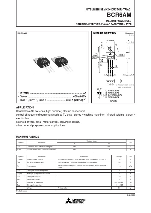
BCR6AM中文资料

360° 40 CONDUCTION RESISTIVE, 20 INDUCTIVE LOADS 0 0 1 2 3 4
5
6
7
8
9 10
RMS ON-STATE CURRENT (A)
RMS ON-STATE CURRENT (A)
Feb.1999
元器件交易网
MITSUBISHI SEMICONDUCTOR 〈TRIAC〉
元器件交易网
MITSUBISHI SEMICONDUCTOR 〈TRIAC〉
BCR6AM
MEDIUM POWER USE
NON-INSULATED TYPE, PLANAR PASSIVATION TYPE
BCR6AM
OUTLINE DRAWING
10.5 MAX
Dimensions in mm
CASE TEMPERATURE (°C)
20 18 16 360° 14 CONDUCTION 12 RESISTIVE, INDUCTIVE 10 LOADS 8 6 4 2 0 0 1 2 3 4 5 6 7 8 9 10
140 120 100 80 60
CURVES APPLY REGARDLESS OF CONDUCTION ANGLE
4.5
Ratings 6 60 15 5 0.5 10 2 –40 ~ +120 –40 ~ +125 2.0
Unit A A A2s W W V A °C °C g
V1. Gate open.
Feb.1999
元器件交易网
MITSUBISHI SEMICONDUCTOR 〈TRIAC〉
ON-STATE CURRENT (A)
GRM21BR61A106KE19L中文资料

物料编号:GRM21BR61A106KE19L细参数_易容网
MLCC即是多层陶瓷电容片式,是电子信息产品不可或缺的基本组件之一。
我国MLCC的生产起步在80年代初,行业早期主要是在外资企业的带动下发展起来的,近年来国内企业在技术上实现突破,行业国产化成效显著,并推动了MLCC产量迅速增长。
目前,MLCC的应用领域已从手机、电脑、电视机等消费电子领域,逐步拓展到新能源发电、新能源汽车、节能灯具、轨道交通、直流输变电、三网融合、高清电视、机顶盒、手机电视等多个行业。
对于这个悄悄活跃在人们生活中的元件你又知道多少呢.
本次易容网为大家推荐比较常用的MLCC村田 | Murata品牌的料号GRM21BR61A106KE19L的相关参数
易容网是深圳市易容信息技术有限公司独自研发的全球最大的MLCC搜索采购服务网站,2014年创立于深圳市南山区,全国首家电子元器件行业电容元件的搜索引擎及o2o商务服务平台。
易容网()现已建成全球最大的MLCC电容搜索引擎数据库,包含全球25家电容生产厂商超过28万组MLCC产品数据,用户可根据行业应用、物料编号、规格参数等信息快速的找到所有相关的MLCC电容数据。
易容网在搜索服务的前提下还提供村田、TDK、国巨、太阳诱电、风华高科等常见品牌产品的o2o商务服务,让企业客户实现询价、报价、在线订单、出库、实时物流、签收、账期服务等在线一站式商务服务体验。
配电电器 NWK1-GR 系列中英文液晶低压无功功率自动补偿控制器说明书

NWK1-GR 系列中英文液晶低压无功功率自动补偿控制器(新产品)NWK1-GR系列中文低压无功功率自动补偿控制器( 简称控制器 )采用手机菜单操作模式,实现人机交换,适用于电网的配电监测和共补、分补兼顾的无功补偿。
它采用ASIC处理芯片,通过FFT(快速傅立叶计算)对采集的三相电压和三相电流进行计算和分析,故在电网有较大的谐波分量下,能够正常以无功功率作为投切电容器的依据,并结合功率因数进行投切。
电容容量可按循环、编码或任意值组合,进行对单相或三相电容的匹配或投切,实现最优的补偿效果 ,它完全覆盖三相220V、380V、440V、690V等世界不同地区的低压电网系统,频率50Hz与60Hz通用,抗谐波能力更强,具有中英文版本,可定制光伏专用产品,是我公司推出的新一代智能型低压无功功率自动补偿控制器。
它内置集成了数字化的电网测量与记录储存功能于一身,采用大屏幕点阵液晶屏,中文或图形化实时显示几十种电量,并提供电能质量分析,谐波环境下电量测量精度高,具有谐波超值保护和RS485通讯传输功能。
符合标准:JB/T9663-2013;DL/T597-1996NWK 1 - G □- □ GB□信号控制方式:默认为继电器输出,D表示+12VDC补偿方式:GB 共补,FB 混补最大输出回路:12路、18路功能可选项:R表示RS485通讯+宽电压信号检测G表示功率因数,点阵液晶屏显示设计序号低压无功功率自动补偿控制器3.1 环境温度:-25℃~+40℃。
3.2 空气湿度:在40℃时不超过50%,20℃时不超过90%。
3.3 海拔高度:不超过2000米。
3.4 周围环境:无腐蚀性气体,无导电尘埃,无易燃易爆的介质存在。
3.5 安装地点无剧烈震动。
4.1 可实现全三相共补补偿,全单相分补补偿,三相与单相混合补偿。
四象限显示功率因数,以基波功率因数和基波无功功率为控制物理量,控制精度高,无投切震荡,并在有谐波的场合下能正确的显示电网功率因数和谐波含量。
MAX22506E MAX22506E 评估板概述说明书

Evaluates: MAX22506E MAX22506E Evaluation KitGeneral DescriptionThe MAX22506E evaluation kit (EV kit) is a fully assembledand tested PCB that demonstrates the functionality of theMAX22506E half-duplex, high speed RS-485/RS-422transceiver. The EV kit operates from a single 3V to 5.5Vsupply and includes selectable on-board termination.Features●Operates From a Single 3V to 5.5V Supply●Terminal Block Connectors for EasyRS-485/RS-422 Evaluation●Fully Assembled and Tested319-100683; Rev 0; 2/21Ordering Information appears at end of data sheet. Startup ProcedureThe EV kit is fully assembled and tested. Follow the steps below to verify board operation.1) Ensure that all jumpers are in their default positions(see Table 1).2) Set the DC power supply to 3.3V and connect theDC power supply between VCC (TP1) and GND(TP2) test points on the EV kit.3) Connect the oscilloscope probes to the DI input(TP7), A (TP8), B(TP9), and RO (TP4).4) Turn on the power supply.5) Set the signal/function generator to output a 25MHz0-to-3V square wave.6) Connect the signal/function generator to the DItest point.7) Using the oscilloscope, verify that the A, B, and RO-outputs switch as the DI signal toggles.Quick StartRequired Equipment●MAX22506E EV kit● 3.3V, 500mA DC power supply●50MHz Signal/function generator●OscilloscopeClick here to ask about the production status of specific part numbers.Detailed Description of HardwareThe MAX22506E EV kit is a fully assembled and tested circuit board for evaluating the MAX22506E high-speed, half-duplex RS-485/RS-422 transceiver (U1). The EV kit can be used for standalone evaluation or can be connected (using the on-board terminal block) to an RS-485/RS-422 network for easy in-system evaluation. Driver and Receiver Enable SelectionThe EV kit features three jumpers (J2, J4, and J5) to enable/disable the driver and receiver outputs. Set J2 to low (2-3) to enable the receiver. Set J4 to high (1-2) to enable the driver. To actively control both enables, remove the J2 and J4 shunts and close J5, which connects DE and RE together. J5 is DNI, by default. Install a 2-pin header to use the J5 jumper.Termination for an End-of-Line TransceiverThe MAX22506E EV kit includes a 120Ω termination resistor (R2) between the A and B RS-485 driver outputs/ receiver inputs on the MAX22506E.Table 1. Jumper Table (J2, J4, J5)JUMPER SHUNT POSITION DESCRIPTIONJ21-2RE is high. The RS-485 receiver is disabled. 2-3*RE is low. The RS-485 receiver is enabled.J41-2*DE is high. The RS-485 driver outputs are enabled. 2-3DE is low. The RS-485 driver outputs are disabled.J5Open*DE and RE are not connected together. Closed DE and RE are connected together.*Default position.Ordering InformationPART TYPE MAX22506EEVKIT#EV Kit #Denotes RoHS compliance.MAX22506E EV Kit Bill of MaterialsITEM REF_DESDNI/DNP QTYMFG PART #MANUFACTURERVALUEDESCRIPTION1C1-1GRM21BR61A106KE19;ECJ-2FB1A106;CL21A106KPCLQNC;GRM219R61A106KE44MURATA;PANASONIC;SAMSUNG ELECTRONICS;MURATA 10UFCAPACITOR; SMT (0805); CERAMIC CHIP; 10UF;10V; TOL=10%; MODEL=; TG=-55 DEGC TO +85 DEGC; TC=X5R2C2-1C0603C104K5RAC;C1608X7R1H104K;ECJ-1VB1H104K;GRM188R71H104KA93;CGJ3E2X7R1H104K080AA;C1608X7R1H104K080AA;CL10B104KB8NNN;CL10B104KB8NFN KEMET;TDK;PANASONIC;MURATA;TDK;TDK;SAMSUNG ELECTRO-MECHANICS; SAMSUNG ELECTRONICS 0.1UFCAPACITOR; SMT (0603); CERAMIC CHIP; 0.1UF;50V;TOL=10%; TG=-55 DEGC TO +125 DEGC; TC=X7R;3J2, J4-2PCC03SAAN SULLINSPCC03SAAN CONNECTOR; MALE; THROUGH HOLE; BREAKAWAY;STRAIGHT THROUGH; 3PINS; -65 DEGC TO +125 DEGC 4J7-1OSTTC042162ON-SHORE TECHNOLOGY INC OSTTC042162CONNECTOR; FEMALE; THROUGH HOLE; TERMINAL BLOCK ONE PIECE WIRE PROTECTOR; COLOR BLUE;RIGHT ANGLE; 4PINS5J8, J9-25-1634503-1TE CONNECTIVITY 5-1634503-1CONNECTOR; FEMALE; THROUGH HOLE;LOW PROFILE BNC PCB SOCKET; STRAIGHT; 5PINS 6R2-1CRCW0805120RFK VISHAY DALE 120RESISTOR; 0805; 120 OHM; 1%; 100PPM;0.125W; THICK FILM7R4-R6-3CRCW06030000ZS;MCR03EZPJ000;ERJ-3GEY0R00VISHAY DALE;ROHM;PANASONIC 0RESISTOR; 0603; 0 OHM; 0%; JUMPER;0.10W; THICK FILM8SPACER1-SPACER4-49032KEYSTONE 9032MACHINE FABRICATED; ROUND-THRU HOLE SPACER;NO THREAD; M3.5; 5/8IN; NYLON9TP1-15010KEYSTONE N/A TEST POINT; PIN DIA=0.125IN; TOTAL LENGTH=0.445IN;BOARD HOLE=0.063IN; RED; PHOSPHOR BRONZE WIRE SIL; 10TP2, TP3, TP10-35011KEYSTONEN/A TEST POINT; PIN DIA=0.125IN; TOTAL LENGTH=0.445IN;BOARD HOLE=0.063IN; BLACK; PHOSPHOR BRONZE WIRE SILVER PLATE FINISH;11TP4-TP9-65014KEYSTONE N/ATEST POINT; PIN DIA=0.125IN; TOTAL LENGTH=0.445IN;BOARD HOLE=0.063IN; YELLOW; PHOSPHOR BRONZE WIRE SILVER PLATE FINISH;12U1-1MAX22506EASA+MAXIMMAX22506EASA+EVKIT PART - IC; 50MBPS HALF-DUPLEX RS-485/RS-422TRANSCEIVERS WITH HIGH EFT IMMUNITY;PACKAGE OUTLINE DRAWING: 21-0041; PACKAGE CODE:S8+2C; PACKAGE LAND PATTERN: 90-009613PCB -1MAX22506EMAXIMPCB PCB:MAX22506E14C3, C4DNP 0C0402C103K5RAC;GRM155R71H103KA88;C1005X7R1H103K050BE;CL05B103KB5NNN;UMK105B7103KV KEMET;MURATA;TDK;SAMSUNG ELECTRONIC;TAIYO YUDEN0.01UF CAPACITOR; SMT (0402); CERAMIC CHIP; 0.01UF; 50V;TOL=10%; TG=-55 DEGC TO +125 DEGC; TC=X7R15J1DNP 0PBC06SAAN SULLINS ELECTRONICS CORP.PBC06SAANCONNECTOR; MALE; THROUGH HOLE; BREAKAWAY;STRAIGHT; 6PINS; -65 DEGC TO +125 DEGC 16J3, J6, J10, J11DNP 0131-5031-00TEKTRONIX 131-5031-00CONNECTOR; WIREMOUNT; 3 GHZ 20X LOWCAPACITANCE PROBE; STRAIGHT; 5PINS17J5DNP 0PCC02SAANSULLINSPCC02SAANCONNECTOR; MALE; THROUGH HOLE; BREAKAWAY;STRAIGHT THROUGH; 2PINS; -65 DEGC TO +125 DEGC 18R1, R3DNP 0CRCW0402100RFK; 9C04021A1000FL;RC0402FR-07100RLVISHAY DALE;PANASONIC;YAGEO PHYCOMP100RESISTOR; 0402; 100 OHM; 1%; 100PPM; 0.063W;THICK FILM19R7, R8DNP0CRCW06031K00FK;ERJ-3EKF1001VISHAY DALE;PANASONIC1K RESISTOR; 0603; 1K; 1%; 100PPM; 0.10W; THICK FILMTOTAL27MAX22506E EV Kit—Top SilkscreenMAX22506E EV Kit—TopMAX22506E EV Kit—BottomMAX22506E EV Kit—Bottom SilkscreenMaxim Integrated cannot assume responsibility for use of any circuitry other than circuitry entirely embodied in a Maxim Integrated product. No circuit patent licenses are implied. Maxim Integrated reserves the right to change the circuitry and specifications without notice at any time.Revision HistoryREVISION NUMBERREVISION DATEDESCRIPTIONPAGES CHANGED2/21Initial release—For pricing, delivery, and ordering information, please visit Maxim Integrated’s online storefront at https:///en/storefront/storefront.html.。
LDO电路设计规范

本规范主要起草人:王振华。
LDO电路设计规范
11
本规范规定了LDO电路输入输出电容的选择以及电源输出的电流的基本要求。
12
下列文件中的条款通过本标准的引用而成为本标准的条款。凡是注日期的引用文件,其随后所有的修改单(不包括勘误的内容)或修订版均不适用于本标准,然而,鼓励根据本标准达成协议的各方研究是否可使用这些文件的最新版本。凡是不注日期的引用文件,其最新版本适用于本标准。
C2
钽电容
47Uf16V
800mΩ
TAJD476K016RNJ
输入电压VIN
输出电压VOUT
最大允许输出电流
5V
3.3V
200mA
4.2MIC37302-WU典型电路设计
电容的选取
电容类型
容值/耐压
等效串联电阻
型号
C1
瓷片电容
10Uf10V
10 mΩ
GRM21BR61A106KE19L
C2
瓷片电容
47Uf10V
1
低压降(LDO)线性稳压器的成本低,纹波小,静态电流小,这些是它的突出优点。它需要的外接元件也很少,通常只需要一个输入电容和输出电容。但是他也有很明显的缺点,发热量大、效率低。设计注意事项主要有输入电容、输出电容的选择以及本身的功耗。
在电路设计中,硬件工程师选用了多款LDO电源芯片,每一种LDO电源芯片对输入输出电容都有不同的要求,一颗LDO芯片也可以使用多种电容以保证电源电压输出的稳定。这些造成了不同的硬件工程师在使用同一颗LDO芯片设计了不同的电路。本规范主要对LDO的输入输出电容的选择以及输出电流进行规范,方便电源的设计以及测试。
电容特性

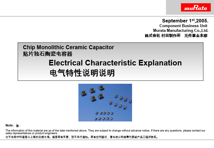
Chip Monolithic Ceramic Capacitor 贴片独石陶瓷电容器 Electrical Characteristic Explanation电气特性说明说明September 1st ,2005.Component Business Unit Murata Manufacturing Co.,Ltd.株式会社村田制作所 元件事业本部Note : 注:The information of this material are as of the date mentioned above. They are subject to change without advance notice. If there are any questions, please contact our sales representatives or product engineers.1.Material of Capacitor 电容器的材料2.Ceramic material (Class 1, Class 2) 陶瓷材料3.Electrical Characteristic (Class 1, Class 2) 陶瓷电容器的电气特性4. Function of Ceramic Capacitor 陶瓷电容器的功能5.Rated Voltage Explanation (Ceramic Capacitor) 额定电圧说明(陶瓷电容器)Contents内容Fixed Capacitor 固定电容器Film 薄膜Ceramic 陶瓷Aluminum 铝Glass 玻璃Mica 云母ElectrolyticDouble Layer双倍电解层Using plastic film as the dielectric , thin metal film metal as inner electrodes ,stacked and rolled up together.Non polarized organic film capacitor.Using Ceramic as the dielectric , metal baked with ceramic as innerelectrodes , non-polarized and non-organic capacitors.Using high purity conductive material as positive electrodes , oxidizedlayers on the electrodes , either liquid or solid electrolyte contactingoxidized layers as the negative electrodes.Using glass film or glass powder as the dielectric , metallic foil ormetallic paste as electrodes.Using natural Mica as the dielectric , metallic foil as inner electrodes.Impregnated collecting electrode with liquid electrolyte , dividedinto positive / negative / by a porous separator as polarized capacitors.Material of Capacitor 电容器的材料100fF 1pF 10pF 100pF 1nF 10nF 100nF 1µF 10µF 100µF 1mF 10mFAluminum Electrolytic Capacitor铝电解电容器Glass Capacitor 玻璃电容器Mica Capacitor 云母电容器Semi-conductive Capacitor 半导体电容器Monolithic Ceramic Capacitor 贴片陶瓷电容器Disc Ceramic Capacitor (Disk-type) 陶瓷电容器(圆盘状)Film Capacitor 薄膜电容器Tantalum Electrolytic Capacitor钽电解电容器Capacitance Range by Material电容器的材料Fixed Capacitor 固定的电容器Film 薄膜Ceramic 陶瓷Aluminum 铝Glass 玻璃Mica 云母ElectrolyticDouble Layer 双倍电解层Polyester Capacitor (Mylar)聚酯电容器Polypropylene 聚丙烯Polycarbonate 聚碳酸酯Polyethylene 聚乙烯Relatively small.Higher resistance , better TC Large / ExpensiveHigher resistance , better TC Higher BDV , LargeVariety of TCs , suitable for Temp. compensating Higher C/V per unit volume.Or Higher ‘k’.Small size for disc cap , lower BDVLarge cap , small size Polarized / Low BDV Large cap. Polarity Higher BDV , Better TC Low cap. Expensive Higher BDV , Better TC Low cap. ExpensiveExtremely large cap. Backup for batteryClass 1 系列1Class 2 系列2Class 3系列3TANTAL ALMaterial of Capacitor电容器的材料Ceramic Material & Characteristic陶瓷材料和特性[ Classification by Temperature Characteristic ]Class 1 : C0G, U2J Class 2 : X7R, X5R, Y5VClass Ceramic Material Ceramic CharacterTemp. Char.Capacitance Range Recommended Circuit 分类陶瓷材料陶瓷特性温度特性容量範囲推荐电路Class 1Temperature Capacitance A ccuracy <EIA >CHIP0.1pF - 0.1uF In Band Pass Filter Circuit 分类1Compensation for temperature C0G,U2J 片状独石(0R1 - 104)带通滤波电路温度補償用対温度容量値精度大<EIA-J>In Coupling Circuit(TC 系)CH,UJ,SLLEAD 1pF - 680nF 耦合电路挿脚(010 - 683)In Temp. Compensasion Circuit 温度補償电路Class2High Dielectric Hi Capacitance Value <EIA >CHIP100pF - 100uF In By-Pass Circuit分类2高介电系列大容量X7R,Y5V,片状独石(101 - 107)旁路电路(Hi-K 系)X5R,X6S In Decoupling Circuit<EIA-J>LEAD 220pF - 4.7uF 去耦电路B, R, F挿脚(221 - 475)In Resonance Circuit 振荡电路Temp. Characteristic (Class 1 & Class 2)温度特性(例)-100-80-60-40-2002040-75-50-25255075100125150TEMPERATURE (deg. C)C A P . C H A N G E (%)C0G (Class1)U2J (Class1)X7R (Class2)X5R (Class2)Y5V (Class2)[ Temp. Char. Specification ]C0G : 0±60 ppm/℃(-55 ~+ 125℃)U2J : 750±120 ppm/℃(-55 ~+ 85℃)X7R : ±15 % (-55 ~+ 125℃)X5R : ±15 % (-55 ~+ 85℃)Y5V : + 22, -82 % (-55 ~+ 85℃)-100-80-60-40-2002040-60-40-2020406080100120140Temperature (deg)C a p a c i t a n c e C h a n g e r a t e (%)MLCC 陶瓷0805 X5R 10uF 6.3V(Class 2)MLCC 陶瓷1206 Y5V 10uF 6.3V(Class 2)Ta 钽10uF 16VAL 铝10uF 16VTemp. Characteristic (AL/TAN-CAP Comparison)温度特性(例)MLCC 陶瓷0402 C0G 1000pF 50V(Class 1)Bias Characteristic (Class 1 & Class 2)电圧特性(例)-100-80-60-40-20201020304050DC VOLTAGE (VDC)C A P . C H A N G E (%)C0G/50V (Class1)U2J/50V (Class1)X7R/50V (Class2)Y5V/50V (Class2)Y5V/50VC0G/50VU2J/50VX7R/50VBias Characteristic (AL/TAN-CAP Comparison)电圧特性(例)-100-75-50-2525-11357911131517Voltage (V.DC)C a p a c i t a n c e c h a n g e r a t e (%)MLCC 0805 X5R 10uF 6.3V(Class 2)MLCC 1206 Y5V 10uF 6.3V(Class 2)Ta 10uF 16VAL 10uF 16VMLCC 陶瓷0402 C0G 1000pF 50V(Class 1)Freq. Characteristic (Class 1 & Class 2)频率特性(例)0.0010.010.111010010000.1110100100010000FREQUENCY [MHz]I M P E D A N C E /E S R [o h m ]X7R/1000pF X7R/10000pF X7R/0.1uF C0G/1000pF C0G/10000pF C0G/0.1uFX7R/1000pFX7R/0.1uFX7R/10000pFC0G/1000pFC0G/0.1uFC0G/10000pFFRS : Class 1FRS : Class 2Freq. Characteristic (Capacitance Value)频率特性(例)0.00010.0010.010.11101000.00010.0010.010.1110100100010000FREQUENCY [MHz]I M P E D A N C E /E S R [o h m ]X7R/1000pF X7R/10000pF X7R/0.1uF X5R/1uF X5R/10uF X5R/100uFX7R/1000pFX7R/0.1uFX7R/10000pF X5R/1uF X5R/10uFX5R/100uF0.0010.010.11101001000100100010000100000100000010000000Frequency (Hz)I m p e d a n c e (o h m )MLCC 0805 X5R 10uF 6.3VMLCC 1206 Y5V 10uF 6.3VTa 10uF 16VAL 10uF 16VFreq. Characteristic (AL/TAN-CAP Comparison)频率特性(例)Freq. Characteristic Explanation频率特性说明Z = R 2+ (ωL -1/ωC)2 (微量) (微量)= R 2+(2πfL -1/2πfC)2(频率f→大) (2πfL →大) (1/2πfL →少)(容量C→大) (1/2πfL→少)Equivalent capacitor circuit相等的电容电流Capacitance 容量ESL等系列电感ESR等系列电阻ABSTRACT 摘要-Every capacitor has ESR(equivalent series resistance) and ESL.每个电容器都有ESR (等系列电阻)和ESL( 等系列电感)。
补偿仪控制器说明书

一.PZHG 滤波组件
1.型号说明
2.组成 XZ 系列 滤波电抗器 LHPZ 系列 滤波电容器 注:电抗器和电抗器的说明见本说明书第五部分 3.安装接线图
4.滤波组件使用说明 ● 参数
1
―适用环境温度类别:-25/B ―电网电压:系统电压±10%
―谐波环境:Uh 3 =0.5%,Uh 5 = Uh 7 =5.0%(轻载环境 I h 5 =40%,I h 7 =20%)
三.滤波模块整机安装示意图....................................................................................................... 6
四.电容器和电抗器使用说明....................................................................................................... 6 1.电容器....................................................................................................................................6 1.1 型号说明.....................................................................................................................6 1.2 外形说明.....................................................................................................................7 1.3 技术指标.....................................................................................................................7 2.电抗器....................................................................................................................................8 2.1 型号说明.....................................................................................................................8 2.2 外形说明.....................................................................................................................8 2.3 外形尺寸.....................................................................................................................8
MURATA 全系列产品

CDBLB455KCAY28-B0
CES302G01BCB000RB2
CES321G95ECB000RB3
CES40881MDCB000RB2
CFUKG455KE4A-R0
CFULB455KG1A-B0
CFWKA455KFFA-R0
GRM1885C1HR50BZ01D GRM1885C2A200JA01D GRM1887U1H181JZ01D
GRM188B11C104KA01D GRM188B11E222KA01D GRM188B11E473KA01D
GRM188B11H102KA01D GRM188B11H103KA01D GRM188B11H152KA01D
GRM1555C1H271JA01D GRM1555C1H2R0BZ01D GRM1555C1H2R0CZ01D
GRM1555C1H2R2CZ01D GRM1555C1H2R7CZ01D GRM1555C1H300JZ01D
GRM1555C1H301JA01D GRM1555C1H330JZ01D GRM1555C1H331JA01D
GRM0335C1E120JD01D GRM0335C1E180JD01D GRM0335C1E1R8CD01D
GRM0335C1E220JD01D GRM0335C1E330JD01D GRM0335C1E390JD01D
GRM0335C1E470JD01D GRM0335C1E8R0DD01D GRM0335C1H101JD01D
GRM155R71C223KA01D GRM155R71C393KA01D GRM155R71C473KA01D
GRM155R71C823KA88D GRM155R71E103KA01D GRM155R71E183KA61D
SMT物料最小包装

1206 SOD-123
30 2980101000476 31 2980101000488 32 2980101000487
GRM1555C1H102JA01D RTT02393JTH RTT02682JTH
0402 0402 0402
33 2980101000293 MPIH252012-1R5M-LF-Z SMD25_20
0402 0402 0402
6 2980101000502 7 2980101000468 8 2980101000343
CL05A475MP5NRNC RTT02102JTH RTT02473JTH
0402 0402 0402
9 2980101000334 GRM155R61A105K 10 3180280200019 ES0603V014CT
10000 10000 10000
功率电感 MPIH252012-1R5M-LF-Z 2.5*2.0*1.2 1.5uH ±20% CH 0402封装贴片电容 4.7pF ±0.5pF 50V MURATA GRM1555C1H4R7CA01D CH 0402封装贴片电阻 100K ±1% RTT02104FTH CH 0402封装贴片电阻 130K ±1% RTT02134FTH CH 0402封装贴片电阻 240R ±1% RTT02241FTH CH 0402封装贴片电阻 30K ±5% RTT02303JTH CH 1206封装贴片电容 22uF ±10% 16V MURATA GRM31CR61C226KE15L CH 0402封装贴片电容 10nF ±10% 50V MURATA GRM155R71H103KA88D CH 0402封装贴片电容 10pF ±5% 50V MURATA GRM1555C1H100JA01D CH 0402封装贴片电容 2.2pF ±0.25pF 50V SAMSUNG CL05C2R2CB5NNNC CH 0402封装贴片电容 2.2uF ±10% 16V MURATA GRM155R61C225KE44D CH 0402封装贴片电容 4.7nF ±10% 50V SAMSUNG CL05B472KB5NNNC CH 0402封装贴片电容 8pF ±5% 50V MURATA GRM1555C1H8R0C CH 0402封装贴片电阻 150K ±1% RTT021503FTH CH 0402封装贴片电阻 2K2 ±5% RTT02222JTH CH 0603封装贴片电容 330nF ±10% 16V MURATA GRM188R71C334KA01D CH AO3401A 贴片MOS管 P SOT-23 CH 功率电感 MPIT4018-2R2M-LF 4.0*4.0*1.8 2.2uH ±20% CH 功率电感 SWPA8040S220MT SMD8*8*4mm 22uH ± 20% CH 集成电路-TJA1042/3/1 SO-8 晶振 AH03270001 32.768KHz SMD3215 贴片电感 JSRF3225-601P 3.2*2.5 600R CH 贴片电解电容 VZH221M1ATR-0806 220uF 10V 0806 ±20% CH 贴片电解电容VZH221M1ETR0810 220uF 25V 0810 ±20% 0805封装贴片电阻 0R ±5% RTT05000JTH 1206封装贴片电阻 10R ±5% RTT06100JTH CH
村田电容大全

村田排容:在一个介质体内由多个电容元件组合而成的独石电容器,特点:小型且大电容量与单个电容元件相比可获得更大的静电电容量,可实现高密度贴装,从而能缩小贴装面积和节约贴装成本
GNM314R71E104MA11D
GNM314R71C104MA01L
GNM2145C1H221KD01D
LLL317R71H473MA01L
LLL215R71A154MA11L
LLL185R71C473MA01L
LLL317R71H223MA01L
LLL315R71E473MA11L
LLL216R71H223MA01L
LLL31MR70J475MA01L
LLL315R71C224MA11L
GJM0336C1E180JB01D
GJM1555C1HR20BB01D
GJM1555C1H9R8WB01D
GJM1555C1H6R1BB01D
GJM1555C1H110GB01D
GJM0335C1ER50BB01D
GJM1555C1H1R6WB01D
GJM1555C1HR80WB01D
MA292R0CAN
MA29100JAN
MA29150JAN
MA297R5CAN
MA29820JAN
MA298R2CAN
MA29270JAN
MA29220JAN
MA291R5CAN
MA291R0CAN
MA29560JAN
MA29102JAN
MA19330JAN
村田低ESR电容器:ESR是Equivalent Series Resistance的缩写,即“等效串联电阻”。理想的电容自身不会有任何能量损失,但实际上,因为制造电容的材料有电阻,电容的绝缘介质有损耗。这个损耗在外部,表现为就像一个电阻跟电容串联在一起,所以就称为“等效串联电阻”。有的电容还会标出ESR值(等效串联电阻),ESR越低,损耗越小,输出电流就越大,电容器的品质越高
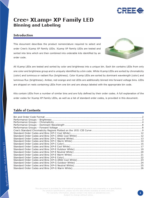
最全美国Cree公司大功率LED全套芯片产品规格说明书

This document is provided for informational purposes only and is not a warranty or a specification. For product specifications, please see the data sheets available at . For warranty information, please contact Cree Sales at sales@. Copyright © 2008-2010 Cree, Inc. All rights reserved. The information in this document is subject to change without notice. Cree, the Cree logo and XLamp arenc.
Cree® XLamp® XP Family LED
Binning and Labeling
Introduction
This document describes the product nomenclature required to select and order Cree’s XLamp XP Family LEDs. XLamp XP Family LEDs are tested and sorted into bins which are then combined into orderable kits identified by an order code.
Table of Contents
Bin and Order-Code Format....................................................................................................................... 2 Performance Groups – Brightness............................................................................................................... 3 Performance Groups – Chromaticity............................................................................................................ 4 Performance Groups – Dominant Wavelength............................................................................................... 8 Performance Groups – Forward Voltage....................................................................................................... 8 Cree’s Standard Chromaticity Regions Plotted on the 1931 CIE Curve.............................................................. 9 Standard Order Codes and Bins (XP-C Cool White). ..................................................................................... 12 Standard Order Codes and Bins (XP-C ANSI Cool White). ............................................................................. 12 Standard Order Codes and Bins (XP-C Neutral White). ................................................................................. 13 Standard Order Codes and Bins (XP-C Warm White). ................................................................................... 14 Standard Order Codes and Bins (XP-C Color). ............................................................................................. 15 Standard Order Codes and Bins (XP-E Cool White)...................................................................................... 17 Standard Order Codes and Bins (XP-E Outdoor White). ................................................................................ 19 Standard Order Codes and Bins (XP-E Neutral White).................................................................................. 20 Standard Order Codes and Bins (XP-E Warm White).................................................................................... 21 Standard Order Codes and Bins (XP-E Color). ............................................................................................. 22 Standard Order Codes and Bins (XP-G ANSI Cool White). ............................................................................. 23 Standard Order Codes and Bins (XP-G Outdoor White)................................................................................ 24 Standard Order Codes and Bins (XP-G Neutral White). ................................................................................. 25 Standard Order Codes and Bins (XP-G Warm White). ................................................................................... 26
村田芯片型号

村田芯片型号村田制作的多层陶瓷电容器芯片(Multi-Layer Ceramic Capacitors, MLCCs)是电子产品中常见的一种被广泛应用的元件。
这些电容器芯片以其小巧的尺寸、高性能和可靠性而备受推崇。
在此,我们将介绍一些村田芯片型号及其应用。
1. 村田芯片型号 GRM21BR61A106KE19L:这款芯片是一种陶瓷电容器,具有1uF的电容值。
它广泛应用于通信设备、计算机、数码产品和汽车电子等领域。
该型号的特点是体积小、频率响应快且具有低温漂移。
2. 村田芯片型号 GRM188R71H104KA93D:这是一种10uF的陶瓷电容器,适用于各种电子设备。
它具有低ESR(等效串联电阻)和低漏电流的特点,能够提供可靠的电源稳定性和滤波效果。
因此,在电源和信号处理电路中广泛应用。
3. 村田芯片型号 GRM155R60J475ME87D:这款芯片是一种4.7uF的陶瓷电容器,特别适用于移动通信设备、计算机和消费类电子产品。
它具有高电容密度和低ESR的特点,能够提供稳定的电源和滤波效果,使设备具有较好的性能和可靠性。
4. 村田芯片型号 GRM32ER71H475KA88L:这是一种4.7uF的陶瓷电容器,广泛应用于高频电路和功率管理电路。
它具有低ESR和低ESL(等效串联电感)的特点,适用于对电源稳定性和信号传输质量要求较高的应用。
5. 村田芯片型号 GRM188R61C106MAALD:这款芯片是一种10uF的陶瓷电容器,适用于各种电子设备。
它具有高电容密度和低ESR的特点,能够提供稳定的电源和滤波效果。
该型号还具有可靠性高、耐高温性能好的特点,适用于工业和汽车电子等领域。
6. 村田芯片型号 GRM155R61A475MEAAJ:这是一种4.7uF的陶瓷电容器,适用于移动通信设备、计算机和消费类电子产品。
它具有高电容密度和低ESR的特点,能够提供稳定的电源和滤波效果,同时也具有低压降和快速充电的特点,满足设备对电源质量和响应速度的要求。
村田陶瓷电容命名规则

村田陶瓷电容命名规则(原创版)目录I.村田陶瓷电容的概述II.村田陶瓷电容的命名规则A.型号的构成B.各部分代表的含义III.举例说明A.GRM188R71H103KA01D 型号的解析B.GRM21BR61A106KE19L 型号的解析IV.村田电容的命名规则与电感、电阻的命名规则的区别正文I.村田陶瓷电容的概述村田陶瓷电容是村田公司生产的一种多层陶瓷片式电容,具有体积小、容量大、稳定性高、耐压能力强等优点,广泛应用于各种电子设备中。
II.村田陶瓷电容的命名规则村田陶瓷电容的型号由多个部分组成,每个部分都有特定的含义。
以下是村田陶瓷电容型号的命名规则:A.型号的构成村田陶瓷电容的型号通常由 10 个部分组成,例如:GRM188R71H103KA01D。
B.各部分代表的含义1.GR:型号2.M:尺寸3.18:温度系数4.8:电压5.R7:厚度6.1H:人别规格代号7.103:精度8.K:电容类型9.A01:批包装10.D:电容的其它特性III.举例说明A.GRM188R71H103KA01D 型号的解析- GR:型号为 GRM188R71H103KA01D - M:尺寸为 0805(2.01.2mm 长和宽)- 18:温度系数为 x7r1a- 8:电压为 10v- R7:厚度为 0.15mm- 1H:人别规格代号为 H- 103:精度为 -10%- K:电容类型为 C- A01:批包装为 A01- D:电容的其它特性为无B.GRM21BR61A106KE19L 型号的解析- GR:型号为 GRM21BR61A106KE19L- M:尺寸为 0603(2.01.2mm 长和宽)- 21:温度系数为 x7r1a- BR:厚度为 0.15mm- 61:电压为 10v- A:精度为 -10%- 106:电容类型为 C- K:人别规格代号为 E19- E19:批包装为 E19- L:电容的其它特性为无IV.村田电容的命名规则与电感、电阻的命名规则的区别村田电容的命名规则主要由型号、尺寸、温度系数、电压、厚度、精度、电容类型、人别规格代号、批包装和电容的其它特性组成。
BLM21AG601SN1中文资料

Part Number
BLM03AG100SN1 BLM03AG700SN1 BLM03AG121SN1 BLM03AG241SN1 BLM15AG100SN1 BLM15AG700SN1 BLM15AG121SN1 BLM15AG221SN1 BLM15AG601SN1 BLM15AG102SN1 BLM15AG601AN1 BLM15AG102AN1 BLM15BB050SN1 BLM15BB100SN1 BLM15BB220SN1 BLM15BB470SN1 BLM15BB750SN1 BLM15BB121SN1 BLM15BB221SN1 BLM15BD750SN1 BLM15BD121SN1 BLM15BD221SN1 BLM15BD471SN1 BLM15BD601SN1 BLM15BD102SN1 BLM15BD182SN1 BLM15PG100SN1 BLM15HG601SN1 BLM15HG102SN1 BLM15HD601SN1 BLM15HD102SN1 BLM15HD182SN1 BLM15EG121SN1 BLM15EG221SN1 BLM18AG121SN1 BLM18AG151SN1 BLM18AG221SN1 BLM18AG331SN1 BLM18AG471SN1 BLM18AG601SN1 BLM18AG102SN1 BLM18BA050SN1 BLM18BB050SN1 BLM18BA100SN1 BLM18BB100SN1 BLM18BA220SN1 BLM18BB220SN1 BLM18BA470SN1 BLM18BB470SN1 BLM18BB600SN1 BLM18BA750SN1 BLM18BB750SN1 BLM18BA121SN1 BLM18BB121SN1 BLM18BD121SN1 BLM18BB141SN1
- 1、下载文档前请自行甄别文档内容的完整性,平台不提供额外的编辑、内容补充、找答案等附加服务。
- 2、"仅部分预览"的文档,不可在线预览部分如存在完整性等问题,可反馈申请退款(可完整预览的文档不适用该条件!)。
- 3、如文档侵犯您的权益,请联系客服反馈,我们会尽快为您处理(人工客服工作时间:9:00-18:30)。
物料编号:GRM21BR61A106KE19L的详细参数_易容网
MLCC即是多层陶瓷电容片式,是电子信息产品不可或缺的基本组件之一。
我国MLCC的生产起步在80年代初,行业早期主要是在外资企业的带动下发展起来的,近年来国内企业在技术上实现突破,行业国产化成效显著,并推动了MLCC产量迅速增长。
目前,MLCC的应用领域已从手机、电脑、电视机等消费电子领域,逐步拓展到新能源发电、新能源汽车、节能灯具、轨道交通、直流输变电、三网融合、高清电视、机顶盒、手机电视等多个行业。
对于这个悄悄活跃在人们生活中的元件你又知道多少呢.
本次易容网为大家推荐比较常用的MLCC村田 | Murata品牌的料号GRM21BR61A106KE19L的相关参数
易容网是深圳市易容信息技术有限公司独自研发的全球最大的MLCC搜索采购服务网站,2014年创立于深圳市南山区,全国首家电子元器件行业电容元件的搜索引擎及o2o商务服务平台。
易容网()现已建成全球最大的MLCC电容搜索引擎数据库,包含全球25家电容生产厂商超过28万组MLCC产品数据,用户可根据行业应用、物料编号、规格参数等信息快速的找到所有相关的MLCC电容数据。
易容网在搜索服务的前提下还提供村田、TDK、国巨、太阳诱电、风华高科等常见品牌产品的o2o商务服务,让企业客户实现询价、报价、在线订单、出库、实时物流、签收、账期服务等在线一站式商务服务体验。
