ELM-2081EGWA中文资料
耐低温不干胶

耐低温不干胶材料为东莞俊泰不干胶有限公司研发、生产的,广泛应用于铜版纸不干胶制作、书写纸不干胶制作的不干胶材料,适用于冷冻食品等。
随着人们生活条件的不断变好,人们对于食品方面的要求也在不断提高,如最近海淘食品的流行就是这方面的一个体现。
食品的存储和温度密切相关,其中有一部分食品,例如冷冻肉制品、粽子、火锅、饺子包子、海鲜、食料、冰淇淋,长期存储需要冷冻环境,甚至有的低温要到达零下18度以下。
冷冻食品在运输存储过程中同样需要冷冻的环境,因此部分物流标签需要满足适应冷冻环境的贴标要求。
物流标签主要是用于外包装的纸箱或者塑料箱上。
因此就需要有专门的耐低温不干胶材料,能适应零下18度以下的温度。
由于温度、食品包装的不规则、物流纸箱表面的粗糙度等因素,物流标签贴标过程中会出现这样或那样的问题:1. 在冷冻食品的表面大多不可避免有冰霜或者水分,并且因为温度很低因此耐低温不干胶的胶水必须有很强的低温初粘力。
2. 冷链物流的纸箱表面粗糙需要耐低温不干胶的胶水有比较好的低温流动性。
3. 而且很多冷冻食品外包装的形状不规则,会造成胶面和被贴物的接触面积减少,所以胶水的低温流动性必须要好。
否则容易发生边缘起翘和掉标危险。
我公司的耐低温不干胶材料基本技术参数。
销售代码:55018(耐低温可移除不干胶)中文名称:优质铜版纸/可移除性胶水/白色格拉辛底65面材:优质铜版纸多用途标签纸,特别应用于需要精细印刷高质量多色标签。
克重:80 g/m2 ISO 536厚度:72 μm ISO 534抗张强度:(MD) 3.7 KN/m ISO 1924/2抗张强度:(CD) 1.03 KN/m ISO 1924/2白度:88 % ISO 2470/1粗糙度:0.8 μm ISO 8791不透明度:89 % ISO 2471光泽度:70 % HUNTER 75°挺度:(MD)0.2 mNm ISO/DP 2493挺度:(CD)0.1 mNm ISO/DP 2493胶粘剂:可移除性胶可移除性胶,在光滑的表面具有长期的可移除功能。
贴片元件E
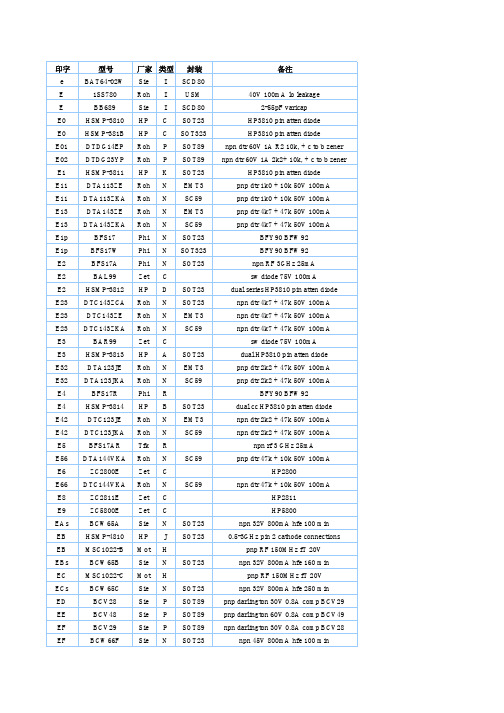
印字型号厂家类型封装备注e BAT64-02W Sie I SCD80E 1SS780 Roh I USM 40V 100mA lo leakageSCD80 2-55pFvaricapIE BB689 SieE0 HSMP-3810 HP C SOT23 HP3810 pin atten diodeE0 HSMP-381B HP C SOT323 HP3810 pin atten diodeE01 DTDG14EP Roh P SOT89 npn dtr 60V 1A R2 10k, + c to b zener E02 DTDG23YP Roh P SOT89 npn dtr 60V 1A 2k2+ 10k, + c to b zener E1 HSMP-3811 HP K SOT23 HP3810 pin atten diodeE11 DTA113ZE Roh N EMT3 pnp dtr 1k0 + 10k 50V 100mAE11 DTA113ZKA Roh N SC59 pnp dtr 1k0 + 10k 50V 100mAE13 DTA143ZE Roh N EMT3 pnp dtr 4k7 + 47k 50V 100mAE13 DTA143ZKA Roh N SC59 pnp dtr 4k7 + 47k 50V 100mABFW92SOT23 BFY90E1p BFS17 PhiNSOT323 BFY90BFW92NE1p BFS17W PhiE2 BFS17A Phi N SOT23 npn RF 3GHz 25mAE2 BAL99 Zet C sw diode 75V 100mAE2 HSMP-3812 HP D SOT23 dual series HP3810 pin atten diodeE23 DTC143ZCA Roh N SOT23 npn dtr 4k7 + 47k 50V 100mAE23 DTC143ZE Roh N EMT3 npn dtr 4k7 + 47k 50V 100mAE23 DTC143ZKA Roh N SC59 npn dtr 4k7 + 47k 50V 100mAE3 BAR99 Zet C sw diode 75V 100mAE3 HSMP-3813 HP A SOT23 dual HP3810 pin atten diodeE32 DTA123JE Roh N EMT3 pnp dtr 2k2 + 47k 50V 100mAE32 DTA123JKA Roh N SC59 pnp dtr 2k2 + 47k 50V 100mAR BFY90BFW92E4 BFS17R PhiE4 HSMP-3814 HP B SOT23 dual cc HP3810 pin atten diodeE42 DTC123JE Roh N EMT3 npn dtr 2k2 + 47k 50V 100mAE42 DTC123JKA Roh N SC59 npn dtr 2k2 + 47k 50V 100mAE5 BFS17AR Tfk R npn rf 3 GHz 25mAE56 DTA144VKA Roh N SC59 pnp dtr 47k + 10k 50V 100mAC HP2800E6 ZC2800E ZetE66 DTC144VKA Roh N SC59 npn dtr 47k + 10k 50V 100mAE8 ZC2811E ZetC HP2811C HP5800E9 ZC5800E ZetEAs BCW65A Sie N SOT23 npn 32V 800mA hfe 100 minEB HSMP-4810 HP J SOT23 0.5-3GHz pin 2 cathode connections EB MSC1022-B Mot H pnp RF 150MHz fT 20VEBs BCW65B Sie N SOT23 npn 32V 800mA hfe 160 minEC MSC1022-C Mot H pnp RF 150MHz fT 20VECs BCW65C Sie N SOT23 npn 32V 800mA hfe 250 minED BCV28 Sie P SOT89 pnp darlington 30V 0.8A comp BCV29 EE BCV48 Sie P SOT89 pnp darlington 60V 0.8A comp BCV49 EF BCV29 Sie P SOT89 npn darlington 30V 0.8A comp BCV28 EF BCW66F Sie N SOT23 npn 45V 800mA hfe 100 minEG BCV49 Sie P SOT89 npn darlington 60V 0.8A comp BCV48 EGs BCW66G Sie N SOT23 npn 45V 800mA hfe 160 minEHAA MAX6326_R22-T Max ZB SOT23 microproc -ve reset gen 2.200VEHs BCW66H Sie N SOT23 npn 45V 800mA hfe 240 minEIAA MAX6327_R22-T Max ZB SOT23 microproc +ve reset gen 2.200VEJAA MAX6328_R22-T Max ZB SOT23 microproc -ve reset gen 2.200VEKs BCX41 Sie N SOT23 gp npn 125V 1A comp BCX42 ET BCW65AR Sie R SOT23R npn 32V 800mA hfe 100 min EU BCW65BR Sie R SOT23R npn 32V 800mA hfe 160 min EW BCW65CR Sie R SOT23R npn 32V 800mA hfe 240 minEWAA MAX6326_R23-T Max ZB SOT23 microproc -ve reset gen 2.320VEX BCW65FR Sie R SOT23R npn 45V 800mA hfe 100 minEXAA MAX6326_R24-T Max ZB SOT23 microproc -ve reset gen 2.400VEY BCW65GR Sie R SOT23R npn 45V 800mA hfe 160 minEYAA MAX6326_R25-T Max ZB SOT23 microproc -ve reset gen 2.500VEZ BCW65HR Sie R SOT23R npn 45V 800mA hfe 240 minEZAA MAX6326_R26-T Max ZB SOT23 microproc -ve reset gen 2.630V。
Moxa EDS-208系列产品说明书

P/N: 1802002080016*1802002080016*EDS-208 Series Quick Installation GuideMoxa EtherDevice SwitchVersion 5.2, January 2021Technical Support Contact Information/support2021 Moxa Inc. All rights reserved.OverviewThe EDS-208 series of Moxa EtherDevice™ Switches are entry-level8-port Ethernet Switches that provide a cost-effective solution for industrial Ethernet connections. EDS-208 provides a choice of 12 to 48 VDC power input. The switches can operate reliably in a temperature range of -10 to 60°C, and the rugged hardware design makes EDS-208 perfect for ensuring that your Ethernet equipment can be used in demanding industrial environments.Package ChecklistMoxa EDS-208 is shipped with the following items. If any of these items is missing or damaged, please contact your customer service representative for assistance.• 1 EDS-208 or EDS-208-M-SC or EDS-208-M-ST•Quick installation guide (printed)•Warranty cardFeaturesHigh Performance Network Switching Technology•10/100BaseT(X) (RJ45), 100BaseFX (SC/ST type, Multi-mode) •IEEE 802.3/802.3u/802.3x•Store and Forward switching process type, 1024 address entries Industrial Design•Operating temperature ranges from -10 to 60°C•Power inputs: 12 to 48 VDC•IP30, plastic case•DIN-Rail mounting abilityPanel Layout of EDS-2081.Heat dissipation orifices2.Terminal block for power inputand grounding3.Moxa Logo4.Power input LED5.10/100BaseT(X) Port6.TP port’s 100 Mbps LED7.TP port’s 10 Mbps LED8.DIN-Rail kitPanel Layout of EDS-208-M-SC/ST1.Heat dissipation orifices2.Terminal block for power inputand grounding3.Moxa Logo4.Power input LED5.10/100BaseT(X) Port6.TP port’s 100 Mbps LED7.TP port’s 10 Mbps LED8.FX port’s 100 Mbps LED9.100BaseFX Port10.DIN-Rail kitMounting Dimensions (unit = mm)DIN-Rail MountingThe plastic DIN-Rail attachment plate should already be fixed to the rear panel of EDS-208 when you take it out of the box. If you need to reattach the DIN-Rail attachment plate to EDS-208, make sure the DIN-Rail kit is situated towards the top, as shown in the figures below.STEP 1: Insert the top of the DIN-Rail into the slot. STEP 2:The DIN-Rail attachment unit will snap into place as shown below.To remove Moxa EDS-208 from theDIN-Rail, insert a flat-blade screwdriver horizontally into the DIN-Railkit under the EDS-208, and thenpull it upwards and releaseEDS-208 towards you away fromthe DIN-Rail.You may also take the following steps to remove the EDS-208 from the DIN-Rail.STEP 1: Press the middle of the flat side of the mounting kit as indicated. Pull the EDS-208 downwards.STEP 2:Release it towards you and away from the DIN-Rail.Wiring RequirementsYou should also pay attention to the following items:• Use separate paths to route wiring for power and devices. If powerwiring and device wiring paths must cross, make sure the wires are perpendicular at the intersection point.NOTE: Do not run signal or communications wiring and power wiring in the same wire conduit. To avoid interference, wires with different signal characteristics should be routed separately.• You can use the type of signal transmitted through a wire todetermine which wires should be kept separate. The rule of thumb is that wiring that shares similar electrical characteristics can bebundled together.• Keep input wiring and output wiring separated.•It is strongly advised that you label wiring to all devices in the system when necessary.Grounding EDS-208Grounding and wire routing help limit the effects ofnoise due to electromagnetic interference (EMI).Run the ground connection from the right mostcontact of the 3-contact terminal block to thegrounding surface prior to connecting devices.Wiring the Power InputsThe two left-most contacts of the 3-contact terminal block connector on EDS-208’s top panel are used for the DC input. Top and front views of one of the terminal block connectors are shown here.STEP 1: Insert the negative/positive DC wires intothe V-/V+ terminals.STEP 2: To keep the DC wires from pulling loose,use a small flat-blade screwdriver to tighten thewire-clamp screws on the front of the terminalblock connector.STEP 3: Insert the plastic terminal block connectorprongs into the terminal block receptor, which islocated on EDS’s top panel.Communication ConnectionsEDS-208 has 7 or 8 10/100BaseT(X) Ethernet ports, and 1 or 0 (zero) 100BaseFX (SC/ST-type connector) multi-mode fiber ports.10/100BaseT(X) Ethernet Port ConnectionThe 10/100BaseT(X) ports located on EDS-208’s front panel are used to connect to Ethernet-enabled devices.Below we show pinouts for both MDI (NIC-type) ports and MDI-X (HUB/Switch-type) ports, and also show cable wiring diagrams for straight-through and cross-over Ethernet cables.MDI Port PinoutsMDI-X Port Pinouts 8-pin RJ45 PinSignal 1Tx+ 2Tx- 3Rx+ 6 Rx- PinSignal 1Rx+ 2 Rx- 3 Tx+ 6 Tx-RJ45 (8-pin) to RJ45 (8-pin) Straight-Through Cable WiringRJ45 (8-pin) to RJ45 (8-pin) Cross-Over Cable Wiring100BaseFX Ethernet Port ConnectionThe concept behind the SC/ST port and cable is quite straightforward. Suppose you are connecting devices I and II. Contrary to electrical signals, optical signals do not require a circuit in order to transmit data.Consequently, one of the optical lines is used to transmit data from device I to device II, and the other optical line is used to transmit data from device II to device I, for full-duplex transmission.All you need to remember is to connect the Tx (transmit) port of device I to the Rx (receive) port of device II, and the Rx (receive) port of device I to the Tx (transmit) port of device II. If you make your own cable, we suggest labeling the two sides of the same line with the same letter (A-to-A and B-to-B, as shown below, or A1-to-A2 and B1-to-B2). SC-Port Pinouts SC-Port to SC-Port Cable WiringST-Port Pinouts ST-Port to ST-Port Cable WiringLED IndicatorsThe front panel of EDS-208 contains several LED indicators. The function of each LED is described in the table below.LED Color State DescriptionP AMBER OnPower is being supplied to the powerinputOffPower is not being supplied to thepower input10(TP) GREENOn TP port’s 10 Mbps link is active Blinking Data is being transmitted at 10 Mbps Off TP Port’s 10 Mbps link is inactive100(TP) GREENOn TP port’s 100 Mbps link is active BlinkingData is being transmitted at 100MbpsOff 100BaseTX Port’s link is inactive100M(FX) GREENOn FX port’s 100 Mbps link is active BlinkingData is being transmitted at 100MbpsOff 100BaseFX Port’s link is inactiveAuto MDI/MDI-X ConnectionThe Auto MDI/MDI-X function allows users to connect EDS-208’s10/100BaseTX ports to any kind of Ethernet device, regardless of how the Ethernet cable is wired. This means that you can use either astraight-through cable or cross-over cable to connect EDS-208 to Ethernet devices.Dual Speed Functionality and SwitchingEDS208’s 10/100 Mbps switched RJ45 port auto negotiates with the connected device for the fastest data transmission rate supported by both devices. All models of EDS-208 are plug-and-play devices, so that software configuration is not required at installation, or during maintenance. The half/full duplex mode for the switched RJ45 ports is user dependent and changes (by auto-negotiation) to full or half duplex, depending on which transmission speed is supported by the attached device.Switching, Filtering, and ForwardingEach time a packet arrives at one of the switched ports, a decision is made either to filter or to forward the packet. Packets with source and destination addresses belonging to the same port segment will be filtered, constraining those packets to one port, and relieving the rest of the network from the need to process them. A packet with destination address on another port segment will be forwarded to the appropriate port, and will not be sent to the other ports where it is not needed. Packets that are used in maintaining the operation of the network (such as the occasional multi-cast packet) are forwarded to all ports.EDS-208 operates in the store-and-forward switching mode, which eliminates bad packets and enables peak performance to be achieved when there is heavy traffic on the network.Switching and Address LearningEDS-208 has an address table that can hold up to 1,000 node addresses, which makes it suitable for use with large networks. The address tables are self-learning, so that as nodes are added or removed, or moved from one segment to another, EDS-208 automatically keeps up with new node locations. An address-aging algorithm causes the least-used addresses to be deleted in favor of newer, more frequently used addresses. To reset the address buffer, power down the unit and then power it back up. Auto-Negotiation and Speed SensingAll of EDS-208’s RJ45 Ethernet ports independently supportauto-negotiation for speeds in the 10BaseT and 100BaseTX modes, with operation according to the IEEE 802.3u standard. This means that some nodes could be operating at 10 Mbps, while at the same time, other nodes are operating at 100 Mbps.Auto-negotiation takes place when a “live” RJ45 cable is connected to the switch, and then each time a LINK is enabled. EDS-208 advertises its capability for using either 10 Mbps or 100 Mbps transmission speeds, with the device at the other end of the cable expected to similarly advertise. Depending on what type of device is connected, this will result in agreement to operate at a speed of either 10 Mbps or 100 Mbps.If an EDS-208 RJ45 Ethernet port is connected to a non-negotiating device, it will default to 10 Mbps speed and half-duplex mode, as required by the IEEE 802.3u standard.SpecificationsTechnologyStandards IEEE802.3, 802.3u, 802.3xProcessing Type Store and Forward, with IEEE802.3x fullduplex, non-blocking flow controlAddress Table Size 1,000 uni-cast addressesInterfaceRJ45 Ports 10/100BaseT(X) auto negotiation speed, F/Hduplex mode, and auto MDI/MDI-X connection Fiber Ports 100BaseFX ports (SC/ST connector)LED Indicators Power, 10/100 M (TP port), 100 M (FX port) PowerInput Voltage 12 to 48 VDCInput Current @ 24 VDC 0.07 A (EDS-208)0.1 A (EDS-208-M-SC/EDS-208-M-ST) Connection Removable 3-contact Terminal Block Overload CurrentPresentProtectionPresentReverse PolarityProtectionMechanicalCasing IP30 protection, plastic caseDimensions 40 x 109 x 95 mm (W x H x D)Weight 170 gInstallation DIN-RailEnvironmentOperating Temperature -10 to 60°C (14 to 140°F) Storage Temperature -40 to 70°C (-40 to 158°F)5 to 95% (non-condensing) Ambient RelativeHumidityRegulatory ApprovalsSafety UL 508EMI FCC Part 15, CISPR 32 class A EMS EN61000-4-2 (ESD),EN61000-4-3 (RS),EN61000-4-4 (EFT),EN61000-4-5 (Surge),EN61000-4-6 (CS)Shock IEC 60068-2-27Free Fall IEC 60068-2-32Vibration IEC 60068-2-6 WARRANTY 5 years。
M198WA M208WA M228WA 用户指南说明书

Please read these safety precautions carefully before using the product.Make sure to turn off the product.- You may be electrocuted or the product can be damaged. Make sure to remove all cables before moving the product. - You may be electrocuted or the product can be damaged.Select a closed captionOff Mode1 Mode2 Text1 Text2 Number buttonsAble to directly select and change channel.Connecting to External DevicesConnect the D-sub cable, RCA/PC cable as shown in the below figure and then connect the power cord. (see page 11)RGB(PC/DTV) INAUDIO (RGB/DVI) IN[Rear side of the Product][Set-top Box/DVD]D-Sub cableRCA-Stereo cable (not included)When watching RGB/DVI from the Set-top Box /DVDSelect an input signal.Press the INPUT button on the remote control to select the input signal. Or, press the INPUT button at the top side of the product.2.1.RGB(PC/DTV) INDVI INAUDIO (RGB/DVI) IN[Rear side of the Product][Set-top Box/DVD]DVI cableRCA-Stereo cable (not included)BAEach time you press the Input button it will change to TV AV Component RGB DVI If nothing is inputted for several seconds the screen will automatically move to the selected menu.• Select RGBInput TV AVComponent RGB DVIMENUAB• Select DVIInput TV AVComponent RGB DVIMENUINPUTENTER。
WPM2081

Continuous Drain Current b d
Maximum Power Dissipation b d Pulsed Drain Current c Operating Junction Temperature Lead Temperature Storage Temperature Range
Power (W) -I -Drain Current (A)
D
1200 1000
800 600 400 200
0
F=1MHz Ciss
Crss
Coss
2
4
6
8
10
-VDS-Drain to Source Voltage (V)
Capacitance
10
9
8
7
6
5
4
T=150oC
T=25oC
3
2
1
0.0
1000
10 Limit by Rdson
100us
1
10s
0.1 T =25oC
A
Single Pulse
1ms 10ms
100ms
DC
1s
BVDSS Limit
0.1
1
10
100
-V -Drain to Source Voltage(V) DS
*V >minimum V at which R is specified
Order information
Device WPM2081-3/TR
Package SOT-23
Shipping 3000/Tape&Reel
网格导电袋中英文介绍

网格导电袋黑色网格导电袋是同抗静电透明塑料薄膜加上黑色导电油墨进行网状导体印刷而成。
通过特殊处理,可抗拒外来的静电。
外观是透明底公加黑色网格。
该袋机械强度高,具有很好的静电泄放性能和导电功能,因此可有效地保护所装产品免受静电破坏。
主要用于电子零件,PC板,电脑主板,通讯产品、、、的包装修。
表面电阻值:≤106&.技术参数PE防静电袋PE防静电袋是由低密度聚乙烯(LDPE)+线性型低密度聚乙烯(LLDPE)+抗静电母料+色母+稳定剂混合吹塑,然后热封切断成型。
该产品具有普能PE袋所有特性及防静电功能。
其材料手感较柔软,厚度可自由调节,在印刷电路板等一般电子产品中广泛使用。
作为外包装既节约成本又可以保护电子产品不会因绝缘体之间相互摩擦而产生静电损坏电子组件。
该防静电袋是印刷电路板的最佳包装材料,使印刷电路板的静电产生得到释放,避免损坏。
技术指标符合MIL-B-81705B;内外表面电阻是108Ω--≤1011Ω.静电释放时间小于2秒.可根据客户要求,定做尺寸.规格,耐高温性能等.还可以在不侵犯他人知识产权的情况下,印刷文字,图案,商标等,助您提升企业形象.技术参数Anti-static PE bagAnti-static PE bag is made through the blow molding of LDPE,LLDPE,anti-static additive,color pigment,stability ingredient and is then heat sealed and cut into bag form ,It has all common characteristics of PE bag as well as anti-static function.Its materialis soft,and its thickness can be adjusted freely .It is widely used in general electronic products like printed circuit board.As an outer package,it can not only lower cost but also orotect electronic products from damaging by static generated by mutual friction of the best packaging material for PCB,which makes the static electricity generated on the PCB to be released to avoid damage .Its technical indexes are as follows:In accordance with MIL-B-801705B;the inner and outer surface resistance is 108&-1011&.The release time of static electricity is less than 2 seconds.According to the requirements of customers,it can be made into sheet material,coiled material.flat open bag and envelope bag The color can also be customized.Technical parameters。
Venus208中文使用说明书

※ R=**** 中 ” * ” 代表你手中打印头的实际数值 注意:请一定要设置打印头的阻抗值。否则,有可能缩短打印头的寿命。 16
12.机器各部位的清洁
请定期对打印头(发热部分)、牵引滚轴、传送滚轴、送纸滚轴、碳带卷取橡胶滚轴进行清 洁工作,清洁时,请使用棉布和高纯度酒精。
详细请看下图(图A,图B)。
⑦ ⑥ ⑤ ④
③ ②
①
① AC电源插口 ③ 电源开关 ⑤ COM 口(小) ⑦ SD卡插槽
② 保险盒 (5A) ④ USB 数据端口 ⑥ COM 口(大)
6
(4-3)操作面板
③ ②
① ④ ⑤
① 液晶屏 ② TABLE↑键
③ TABLE↓键
④ ON-LINE/SET ⑤ TEST 键
用来显示设定值,印字的枚数,出错信息。 屏幕显示 OFF-LINE 时
※ 图A
碳带卷取辅助滚轴
打印头
送纸滚轴
打印胶棍
※ 图B
拧松此螺丝,打 印头可以轻松抬 起,以方便清洁。
搬送滚轴 17
13.出错一览表
1)RIBBON END 2)TAPE END 3)TAPE JAM
4)COVER OPEN 5)STACKER FULL
6)HEAD JAM
7)ILLEGAL CODE 8)TEMP OVER
打印头
15
阻抗值标示处 (例)R=1136
5)要确认新打印头上不干胶标签上的阻抗值(R=****) (参见下面的调整方法)
6)通过打印头上的定位孔和定位件上的定位销来正确安上打印头、然后拧紧固定螺丝来 定位(M3 内六角螺丝)。
定位孔
定位销
固定螺丝
打印头
打印头定位件
伊顿穆勒负荷隔离开关说明书
伊顿穆勒负荷隔离开关说明书尊敬的用户:感谢您选择使用伊顿穆勒负荷隔离开关。
本说明书旨在为您提供产品的基本信息、使用方法和注意事项等相关内容,帮助您正确、安全地操作该产品。
在使用产品之前,请您仔细阅读本说明书,并按照相关要求操作。
一、产品概述伊顿穆勒负荷隔离开关是一款高品质的电气开关设备,主要用于隔离和切断电路的负荷。
该开关具有可靠的隔离功能和良好的耐用性,广泛应用于住宅、商业建筑、工业设施等不同场所。
二、产品特点1.高品质材料:伊顿穆勒负荷隔离开关采用优质材料制造,具有良好的耐热、耐腐蚀性能,确保产品的可靠性和长寿命。
2.强大的隔离功能:该开关采用专业设计和制造工艺,能够有效隔离电路,确保电气设备得到充分的保护,并提供安全的操作环境。
3.简便安装:伊顿穆勒负荷隔离开关具有紧凑的结构和简单的安装步骤,不需要复杂的工具和设备即可完成安装过程。
4.良好的触感与视觉感受:产品设计人性化,开关操作灵活,外观美观大方,符合现代建筑装饰需求。
三、使用方法在使用伊顿穆勒负荷隔离开关之前,请您确保已经关闭输入电源,并且配备了相应的保护设备。
按照以下步骤操作开关:1.确认电源关闭:确保电源处于关闭状态,以避免意外触电事故的发生。
2.打开开关:轻按按钮或转动旋钮等方式,将开关状态切换至打开状态。
3.关闭开关:当需要切断电路负荷时,将开关状态切换至关闭状态。
四、注意事项为了确保您的安全和产品的正常使用,请在操作伊顿穆勒负荷隔离开关时,注意以下事项:1.请勿未经授权拆卸产品,以免影响产品性能和安全性。
2.请不要在潮湿或有腐蚀性气体的环境中使用该开关,以防损坏开关或引发电气事故。
3.在操作开关时,应使用干燥、清洁的手指,以确保良好的接触。
4.请勿将开关暴露在高温环境中,以免影响产品寿命和性能。
5.在使用过程中,如发现异常情况,请及时断开电源,并联系售后服务人员进行处理。
五、维护保养为了确保产品的正常使用和延长使用寿命,请定期进行以下维护保养措施:1.定期检查开关的连接状态,确保紧固螺丝处于可靠的状态。
伊玛产品类别

18~36 VDC
PNP NO/NC,NPN NO/NC
4~20 mA,0~10 V
可
PA1108
智慧型
7 LED
内螺纹
G 1/4
400 bar
四线
18~36 VDC
PNP NO/NC,NPN NO/NC
4~20 mA,0~10 V
可
PA1109
智慧型
7 LED
内螺纹
G 1/4
2 bar
四线
18~36 VDC
200
60
M12
接插件
N
Y
N
IP67
否
IA0031
齐平
brass
10~36VDC
1
两线
NO
DC PNP/NPN
200
60
M12
接插件
N
Y
N
IP67
否
IA0032
齐平
brass
10~36VDC
1
两线
NC
DC PNP/NPN
200
60
M12
接插件
N
Y
N
IP67
否
IA0033
非齐平
brass
10~36VDC
可
TA1099
智慧型
7 LED
内螺纹
M18 X 1.5
-40~150°C
四线
20~30 VDC
PNP NO/NC,NPN NO/NC
4~20 mA,0~10 V
可
产品类别
压力变送器(模拟量输出)
压力变送器(开关量输出)
订货号
功能
显示
牙口形式
诺瓦尔 2081 型灰度、BCD 和二进制输入仪表 使用手册说明书
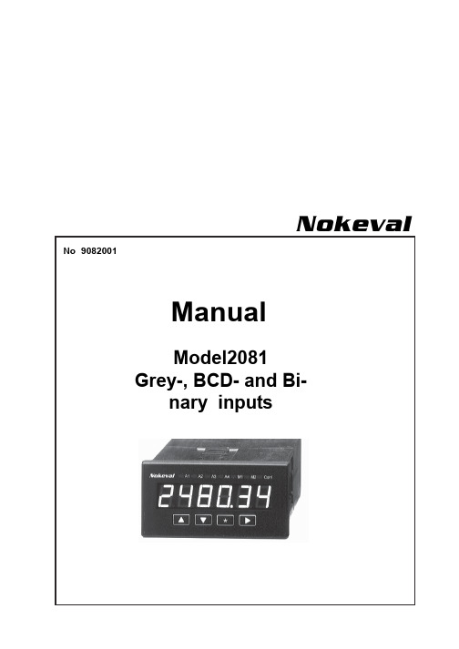
Nokeval No 9082001ManualModel2081Grey-, BCD- and Bi-nary inputsPanel meter 2081 forBCD, Grey and Binary inputs• 5-digit display• Selectable BCD, Grey and Binary inputs • Red or green display• Front panel configuration• Power supply 85..240VAC or 12..32VDC • Front panel protection IP65• Easily changeable for other inputsPanelmeter 2081 is designed for BCD, Grey and Binary coded inputs. Input selection is easy by front panel keys. Two power supply alternatives,85..240 VAC and 12..32 VDC or 24 VAC, both galvanic isolated from inputs. Meter generates 24 VDC, 100 mA power supply for f. ex. PLC’s closing contacts. Selectable pass word for configuration stage. Selectable brightness of display. Front panel protection is IP65.Meter is a part of larger product family, series 2000, and may be changed to other type of meter only by changing input card. Change of input card changes also meter type. Each meter has its own data sheet and instruction manual. Additional,optional cards are the same for all input cards of product family series 2000. Changing of meter type needs no calibrations; only sensor selections and other settings are made by front panel keys.Technical specifications:Display: BCD code -9999..99999 (5 digits)Grey code 0..65535 Binary code 0..65535Display height 14.5 mm Display color Red or green LED, adjustable brightness Input 1 = 5-24 VDV, 0 = <1V Input resistance >10k ΩSupply for input loop 24 VDC, max 150 mA Power 85..240 VAC or 12..32 VDC and 24 VAC Protection IP65, front panel onlyOptional field enclosure 2000IP65Order code 2081GR- BCD2-BCD2-24VDC2081GR green display 2 BCD inputs 2 BCD inputs12..32 VDC, 24VACor 85..240VACBasic meter has 1 BCD-digit and 4 bit Grey- and Binary input. More numbers with optional cards, two in each. Above example has 5BCD-numbers. Standard colour is red unless otherwise specified.Dec.4-bit Binary 4-bit Grey Code Display8 MSB 1 000LSB MSB 1 1 00LSB891 0011 1 01910 1 010 1 1 1110111 0111 1 1011120 10 01 0 101213 1 10 1 1 0 111314 1 11 0 1 0 011415 1 1 11 1 0 0 015Applications:Binary code is simple to use from PLC I/O-lines. Grey-code changes only one bit at a time. Most common Grey code application is angle sensors (aerials etc.)NumberCode Example18, 4, 2, 1 0001= 1 28, 4, 2, 1 0010= 2 38, 4, 2, 1 0011= 3 48, 4, 2, 1 0100= 4 58, 4, 2, 1 0101= 5 68, 4, 2, 1 1001= 9Number 9 in BCD-code is selected as 1001 i.e. 1001 = 8+_+_+1=9BCD-Code➤-button➤-button.➤-button. Text DonE in display Press and hold ★- and ▲-keys simultaneously for 2 seconds.Fix decimal point 0..4, default 0.Choose by ▲▼ -buttons and accept setting by➤-button.Input type selection, default BCD-code.Choose type by ▲▼- keys and accept setting by ➤-button.BCD = BCD-code Bin = Binary-code Garay = Gray-codeMoving into selected menu title.Front panelArrow-buttons(▲▼) are used to change numerical values and when moving in menu-structure.Star-key (★User controllable indicators.Configuration stageConfiguration can be started by pressing and holding ★- and ▲-keys simultaneously for 2seconds.Resetting configuration parametersSome times it is necessary to return indicator parameters to factory defaults, e.g. if secretaccess code is missed. Resetting can be done by pressing and holding ★- and ➤-keys simulta-neously for 2 seconds when connecting supply voltage. Prosedure will reset all settings to factory defaults.Purista kevyesti mittaria etulevun takaa ja vedä eturaamia ulospäinyläreunasta Irroita riviliittimet ja kiinnitysruuviverkkoliittimen vierestä. Irroita etulevy javedä mittari ulos etukautta.avaamalla neljä kulmaruuvia.or 85..240 VAC(Grey connector)The 2000 series panelmeters are modular and easyto assemble. According to customers wishes. Thebasic construction consists of mother board with treeslots, A, B and C. Slot A determines meter type andprovides always input signal. Slot B and C areinterchangeable. As factory delivery input signal isalways installed into slot A , mA output into slot B andalarms into slot C. In case of f.ex 4 alarms and relaycard with 2 change-over contact (2 + 2 relays) areused, you must place second relay card into slot B. IfSlots A-CChange of meter type:Input card is placed always toslot A. By changing input cardyou can get an other type ofmeter. You can change meterwith pulse input to meter withcurrent input, thermocouple,strain gage etc.Additional slots:Additional cards provide output4..20 mA, alarms, serial interface,BCD output etc. Meter data sheetdictates possible combinations.grey connectors allow line voltage110..240 VAC(relay contacts).Power supply:There are two different motherboards power supply85..240VAC and 12..32 VDC.mother board accepts24 VAC. Connectors arecolour coded.you accept only closing or opening relay contacts,you need only one relay card with 4 relays placedinto slot C. The slot B is now usable for otheroptional outputs.You can have different types of meters by onlychanging the input card in slot A. Data sheet of eachtype of meter dictates the possible combinations.Recalibration of card is not needed; only scalingand other settings must be set by front panel keys. memoryRemoving meter from case:Panelmeter 2000 construction。
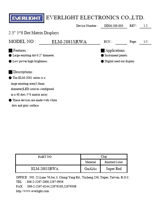
ELM-2081SRWA中文资料
EVERLIGHT ELECTRONICS CO.,LTD.Device Number :DDM-208-003REV: 1.2 2.3" 5*8 Dot Matrix DisplaysMODEL NO :ELM-2081SRWA ECN :Page:1/5█ Features :█ Applications:● Large emitting dot 0.2" diameter.● Instrument panels● Low power/high brightness.● Digital read out display█ Descriptions :● The ELM-2081 series is alarge emitting area(5.0mmdiameter)LED sources configuredin a 40 dots 5*8 matrix array.● These devices are made with whitedots and gray surface.PART NO ChipMaterial Emitted ColorELM-2081SRWA GaAlAs Super RedOFFICE : NO. 25,Lane 76,Sec.3, Chung Yang Rd., Tucheng 236, Taipei, Taiwan, R.O.C.TEL : 886-2-2267-2000,2267-9936FAX : 886-2-2267-6244,22676189,22676306EVERLIGHT ELECTRONICS CO.,LTD.Device Number :DDM-208-003REV: 1.2 2.3" 5*8 Dot Matrix DisplaysMODEL NO :ELM-2081SRWA ECN :Page:2/5█ Notes:1.All dimensions are in millimeters , tolerance is 0.25mm unless otherwide noted.2.Above specification may be changed without notice.Supplier will reserve authority on material change for above specification.EVERLIGHT ELECTRONICS CO.,LTD.Device Number :DDM-208-003REV: 1.2 2.3" 5*8 Dot Matrix DisplaysMODEL NO :ELM-2081SRWA ECN :Page:3/5█Absolute maximum ratings at Ta = 25℃:Parameter Rating UnitReverse Voltage Vr5VForward Current If40mAOperating Temperature Topr-40 to +85℃Storage Temperature Tstg-40 to +100℃Soldering Temperature Tsol260 ± 5℃Power Dissipation Pd110mWPeak Forward Current(Duty1/10 @ 1KHZ)If(Peak)180mA█Electronic optical characteristics :Parameter Symbol MIN.TYP.MAX.Unit Condition Luminous Intensity Iv11.021.9----mcd If=10mAPeak Wavelengthλp----660----nm If=20mADominant Wavelengthλd----643----nm If=20mASpectrum RadiationBandwidth△λ----20----nm If=20mAForward Voltage Vf 1.5 1.7 2.4V If=20mA Reverse Current Ir--------10μA Vr=5VSymbolDevice Number :DDM-208-003REV: 1.2 2.3" 5*8 Dot Matrix DisplaysMODEL NO :ELM-2081SRWA ECN :Page:4/5█ Reliability test items and conditions:NO Item Test Conditions TestHours/CycleSample Size Ac/Re 1Solder Heat TEMP : 260℃ ± 5 ℃ 5 SEC76 PCS0/1H : +85℃ 30min2Temperature Cycle∫ 5 min50 CYCLE76 PCS0/1L : -55℃ 30minH : +100℃ 5min3Thermal Shock∫ 10 sec50 CYCLE76 PCS0/1L : -10℃ 5min4High TemperatureStorageTEMP : 100℃1000 HRS76 PCS0/15Low Temperature Storage TEMP : -55℃1000 HRS76 PCS0/1 6DC Operating Life If = 10 mA1000 HRS76 PCS0/17High Temperature / HighHumidity85℃/85% RH1000 HRS76 PCS0/1Device Number :DDM-208-003REV: 1.2 2.3" 5*8 Dot Matrix DisplaysMODEL NO:ELM-2081SRWA ECN :Page:5/5。
常用背胶基本型号特性汇总
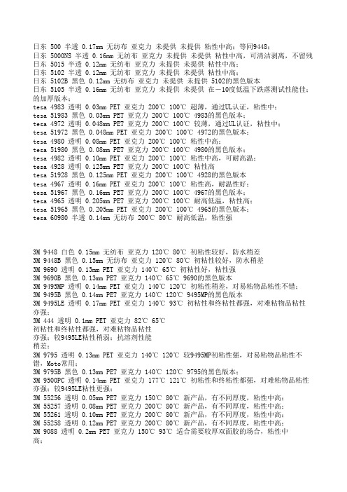
3M9019 厚度:0.03,基材:透明PET,特点与应用:超薄PET胶带,良好的耐热冲击, 特别适合于对厚度 有要求的缓震垫片或LCD 背光模组片材的粘接。
3M9475LE厚度:0.115,基材:透明PET,特点与应用:良好的耐热冲击性及剥离强度。常用于机壳, 塑 料件/金属件的粘接。
3MY9448 厚度:0.15,基材:白色TISSUE,特点与应用:对橡胶,PP,粗糙表面具有较好的粘性。适合于 铭牌/标志粘接, 绝缘片,塑料垫片的粘接。光驱硬盘的减震泡棉的粘接,扫描仪机顶盖泡棉的粘结。 耐温性是-40-80度,
3M9731 厚度:0.140,基材:半透明PET,特点与应用:有机硅双面胶带,适合一面粘接硅树脂,一 面塑料材料的粘接。
3M9460 耐温:短期耐温 260度,长期耐温149摄氏度;具有较高的剪切力、粘着力;具有较好的防 水性能,不受潮湿空气影响;厚度为 0.05 厘米,VHB 胶无色透明,易断。
3M55257 厚度:0.075,基材:透明PET,特点与应用:良好的耐热冲击, 适合泡棉, 元器件, 电池绝缘 体附件等粘接。
3M55258 厚度:0.125,基材:透明PET,特点与应用:优良的耐热冲击及剥离强度, 适合泡棉、元器件、 电池绝缘体附件粘接。
3M55261 厚度:0.1,基材:透明PET,特点与应用:良好的耐热冲击, 适合泡棉, 元器件, 电池绝缘体 附件等粘接。
3M4991 基材 压克力泡棉,厚度 2.3,颜色 灰色,适用范围 广泛应用于油漆喷涂的金属,塑料件的粘接, 较厚的基材能够填充被粘接物之间的空隙,长期耐温93度,短期耐温149度.
ቤተ መጻሕፍቲ ባይዱ
3M55230 厚度:0.15,基材:白色半透明TISSUE、无纺布,耐温性:158℃,特点与应用:较55235厚,剥离
德国蓝天使生态标签 自动关闭电源插排和插座适配器指南说明书

R A T GE B E R Guide togreen public procurement ofContents1.Introduction 42.How to use this guide 53. Scope 54.Applicable laws 65.Environmental requirements 7 5.1.Power consumption 7 5.2Material requirements concerning housing and housing component plastics 75.3Safety requirements 86.Evaluating tenders 8 Annex: Tenderer questionnaire for green public procurement ofauto-off power strips and socket adapters 91. IntroductionPower consumption for avoidable use of device stand-by modes pollutes the envi-ronment and generates unnecessary costs. The use of power strips with manual on-off switches allows two or more devices to be shut off at the same time, including devices that lack a genuine power switch. Experi-ence has shown that manual power strips that can be shut off manually are not used because users find them to be inconven-ient, or manually switchable power strips are not shut off on a regular basis.On the other hand, auto-off power strips en-sure that all devices not in use are switched off. This advantage normally outweighs the drawback that power strips themselves use a minute amount of current.There are two types of power strips:(1) Devices that shut off automatically in the absence of user-configurable minimum power consumption (shutoff threshold) on the part of the master device. When the master device is shut off, the peripheral (slave) devices that are connected to the master device are likewise automatically shut off. These devices are known as mas-ter-slave power strips. (2) Devices which, in the absence of minimum power consumption (shutoff threshold) shut off not only the peripheral devices, but also the master device. This type of device involves no peripheral-de-vice power consumption – in contrast to the idle current used by master-slave power strip master devices. These devices are also made with only one socket, whereby the de-vice plugged into this socket will likewise be shut off.The most advantageous environmental characteristics of eco-friendly auto-off pow-er strips and socket adapters are as follows:•L ower power consumption•M inimization of standby loss•A voidance of materials that pollute the environmentIn view of the fact that auto-off power strips and socket adapters cost more than simple power strips that can be shut off, the pro-curement costing process should factor in the actual estimated advantage of using the more cost intensive solution.2. How to use this guideThis guide contains key information and recommendations for contracting au-thorities concerning the incorporation of environmental aspects into tender and contractual documents. The list of criteria (available from www.beschaffung-info.de) for green public procurement of auto-off power strips and socket adapters should be used as an annex to the specifications. To this end, in terms of the environmen-tal requirements for the contract subject matter in question, you need only include a reference in the specifications in order to meet the legal requirement that the deliver-ables be described clearly and completely.1The tenderer questionnaire is also intended to serve as proof of compliance. The tender wording in this regard could go as follows: In order to be factored into the tender eval-uation process, auto-off power strips and socket adapters must meet the minimum criteria pursuant to the attached tenderer questionnaire on green public procurement of auto-off power strips and socket adapt-ers. By way of proof, you are to submit a completed questionnaire for each tendered product along with the mandated elements of proof.3. ScopeThis guide applies to auto-off power stripsand socket adapters with and without over-load protection.1 Article 7(1) VOL/A and Article 8(1) VOL/A-EG state as follows: “The contractual performance must be describedclearly and exhaustively, so that all candidates must understand the description in the same way and compa-rable tenders can be expected (contractual specifications).” It thus follows from Article 8(5) VOL/A-EG that it is admissible to apply eco-label specifications under certain circumstances. Hence merely referring to these criteria – at least when it comes to the upper threshold domain – is inadmissible. This concept is also supported by a European Court of Justice ruling of 10 May 2012, based on Article 23(6) Directive 2004/18/EU (Case C-368/10 – European Commission ./. Kingdom of the Netherlands (see para. 112).4. Applicable laws•Regulation(EC) No 1272/2008, which governs substance and mixture cate-gorization, labeling and packaging,promulgates a high level of health andenvironmental protection, while stillallowing for free trade of chemicalsubstances, mixtures, and specificproducts and for the improvement ofcompetitiveness and innovation.2•The Globally Harmonized System of Classification and Labeling of Chemi-cals (GHS) supercedes REACH, whichmeans that international regulationsconcerning hazardous-chemical clas-sification, labeling and packaging now also apply in the EU. The GHS aims toensure that hazards are uniformly la-beled worldwide. This in turn promotes free trade and improves safety.3•“REACH” or Regulation (EC) No1907/2006, is the European chemicallaw concerning chemical substanceregistration, evaluation, approval andrestrictions. The law, which came intoeffect in 2007, promulgates a high level of health and environmental protection and also aims to promote free tradeof chemicals within the EU and toimprove competitiveness and innova-tion. REACH is based on the principlethat manufacturers, importers anddownstream users should take respon-sibility for chemicals by ensuring thatthe chemicals that they manufactureand market are used safety. REACHstands for Regulation concerning theRegistration, Evaluation, Authorization and Restriction of Chemicals. REACHis regarded as one of the world’s moststringent chemical laws.42 See Annex VI, part 3, table 3.2 of Regulation (EC) No 1272/2008, available at http://eur-lex.europa.eu/LexUriServ/LexUriServ.do?uri=OJ:L:2008:353:0001:1355:DE:PDF (29 July 2014)[PDF].The currently valid list of harmonized hazardous-substance categories and labels pursuant to Annex 1 of Direc-tive 67/548/EEC (GHS directive), available online at http://www.reach-info.de/ghs_verordnung.htm, (29 July 2014) [html document].The GHS (Global Harmonization System) directive, which came into effect on 20 January 2009, replaces Directives 67/548/EU and 1999/45/EU; it governs substance classification, labeling and packaging until 1 December 2010 pursuant to Directive 67/548/EEC, and until 1 June 2015 governs mixtures in accordance with Directive 1999/45/EU. Contrary to this rule, substances and mixtures can be categorized, labeled and packaged prior to1 December 2010 and 1 June 2015 respectively in accordance with the GHS directive, whereby Directive 67/548/EEC and Directive 1999/45/EEC do not apply in such cases.3 http://www.reach-info.de/ghs_verordnung.htm (7 July 2014) [html document]4 http://www.reach-info.de/einfuehrung.htm#was_ist_das (7 July 2014) [html document]5. Environmental requirements5.1. Power consumption Criterion: MinimumProof of compliance: Manufacturer’s declaration and/or product documenta-tion from the manufacturera) The power consumption of power stripswith overload protection, control lamps and an illuminated on-off switch (ifpresent) is not to exceed 0.9 watts.b) The power consumption of power stripswithout overload protection, but withan illuminated on-off switch (if pres-ent), is not to exceed 0.7 watts.c) The device is to integrate a switchingthreshold function.d) The device is to integrate a powerswitch that cuts off power to the device.The fore-going does not apply to powerstrips which, in the absence of mini-mum power consumption, shut off notonly the peripheral devices, but alsothe master device and each of the vari-ous connected devices. However, suchpower strips are to integrate a wake-up function (via a switch or infraredreceiver, for example) that restores thepower supply.5.2 Material requirementsconcerning housing andhousing componentplasticsCriterion: MinimumProof of compliance: Manufacturer’s declaration•Housing plastics are not to be con-structed of halogen-containing poly-mers such as PVC; nor are chlorine orbromide containing flame retardants to be used as additives in plastic housingcomponents weighing more than 25grams.•Substances that are classified as exhib-iting the following hazardous proper-ties within the meaning of Regulation(EC) No 1272/2008 Annex VI are not to be used in plastic housing components weighing more than 25 grams.•Class 1A and 1B carcinogenic substanc-es•Class 1A and 1B mutagenic substances •Class 1A and 1B reprotoxic substances•Substance of particular concern on any other grounds pursuant to REACH Annex XIII criteria, insofar as suchsubstance is listed in the candidate list in REACH Article 59(1).5.3 Safety requirements Criterion: MinimumProof of compliance: CE mark Auto-off power strips are to bear the CE mark, and thus comply with the following European directives:•2006/95/EU Low Voltage Directive (LVD)•2004/108/EU Electromagnetic Compat-ibility (EMC)6. Evaluating tendersTender evaluations are to factor in contract subject matter related criteria such as en-viron-mental characteristics and life cycle costs.5For the procurement of energy related prod-ucts exceeding the Community thresholds, energy consumption is to be adequately taken into account as a procurement crite-rion.6 This can be done by factoring in life cycle costs7 and/or by evaluating specific power consumption data.8Life cycle costs can be calculated using one of the calculation tools that are available here: https://www.umweltbundesamt.de/en/topics/economics-consumption/ green-procurement/life-cycle-costing.5 See Article 16(8) VOL/A and Article 19(9) VOL/A-EG.6 See Regulation on the Award of Public Contracts (VgV) Article 4(6b).7 For a practical guide to life cycle costing and a list of suitable life cycle costing tools, see the series of Schulungss-kripte titled Umweltfreundliche Beschaffung and therein Einführung in die Berechnung der Lebenszykluskosten und deren Nutzung im Beschaffungsprozess (http://www.umweltbundesamt.de/publikationen/umweltfreundli-che-beschaffung-schulungsskript-5).8 See Article 4(6b) in conjunction with Regulation on the Award of Public Contracts (VgV) Article 6.Annex: Tenderer questionnaire for green public procurement ofauto-off power strips and socket adapters11Guide to auto-off power strips and socket adapters9 Proof of compliance is to be submitted in the guise of the questionnaires in the documents listed under“Comments***********************。
法国尚飞电动卷窗产品手册

灵目50卷窗专用电机 ilmo50卷窗专用电机 灵动50带手动装置有线电机 灵锁50卷窗专用电机 Solus50卷窗专用电机
12V 电池电机
电池电机
·Oximo 40 DC RTS Oximo太阳能电池驱动卷窗电机
请参考卷帘控制方案(参考2-35至2-48页)
4-3 4-4 4-7
4-8 4-9
4-10 4-11 4-13 4-14 4-15
帘体重量
高度 < 1.5m
(kg) 10 20 30 40 50 60 70 80 90 100 110 120 130 140 150 160 170 180 190 200 210 220 230 240 250
(mm)
卷 管
Φ 40
49
Nm Nm
13
Nm
外 径
Φ 49 45 Nm Nm
13
Nm
100
120
89 Nm Nm
Nm
Nm
Nm
Nm
Nm
Nm Nm
Nm
Nm
Nm
Nm
Nm
2.5m < 高度 < 3.5m
(kg) 10 20 30 40 50 60 70 80 90 100 110 120 130 140 150 160 170 180 190 200 210 220 230 240 250 (mm)
尚飞推荐: 电机:Oximo RTS电机:自动限位,限位免维护,中间限位,防上撬; 控制:RTS无线遥控
电动卷窗电机:
无线技术
WT
有线并联技术
有线技术
Oximo50 RTS 电机 LT50 CSI RTS 电机
Oximo50 WT 电机 ilmo50 WT 电机
易维斯 泽尼斯 热升华塑料卡打印机操作手册说明书

FLEXIBILITY• W ith Zenius, you can choose to insert your cards individually or with the automatic feeder.• T he «Expert» version of Zenius features combinable encoding functions: magnetic encoding, contact and contactless chips. It takes just a few minutes to install these modules!EASE OF USE• W ith the Evolis Premium Suite ®software, you can receive notifications and easily control the printer from your computer.• E volis High Trust ® ribbons are easy to install and automatically recognized and set by the printer.SMALL FOOTPRINT• H ardly larger than a standard sheet of paper, Zenius fits perfectly into any environment, be it the office or a customer service counter.• Z enius is an eco-designed printer: very efficient sleep mode and low energy consumption.The Zenius printer is designed for single sided printing and encoding of a very large variety of plastic cards. Zenius generates color or monochrome cards, individually or in small runs, with top quality results. Zenius is a user-friendly, compact and cost-effective solution for delivering your personalized cards.ZENIUSTHE COMPACT AND AGILE CARD PRINTER©2015 Evolis. All rights reserved. Actual product(s) may differ from information stated in this document. All specifications or pictures are subject to change without prior notice. All trademarks mentioned herein belong to their respective owners. Pictures: Olivier Calvez. 07/2015. KB-ZEN1-064-ENG-A4 Rev D0. MK000494EUROPE - MIDDLE-EAST - AFRICAEvolis - 14 avenue de la Fontaine - ZI Angers-Beaucouzé 49070 Beaucouzé - FranceT +33 (0) 241 367 606 - F +33 (0) 241 367 612 - info @AMERICAS - Evolis Inc. - Fort Lauderdale - evolisinc @ ASIA-PACIFIC - Evolis Asia Pte Ltd - Singapore - evolisasia @ CHINA - Evolis China - Shanghai - evolischina @ INDIA - Evolis India - Mumbai - evolisindia @MANUAL OR AUTOMATIC CARD FEEDERGENERAL FEATURES• Direct-to-card dye-sublimation/Resin thermal transfer • Single-sided printing, edge-to-edge • 300 dpi print head (11.8 dots/mm)• 16 million colors• 16 MB memory (RAM)PRINTING PERFORMANCES• C olor (YMCKO): 120 - 150 cards/hour 1• Monochrome: 400 - 500 cards/hourINTERFACES• U SB (1.0, 1.1, 2.0, 3.0), cable supplied • E thernet TCP-IP 10BaseT, 100BaseT (Traffic Led) on the Expert versionCARD MANAGEMENT AND SPECIFICATIONS• A utomatic or manual feeding• Feeder capacity: 50 cards (0.76 mm – 30 mil)• O utput hopper capacity: 20 cards (0.76 mm – 30 mil)• C ard thickness: 0.25 to 0.76 mm (10 to 30 mil), gauge adjustment • C ard types: PVC cards, composite PVC cards, PET cards, ABS cards 1, special varnished cards 1• C ard format: ISO CR80 - ISO 7810 (53.98 mm x 85.60 mm)OPTIONAL FEATURES• C olors available: fire red & grey brown• E xpert version: Ethernet TCP-IP, encoding modules as optionsADDITIONAL ENCODING MODULES•A vailable modules:- Magnetic stripe encoder ISO 7811 HiCo/LoCo, JIS2 - Smart contact station ISO 7816-2- Contact smart card encoder - PC/SC, EMV 2000-1- C ontactless smart card encoder - ISO 14443A, B, ISO15693, MIFARE, DESFire, HID iCLASS - Other specific encoders upon request • I nternal USB or IP ports • O ptions can be combined • F actory-installed or installed on siteSAFETY• S upport for Kensington ® security lock • D ata encryption for magnetic encodingDISPLAY•P rinter LEDs• G raphical notifications from the printer 2: cleaning alerts, empty/low level ribbon and card alerts, etc.EVOLIS HIGH TRUST ® RIBBONSTo maximize the quality and durability of printed cards, the lifespan of the print head and the overall printer reliability, use Evolis High Trust ® ribbons.• A utomatic identification and setting • D elivered in a drop-in cassette for easy handling • R ibbon saver for monochrome printing List of ribbons available on SOFTWARE• D elivered with Evolis Premium Suite ® for Windows ®:- Printer driver - E volis Print Center for administration and settings - Evolis Printer Manager for graphical notification 3 - 24/7 online support - C ompatible with Windows ® (32/64 bits): XP SP3, Vista, W7, W8, W10• D elivered with cardPresso XXS Lite for designing and editing badges:- Internal database up to 50 records- Windows ® (from XP onwards) and Mac OS X • D elivered with a driver for Mac OS X (from 10.5 onwards)• L inux OS upon request • E volis Premium SDK for remote supervision of the printer, while facilitating and speeding up integration into IT systemsECO-FRIENDLY DESIGN, CERTIFICATIONS AND STATEMENT OF COMPLIANCE• S tandby, sleep modes & reduced energy consumption • C E, FCC, IEC, VCCI, CCC, KC, BIS, EAC •R oHSSIZE AND WEIGHT• S ize (H x W x D): 195 x 205 x 315 mm (7.68’’ x 8.07’’ x 12.4’’)• W eight: 3.3 kg (7.3 lbs)WARRANTY• 2-year warranty (printer and print head)4• W arranty extension available as an optionMAIN FEATURES / Full technical specifications on Easy handling, automatic ribbonrecognition and setupW eight: 3.3 kg (3.64 lbs)315 mm (12.4’’)195 mm (7.68’’’)205 mm (8.07’’)1 Under specific conditions /2 Depends on the Windows version /3 Requires the .net 4.0 client profile version4 Warranty subject to observance of specific conditions and use of Evolis High Trust ribbonsALC Technologies Pte LtdBlk 998 Toa Payoh North #07-07/08/09318993 Singapore SingaporeTel : 63541650Fax : 63544595E-mail:*******************Web : 。
供应人体静电消除器
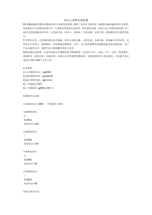
供应人体静电消除器DY-2081触摸式静电消除器也是人体静电消除器。
随着工业经济飞速发展,消除静电越来越显得尤为重要,也是我们不可忽视的重要环节。
人体静电消除器它是采用一种无源式电路,利用人体上的静电使电路工作,最后达到消除静电的作用。
它的特点是:体积小,重量轻。
不需电源。
安装方便。
消除静电时无感觉等特点。
医学研究证实:人体蓄积静电危害健康:有的人皮肤过敏、心律失调、头痛失眠、和烦躁不安等症状,还有的人毛发竖立,精神紧张,害怕接触金属物体。
另外,当人体积蓄静电时触摸电脑会使电脑死机,电子产品元器件击穿,易燃气体点燃和爆炸等重大危害。
触摸式静电消除器,它的外观是由不锈钢管和不锈球制成,它适用于化工、冶金、军工、油田、烟花爆竹、电脑机房、高级宾馆、高级宾馆、高级办公室等易燃易爆场所。
电路原理和其它基本相同,它的最大特点是能在-50~100℃正常工作。
技术指标1).人体静电电压:V≤20KV2).静电释放时间:t≤100mS3).最大释放电流:I≤0.1mA4). 环境温度:20℃5). 环境湿度: ≤80% (40℃)检测条件及结果人体静电电压:18KV 环境温度: 20℃五指释放时间+0.091s残余电压-10V五指释放时间-0.090s残余电压-10V手掌释放时间+0.084s残余电压-9V手掌释放时间-0.082s残余电压-9V安装与使用方法:底座式静电消除球,先把地线接在镙丝上(接地线最好用不小于0.3平方多股导线接到地线的引线上),在球座上有一小孔,把球柱与底座相接好,安装完毕后,如果体内有静电,只需用手指触摸一下上面的金属球0.1s即可消除人体的静电.(指示灯亮一下后熄灭,晚上明显,白天不明显.)如果体内静电小于100V或没有静电,静电指示灯则不亮。
无底座式静电消除球:首先将球体静电消除器一头埋入地下至少需要200mm,另一头球体朝上,这样就安装完毕了。
维护保养:钢管内不进入杂物,特别是金属物,因为内有电路原件,如果进入金属物电路不能正常工作。
E1UAA20-16.257M中文资料(ECLIPTEK)中文数据手册「EasyDatasheet - 矽搜」
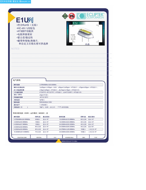
E1U列•符合RoHS(无铅)•HC-49 / US短包•AT或BT切提供•电阻焊接密封•紧公差/稳定性•磁带和卷轴,绝缘片,和自定义引线长度可供选择NOTES H 2.50L 11.18W 4.70水晶_____________________________________________________________________________________________________________________________________________________________________________________________ _____________________________________________________________________________________________________________________________________________________________________________________________ _____________________________________________________________________________________________________________________________________________________________________________________________ _____________________________________________________________________________________________________________________________________________________________________________________________ _____________________________________________________________________________________________________________________________________________________________________________________________ _____________________________________________________________________________________________________________________________________________________________________________________________ _____________________________________________________________________________________________________________________________________________________________________________________________ _____________________________________________________________________________________________________________________________________________________________________________________________ _____________________________________________________________________________________________________________________________________________________________________________________________ _____________________________________________________________________________________________________________________________________________________________________________________________ _____________________________________________________________________________________________________________________________________________________________________________________________ _____________________________________________________________________________________________________________________________________________________________________________________________电气特性频率范围频率公差/稳定性在工作温度范围温度范围工作温度范围老化(25°C)存储温度范围并联电容绝缘电阻驱动电平负载电容(C)3.579545MHz为50.000MHz为±50ppm /±100ppm(标准),±30ppm/为±50ppm(AT切割只),±15ppm/±30ppm(AT切割只),±15ppm/±20ppm(AT切割只),或±10ppm/±15ppm(AT切割专用)0°C到70°C,-20°C至70°C(AT切割只),或-40°C至85°C(AT切割专用)±5ppm/年最大-40°C至125°C7pF最大500兆欧最低在100V1 mWatt最大18pF之(标准),自定义C 10pF,或串联谐振等效串联电阻(ESR),运作模式(MODE),切频率范围3.579545MHz到4.999MHz5.000MHz到5.999MHz6.000MHz到7.999MHz8.000MHz到8.999MHz9.000MHz到9.999MHz10.000MHz到14.999MHz ESR (Ω)200最大150最大120最大90马克斯80马克斯70马克斯模式/剪切基本/ AT基本/ AT基本/ AT基本/ AT基本/ AT基本/ AT频率范围15.000MHz到15.999MHz16.000MHz到23.999MHz24.000MHz到30.000MHz24.000MHz到40.000MHz24.576MHz为29.999MHz30.000MHz到50.000MHzESR (Ω)60马克斯50马克斯40马克斯40马克斯150最大100最大模式/剪切基本/ AT基本/ AT基本/ AT基本/ BT三次泛音/ AT三次泛音/ AT.ECLIPTEK CORP.CRYSTAL E1U HC-49/US Short CR4111/07零件编码指南E1U A A 18 - 20.000M - I2 TR频率公差/稳定性A =±50PPM 25°C时,±0℃至100ppm70℃B =±50PPM,在25°C,±100ppm-20℃至70℃C =±50PPM,在25°C,±100ppm温度范围为-40°C至85°CD =±30ppm25°C时,±0℃50PPM至70℃E =±30ppm25°C时,为±50ppm -20℃至70℃F =±30ppm25°C时,为±50ppm -40°C至85°CG =±15ppm25°C时,±0℃为30ppm至70℃H =±15ppm25°C时,±30ppm-20℃至70℃J =±15ppm25°C时,±30ppm温度范围为-40°C至85°C K =±15ppm25°C时,±0℃为20ppm至70℃L =±15ppm25°C时,±20ppm-20℃至70℃M =±15ppm25°C时,±20ppm温度范围为-40°C至85°C N =±10ppm25°C时,±0℃为15ppm至70℃P =±10ppm25°C时,±15ppm-20℃至70℃包装选择空白=散装,A =盘,TR =卷带式可选项空白=无(标准)CX =自定义引线长度I2 =绝缘子标签频率负载电容S =系列X X = X X pF(自定义)动作模式/水晶切割A =基本/ A TB =三次泛音/ A TD =基本/ BT外形尺寸ALL DIM ENSIONS IN M ILLIM ET ERS 卷带尺寸ALL DIM ENSIONS IN M ILLIM ET ERS环境/机械特性PARAMET ER SPECIFICAT ION 标记规格1000 Pieces per ReelCompliant to EIA-468B精细泄漏测试总泄漏测试铅完整铅端接机械冲击耐焊接热抗溶剂可焊性温度循环振荡M IL-STD-883,方法1014,条件AM IL-STD-883,方法1014,条件CM IL-STD-883 2004方法锡2微米 - 6微米M IL-STD-202,方法213,条件CM IL-STD-202,方法210M IL-STD-202,方法215M IL-STD-883,2002年法M IL-STD-883,法1010M IL-STD-883,方法2007,条件A1号线:电子X X.X X X中号Frequency in MHz(5 Digits Maximum + Decimal).ECLIPTEK CORP.CRYSTAL E1U HC-49/US Short CR4111/07。
- 1、下载文档前请自行甄别文档内容的完整性,平台不提供额外的编辑、内容补充、找答案等附加服务。
- 2、"仅部分预览"的文档,不可在线预览部分如存在完整性等问题,可反馈申请退款(可完整预览的文档不适用该条件!)。
- 3、如文档侵犯您的权益,请联系客服反馈,我们会尽快为您处理(人工客服工作时间:9:00-18:30)。
EVERLIGHT ELECTRONICS CO.,LTD.
Device Number :DDM-208-004REV: 1.1 2.3" 5*8 Multi-Color Dot Matrix Display
MODEL NO :ELM-2081EGWA ECN :Page:1/5
█ Features :█ Applications:
● Large emitting dot0.2"diameter.● Instrument panels
● Low power/high brightness.● Digital read out display
█ Descriptions :
● The ELM-2081 series are a
large emitting area(5.0mm
diameter)LED sources configured
in a 40 dots 5*8 matrix array.
● These device is made with white
dots and gray surface.
PART NO CHIP C.C. or C.A.
Material Emitted Color
E GaAsP/GaP Orange
ELM-2081EGWA G GaP Green C.C.
OFFICE : NO. 25,Lane 76,Sec.3, Chung Yang Rd., Tucheng 236, Taipei, Taiwan, R.O.C.
TEL : 886-2-2267-2000,2267-9936
FAX : 886-2-2267-6244,22676189,22676306
EVERLIGHT ELECTRONICS CO.,LTD.
Device Number :DDM-208-004REV: 1.1 2.3" 5*8 Multi-Color Dot Matrix Display
MODEL NO :ELM-2081EGWA ECN :Page:2/5
█ NOTES:
1.All dimensions are in millimeters ,tolerance is 0.25mm unless otherwise noted.
2.Above specification may be changed without notice.
Supplier will reserve authority on material change for above specification.
EVERLIGHT ELECTRONICS CO.,LTD.
Device Number :DDM-208-004REV: 1.1 2.3" 5*8 Multi-Color Dot Matrix Display
MODEL NO :ELM-2081EGWA ECN :Page:3/5█Absolute maximum ratings at Ta = 25℃:
Parameter Symbol Rating Unit
Reverse Voltage Vr5V
Forward Current If30mA
Operating Temperature Topr-40 to +85℃
Storage Temperature Tstg-40 to +100℃
Soldering Temperature Tsol260 ± 5℃
Power Dissipation Pd100mW
Peak Forward
Current(Duty 1/10 @
1KHZ)
If(Peak)160mA
█Electronic optical characteristics :
Parameter Symbol MIN.TYP.MAX.Unit Condition Luminous Intensity Iv E 2.2 3.4----mcd If=10mA
G 2.6 4.0----
Peak Wavelengthλp E----635----nm If=20mA
G----565----
Dominant Wavelengthλd E----625----nm If=20mA
G----570----
Spectrum Rediation
Bandwidth△λE ----45----
nm If=20mA
G
----30----
Forward Voltage Vf E 1.7 2.0 2.4V If=20mA
G 1.7 2.1 2.4
Reverse Current Ir--------10µA Vr=5V
EVERLIGHT ELECTRONICS CO.,LTD.
Device Number :DDM-208-004REV: 1.1 2.3" 5*8 Multi-Color Dot Matrix Display
MODEL NO :ELM-2081EGWA ECN :Page:4/5█ Reliability test item and condition:
NO Item Test Conditions
Test
Hours/Cycle
Sample Size Ac/Re
1Solder Heat TEMP : 260℃ ± 5 ℃ 5 SEC76 PCS0/1
H : +85℃ 30min
2Temperature Cycle∫ 5 min50 CYCLE76 PCS0/1
L : -55℃ 30min
H : +100℃ 5min
3Thermal Shock∫ 10 sec50 CYCLE76 PCS0/1
L : -10℃ 5min
4High Temperature
Storage
TEMP : 100℃1000 HRS76 PCS0/1
5Low Temperature Storage TEMP : -55℃1000 HRS76 PCS0/1 6DC Operating Life If = 10 mA1000 HRS76 PCS0/1
7High Temperature / High
Humidity
85℃/85% RH1000 HRS76 PCS0/1
EVERLIGHT ELECTRONICS CO.,LTD.
Device Number :DDM-208-004REV: 1.1 2.3" 5*8 Multi-Color Dot Matrix Display
MODEL NO:ELM-2081EGWA ECN :Page:5/5。
