Ppi通讯协议
PPI协议详解 ppi通讯协议 ppi通信协议 vb与ppi协议通讯
PPI协议详解 ppi通讯协议 ppi通信协议vb与ppi协议通讯PPI协议详解一、引言PPI(Parallel Peripheral Interface)协议是一种用于并行通信的通讯协议,用于连接VB(Visual Basic)与外部设备之间的通信。
本文将详细介绍PPI协议的结构、通信方式、命令格式等内容,以帮助读者全面了解PPI协议的工作原理和使用方法。
二、PPI协议结构PPI协议采用主从结构,由一个主站(VB)和一个或多个从站(外部设备)组成。
主站负责发送命令和接收数据,从站负责接收命令和发送数据。
三、PPI协议通信方式PPI协议支持两种通信方式:同步通信和异步通信。
1. 同步通信在同步通信模式下,主站和从站之间的数据传输是同步进行的。
主站发送一个命令后,等待从站回应后再发送下一个命令。
这种通信方式适用于对实时性要求较高的应用场景。
2. 异步通信在异步通信模式下,主站和从站之间的数据传输是异步进行的。
主站可以连续发送多个命令,而无需等待从站的回应。
从站在接收到命令后,会立即执行,并将执行结果返回给主站。
这种通信方式适用于对实时性要求不高的应用场景。
四、PPI协议命令格式PPI协议的命令格式包括头部和数据部分。
1. 头部头部包括起始字节、目的地址、源地址和命令字等字段。
起始字节用于标识数据包的开始,目的地址和源地址用于指定通信的主从站,命令字用于指定具体的操作。
2. 数据部分数据部分用于传输实际的数据。
数据的格式和长度根据具体的应用场景而定,可以是数字、字符串、图像等。
五、PPI协议通信流程PPI协议的通信流程如下:1. 主站发送命令主站向从站发送命令,命令中包括具体的操作和参数。
2. 从站执行命令从站接收到命令后,执行相应的操作,并将执行结果返回给主站。
3. 主站接收结果主站接收从站返回的执行结果,并进行相应的处理。
4. 重复以上步骤根据具体的应用需求,主站可以继续发送命令,从站继续执行,并返回执行结果。
PPI协议详解 ppi通讯协议 ppi通信协议 vb与ppi协议通讯

PPI协议详解 ppi通讯协议 ppi通信协议vb与ppi协议通讯PPI协议详解一、引言PPI(Point-to-Point Interface)是一种用于工业自动化领域的通信协议,用于实现PLC(Programmable Logic Controller)与外部设备之间的数据交换。
本文将详细介绍PPI协议的基本原理、通信方式以及相关参数设置。
二、协议概述1. PPI协议是一种点对点的通信协议,即一台PC机与一台PLC之间建立一对一的通信连接。
2. PPI协议采用串行通信方式,使用RS485物理层接口进行数据传输。
3. PPI协议支持数据的读取和写入操作,可以实现PLC与PC机之间的双向数据交换。
三、通信协议1. 物理层接口:PPI协议使用RS485物理层接口,通过两根数据线(D+和D-)进行数据传输。
2. 通信速率:PPI协议支持多种通信速率,常见的有9.6Kbps、19.2Kbps、187.5Kbps等。
3. 数据帧格式:PPI协议的数据帧由起始位、数据位、校验位和停止位组成,其中校验位可以选择奇校验、偶校验或无校验。
4. 通信模式:PPI协议支持主从模式和从从模式两种通信模式。
在主从模式下,PC机作为主站发送指令,PLC作为从站接收指令并返回响应;在从从模式下,PC机和PLC都可以发送指令和接收响应。
四、通信过程1. 主站发送指令:PC机作为主站发送指令到PLC。
指令包括命令码、数据和校验位等信息。
2. 从站接收指令:PLC作为从站接收主站发送的指令,并进行校验。
3. 从站执行指令:PLC根据接收到的指令进行相应的操作,如读取数据、写入数据等。
4. 从站返回响应:PLC将执行结果返回给主站,包括数据、状态信息等。
5. 主站接收响应:PC机作为主站接收从站返回的响应,并进行校验。
6. 数据处理:PC机对接收到的数据进行解析和处理,如显示在界面上、保存到文件中等。
五、参数设置1. 通信地址:PLC和PC机之间需要设置通信地址,确保能够正确建立通信连接。
ppi通讯协议
ppi通讯协议PPI通讯协议。
PPI(Parallel Printer Interface)通讯协议是一种并行打印机接口协议,广泛应用于计算机和打印机之间的数据传输。
PPI通讯协议的出现,极大地方便了用户对打印机的操作,使得打印工作更加高效和便捷。
本文将对PPI通讯协议的原理、特点及应用进行介绍,希望能为大家对PPI通讯协议有更深入的了解。
PPI通讯协议的原理是通过并行接口将计算机和打印机连接起来,实现数据的传输和打印功能。
在PPI通讯协议中,数据是以并行的方式进行传输的,这意味着多位数据同时进行传输,因此在传输速度上具有一定的优势。
同时,PPI通讯协议还采用了特定的数据格式和传输协议,保证了数据的准确性和稳定性,从而确保了打印质量。
PPI通讯协议的特点主要体现在以下几个方面,首先,PPI通讯协议具有较高的传输速度,能够满足大部分打印需求;其次,PPI通讯协议的稳定性较好,不容易出现数据传输错误或丢失的情况;再次,PPI通讯协议的适用范围广泛,几乎可以适配所有类型的打印机;最后,PPI通讯协议的成本相对较低,适合大规模应用。
在实际应用中,PPI通讯协议被广泛应用于各类打印机设备中,包括激光打印机、喷墨打印机、针式打印机等。
通过PPI通讯协议,计算机可以向打印机发送打印任务,并控制打印机进行打印操作。
同时,PPI通讯协议也为打印机的开发和生产提供了技术支持,使得打印机能够更好地与计算机进行通讯和协作。
总的来说,PPI通讯协议作为一种并行打印机接口协议,在计算机和打印机之间起着至关重要的作用。
它的出现极大地方便了用户对打印机的操作,提高了打印效率,同时也推动了打印技术的发展。
随着科技的不断进步,PPI通讯协议也在不断演进和完善,带来了更多的新功能和应用场景。
在未来,随着打印技术的不断发展和普及,PPI通讯协议将继续发挥重要作用,为用户提供更加便捷和高效的打印体验。
相信通过我们的努力,PPI通讯协议将会在未来的科技发展中发挥更加重要的作用,为人们的生活带来更多的便利和惊喜。
PPI协议详解 ppi通讯协议 ppi通信协议 vb与ppi协议通讯
PPI协议详解 ppi通讯协议 ppi通信协议vb与ppi协议通讯PPI协议详解一、引言本文旨在详细解释PPI协议(Programmable Peripheral Interface Protocol,可编程外设接口协议)的相关内容,包括ppi通讯协议和ppi通信协议。
同时,本文还将介绍VB与PPI协议通讯的相关内容。
二、PPI通讯协议概述PPI通讯协议是一种用于编程控制外设的通讯协议。
它定义了外设与主控设备之间的数据交换方式和通信规则。
PPI通讯协议的主要特点包括:1. 数据格式:PPI通讯协议规定了数据的格式,包括数据的位数、字节顺序等。
2. 通信速率:PPI通讯协议规定了通信的速率,即数据传输的速度。
3. 错误检测和纠正:PPI通讯协议提供了错误检测和纠正的机制,以确保数据传输的可靠性。
三、PPI通信协议详解PPI通信协议是一种用于编程控制外设之间通信的协议。
它定义了外设之间的数据传输方式和通信规则。
PPI通信协议的主要特点包括:1. 数据传输方式:PPI通信协议规定了数据的传输方式,包括同步传输和异步传输。
2. 数据帧结构:PPI通信协议规定了数据帧的结构,包括起始位、数据位、校验位等。
3. 控制信号:PPI通信协议定义了用于控制数据传输的各种信号,如使能信号、时钟信号等。
四、VB与PPI协议通讯VB(Visual Basic)是一种常用的编程语言,用于开发Windows应用程序。
与PPI协议通讯可以实现VB程序与外设之间的数据交换。
在VB与PPI协议通讯中,需要注意以下几点:1. 引入PPI库:在VB程序中,需要引入PPI库以便使用PPI协议相关的函数和方法。
2. 初始化PPI:在与外设通讯之前,需要初始化PPI协议,包括设置通信速率、数据格式等。
3. 数据交换:通过调用PPI库提供的函数和方法,可以实现与外设的数据交换。
4. 错误处理:在与外设通讯过程中,可能会出现错误。
需要进行适当的错误处理,以确保数据传输的可靠性。
PPI协议详解 ppi通讯协议 ppi通信协议 vb与ppi协议通讯
PPI协议详解 ppi通讯协议 ppi通信协议vb与ppi协议通讯PPI协议详解PPI通讯协议,也称为PPI通信协议,是一种用于在VB与PPI设备之间进行通讯的协议。
本文将详细介绍PPI协议的工作原理、通讯方式、数据格式以及通讯流程等内容。
一、PPI协议的工作原理PPI协议是一种基于并行通讯的协议,它通过并行数据线和控制线实现数据的传输和控制。
PPI设备通常是指PLC(可编程逻辑控制器)等工业自动化设备,而VB则是一种常用的编程语言。
二、PPI协议的通讯方式PPI协议支持两种通讯方式:主从式和点对点式。
1. 主从式通讯在主从式通讯中,VB作为主站(Master),而PPI设备作为从站(Slave)。
主站负责发起通讯请求,从站则负责响应请求并返回数据。
2. 点对点式通讯在点对点式通讯中,VB与PPI设备之间直接进行通讯,没有主从之分。
数据的传输是双向的,VB可以向PPI设备发送指令,并接收设备返回的数据。
三、PPI协议的数据格式PPI协议使用二进制数据进行通讯,数据的格式包括帧头、数据区和帧尾。
1. 帧头帧头用于标识一帧数据的开始,通常由几个特定的字节组成。
帧头的作用是告诉接收方数据的开始位置,以便接收方正确解析数据。
2. 数据区数据区是PPI协议中最重要的部分,它包含了具体的通讯数据。
数据区的长度可以根据实际需求进行变化,但通常不超过256字节。
3. 帧尾帧尾用于标识一帧数据的结束,通常由一个或多个特定的字节组成。
帧尾的作用是告诉接收方数据的结束位置,以便接收方正确解析数据。
四、PPI协议的通讯流程PPI协议的通讯流程包括连接建立、数据传输和连接关闭三个阶段。
1. 连接建立在连接建立阶段,VB需要与PPI设备建立通讯连接。
具体的连接方式可以根据实际需求选择,例如串口通讯、以太网通讯等。
2. 数据传输在数据传输阶段,VB可以向PPI设备发送指令,并接收设备返回的数据。
数据的传输方式可以是主动轮询、中断驱动或事件驱动等。
PPI协议详解 ppi通讯协议 ppi通信协议 vb与ppi协议通讯
PPI协议详解 ppi通讯协议 ppi通信协议vb与ppi协议通讯PPI协议详解1. 介绍PPI(Point-to-Point Interface)是一种用于工业自动化系统的通信协议,用于连接编程设备(如PC)与可编程逻辑控制器(PLC)之间的通信。
本协议旨在提供高效可靠的数据传输,使得编程设备能够与PLC进行数据交换和远程控制。
2. 协议结构PPI协议采用点对点的通信方式,分为物理层和数据链路层两部分。
2.1 物理层PPI协议使用RS485总线作为物理层传输介质,具有抗干扰能力强、传输距离远等特点。
编程设备和PLC通过RS485接口进行连接,其中编程设备作为主站,PLC作为从站。
2.2 数据链路层数据链路层负责数据的传输和错误检测。
PPI协议将数据分为帧进行传输,每帧由起始符、地址、数据、校验和等字段组成。
2.2.1 帧结构PPI协议的帧结构如下:起始符 | 地址 | 数据 | 校验和起始符:用于标识一帧数据的开始,通常为0x68。
地址:指定PLC的地址,用于区分不同的PLC。
数据:包含要发送或接收的数据。
校验和:用于检测数据传输过程中是否出现错误。
2.2.2 数据传输编程设备通过发送帧给PLC来传输数据,PLC接收到帧后进行处理,并可以返回响应帧给编程设备。
数据传输的过程中,编程设备和PLC通过交替发送和接收帧的方式进行通信。
3. PPI通讯协议PPI通讯协议定义了编程设备与PLC之间的通信规则和消息格式,包括数据读写、寄存器访问、程序控制等功能。
3.1 数据读写编程设备可以通过PPI通讯协议向PLC写入数据或读取数据。
写入数据时,编程设备发送写入命令帧给PLC,并携带要写入的数据。
读取数据时,编程设备发送读取命令帧给PLC,并等待PLC返回响应帧,响应帧中包含要读取的数据。
3.2 寄存器访问PPI通讯协议定义了一系列寄存器,用于存储和访问PLC的状态信息、输入输出信号等。
编程设备可以通过读写命令访问这些寄存器,实现对PLC的状态监测和控制。
PPI MPI Profibus 通信协议详解
1、MPI是Multi-Point Interface,适用于PLC 200/300/400、操作面板TP/OP及上位机MPI/PROFIBUS通信卡,MPI网络的通信速率为网络才支持12Mbit/s的通信速率。
MPI网络最多可以连接32个接节点,最大通信距离为50m,但是可以通过中继器来扩展长度。
PPI协议是专门为S7-200开发的通信协议。
S7-200 CPU的通信口(Port0、Port1)支持PPI通信协议,S7-200的一些通信模块也支持PPI协议。
Micro/WIN与CPU进行编程通信也通过PPI协议。
PPI是一种主从协议,主站、从站在一个令牌网。
在一个PPI网络中,与一个从站通信的主站的个数并没有限制,但是一个网络中主站的个数不能超过32个。
主站既可以读写从站的数据,也可以读写主站的数据。
也就是说,S7-200作为PPI主站时,仍然可以作为从站响应其他主站的数据请求。
MPI是主站之间的通信;PPI可以是多台主站与从站之间通信。
2、MPI协议:西门子内部协议,不公开;PROFIBUS-DP协议:标准协议,公开。
3、MODBUS 是MODICON公司最先倡导的一种软的通讯规约,经过大多数公司的实际应用,逐渐被认可,成为一种标准的通讯规约,只要按照这种规约进行数据通讯或传输,不同的系统就可以通讯。
目前,在RS232/RS485通讯过程中,更是广泛采用这种规约。
常用的MODBUS 通讯规约有两种,一种是MODBUS ASCII,一种是MODBUS RTU。
一般来说,通讯数据量少而且主要是文本的通讯则采用MODBUS ASCII规约,通讯数据数据量大而且是二进制数值时,多采用MODBUS RTU规约。
在实际的应用过程中,为了解决某一个特殊问题,人们喜欢自己修改MODBUS规约来满足自己的需要(事实上,人们经常使用自己定义的规约来通讯,这样能解决问题,但不太规范)。
更为普通的用法是,少量修改规约,但将规约格式附在软件说明书一起,或直接放在帮助中,这样就方便了用户的通讯。
机电一体化(PPI通信)

远程站上被访问的数据区的长度 接收或发送数据区:共16字节大小,接收或发 送的数据大小,由数据长度字节决。 对NETR指令,执行后,从远程站读到的数据 存放在这个区域;对NETW指令,执行后,要 发送到远程站的数据存放在这个区域。
③状态字节各位意义
Bit7:操作完成位。0:未完成,1:已完成 Bit6:有效位,操作已被排队。0:无效,1:有效。 Bit5:错误标志位。0:无效,1:有效。 Bit4:未用 Bit3、Bit 2、 Bit 1、Bit 0:错误码,如果执行读写指令后Bit5为1,则由该 4位组成一个错误码。 错误码的意义如下: 0000:无错误 0001:时间溢出错误,远程站点不响应 0010:接收错误:寄偶校验错 0011:离线错误:相同的站地址或无效的硬件引发冲突 0100:队列溢出错误:激活了超过8个NETR和NETW指令。 0101:没有在SMB30中允许PPI协议而执行网络指令 0110:非法参数,NETR和NETW指令中包含非法或无效值。 0111:没有资源:远程站点正在忙中 1000:第7层错误,违反应用协议 1001:信息错误:错误的数据地址或不正确的数据长度。 1010-1111:未用。
习题二 两台PLC分别控制两台电动机,1#PLC为主 机,控制1M电动机,站地址2;2#PLC为从 机,控制2M电动机,站地址为4。1M电动机 能够连续和点动运行,其控制由2#PLC输入 信号实现;2M电动机采取星角启动控制,其 控制信号由1#PLC提供。两台PLC间采用PP 通信。 用指令和向导法两种方法编写主从程序并调 试
3、端口控制字节各位意义
位址 代表符号 Bit7 p Bit6 p Bit5 d Bit4 b Bit3 b Bit2 b Bit1 m Bit0 m
pp:校验选择 00=不校验 01=偶校验 10=不校验 11=寄校验
PPI协议
PPI协议
PPI通讯协议SIEMENS专为s7-200plc开发的通信协议。
是一种主从协议,主站发送要求到从站,从站响应。
默认情况下,s7-200cpu工作在PPI从站模式,要执行网络读写指令,必须用程序吧CPU设置为PPI主站模式,此时可以利用网络读写指令读写其他的PLC,也可以响应其他主站的申请。
网络读指令NETR、网络写指令NETW格式为:
NETR TBL,PORT //TBL;VB,MB
NETW TBL,PORT //PORT;0,1
PPI协议可以运行在多种类型的串口网络上,包括COM、USB、以太网等。
而“PPI接口”只是一种习惯称谓,不规范,但是业内都能理解。
严格的讲应该是“执行PPI协议的通讯接口”。
在S7-200中,PPI接口多指PLC上的PORT(RS485标准),其默认状态下是执行PPI 协议的;如果将其设置为自由口模式,则成为普通的RS485接口,可以执行用户指定的通讯协议。
最新PPI MPI Profibus 通信协议详解

1、 MPI是Multi-Point Interface,适用于PLC 200/300/400、操作面板TP/OP 1及上位机MPI/PROFIBUS通信卡,MPI网络的通信速率为网络才支持12Mbit/s的2通信速率。
MPI网络最多可以连接32个接节点,最大通信距离为50m,但是可以3通过中继器来扩展长度。
4PPI协议是专门为S7-200开发的通信协议。
S7-200 CPU的通信口(Port0、5Port1)支持PPI通信协议,S7-200的一些通信模块也支持PPI协议。
Micro/WIN 6与CPU进行编程通信也通过PPI协议。
PPI是一种主从协议,主站、从站在一个7令牌网。
在一个PPI网络中,与一个从站通信的主站的个数并没有限制,但是一8个网络中主站的个数不能超过32个。
主站既可以读写从站的数据,也可以读写9主站的数据。
也就是说,S7-200作为PPI主站时,仍然可以作为从站响应其他10主站的数据请求。
1112MPI是主站之间的通信;PPI可以是多台主站与从站之间通信。
13142、MPI协议:西门子内部协议,不公开;15PROFIBUS-DP协议:标准协议,公开。
16173、MODBUS 是MODICON公司最先倡导的一种软的通讯规约,经过大多数公司18的实际应用,逐渐被认可,成为一种标准的通讯规约,只要按照这种规约进行数19据通讯或传输,不同的系统就可以通讯。
目前,在RS232/RS485通讯过程中,更20是广泛采用这种规约。
21常用的MODBUS 通讯规约有两种,一种是MODBUS ASCII,一种是MODBUS RTU。
22一般来说,通讯数据量少而且主要是文本的通讯则采用MODBUS ASCII规约,23通讯数据数据量大而且是二进制数值时,多采用MODBUS RTU规约。
24在实际的应用过程中,为了解决某一个特殊问题,人们喜欢自己修改MODBUS 25规约来满足自己的需要(事实上,人们经常使用自己定义的规约来通讯,这样能26解决问题,但不太规范)。
S7200_PPI通信协议

S7-200 PPI通信协议PPI通信协议是一种主从式的通信协议,上位机即PC机为主,PLC为从。
通信开始由运算机发起,PLC予以响应。
1)、运算机按通信赖务,用必然格式,向PLC发送通信命令。
2)、PLC收到命令后,进行命令校验,如无误,那么向运算机发送数据E5H或F9H,作出初步应答。
3)、运算机收到初步应答后,再向PLC发送SD DA SA FC FCS ED确认命令。
那个地址,SD为起始字符,为10H;DA为目的,即PLC地址02H;SA为数据源,即运算机地址00H;FC为功能码,取5CH;FCS为SA、DA、FC和的256余数,为5EH;末字节ED为终止符,也是16H。
如按以上设定的运算机及PLC地址,那么发送10、02、00、5C、5E、及16,6个字节的十六进制数据,以确认所发命令。
4)、PLC收到此确认后,执行运算机所发送的通信命令,并向运算机返回相应数据。
它的通信进程要往复两次才完成一次的通信,比较麻烦,但较严谨,不易犯错。
SD LE LER SD DA SA FC DASP SSAP DU FCS EDSD:(Start Delimiter)开始定界符,占1字节,为68HLE:(Length)报文数据长度,占1字节,标明报文以字节计,从DA到DU的长度;LER:(Repeated Length)重复数据长度,同LESD: (Start Delimiter)开始定界符(68H)DA:(Destination Address)目标地址,占1字节,指PLC在PPI上地址,一台PLC时,一样为02,多台PLC 时,那么各有各的地址;SA:(Source Address)源地址,占1字节,指运算机在PPI上地址,一样为00;FC:(Function Code)功能码,占1字节,6CH一样为读数据,7CH一样为写数据DSAP:(Destination Service Access Point)目的效劳存取点,占多个字节SSAP:(Source Service Access Point)源效劳存取点,占多个字节DU:(Data Unit)数据单元,占多个字节FCS:(Frame Check Sequence)占1字节,从DA到DU之间的校验和的256余数;ED:(End Delimiter)终止分界符,占1字节,为16H命令类型1)读命令读命令长度都是33个字节。
西门子PLC几种常见的连接口和通讯协议

西门子PLC几种常见的连接口和通讯协议第一个大问题:RS232接口与RS485接口的区别一、接口的物理结构1、RS232接口:计算机通讯接口之一,通常 RS-232 接口以9个引脚 (DB-9) 或是25个引脚 (DB-25) 的型态出现,一般个人计算机上会有两组 RS-232 接口,分别称为 COM1 和 COM2。
2、RS485RS485无具体的物理形状,根据工程的实际情况而采用的接口。
二、接口的电子特性1、RS232:传输电平信号接口的信号电平值较高(信号“1”为“-3V至-15V”,信号“0”为“3至15V”),易损坏接口电路的芯片,又因为与TTL电平(0~“<0.8v”,1~“>2.0V”)不兼容故需使用电平转换电路方能与TTL电路连接。
另外抗干扰能力差。
2、RS485:传输差分信号逻辑“1”以两线间的电压差为+(2—6)V表示;逻辑“0”以两线间的电压差为-(2—6)V表示。
接口信号电平比RS-232降低了,就不易损坏接口电路的芯片,且该电平与TTL电平兼容,可方便与TTL电路连接。
三、通讯距离长短1、RS232:RS232传输距离有限,最大传输距离标准值为15米,且只能点对点通讯,最大传输速率最大为20kB/s。
2、RS485:RS485最大无线传输距离为1200米。
最大传输速率为10Mbps,在100Kb/S的传输速率下,才可以达到最大的通信距离。
采用阻抗匹配、低衰减的专用电缆可以达到1800米!超过1200米,可加中继器(最多8只),这样传输距离接近10Km。
四、能否支持多点通讯RS232:RS232接口在总线上只允许连接1个收发器,不能支持多站收发能力,所以只能点对点通信,不支持多点通讯。
RS485:RS485接口在总线上是允许连接多达128个收发器。
即具有多站通讯能力,这样用户可以利用单一的RS485接口方便地建立起设备网络。
五、通讯线的差别RS232:可以采用三芯双绞线、三芯屏蔽线等。
PPI通讯读写协议
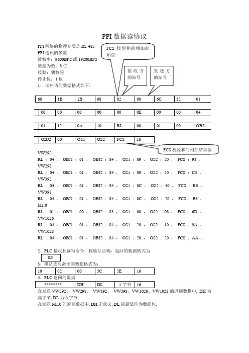
RL :04 ,OBJ1 :01 ,OBJ2 :84 ,OS1 :09 ,OS2 :20 ,FCS :93 。
VW298RL :04 ,OBJ1 :01 ,OBJ2 :84 ,OS1 :09 ,OS2 :50 ,FCS :C3 。
VW392RL :04 ,OBJ1 :01 ,OBJ2 :84 ,OS1 :0C ,OS2 :40 ,FCS :B6 。
VW398RL :04 ,OBJ1 :01 ,OBJ2 :84 ,OS1 :0C ,OS2 :70 ,FCS :E6 。
M1.0RL :01 ,OBJ1 :00 ,OBJ2 :83 ,OS1 :00 ,OS2 :08 ,FCS :6D 。
VW1026RL :04 ,OBJ1 :01 ,OBJ2 :84 ,OS1 :20 ,OS2 :10 ,FCS :9A。
VW1028RL :04 ,OBJ1 :01 ,OBJ2 :84 ,OS1 :20 ,OS2 :20 ,FCS :AA。
2的返回数据中, DH为高字节, DL为低字节,在发送M1.0的返回数据中, DH无意义, DL的最低位为数据位,PPI网络的物理介质是RS-485PPI通讯的参数:波特率:9600BPS或19200BPS数据为数:8位校验:偶校验停止位:1位2、写申请的数据格式如下:备注:RL:如是字地址则为04,如是位地址则是01OBJ1:如果是MW(位)则为00 ,如果是数据地址VW(数据)则为01OBJ2:如果是MW(位)则为83 ,如果是数据地址VW(数据)则为84OS1:地址*8的高8位,如VW298:298*8(十进制)=2384,在把十进制的2384转换成十六进制的950,取高8位,则为9OS2:地址*8的低8位,VW298则为50DA TA1:要写的数据的高8位,例如:要写入250,十进制的250等于十六进制的FA,则高8位为0DA TA2:要写的数据的低8位,为FAFCS:是校验和的最后两位,校验和:从第5个(02)开始到DA TA2相加(取后两位)。
PPI协议详解 ppi通讯协议 ppi通信协议 vb与ppi协议通讯

PPI协议详解 ppi通讯协议 ppi通信协议vb与ppi协议通讯PPI协议详解1. 引言PPI(Point-to-Point Interface)协议是一种用于工业自动化领域的通信协议,用于实现PLC(可编程逻辑控制器)与外部设备之间的通信。
本文将详细介绍PPI协议的定义、特点、通信方式以及与VB语言的通信。
2. 定义PPI协议是西门子公司开发的一种串行通信协议,用于PLC与外部设备之间的数据交换。
它基于RS485物理层通信标准,通过串行通信方式实现点对点的数据传输。
3. 特点3.1 高可靠性:PPI协议采用差分信号传输,具有抗干扰能力强的特点,适用于工业环境中的长距离通信。
3.2 简单易用:PPI协议的通信格式简单明了,易于实现和调试。
3.3 数据传输速率可调:PPI协议支持不同的数据传输速率,可根据实际需求进行调整。
4. 通信方式4.1 物理连接:PPI协议使用RS485接口进行通信,需要通过串行通信线缆将PLC与外部设备连接起来。
通信线缆一般采用双绞线,长度可根据具体情况而定。
4.2 通信协议:PPI协议定义了数据帧的格式,包括起始位、数据位、校验位和停止位等。
数据帧的结构清晰,便于数据的解析和处理。
4.3 通信流程:PPI协议的通信流程包括握手、数据传输和确认等步骤。
通信的发起方发送请求帧,接收方接收请求帧并发送响应帧进行确认。
通信双方通过协商确定数据的传输方式和速率。
5. VB与PPI协议通信5.1 VB语言支持:VB语言是一种常用的编程语言,可以通过串口通信模块与PLC进行通信。
VB语言提供了丰富的API接口,可以方便地实现与PPI协议的数据交互。
5.2 通信流程:在VB程序中,首先需要建立与PLC的串口连接,然后按照PPI协议的通信方式进行数据的发送和接收。
VB程序可以通过调用相应的API函数实现数据的封装和解析。
5.3 数据处理:VB程序可以对接收到的数据进行处理和分析,根据实际需求进行相应的业务逻辑操作。
PPI协议详解 ppi通讯协议 ppi通信协议 vb与ppi协议通讯 (2)
PPI协议详解 ppi通讯协议 ppi通信协议vb与ppi协议通讯PPI协议详解一、概述PPI(Programmable Peripheral Interface)是一种用于编程可编程逻辑控制器(PLC)和外部设备之间通信的协议。
本协议详解将介绍PPI通讯协议的基本原理、通信方式、数据格式以及与VB语言的通信方法。
二、通信方式1. 串行通信:PPI协议支持串行通信,使用RS485物理层接口。
通过串行通信,PLC可以与多个外部设备进行通信,并实现数据的读取和写入。
2. 并行通信:PPI协议还支持并行通信方式,使用DB9接口进行连接。
并行通信方式适用于短距离通信,通信速率较高。
三、数据格式PPI通讯协议的数据格式包括帧头、数据区和校验位。
1. 帧头:PPI通讯协议的帧头由固定的几个字节组成,用于标识数据包的起始。
2. 数据区:数据区包含了具体的数据内容,可以是指令、地址或者数据。
3. 校验位:校验位用于校验数据的完整性,通常使用CRC校验算法。
四、与VB语言的通信方法VB语言与PPI协议的通信可以通过串口通信实现。
以下是基本的通信流程:1. 打开串口:在VB程序中打开与PLC相连接的串口,并设置相应的通信参数,如波特率、数据位、停止位等。
2. 发送数据:使用VB语言编写相应的指令,将数据发送给PLC。
指令包括读取数据、写入数据等操作。
3. 接收数据:通过串口接收来自PLC的响应数据,并进行相应的处理。
可以根据数据的格式进行解析,获取所需的数据内容。
4. 关闭串口:在通信结束后,关闭与PLC相连接的串口。
五、示例代码以下是一个简单的VB程序示例,用于与PLC进行PPI通信:```' 引用串口通信库Imports System.IO.Ports' 创建串口对象Dim serialPort As New SerialPort()' 设置串口参数serialPort.PortName = "COM1"serialPort.BaudRate = 9600serialPort.DataBits = 8serialPort.StopBits = StopBits.OneserialPort.Parity = Parity.None' 打开串口serialPort.Open()' 发送指令Dim command As Byte() = {&H1, &H2, &H3, &H4} ' 示例指令serialPort.Write(command, 0, command.Length)' 接收响应Dim response As Byte() = New Byte(255) {} ' 假设响应数据长度不超过255个字节Dim bytesRead As Integer = serialPort.Read(response, 0, response.Length)' 处理响应数据Dim responseData As String = Encoding.ASCII.GetString(response, 0, bytesRead) Console.WriteLine("Response: " & responseData)' 关闭串口serialPort.Close()```六、总结通过本文的详细介绍,我们了解了PPI通讯协议的基本原理、通信方式、数据格式以及与VB语言的通信方法。
ppi的通信功能-幻灯片(1)

4.1.3 使用向导实现PPI通信
图4-5 “网络读/写操作”对话框
• 单击图4-5“下一项操 作”按钮,进入第二项 “网络读/写操作”对 话框
• 单击“下一步”,出现 分配存储区对话框
• 接下来,要调用向导生 成的子程序来实现数据 的传输,主站程序及注 释如图10-6所示。
图4-6 主站主程序
超级终端组态步骤如下: 1)执行 Windows 菜单命令
“开始”>“附件”>“通 信”>“超级终端”,为要新 建的连接输入连接名称。 2)选择连接时要使用的串口。 3)设置串口通信参数并保存连 接,注意此处设置要与PLC 程序中对应。 4)使用超级终端接收 S7-200 CPU 发送的信息。
图4-12 超级终端接受显示
… 04xxxx
Q0.0 Q0.1 Q0.2
… Q15.6 Q15.7 I0.0 I0.1 I0.2
… I15.6 I15.7 AIW0 AIW2 AIW4
… AIW62 HoldStart HoldStart+2 HoldStart+4
… HoldStart+2x(xxxx-1)
• Modbus 通信协议有 ASCII 和 RTU(远程传输 单元)两种报文传输模式。
4.2 自由口通信
• S7-200 CPU的串行通讯口可由用户程序控制,这种操作 模式称为自由口模式。自由口通信是一种基于 RS485硬 件基础上,允许应用程序控制 S7-200 CPU 的通信端口, 以实现一些自定义通信协议的通信方式。
• 当选择了自由口模式,程序可以使用接收中断、发送中断、 发送指令(XMT)和接收指令(RCV)来控制通讯操作。在 自由口模式下,通讯协议完全由程序控制。SMB30(用 于端口0)和SMB31(如果CPU有两个端口,则用于端口 1)用于选择波特率和奇偶校验。
3.11 PPI通信

东莞星科源自动化
8
读写操作
东莞星科源自动化
9
读写操作
东莞星科源自动化
10
读写操作读写操作
东莞星科源自动化
12
读写操作
东莞星科源自动化
13
读写操作
东莞星科源自动化
14
读写操作
东莞星科源自动化
15
读写操作
东莞星科源自动化
16
读写操作
东莞星科源自动化
17
PPI程序块
东莞星科源自动化
18
调用PPI程序块
通信错误延时时 间单位:S 每完成一次网络 读写切换状态 通信错误时 输出
东莞星科源自动化
19
END 谢谢大家!
东莞星科源自动化 20
东莞星科源自动化
1
PPI通信协议
• PPI通信协议是西门子公司专为S7-200系列PLC 开发的通讯协议。内置于S7-200CPU中。PPI协 议物理上基于RS-485口,通过屏蔽双绞线就可以 实现PPI通讯。PPI协议是一种主-从协议。主站设 备发送要求到从站设备,从站设备响应,从站不 能主动发出信息。主站靠PPI协议管理的共享连接 来与从站通讯。PPI协议并不限制与任意一个从站 的通讯的主站的数量,但在一个网络中,主站不 能超过32个。PPI协议最基本的用途是让西门子 STEP7-Micro/WIN编程软件上传和下载程序和西 门子人机界面与PC通信。
东莞星科源自动化 4
S7-200通信口插针分配
东莞星科源自动化
5
网络连接器的连接
东莞星科源自动化
6
连接器终端电阻
东莞星科源自动化
7
PPI案例
• 有三台PLC 2#主站 3# 从站 4#从站 • 要求:2#I0.0~I0.7 控制 3#Q0.0~Q0.7 • 3#I0.0~I0.7 控制 2#Q0.0~Q0.7 • 3#VD0的数值传送到4#VD0
PPI协议通信

PPI协议通信
1.1 PPI通信基本概念
PPI网络是一个令牌传递网,程序中指定某设备为 PPI主站模式,在RUN方式下,可使用相关通信指令对 其他PLC进行读写操作,同时可作为从站响应主站的请 求或查询。对任何一个从站,PPI不限制与其通信的主 站数量,不加中继器时,最多32个主站。PPI网络最多 可传输1,024字节,半双工传输速率为38.4 Kbps。S7300采用PtP端口进行通信,其通信编程应用相对简单, 通过调用专门的系统功能块指令SFB60发送数据,调用 系统功能块SFB61接收数据,并将数据存放在系统功能 块的相应背景数据区中保存。本节主要以S7-200的应 用为例。
2.通信数据表的格式
(1) 数据表格式
(2) 状态字节说明 数据表的第1个字节为状态字节,各个位的意义如下:
D位:操作完成位。
0:未完成,1:已经完成。
A位:操作排队效验位。 0:无效, 1:有效。
E位:错误标志位。
0:无错误,1:有错误。
E1~E4为错误编码。执行指令后,E位为1,则由E1~E4 返回错误码,编码说明见表7.2。
EEE 错误码。
(2)接受和发送缓冲区
在分流机的CPU222(站6)中,为了能在PPI主站 模式接受和发送数据,安排了接收缓冲区和发送缓冲 区如表7.3所示。
对打包机1#(站2),分流机(站6)接收和发送缓冲区的数 据表格式如表7.4所示。
对于打包机2#(站3)、打包机3#(站4)和打包机4#(站5), 分流机CPU222(站6)的接收缓冲区和发送缓冲区的数据表,只有首 地址不同,偏移地址与1#打包机相同。
在每台打包机的CPU221(站2、站3、站4和站5)中, VBl00存放控制字节,VBl01和VBl02存放包装完的纸箱 数(计数器的当前值)。
PPI协议简介
PPI协议简介1.引言在工业控制领域,PLC以其可靠性高、抗干扰能力强,通用性强、灵活性好、功能齐全,编程简单、使用方便,以及安装简便等特点而得到了广泛的应用。
西门子公司的S7-200是一种叠装式结构的小型PLC,其指令丰富、功能强大、结构紧凑、便于扩展、性价比高,因而市场占有率高。
在许多实际应用场合,通常需要人机界面(HMI)来实现对数据的输入、采集与生产过程的监控。
在某些生产领域,如竹节纱生产,为降低投资成本,可以考虑开发自己的现场监控设备。
在监控设备的开发过程中,需要考虑与S7-200系列PLC的通讯方式。
S7-200系列PLC支持的通讯方式有:PPI、MPI、Profibus和自由口。
采用MPI协议需要相应的CP卡或MPI卡支持,如CP5511 PCMCIA;若采用Profibus协议,则需要Profibus-DP模块EM277;若采用自由口方式,则在PLC中以及上位机中都需要编写通讯程序,实现起来较困难,同时也会占用PLC有限的程序存储空间;若采用PPI协议,则上位机只需要按照PPI协议进行通讯即可,PLC中不需要编写通讯程序,这对于像竹节纱控制系统来说,极大地节省了PLC有限的程序存储空间。
PPI协议是一个主从协议:主站向从站发出请求,从站做出应答。
从站不主动发出信息,而是等候主站向其发出请求或查询,要求应答。
PPI协议不限制能够与任何一台从站通讯的主站数目;但是,无法在网络中安装32台以上主站。
PPI协议是不公开的,可以通过监听PPI协议的通信数据,与Profibus标准进行对比分析,归纳总结就可以得到PPI协议的报文格式。
另外,通讯设置采用8个数据位,1个停止位,偶校验,波特率可自行选择。
2.PPI协议分析PPI协议通讯采用主从方式,允许多主站,主站可以是PC机,也可以是HMI、PLC等设备,但是一个网络上不允许超过32台主站,从站为PLC。
每一条完整的PPI指令的实现需要四次子指令操作,主站发出读写指令,从站响应并发出响应信息,主站收到此信息后发出确认信息,从站收到确认信息后完成读写操作并返回相应的数据。
S型PLC之间的PPI协议通信

易于配置和管理: PPI协议的参数 配置相对简单, 方便用户进行通 信设置和管理, 降低了使用门槛 和维护成本。
S型PLC之间的PPI协议通信的不足
通信速度较慢 通信距离有限 容易受到干扰 兼容性较差
S型PLC之间的PPI协议通信的发展方向
优化通信协议:提高通信效率 和稳定性
增强安全性:确保数据传输的 安全性和完整性
系统设计:根据需求分析,设计S 型PLC控制系统,包括硬件配置、 软件编程等
添加标题
添加标题
添加标题
添加标题
需求分析:需要实现水处理工艺流 程的自动化控制,包括水泵、阀门、 液位等设备的控制
实施效果:通过实际运行,该水处 理厂的S型PLC控制系统实现了自 动化控制,提高了生产效率和水质
案例三:某电力系统的S型PLC控制系统
拓展通信接口:支持更多种类 的通信接口和协议
智能化发展:结合人工智能和 大数据技术,实现更高级的自 动化控制和数据分析功能
05 实际应用案例分析
案例一:某工厂的S型PLC控制系统
案例背景:某工厂的S型PLC控制系统,用于控制生产线的自动化运行。
案例描述:该系统通过PPI协议实现PLC之间的通信,实现了对生产线设备的远程监控 和控制。
通信方式:S型PLC之间的PPI协议通信采用轮询方式,即主站按照一定的时间间隔依 次向各个从站发送数据请求,从站接收到数据请求后,将数据发送回主站。
通信过程:主站通过以太网向从站发送数据请求,从站接收到数据请求后,将数据发 送回主站。主站对接收到的数据进行处理,实现PLC之间的数据交换和控制。
S型PLC之间的PPI协议通信配置
注意事项:确保硬 件连接正确、参数 设置合理、程序编 写无误、测试结果 准确
- 1、下载文档前请自行甄别文档内容的完整性,平台不提供额外的编辑、内容补充、找答案等附加服务。
- 2、"仅部分预览"的文档,不可在线预览部分如存在完整性等问题,可反馈申请退款(可完整预览的文档不适用该条件!)。
- 3、如文档侵犯您的权益,请联系客服反馈,我们会尽快为您处理(人工客服工作时间:9:00-18:30)。
electrical & safety · industrial connectivty · software & electronics · advanced connectivityWoodheadPpi.DOC 06/05/2004Copyright © 2004 Woodhead Software & Electronics. All rights reserved.Protocol manualSiemens PPIapplicom ® 3.8a product of Woodhead Software & ElectronicsPpi.DOC 06/05/2004 Copyright © 2004 Woodhead Software & Electronics. All rights reserved. applicom®, Direct-Link TM, RJ-Lnxx TM, SST TM are registered trademarks of Woodhead Software & Electronics. Other product names are trademarks of their respective owners.Table of contents1.- Generalities (1)- Generalities (1)2.- SIEMENS PPI Protocol Functionalities for S7 200 Controllers2- Addressing Mode (2)- Addressing Words with an applicom® Interface (3)- Addressing Words with the SW1000SER Solution (4)- Addressing Double or Floating Words with the SW1000SER Solution (5)- Maximum number of variables per frames with the library (6)- Maximum number of variables per frames with PCDDE (6)- Maximum number of variables per frames with OPC server (6)3.- Configuration (7)Master Configuration (7)Device Configuration (9)4.- applicom® functions usable on the master channel (12)- Wait mode (12)- Deferred mode (12)- Cyclic mode (13)5.- Item of image variables (14)- Presentation (14)- Standard descriptor (15)- Siemens S7 PPI descriptor (18)6.- Appendices (24)- List of Additional Files for PPI (24)- Upgrades / Compatibility (24)7.- Return status of applicom® functions (25)- Introduction (25)- applicom® general statuses (26)- Statuses according to the protocol (27)8.- Glossary of terms (28)9.- Index (29)1. - Generalities - GeneralitiesThe PPI physical interface is identical to the PROFIBUS interface (RS485, pinout complies with standard EN 50170). The transmission speed can be set at 9 600 or 19 200 bauds. For exchanges, the applicom® product and the Siemens S7 PPI solution on SW1000SER are always masters, and the controllers are always slaves.The applicom® interface solution supports PPI+ (the applicom station is active, it manages thetoken and multi-master mode is possible); the device number used corresponds to the controller's network address.The SW1000SER solution supports PPI only (the station is passive, and only master/slave mode is possible), and it permits the device number to be dissociated from the controller's network address.The controller's network address is defined by means of SIEMENS STEP7-micro software.2. - SIEMENS PPI Protocol Functionalities for S7200 Controllers - Addressing ModeVariable S7 200 Addressingapplicom®(adr)Exchange Type(cyclic mode)Correspondingapplicom®Function(Library/DLL access) M v.wSM v.wVB v.wv*8+w10000+v*8+w524288+v*8+wRead bitsWrite bitsREADPACKBIT, READDIFBITWRITEPACKBIT,WRITEDIFPACKBITI v,w v*8+w Read input bits READPACKIBIT, READDIFIBITQ v.w v*8+w Read output bitsWrite output bitsREADPACKQBIT, READDIFQBITWRITEPACKQBIT,WRITEDIFPACKQBIT MV vSM vVB vv10000+v65536+vRead packed bytesWrite packed bytesREADPACKBYTE, READDIFBYTEWRITEPACKBYTE,WRITEDIFPACKBYTE IB v v Read packed inputbytesREADPACKIBYTE, READDIFIBYTEQB v v Read packed outputbytesWrite packed outputbytesREADPACKQBYTE,READDIFQBYTE ,WRITEPACKQBYTE,WRITEDIFPACKQBYTE MW vSMW vVW vv10000+v65536+vRead wordsWrite wordsREADWORD, READDIFWORDWRITEWORD, WRITEDIFWORDIW v v Read input words READIWORD, READDIFIWORDQW v v Read output wordsWrite output wordsREADQWORD, READDIFQWORDWRITEQWORD, WRITEDIFQWORD MD vVD vv65536+vRead double wordsWrite double wordsREADDWORD, READDIFDWORDWRITEDWORD, WRITEDIFDWORD v: Bytenumber.w: Bit number in the byte (0 to 7).Caution: The PPI protocol functions on the serial ports of all applicom® boards (PC1000, PC4000, etc.) that are equipped with a 5PFB485 or 6PFB485 module (module with galvanic isolation). However,only PC1500PFB and PC1500S7 boards have a SUB D9-pin female connector. For other boards, a male-female adapter is provided.Access to the applicom.dll library functions is not supported by the SW1000SER solution.- Addressing Words with an applicom® InterfaceVariables for SIEMENS S7 controllers are numbered by bytes and not by 16-bit words, as S5-range DB variables are. As a result, it may be necessary to access words or double words whose addresses are aligned with even or odd addresses. A read request for several words must enable the user to access a word table regardless of their physical addresses. To resolve this problem, the PPI protocol task returns as many variables as physical addresses.Example: An application wants to read word MW11 and word MW14 in one request. It therefore uses a 4-word read request beginning with address 11. The reply contents are in the following form: User Table Offset S7 Mnemonic Controller's Physical Address0 MW11 11 and 121 MW12 12 and 132 MW13 13 and 143 MW14 14 and 15Of course, this addressing principle does not apply to writing several variables in one request.Example: Writing two words beginning from address 11.User Table Offset S7 Mnemonic Controller's Physical Address0 MW11 11 and 121 MW13 13 and 14- Addressing Words with the SW1000SER SolutionThe input and output words are on byte addresses (see table below).The SW1000SER solution offers two alignment types for each configuration:• Word alignment:When reading several words, this mode returns words that are contiguous and with even orodd addresses.Example:A 3-word read beginning with address 0 will return words 0, 2 and 4.A 3-word read beginning with address 1 will return words 1, 3 and 5.During a write, the same addressing mode is applied.Example:A 3-word write beginning with address 0 will assign words 0, 2 and 4.A 3-word write beginning with address 1 will assign words 1, 3 and 5.• Byte alignment:When reading several words, this mode offers the advantage of returning words with evenand odd addresses.Example:A 4-word read beginning with address 1 will return words 1, 2, 3 and 4.When writing several words, the "word address alignment" is applied.- Addressing Double or Floating Words with the SW1000SER Solution The double or floating input and output words are on byte addresses (see table below).applicom® offers two alignment types for each configuration:• Double word alignment:When reading several double words, this mode returns double words that are contiguouswith a 4-step address.Example:A 3-word read beginning with address 0 will return words 0, 4 and 8.A 3-word read beginning with address 1 will return words 1, 5 and 9.A 3-word read beginning with address 2 will return words 2, 6 and 10.When writing several double words, the "double word address alignment" is applied.• Word alignment:When reading several double words, this mode returns double words that are contiguouswith the even or odd address.Example:A 3-double-word read beginning with address 0 will return words 0, 2 and 4.A 3-double-word read beginning with address 1 will return words 1, 3 and 5.When writing several double words, the "double word address alignment" is applied.• Byte alignment:When reading several double words, this mode offers the advantage of returning doublewords with an even and odd address.Example:A 4-word read beginning with address 1 will return double words 1, 2, 3 and 4.When writing several double words, the "double word address alignment" is applied.- Maximum number of variables per frames with the libraryObject Max. quantity in read Max. quantity in write1 Bit 1600200 Byte 200Word 128100 Double word 64 50- Maximum number of variables per frames with PCDDEObject Max. quantity in read Max. quantity in write1 Bit 16001 Byte 2001 Word 128Double word 64 1The number given for read frames corresponds to the maximum number of points (as imposed bythe server and/or the protocol) which can be grouped together during dynamic optimization of the framescarried out by the server. However, this number can be reduced to suit a specific item of equipment byconfiguring the length of frames in the topic(see chapter "Implementation/Topics configuration/Advancedoptions").Where write operations are concerned, a variable automatically entails the formation of a frame.- Maximum number of variables per frames with OPC serverObject Max. Quantity in read Max. Quantity in write1 Bit 1600200 Byte 200100 Word 128Double word 64 50The number given for read frames corresponds to the maximum number of points (as imposed bythe server and/or the protocol) which can be grouped together during dynamic optimization of the framescarried out by the server. However, this number can be reduced to suit a specific item of equipment byconfiguring the length of frames in the topic(see chapter "Implementation/Topics configuration/Advancedoptions").For the write frames, see chapter "OPC Server/Optimization of synchronous and asynchronousrequests".3. - Configuration Master ConfigurationSince the parameters associated with this protocol are pre-defined, only the speed needs to be selected.PPI Master Properties with the applicom® interface:PPI Master Properties with SW1000SER:Baud rate :You must select a transmission speed (9600 or 19200 bauds), independently on each channel. This speed must be consistent with that of the equipments connected on the channel.Serial port number:Only supported with the SW1000SER solution.The serial port number corresponds to the COM port that will be used on the machine by theSW1000SER interface for the selected protocol.The list includes the COM ports defined in the system.Flow control:Only supported with the SW1000SER solution.Flow control defines the communication signals used by the device or by a current loop converter (BC20mA), RS485, RS422.NoneNo flow control.DTR OnThe DTR signal is raised during serial port opening and remains constantly raised.RTSThe RTS signal is raised if there are bytes to transmit. It is dropped when all the emission buffer bytes have been emitted.RTS, DTR OnCombination of the DTR and RTS modes described above.RTS OnThe RTS signal is raised during serial port opening and remains constantly raised.For more details about using a converter, see chapter Use of RS232/RS485, RS422 and Current Loop Converters in the Software Solution Functions manual.Physical address of this station (0-126)The physical address of the PPI master is between 0 and 126.Device ConfigurationOnly supported with the SW1000SER solution.General PropertiesDevice numberapplicom® device number to be selected from the list of unconfigured devices.Value: from 000 to 127 for server equipment.LinkLinks the applicom® device number with the PPI physical address.Active configurationTick this box to activate the device configuration in the SW1000SER interface: deletes a device from the SW1000SER interface while retaining its configuration.NameTOPIC name for use in OPC and PCDDE (the TOPIC is used to link the device in the OPC and PCDDE servers).CommentsFree text associated with a device. The total number of characters must not exceed 80.Remote station physical address (0-126)The physical address of the remote station is a number from 0 to 126.Time-out (0-500 ms)Wait time between the question and the response: between 0 and 500.Protocol PropertiesThis page is accessible only in expert mode.ÖData alignment on reading 16-bit wordsThis parameter is used to align 16-bit data with byte addresses (value=1) or with word addresses (value=2) during word table reads. The default value for this parameter is 1.Ö Data alignment on reading 32-bit wordsThis parameter is used to align 32-bit data with byte addresses (value=1), word addresses (value=2) or double word addresses (value = 4) during double word table reads. The default value for this parameter is 1.4. - applicom® functions usable on the masterchannel -Wait modeOnly supported with an applicom® interface.readpackbit writepackbitreadpackibitreadpackqbit writepackqbitreadpackbyte writepackbytereadpackibytereadpackqbyte writepackqbytereadword writewordreadiwordreadqword writeqwordreaddword writedwordreadident-Deferred modeOnly supported with an applicom® interface.readdifbit writedifpackbitreaddifibitreaddifqbit writedifpackqbitreaddifbyte writedifpackbytereaddifibytereaddifqbyte writedifpackqbytereaddifword writedifwordreaddifiwordreaddifqword writedifqwordreaddifdword writedifdwordtesttransdif transdif transdifpack- Cyclic modeOnly supported with an applicom® interface.createcycstartcyc stopcyc actcyctranscyc transcycpackCyclic function Type:TYPE OF VARIABLE Function typeIN EQUIPMENT Reading Writing Packed bits X XInput packed bits XOutput packed bits X XPacked bytes X XBytesInput packed bytes XInput bytesOutput packed bytes X XOutput bytes X XWords X XInput words XOutput words X X32 bit double words X X5. - Item of image variables - PresentationImage variable items are the set of syntaxes that can be used to access variables through the "pcdde" DDE server or the OPC server.Report you to sections "DDE server/Principles regarding access to Data" or "OPC server/Data Access PrincipleDepending on the configuration of each device, the most suitable descriptor is by default automatically determined by the server. With the PPI protocol, the default descriptor is the SiemensSeries 7 descriptor (PPI, MPI).Caution: if you modify the default descriptor, some device access optimizations will be disabled,and performance may be negatively affected.However, you may be able to force the use of another descriptor (particularly the standard applicom® descriptor) by means of the advanced options.- Standard descriptorThe standard descriptor can be used for access to the equipments which have not specificdescriptors. The address field of the item name may be 10 digits long. It allows to compose a linearaddress from 0 to 4 giga.Single Mode Table Mode, Matrix Mode Internal bits Bx Bx_n, Bx_n_lInput bits BIx BIx_n, BIx_n_lBO_n_l Output bits BOx BOx_n,Internal bytes Ox Ox_n, Ox_n_lInput bytes OIx OIx_n, OIx_n_lOutput bytes OOx OOx_n, OOx_n_lASCII string in internal bytes M_Ox_nInternal words WxInput words WIxOutput words WOxInternal double words DxCaution: the addressing mode of the protocol task forbid to use the string and matrice modein the variables of word, double word and floating word type.Note : Limit values for n and l parameters are depending on the protocol. However, in case ofPCDDE, limits cannot never be superior than 128 for bits and bytes, 64 for words, 32 for double wordsand floating words.For more information on the limits in read and write, see :- Maximum number of variables per frames with PCDDE on page 6- Maximum number of variables per frames with OPC server on page 6For the variable addressing, refer to the chapter "- Addressing Mode" à la page 2.- Internal bits => Bx (BIT type)x : First bit number.Example : B4- Internal bits => Bx_n, Bx_n_ln : Number of bits.l : Number of bits per line (Matrix mode only).Examples : B4_10, B4_10_5- Input bits => BIx (BIT type)x : First bit number.Example : BI4- Input bits => BIx_n, BIx_n_ln : Number of bits.l : Number of bits per line (Matrix mode only). Examples : BI4_10, BI4_10_5- Output bits => BOx (BIT type)x : Number of bits.Example : BO4- Output bits => BOx_n, BOx_n_l n : Number of bits.l : Number of bits per line (Matrix mode only). Examples : BO4_10, BO4_10_5- Internal bytes => Ox (BYTE type) x : First byte number.Example : O4- Internal bytes => Ox_n, Ox_n_l n : Number of bytes.l : Number of bytes per line (Matrix mode only). Examples : O4_10, O4_10_5- Input bytes => OIx (BYTE type) x : First byte number.Example : OI4- Input bytes => OIx_n, OIx_n_ln : Number of bytes.l : Number of bytes per line (Matrix mode only). Examples : OI4_10, OI4_10_5- Output bytes => OOx (BYTE type)x : First byte number.Example : OO4- Output bytes => OOx_n, OOx_n_ln : Number of bytes.l : Number of bytes per line (Matrix mode only).Examples : OO4_10, OO4_10_5- ASCII string in internal bytes => M_Ox_n (BYTE type)For more information on the use of the ASCII string, you can consult the chapter "Use of message mode".x : Number of first byte which contains the string.n : Potential number of bytes which can contain the ASCII string (1 to 131).Example : M_O100_30In the example, the byte array from O100 to O129 can contain the string.- Internal words => Wx (16 bit WORD type)x : First word number.Example : W4- Input words => WIx (16 bit WORD type)x : First word number.Example : WI4- Output words => WOx (16 bit WORD type)x : First word number.Example : WO4- Internal double words => Dx (32 bit WORD type)x : First double word number.Example : D4- Siemens S7 PPI descriptorThis descriptor is usable for access to the Siemens S7 200 PLCs.This descriptor is the default descriptor determined by the OPC and DDE server.Single Mode Table Mode, Matrix Mode M bits Mx.y Mx.y_n, Mx.y_n_lSM bits SMx.y SMx.y_n, SMx.y_n_lVB bits VBx.y VBx.y_n, VBx.y_n_lInput bits Ix.y Ix.y_n, Ix.y_n_lOutput bits Qx.y Qx.y_n, Qx.y_n_lMV bytes MVx MVx_n, MVx_n_lSM bytes SMx SMx_n, SMx_n_lVB bytes VBx VBx_n, VBx_n_lInput bytes IBx IBx_n, IBx_n_lOutput bytes QBx QBx_n, QBx_n_lASCII string in MV bytes M_MVx_nASCII string in SM bytes M_SMx_nASCII string in VB bytes M_VBx_nMW words MWxSMW words SMWxVW words VWxInput words IWxOutput words QWxMD double words MDxDouble words VDxCaution: The protocol task addressing mode prohibits the use of array and string mode in word-, double word- and floating word-type variables with an applicom® interface.Note : Limit values for n and l parameters are depending on the protocol. However, in case of PCDDE, limits cannot never be superior than 128 for bits and bytes, 64 for words, 32 for double words and floating words.For more information on the limits in read and write, see :- Maximum number of variables per frames with PCDDE on page 6- Maximum number of variables per frames with OPC server on page 6For the variable addressing, refer to the chapter "- Addressing Mode" à la page 2.- M bits => Mx.y (BIT type)x : First byte number.y : Bit range in the byte (0 to 7).Example : M94.7- M bits => Mx.y_n, Mx.y_n_ln : Number of bits.l : Number of bits per line (Matrix mode only). Examples : M94.7_24, M94.7_24_8- SM bits => SMx.y (BIT type)x : First byte number.y : Bit range in the byte (0 to 7).Example : SM94.7- SM bits => SMx.y_n, SMx.y_n_l n : Number of bits.l : Number of bits per line (Matrix mode only). Examples : SM94.7_24, SM94.7_24_8- VB bits => VBx.y (BIT type)x : First byte number.y : Bit range in the byte (0 to 7).Example : VB94.7- VB bits => VBx.y_n, VBx.y_n_l n : Number of bits.l : Number of bits per line (Matrix mode only). Examples : VB94.7_24, VB94.7_24_8- Input bits => Ix.y (BIT type)x : First input byte number.y : Bit range in the input byte (0 to 7). Example : I94.7- Input bits => Ix.y_n, Ix.y_n_ln : Number of bits.l : Number of bits per line (Matrix mode only). Examples : I94.7_24, I94.7_24_8- Output bits => Qx.y (BIT type)x : First output byte number.y : Bit range in the output byte (0 to 7). Example : Q94.7- Output bits => Qx.y_n, Qx.y_n_l n : Number of bits.l : Number of bits per line (Matrix mode only). Examples : Q94.7_24, Q94.7_24_8- MV bytes => MVx (BYTE type)x : First byte number.Example : MV4- MV bytes => MVx_n, MVx_n_ln : Number of bytes.l : Number of bytes per line (Matrix mode only). Examples : MV4_10, MV4_10_5- SM bytes => SMx (BYTE type)x : First byte number.Example : SM4- Octets SM => SMx_n, SMx_n_l n : Number of bytes.l : Number of bytes per line (Matrix mode only). Examples : SM4_10, SM4_10_5- VB bytes => VBx (BYTE type)x : First VB number.Example : VB4- VB bytes => VBx_n, VBx_n_ln : Number of bytes.l : Number of bytes per line (Matrix mode only).Examples : VB4_10, VB4_10_5- Input bytes => IBx (BYTE type)x : First input byte number.Example : IB4- Input bytes => IBx_n, IBx_n_ln : Number of bytes.l : Number of bytes per line (Matrix mode only).Examples : IB4_10, IB4_10_5- Output bytes => QBx (BYTE type)x : First output byte number.Example : QB4- Output bytes => QBx_n, QBx_n_ln : Number of bytes.l : Number of bytes per line (Matrix mode only).Examples : QB4_10, QB4_10_5- ASCII string in MV bytes => M_MVx_n (BYTE type)x : Number of first byte which contains the string.n : Potential number of bytes which can contain the ASCII string (1 to 131).Example : M_MV100_10In the example, the byte array from MV100 to MV109 can contain the string.Note :For more information on the use of the ASCII string, you can consult the chapter "Use of message mode".- ASCII string in SM bytes => M_SMx_n (BYTE type)x : Number of first byte which contains the string.n : Potential number of bytes which can contain the ASCII string (1 to 131).Example : M_SM100_10In the example, the byte array from SM100 to SM109 can contain the string.Note :For more information on the use of the ASCII string, you can consult the chapter "Use of message mode".- ASCII string in VB bytes => M_VBx_n (BYTE type)x : Number of first byte which contains the string.n : Potential number of bytes which can contain the ASCII string (1 to 131).Example : M_VB100_10In the example, the byte array from VB100 to VB109 can contain the string.Note :For more information on the use of the ASCII string, you can consult the chapter "Use of message mode".- MW words => MWx (16 bit WORD type)x : First word number.Example : MW4- SMW words => SMWx (16 bit WORD type)x : First word number.Example : SMW4- VW words => VWx (16 bit WORD type)x : First word number.Example : VW4- Input words => IWx (16 bit WORD type)x : First word number.Example : IW4- Output words => QWx (16 bit WORD type)x : First word number.Example : QW4- MD double words => MDx (32 bit WORD type) x : First double word number.Example : MD4- Double words => VDx (32 bit WORD type)x : First double word number.Example : VD46. - Appendices - List of Additional Files for PPIWith an applicom® interface:taskMASTPPI. MasterNETPPI. PPI channel management taskWith the SW1000SER interface:taskCLIPFB.DLL MasterNETPFB.DLL. PPI channel management task- Upgrades / CompatibilityThe protocol requires EPROMs of version 3.2 or higher.7. - Return status of applicom® functions - IntroductionThe various applicom® functions return a status word that:- Guarantees the request quality.- Can be used to diagnose the cause of a failure.The meaning of the status word value is detailed in the following tables. In addition to the general meaning, "Further information" allows you to direct your diagnosis according to the protocol used.- applicom® general statuses-6 The TRANSCYC (or TRANSCYCPACK) function is used with a cyclic function number that is no longer activated.-5 The user program tries to perform a TRANSDIF (or TRANSDIFPACK) deferred transfer although the deferred request in progress is not completed.-1 TRANSDIF (or TRANSDIFPACK) deferred transfer request related to a write that took place correctly.0 No anomaly detected. The function took place correctly.function.1 UnknownThe requested function is not supported.address.2 IncorrectThe address of the variable you are soliciting is incorrect.data.3 IncorrectFurther details :Function: BINBCD, BCDBIN.- At least one of the accessed values is not in BCD format (0 ≤ value ≤ 9999).4 Irretrievable data.32 Bad parameter passed into the function.Incorrect number of variables.35 Data not available in cyclic read.Attempt to transfer data with TRANSCYC (or TRANSCYCPACK) before it has been read in the equipment. 40 Deferred read or write attempt when the deferred request register is full.Another task must free the resources by making an exitbus41 Deferred read or write attempt when the deferred request register is fullPerform deferred request transfers with TRANSDIF (or TRANSDIFPACK) in order to release the register (64positions).42 Deferred request transfer attempt with TRANSDIF (or TRANSDIFPACK) when the latter is empty (no deferredrequests in progress).45 Non-resident communication software.Initialize the applicom® interface before using it by typing command applicom (or PCINIT under Windows ).46 Board number not configured, or Master/client applicom® function aiming at a channel configured asslave/server, or vice versa.47 No applicom® interface.51 Driver system problem.59 Protection key missing on the applicom®interface..Using applicom® function without INITBUS function.66 Insufficient applicom® interface memory.97 Only supported with the SW1000SER solution.Access to the applicom.dll library denied.128 Only supported with the SW1000SER solution.Cannot open the serial port (port already opened by another application, etc.).255 Used by the « PCDDE » MS-Windows server. Initial value of « STATUS_READ » and « STATUS_WRITE ».This value indicates that no transaction has been made between « PCDDE » and applicom® interface.Comments :Negative status are information codes.- Statuses according to the protocol0 No anomaly detected. The function took place correctly.function.1 UnknownThe requested function is not supported.address.2 IncorrectThe address of the variable you are soliciting is incorrect.- Returned by the destination coupler equipment. Undeclared DB.data.3 IncorrectFurther details :- Inconsistent frame content.-data.4 IrretrievableFurther details :- Non-existent peripheral (for example: input or output card not present in the PLC).10 Layer 2 negative acknowledgment from the equipment (NACK).- UE (U ser E rror), Error in remote equipment.11 Layer 2 negative acknowledgment from the equipment (NACK).- RR (R emote R esource), Not enough resources in remote equipment.12 Layer 2 negative acknowledgment from the equipment (NACK).- RS (R emote S ervice), The layer 2 service used is not authorized on the SAP or the SAP is not activated.13 Layer 2 negative acknowledgment from the equipment (NACK).- RDL (R esponse FDL/FMA1/2 D ata L ow), Not enough resources in remote equipment to reply in low priority.14 Layer 2 negative acknowledgment from the equipment (NACK).- RDH (R esponse FDL/FMA1/2 D ata H igh), Not enough resources in remote equipment to reply inhigh priority.15 - LS (L ocal S ervice), local SAP not activated.16 - NO (N ot O K), Significance dependent on layer 2 service.32 Bad parameter passed into the function.Incorrect number of variables.33 Response time fault (Time-Out).- The remote equipment is not in the logic ring.34 Parity fault in reception or of control word (CRC16, BCC).configured.not36 EquipmentDefine the equipment configuration with the console and start again the applicom®product48 Only supported with an applicom® interface.The RS232 channel of the applicom® interface configured in "6 signals" cannot emit, since itwaited for the CTS signal from the modem for more than 3 seconds during an emission.。
