MAX6335US16D1+中文资料
ap6335芯片手册
ap6335芯片手册**一、AP6335芯片简介**AP6335是一款由某公司生产的芯片,主要用于各种电子设备的电源管理。
该芯片具有高性能、低功耗的特点,能满足不同场合的需求。
在这篇文章中,我们将详细介绍AP6335芯片的主要特性、应用领域以及相关规格参数。
**二、AP6335芯片主要特性**1.高性能:AP6335具有较高的开关频率,可在较短时间内完成电源转换,提高设备工作效率。
2.低功耗:该芯片在待机状态下具有较低的功耗,有助于降低设备能耗,提高续航能力。
3.出色的电磁干扰性能:AP6335采用了先进的电磁干扰抑制技术,有效降低了电磁干扰,提高了设备稳定性。
4.宽电压范围:该芯片适用于广泛的电压输入范围,适应性强。
5.灵活的输出配置:AP6335支持多种输出配置,可根据不同设备需求进行调整。
**三、AP6335芯片应用领域**1.智能手机、平板电脑等移动设备电源管理。
2.笔记本电脑、服务器等电子设备的电源供应。
3.通信设备、网络设备等高性能电子设备的电源管理。
4.工业控制、自动化设备等领域的高效电源管理。
**四、AP6335芯片规格参数**1.工作电压:输入电压范围宽,适用于不同场合。
2.输出电压:根据应用需求,可调整输出电压。
3.电流容量:具有较大的电流容量,满足高负载需求。
4.开关频率:较高开关频率,提高电源转换效率。
5.封装形式:多种封装形式,便于设计布局。
**五、总结**AP6335芯片作为一款高性能、低功耗的电源管理芯片,广泛应用于各类电子设备中。
其优秀的特性和丰富的应用领域使其成为电源管理领域的理想选择。
在实际应用中,根据设备需求选择合适的AP6335芯片规格参数,可实现高效、稳定的电源管理。
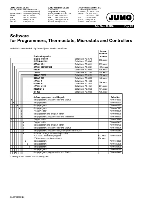
JUMO设备型号说明书
Page 2/2
Accessories for Programmers, Thermostats, Microstats and Controllers
Device designation
DICON 400/500 DICON 401/501
Data Sheet 70.3570 Data Sheet 70.3580
Software programs1 (multilingual)
x
Setup program, program editor and Startup
x
Setup program
x
Setup program
x
Setup program
x
Program editor
x
Setup program and program editor
e-mail:
mail@
Internet:
JUMO Instrument Co. Ltd. JUMO House Temple Bank, Riverway Harlow, Essex CM 20 2TT, UK Phone: +44 1279 635533 Fax: +44 1279 635262 e-mail: sales@ Internet:
eTRON T eTRON M
Data Sheet 70.1050 Data Sheet 70.1060
eTRON M100
Data Sheet 70.1061
iTRON 04 B
Data Sheet 70.2050
mTRON
Data Sheet 70.4010 ... 45
常用模拟开关芯片型号与功能和应用介绍

常用模拟开关芯片型号与功能和应用介绍
1.CD4066:
CD4066是一种四路双开关模拟集成电路。
它可以用作高速CMOS开关、模拟信号开关和数字信号开关。
CD4066具有低电平阈值和高通串脉冲响
应等特性,可以通过外部电压来控制其开关状态。
其应用包括模拟开关、
数据路由、模拟选择器和模拟交换等。
2.MAX4617:
MAX4617是一种低电阻四路双开关。
它具有低电阻和低电平失真的特点,可用于模拟交换、模拟多路复用和模拟电流控制等应用。
MAX4617还
具有高速开关时间和广泛的供电电压范围,适用于多种电路设计。
3.ADG601:
ADG601是一种单路、高精度CMOS模拟开关芯片。
它具有低电位失真、低电流和低电压操作的特点,适用于音频信号开关、电量计选择、过程控
制和自动测试设备等应用。
ADG601还具有低串扰和低抖动等特性,可以
提供高品质的信号传输。
这些模拟开关芯片的功能和应用广泛,可以满足不同领域的需求。
它
们在信号传输、数据交换、功率控制和信号处理等方面发挥着重要作用。
无论是工业自动化、通信设备、消费电子产品还是医疗设备,这些模拟开
关芯片都能够提供可靠和精确的信号控制。
因此,选取适合的模拟开关芯
片对于电路设计和系统性能至关重要。
MAX6355TZUT中文资料
For pricing, delivery, and ordering information, please contact Maxim/Dallas Direct! at 1-888-629-4642, or visit Maxim’s website at .
元器件交易网
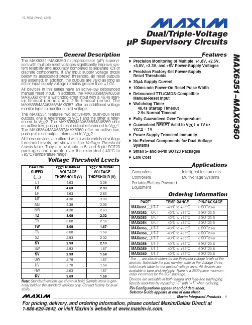
Features
♦ Precision Monitoring of Multiple +1.8V, +2.5V, +3.0V, +3.3V, and +5V Power-Supply Voltages ♦ Precision Factory-Set Power-Supply Reset Thresholds ♦ 20µA Supply Current ♦ 100ms min Power-On Reset Pulse Width ♦ Debounced TTL/CMOS-Compatible Manual-Reset Input ♦ Watchdog Timer 46.4s Startup Timeout 2.9s Normal Timeout ♦ Fully Guaranteed Over Temperature ♦ Guaranteed RESET Valid to VCC1 = 1V or VCC2 = 1V ♦ Power-Supply Transient Immunity ♦ No External Components for Dual-Voltage Systems ♦ Small 5- and 6-Pin SOT23 Packages ♦ Low Cost
Applications
Computers Controllers Portable/Battery-Powered Equipment Intelligent Instruments Multivoltage Systems
6m33d633e200技术参数
6m33d633e200技术参数6m33d633e200是一款先进的技术设备,广泛应用于各个行业。
本文将重点介绍6m33d633e200的技术参数,以便更好地了解和使用该设备。
1. 尺寸与重量:- 6m33d633e200的尺寸为X厘米(长)×Y厘米(宽)×Z厘米(高)。
- 6m33d633e200的重量约为W千克。
2. 处理器:- 6m33d633e200采用先进的处理器技术,具有高性能和低能耗的特点。
- 处理器速度为S GHz,能够快速处理各种任务和数据。
3. 存储容量:- 6m33d633e200拥有大容量的内部存储空间,可用于存储大量数据和文件。
- 内部存储容量为C GB,足够满足日常使用的需求。
4. 内存:- 6m33d633e200配备了高速的内存,能够提供流畅且高效的操作体验。
- 内存容量为M GB,能够支持同时运行多个应用程序和任务。
5. 屏幕:- 6m33d633e200配备了高分辨率的液晶显示屏,能够呈现清晰、鲜艳的图像和视频。
- 屏幕尺寸为P英寸,具有宽广的视野和舒适的观看体验。
6. 摄像头:- 6m33d633e200内置了高像素的摄像头,能够拍摄出高质量的照片和视频。
- 摄像头像素为A万像素,支持自动对焦和光学防抖功能。
7. 电池续航:- 6m33d633e200搭载了容量较大的电池,能够提供长时间的使用时间。
- 电池续航时间约为B小时,可满足一天的正常使用需求。
8. 网络与连接:- 6m33d633e200支持多种网络连接方式,如Wi-Fi、蓝牙等。
- 支持的网络频段为X GHz至Y GHz,确保稳定的网络连接。
9. 操作系统:- 6m33d633e200采用先进的操作系统,提供丰富的功能和良好的用户体验。
- 操作系统版本为Z,具有稳定性和安全性。
10. 其他功能:- 6m33d633e200还具有其他一些特殊功能,如指纹识别、面部识别等,提供更高的安全性和便利性。
MAX541

MAX541是美国MAXIM公司生产的D/A转换芯片,它是低功耗(1.5mW),无缓冲电压输出,能够驱动60kv的负载,用单+5V电源工作的串行16位数模转换器。
其转换时间为1μs,输出电压变换范围为0V~VREF[16]。
下图为芯片的管脚图,并将MAX541的管脚功能列于表3-3中。
表3-3 MAX541管脚功能表
引脚号引脚名称引脚功能
1 OUT DAC 电压输出
2 AGND 模拟地
3 REF 电压参考输入,链接到外接的+2.5V参
考
4 CS 芯片选择,低电平有效
5 SCLK 串行时钟输入
6 DIN 串行数据输入
7 DGND 数字地
8 VDD +5V电源电压
MAX的工作原理是:模拟输出电压VOUT的输出范围由输入不同的数字代码来有规律的控制,当输入的16位数字代码全为0时,输出电压VOUT为0。
当输入的16位数字代码全为1时,输出电压约为VREF即2.5V。
于是VOUT的变化规律是,16位数字代码从0开始,每次加1,一直到全为1,对应的输出电压一直从0开始每次增加VREF*(1/65536)。
1111 1111 1111 1111 VREF*(65535/65536)
…….
…….
1000 0000 0000 0000 VREF*(32768/65536)
…….
……
0000 0000 0000 0001 VREF*(1/65536)
0000 0000 0000 0000 VREF *( 0/65536)。
AD633中文资料

VO = 0.1 V rms
VO = 20 V p-p ∆ VO = 20 V
1
MHz
20
V/µs
2
µs
OUTPUT NOISE
Spectral Density
0.8
Wideband Noise
f = 10 Hz to 5 MHz
1
f = 10 Hz to 10 kHz
90
µV/√Hz mV rms µV rms
–10 V ≤ X, Y ≤ +10 V
SF = 10.00 V Nominal VS = ± 14 V to ± 16 V X = ± 10 V, Y = +10 V Y = ± 10 V, X = +10 V Y Nulled, X = ± 10 V X Nulled, Y = ± 10 V
±1 ±3 ± 0.25% ± 0.01 ± 0.4 ± 0.1 ± 0.3 ± 0.1 ±5
The AD633 is available in an 8-lead plastic DIP package (N) and 8-lead SOIC (R). It is specified to operate over the 0°C to +70°C commercial temperature range (J Grade) or the –40°C to +85°C industrial temperature range (A Grade).
Specifications subject to change without notice.
ABSOLUTE MAXIMUM RATINGS1
Supply Voltage . . . . . . . . . . . . . . . . . . . . . . . . . . . . . . . . . ± 18 V Internal Power Dissipation2 . . . . . . . . . . . . . . . . . . . . 500 mW Input Voltages3 . . . . . . . . . . . . . . . . . . . . . . . . . . . . . . . . ± 18 V Output Short Circuit Duration . . . . . . . . . . . . . . . . . Indefinite
ap6335芯片手册
ap6335芯片手册
(原创版)
目录
1.AP6335 芯片概述
2.AP6335 芯片的功能特点
3.AP6335 芯片的技术参数
4.AP6335 芯片的应用领域
5.AP6335 芯片的发展前景
正文
AP6335 芯片是由我国某知名半导体公司研发的一款高性能、低功耗的芯片。
该芯片以其卓越的性能和稳定的可靠性在市场上备受欢迎,被广泛应用于各种电子设备中。
AP6335 芯片的功能特点主要表现在以下几个方面:首先,它具有高效的数据处理能力,能够快速、准确地处理各种数据,大大提高了设备的运行效率。
其次,它具有强大的抗干扰能力,能够在复杂的电磁环境中稳定工作,确保设备的正常运行。
再次,它具有低功耗的特点,能够在保证设备性能的同时,降低设备的能耗,延长设备的使用寿命。
在技术参数方面,AP6335 芯片的工作电压范围为 1.8V-3.6V,工作温度范围为 -40℃至 85℃,具有优异的稳定性和可靠性。
其最大输入输出电流分别为150mA 和 50mA,能够满足大部分设备的需求。
AP6335 芯片的应用领域非常广泛,可以应用于智能家居、工业控制、医疗设备、消费电子等各个领域。
例如,在家居领域,AP6335 芯片可以用于智能灯泡、智能插座等设备的制造;在工业控制领域,AP6335 芯片可以用于传感器、控制器等设备的制造;在医疗设备领域,AP6335 芯片可以用于心电图仪、血压计等设备的制造。
随着科技的不断发展,AP6335 芯片的发展前景非常广阔。
在未来,它将继续提升自身的性能,以满足更多领域的需求。
同时,它也将不断降低自身的成本,以提高自身的竞争力。
第1页共1页。
MAX6336US16D3-T中文资料
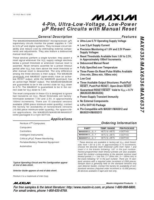
For free samples & the latest literature: , or phone 1-800-998-8800.For small orders, phone 1-800-835-8769.General DescriptionThe MAX6335/MAX6336/MAX6337 microprocessor (µP)supervisory circuits monitor the power supplies in 1.8V to 3.3V µP and digital systems. They increase circuit reli-ability and reduce cost by eliminating external compo-nents and adjustments. They also feature a debounced manual-reset input.These devices perform a single function: they assert a reset signal whenever the V CC supply voltage declines below a preset threshold or whenever manual reset is asserted. Reset remains asserted for a preset timeout period after V CC has risen above the reset threshold or after manual reset is deasserted. The only difference among the three devices is their output. The MAX6336(push/pull) and MAX6337 (open-drain) have an active-low RESET output, while the MAX6335 (push/pull) has an active-high RESET output. The MAX6335/MAX6336are guaranteed to be in the correct state for V CC down to 0.7V. The MAX6337 is guaranteed to be in the cor-rect state for V CC down to 1.0V.The reset comparator in these ICs is designed to ignore fast transients on V CC . Reset thresholds are factory-trimmable between 1.6V and 2.5V, in approximately 100mV increments. There are 15 standard versions available (2500 piece minimum-order quantity); contact the factory for availability of nonstandard versions (10,000 piece minimum-order quantity). For space-criti-cal applications, the MAX6335/MAX6336/MAX6337come packaged in a 4-pin SOT143.ApplicationsPentium II™ Computers Computers ControllersIntelligent InstrumentsCritical µP/µC Power Monitoring Portable/Battery-Powered Equipment AutomotiveFeatureso Ultra-Low 0.7V Operating Supply Voltageo Low 3.3µA Supply Currento Precision Monitoring of 1.8V and 2.5V Power-Supply Voltages o Reset Thresholds Available from 1.6V to 2.5V,in Approximately 100mV Increments o Debounced Manual Reset o Fully Specified over Temperatureo Three Power-On Reset Pulse Widths Available (1ms min, 20ms min, 100ms min)o Low Costo Three Available Output Structures: Push/Pull RESET , Push/Pull RESET, Open-Drain RESET o Guaranteed RESET/RESET Valid to V CC = 0.7V (MAX6335/MAX6336)o Power-Supply Transient Immunity o No External Components o 4-Pin SOT143 Packageo Pin-Compatible with MAX811/MAX812 and MAX6314/MAX6315MAX6335/MAX6336/MAX63374-Pin, Ultra-Low-Voltage, Low-Power µP Reset Circuits with Manual Reset________________________________________________________________Maxim Integrated Products 119-1412; Rev 0; 12/98Ordering Information* These devices are available in factory-set V CC reset thresh-olds from 1.6V to 2.5V, in approximately 0.1V increments.Choose the desired reset threshold suffix from Table 1 and insert it in the blanks following “US” in the part number.Factory-programmed reset timeout periods are also available.Insert the number corresponding to the desired nominal reset timeout period (1 = 1ms min, 2 = 20ms min, 3 = 100ms min) in the blank following “D” in the part number. There are 15 stan-dard versions with a required order increment of 2500 pieces.Sample stock is generally held on the standard versions only (see Selector Guide). Contact the factory for availability of non-standard versions (required order increment is 10,000 pieces).All devices available in tape-and-reel only.Typical Operating Circuit and Pin Configuration appear at end of data sheet.Selector Guide appears at end of data sheet.Pentium II is a trademark of Intel Corp.M A X 6335/M A X 6336/M A X 63374-Pin, Ultra-Low-Voltage, Low-Power µP Reset Circuits with Manual Reset 2_______________________________________________________________________________________ABSOLUTE MAXIMUM RATINGSELECTRICAL CHARACTERISTICS(V CC = full range, MR = V CC or unconnected, T A = -40°C to +85°C, unless otherwise noted. Typical values are at T A = +25°C and V CC = 3V, reset not asserted.)Stresses beyond those listed under “Absolute Maximum Ratings” may cause permanent damage to the device. These are stress ratings only, and functional operation of the device at these or any other conditions beyond those indicated in the operational sections of the specifications is not implied. Exposure to absolute maximum rating conditions for extended periods may affect device reliability.Terminal Voltage (with respect to GND)V CC ......................................................................-0.3V to +6V Push/Pull RESET or RESET , MR ............-0.3V to (V CC + 0.3V)Open-Drain RESET ..............................................-0.3V to +6V Input Current (V CC ).............................................................20mA Output Current (RESET, RESET ).........................................20mA Rate of Rise, V CC ............................................................100V/µsContinuous Power Dissipation (T A = +70°C)SOT143 (derate 4mW/°C above +70°C).....................320mW Operating Temperature Range ...........................-40°C to +85°C Storage Temperature Range.............................-65°C to +160°C Lead Temperature (soldering, 10sec).............................+300°C4-Pin, Ultra-Low-Voltage, Low-Power µP Reset Circuits with Manual Reset_______________________________________________________________________________________32.02.62.23.03.63.83.43.24.0-602.4-40-202.820406080100SUPPLY CURRENT vs. TEMPERATURETEMPERATURE (°C)I C C (µA )0.9500.9900.9701.0001.0301.0401.0201.0101.050-60-400.980-200.96020406080100NORMALIZED RESET TIMEOUT PERIODvs. TEMPERATURETEMPERATURE (°C)N O R M A L I Z E D R E S E T T I M E O U T P E R I O D 020103060705040800.501.001.502.002.503.00OUTPUT VOLTAGE LOW vs. SUPPLY VOLTAGEV CC (V)O U T P U T V O L T A G E L O W (m V )402080601001201401600.5 1.0 1.250.75 1.5 1.75 2.0 2.25 2.5OUTPUT VOLTAGE HIGH vs. SUPPLY VOLTAGEV CC (V)O U T P U T V O L T A G E H I G H (V C C - V O H ) (m V )100100001002004003005006000.1110MAXIMUM TRANSIENT DURATION vs. RESET COMPARATOR OVERDRIVERESET COMPARATOR OVERDRIVE (mV)M A X I M U M T R A N S I E N T D U RA T I O N (µs )1020-20403070605080-600-4020406080100V CC FALLING PROPAGATION DELAYvs. TEMPERATURETEMPERATURE (°C)P R O P A G A T I O N D E L A Y (µs )__________________________________________Typical Operating Characteristics(Reset not asserted, T A = +25°C, unless otherwise noted.)MAX6335/MAX6336/MAX6337M A X 6335/M A X 6336/M A X 63374-Pin, Ultra-Low-Voltage, Low-Power µP Reset Circuits with Manual Reset 4_______________________________________________________________________________________Pin DescriptionApplications InformationManual-Reset InputsMany µP-based products require manual-reset capabil-ity, allowing the operator, a test technician, or external logic circuitry to initiate a reset. A logic low on MR asserts reset. Reset remains asserted while MR is low,and for the reset active timeout period after MR returns high. MR has an internal 20k Ωpull-up resistor, so it can be left unconnected if not used. Connect a normally open momentary switch from MR to GND to create a manual-reset function; external debounce circuitry is not required.Interfacing to µPs with Bidirectional Reset PinsSince the RESET output on the MAX6337 is open-drain,this device interfaces easily with µPs that have bidirec-tional reset pins, such as the Motorola 68HC11.Connecting the µP supervisor’s RESET output directly to the microcontroller’s (µC’s) RESET pin with a single pull-up resistor allows either device to assert reset (Figure 1).Negative-Going V CC TransientsIn addition to issuing a reset to the µP during power-up,power-down, and brownout conditions, these devices are relatively immune to short-duration, negative-going V CC transients (glitches). The Typical Operating Characteristics show the Maximum Transient Duration vs. Reset Comparator Overdrive graph. The graph shows the maximum pulse width that a negative-going V CC transient may typically have without issuing a resetsignal. As the amplitude of the transient increases, the maximum allowable pulse width decreases.Ensuring a Valid Reset Outputdown to V CC = 0When V CC falls below 1V and approaches the minimum operating voltage of 0.7V, push/pull-structured reset sinking (or sourcing) capabilities decrease drastically.High-impedance CMOS-logic inputs connected to the RESET pin can drift to indeterminate voltages. This does not present a problem in most cases, since most µPs and circuitry do not operate at V CC below 1V. For the MAX6336, where RESET must be valid down to 0,adding a pull-down resistor between RESET and GND removes stray leakage currents, holding RESET lowFigure 1. Interfacing to µPs with Bidirectional Reset Pins4-Pin, Ultra-Low-Voltage, Low-Power µP Reset Circuits with Manual Reset_______________________________________________________________________________________5MAX6335/MAX6336/MAX6337*100mV increments, with a ±1.8% room-temperature variance.Table 1. Factory-Trimmed Reset Thresholds*Figure 2. Ensuring Reset Valid down to V CC = 0(Figure 2a). The pull-down resistor value is not critical;100k Ωis large enough not to load RESET , and small enough to pull it low. For the MAX6335, where RESET must be valid to V CC = 0, a 100k Ωpull-up resistor between RESET and V CC will hold RESET high when V CC falls below 0.7V (Figure 2b).Since the MAX6337 has an open-drain, active-low out-put, it typically uses a pull-up resistor. With this device,RESET will most likely not maintain an active condition,but will drift to a non-active level due to the pull-up resistor and the reduced sinking capability of the open-drain device. Therefore, this device is not recommend-ed for applications where the RESET pin is required to be valid down to V CC = 0.M A X 6335/M A X 6336/M A X 63374-Pin, Ultra-Low-Voltage, Low-Power µP Reset Circuits with Manual Reset 6_______________________________________________________________________________________PARTOUTPUT STAGE NOMINAL V TH (V)MINIMUM RESET TIMEOUT (ms)SOT TOP MARKMAX6335US23D3-T Push/Pull RESET 2.30100KABQ MAX6335US22D3-T Push/Pull RESET 2.20100KAAR MAX6335US20D3-T Push/Pull RESET 2.00100KABP MAX6335US18D3-T Push/Pull RESET 1.80100KAAQ MAX6335US16D3-T Push/Pull RESET 1.60100KAAP MAX6336US23D3-T Push/PullRESET 2.30100KAAW MAX6336US22D3-T Push/Pull RESET 2.20100KAAV MAX6336US20D3-T Push/Pull RESET 2.00100KAAU MAX6336US18D3-T Push/Pull RESET 1.80100KAAT MAX6336US16D3-T Push/Pull RESET 1.60100KAAS MAX6337US23D3-T Open-Drain RESET 2.30100KABS MAX6337US22D3-T Open-Drain RESET 2.20100KAAZ MAX6337US20D3-T Open-Drain RESET 2.00100KABRMAX6337US18D3-T Open-Drain RESET 1.80100KAAY MAX6337US16D3-TOpen-Drain RESET1.60100KAAXSelector Guide (standard versions *)Pin ConfigurationTypical Operating Circuit* Sample stock is generally held on all standard versions.MAX6335/MAX6336/MAX63374-Pin, Ultra-Low-Voltage, Low-Power µP Reset Circuits with Manual Reset_______________________________________________________________________________________7TRANSISTOR COUNT:505Chip InformationPackage InformationM A X 6335/M A X 6336/M A X 63374-Pin, Ultra-Low-Voltage, Low-Power µP Reset Circuits with Manual Reset Maxim cannot assume responsibility for use of any circuitry other than circuitry entirely embodied in a Maxim product. No circuit patent licenses are implied. Maxim reserves the right to change the circuitry and specifications without notice at any time.8_____________________Maxim Integrated Products, 120 San Gabriel Drive, Sunnyvale, CA 94086 408-737-7600©1998 Maxim Integrated ProductsPrinted USAis a registered trademark of Maxim Integrated Products.NOTES。
ap6335芯片手册

ap6335芯片手册【实用版】目录1.AP6335 芯片概述2.AP6335 芯片的主要特性3.AP6335 芯片的应用领域4.AP6335 芯片的技术参数5.AP6335 芯片的封装与引脚说明6.AP6335 芯片的使用建议正文AP6335 是一款高性能、低功耗的芯片,适用于各种电子设备和系统。
它具有许多优秀的特性,如高可靠性、宽工作电压范围、强大的抗干扰能力等,使其在各种应用中都能表现优秀。
AP6335 的主要特性包括:- 高可靠性:该芯片采用了特殊的设计,确保了在各种环境下都能保持稳定的工作性能。
- 宽工作电压范围:AP6335 的工作电压范围广泛,可以从 1.8V 到5.5V,这使得它适用于各种电池供电的设备。
- 强大的抗干扰能力:AP6335 具有优秀的抗电磁干扰和抗静电干扰能力,确保了设备的稳定运行。
AP6335 芯片的应用领域非常广泛,包括但不限于以下几个领域:- 消费电子:如手机、平板电脑、电视等。
- 工业控制:如工控机、可编程逻辑控制器(PLC)等。
- 医疗设备:如心电图仪、超声波设备等。
AP6335 芯片的技术参数如下:- 工作电压:1.8V 至 5.5V- 工作温度:-40℃至 85℃- 储存温度:-65℃至 125℃- 封装形式:SOP、DIP 等- 引脚数量:多种规格,最多可达 100 脚AP6335 芯片的封装与引脚说明如下:- 封装形式:SOP、DIP 等- 引脚数量:多种规格,最多可达 100 脚- 引脚排列:符合 JEDEC 标准,易于焊接和加工使用 AP6335 芯片时,建议注意以下几点:- 在使用前,请详细阅读芯片手册,了解其特性和使用方法。
- 在设计和焊接时,请确保符合相关标准,避免因为操作不当导致的损坏。
- 在使用过程中,应确保工作电压、工作温度等都在允许范围内,以保证设备的稳定性和寿命。
max531中文资料
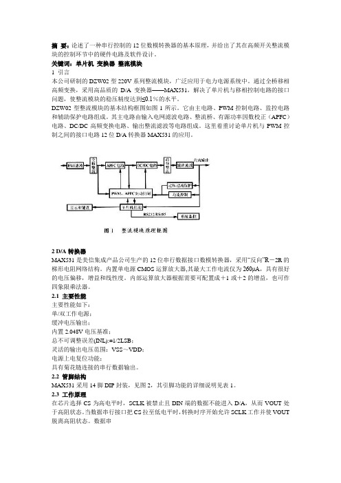
摘要:论述了一种串行控制的12位数模转换器的基本原理,并给出了其在高频开关整流模块的控制环节中的硬件电路及软件设计。
关键词:单片机变换器整流模块1 引言本公司研制的DZW02型220V系列整流模块,广泛应用于电力电源系统中。
通过全桥移相高频变换,采用高品质的D/A变换器——MAX531,解决了单片机与移相控制电路的接口问题,使整流模块的稳压精度达到≤0.1%的水平。
DZW02型整流模块的基本结构框图如图1所示。
它由主电路、PWM控制电路、监控电路和辅助保护电路组成。
其主电路由输入电网滤波电路、整流桥、有源功率因数校正(APFC)电路、DC/DC高频变换电路、输出整流滤波等电路组成。
这里着重讨论单片机与PWM控制之间的接口电路12位D/A转换器MAX531的应用。
2 D/A转换器MAX531是美信集成产品公司生产的12位串行数据接口数模转换器,采用“反向”R-2R的梯形电阻网络结构。
内置单电源CMOS运算放大器,其最大工作电流仅为260μA,具有很好的电压偏移,增益和线性度。
内部运算放大器根据需要可配置成+1或+2的增益,也可作四象限乘法器。
2.1 主要性能主要性能如下:单/双工作电源;缓冲电压输出;内置2.048V电压基准;总不可调整误差(INL):±1/2LSB;灵活的输出电压范围:VSS~VDD;电源上电复位功能;具有菊花链连接的串行数据输出。
2.2 管脚结构MAX531采用14脚DIP封装,见图2,其引脚功能的详细说明见表1。
2.3 工作原理在芯片选择CS为高电平时,SCLK被禁止且DIN端的数据不能进入D/A,从而VOUT处于高阻状态。
当数据串行接口把CS拉至低电平时,转换时序开始允许SCLK工作并使VOUT 脱离高阻状态。
数据串行接口将SCLK时钟序列传给SCLK,在SCLK的上升沿,16位串行数字输到DIN被锁入12位移位寄存器,其中高4位(MSB)移入DOUT寄存器,此时D/A以菊花链连接才能用到。
MAX706中文简介
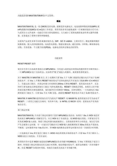
功能监控器MAX705/706/813中文资料。
概述MAX705/706/813L是一组CMOS监控电路,能够监控电源电压、电池故障和微处理器(MPU或mP)或微控制器(MCU或mC)的工作状态。
将常用的多项功能集成到一片8脚封装的小芯片内,与采用分立元件或单一功能芯片组合的电路相比,大大减小了系统电路的复杂性和元器件的数量,显著提高了系统可靠性和精确度。
该系列产品采用3种不同的8脚封装形式:DIP、SO和mMAX。
主要应用于:微处理器和微控制器系统;嵌入式控制器系统;电池供电系统;智能仪器仪表;通信系统;寻呼机;蜂窝移动电话机;手持设备;个人数字助理(PDA);电脑电话机和无绳电话机等等。
功能说明RESET/RESET操作复位信号用于启动或者重新启动MPU/MCU,令其进入或者返回到预知的循环程序并顺序执行。
一旦MPU/MCU处于未知状态,比如程序“跑飞”或进入死循环,就需要将系统复位。
对于MAX705和MAX706而言,在上电期间只要Vcc大于1.0V,就能保证输出电压不高于0.4V 的低电平。
在Vcc上升期间RESET维持低电平直到电源电压升至复位门限(4.65V或4.40V)以上。
在超过此门限后,内部定时器大约再维持200ms后释放RESET,使其返回高电平。
无论何时只要电源电压降低到复位门限以下(即电源跌落),RESET引脚就会变低。
如果在已经开始的复位脉冲期间出现电源跌落,复位脉冲至少再维持140ms。
在掉电期间,一旦电源电压Vcc 降到复位门限以下,只要Vcc不比1.0V还低,就能使RESET维持电压不高于0.4V的低电平。
MAX705和MAX706提供的复位信号为低电平RESET,而MAX813L提供的复位信号为高电平RESET,三者其它功能完全相同。
有些单片机,如INTEL的80C51系列,需要高电平有效的复位信号。
看门狗定时器MAX705/706/813L片内看门狗定时器用于监控MPU/MCU的活动。
ap6335芯片手册

ap6335芯片手册
(原创版)
目录
1.AP6335 芯片概述
2.AP6335 芯片的主要特性
3.AP6335 芯片的内部结构
4.AP6335 芯片的引脚功能
5.AP6335 芯片的工作原理
6.AP6335 芯片的应用领域
7.AP6335 芯片的竞争对手
正文
AP6335 芯片是由我国某知名半导体公司研发的一款高性能、低功耗的芯片。
该芯片凭借其出色的性能和稳定性,在我国市场上备受欢迎。
AP6335 芯片的主要特性包括高性能、低功耗、高可靠性等。
这些特性使得该芯片在各种应用场景中都能发挥出良好的性能。
AP6335 芯片的内部结构精细,采用了先进的设计理念和技术。
其内部集成了 CPU、GPU、RAM 等多个功能单元,可以满足不同应用场景的需求。
AP6335 芯片的引脚功能明确,每个引脚都有其特定的功能。
引脚的合理连接和使用,可以保证芯片的正常工作和稳定运行。
AP6335 芯片的工作原理是通过内部的 CPU 和 GPU 进行数据处理和图形渲染,RAM 则负责存储数据和程序。
在实际应用中,该芯片可以进行各种复杂的数据处理和图形渲染任务。
AP6335 芯片的应用领域广泛,可以应用于手机、平板、电视等各类
电子产品中。
其出色的性能和稳定性,使得这些电子产品可以提供更好的用户体验。
在市场上,AP6335 芯片的竞争对手主要包括国际上的一些知名半导体公司。
虽然面临竞争,但 AP6335 芯片凭借其出色的性能和稳定性,在我国市场上仍占有一席之地。
T6335A-350AWG中文资料
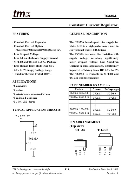
TECH tmT6335AConstant Current RegulatorFEATURES• Constant Current Regulator • Constant Current Option :150/210/225/240/260/280/300/320/350 mA • Low Dropout Voltage• Low 0.1 uA Shutdown Supply Current • SOT-89 and TO-252 lead-free Package • ESD Human Body Mode Over 5KV • 2.7V to 5V Supply Voltage Range • Build in Thermal Protect 160 °CAPPLICATIONS• Flash Light • Lighting• Portable Communication Devices • Handheld Electronics • DC/DC LED driverTYPICAL APPLICATION CIRCUITSV IN GENERAL DESCRIPTIONThe T6335A low-dropout bias supply for white LED is a high-performance used in conventional white LED designs.The T6335A has lower bias variation with supply voltage variation, significantly lower dropout voltage Low Shutdown Current in some applications, significantly improved efficiency from DC 2.7V to 5V. The T6335A is available in SOT-89 and TO-252 lead-free package.PART NUMBER EXAMPLESPIN ARRANGEMENT (Top view)SOT-89 TO-252G N DV D DO U TG N DV D DO U TPart no.Current Package type T6335A-350AXG 350mA SOT-89 T6335A-350AWG350mA TO-252T6335A-150AXG150mA SOT-89 T6335A-150AWG 150mA TO-252PIN DESCRIPTIONSYMBOL Pin no.DESCRIPTIONOUT 1 LED Cathode Connection. VSS 2 Ground VDD 3 Power supplyABSOLUTE MAXIMUM RATINGSParameterSymbol Value Unit Voltage on any pin relative to GND V IN -0.3 to 6 V Operating Temperature RangT A -40 to +85 °C Maximum Soldering Temperature (at leads, 10 sec) T LEAD 300 °CStorage Temperature RangT S-65 to +150°CContinuous Power Dissipation ( T A = +70°C )1 WElectrical Characteristics(Typical values are at TA =25°C)Symbol Description Conditions Min. Typ. Max UnitV DDOperating voltage rangeVDD is power supply input2.75VT6335A-350 329 350 371 mA T6335A-320 300 320 339 mAT6335A-300 282 300 318 mAT6335A-280 263 280 296 mA T6335A-260 244 260 275 mA T6335A-240 225 240 254 mA T6335A-225 211 225 238 mA T6335A-210 197 210 222 mA I LEDMaximum LED sink currentVDD = 4.5V VLED =3.5VT6335A-150 141 150 159 mAT TP Thermat Protect 160 °C I LSDLED leakage current in shutdown VDD = GND, VLED = 5V0.2 1 uATypical Operating CharacteristicsTest CircuitVDD VS. Iout CurvePACKAGE DIMENSIONS SOT-89TO-252Dimension in mm SymbolMin. Max.A 1.40 1.60B 0.44 0.56B1 0.36 0.48C 0.35 0.44D 4.40 4.60D1 1.35 1.83E 2.29 2.60H 3.94 4.25e 1.50BSC e1 3.00BSC L 0.89 1.2Dimension in inchSymbolMin. Max.A 0.086 0.094A1 0.040 0.050b 0.024TYP.b2 0.205 0.215c 0.018 0.023c1 0.018 0.023D 0.210 0.220E 0.250 0.265D1 0.180 -E1 0.150 -e 0.090BSC.e1 0.180BSC.H 0.370 0.410L 0.020 -L1 0.025 0.040L2 0.060 0.080。
32通道16位DA转换器MAX5631的原理及应用
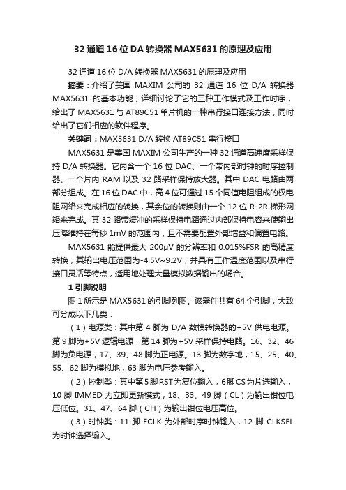
32通道16位DA转换器MAX5631的原理及应用32通道16位D/A转换器MAX5631的原理及应用摘要:介绍了美国MAXIM公司的32通道16位D/A转换器MAX5631的基本功能,详细讨论了它的三种工作模式及工作时序,给出了MAX5631与AT89C51单片机的一种串行接口连接方法,同时给出了它们相应的软件程序。
关键词:MAX5631 D/A转换AT89C51 串行接口MAX5631是美国MAXIM公司生产的一种32通道高速度采样保持D/A转换器。
它内含一个16位DAC、一个带内部时钟的时序控制器、一个片内RAM以及32路采样保持放大器。
其中DAC电路由两部分组成。
在16位DAC中,高4位可通过15个同值电阻组成的权电阻网络来完成相应的转换,其余位的转换则由一个12位R-2R梯形网络来完成。
其32路带缓冲的采样保持电路通过内部保持电容来使输出压降维持在每秒1mV的范围内,且不需要配置外部增益和偏置电路。
MAX5631能提供最大200μV的分辨率和0.015%FSR的高精度转换,其输出电压范围为-4.5V~9.2V,并具有工作温度范围以及串行接口灵活等特点,适用地处理大量模拟数据输出的场合。
1 引脚说明图1所示是MAX5631的引脚列图。
该器件共有64个引脚,大致可分成以下几类:(1)电源类:其中第4脚为D/A数模转换器的+5V供电电源。
第9脚为+5V逻辑电源,第14脚为+5V采样保持电路。
16、32、46脚为负电源,17、39、48脚为正电源。
13脚为数字地,15、25、40、55、62脚为模拟地,63脚为电压参考输入。
(2)控制类:其中第5脚RST为复位输入,6脚CS为片选输入,10脚IMMED为立即更新模式,18、33、49脚(CL)为输出钳位电压低位。
31、47、64脚(CH)为输出钳位电压高位。
(3)时钟类:11脚ECLK为外部时序时钟输入,12脚CLKSEL 为时钟选择输入。
(4)串行接口类:7脚DIN为串行数据输入,8脚SCLK为串行时钟输入。
ap6335芯片手册
ap6335芯片手册(原创版)目录1.AP6335 芯片概述2.AP6335 芯片的功能特点3.AP6335 芯片的应用领域4.AP6335 芯片的技术参数5.AP6335 芯片的开发与应用支持正文AP6335 芯片是一款高性能、低功耗的系统级芯片 (SoC),由业内领先的半导体制造商设计推出。
该芯片采用了先进的制程工艺,具备高性能、低功耗、小尺寸等特点,可广泛应用于智能手机、平板电脑、物联网等终端设备中。
AP6335 芯片在设计上注重功能性与灵活性,具备丰富的功能特点。
其中包括:1.高性能:AP6335 芯片采用了四核 ARM Cortex-A72 处理器,主频高达2.0GHz,可提供高效的计算性能。
2.低功耗:AP6335 芯片采用了 28nm 制程工艺,并采用了动态功耗管理技术,可实现低功耗运行。
3.强大的图形处理能力:AP6335 芯片内置了高性能的 Mali-T880 GPU,可提供出色的图形处理能力,支持高清视频播放和游戏流畅运行。
4.多样化的接口和扩展能力:AP6335 芯片支持多种接口和扩展能力,包括 USB、HDMI、PCIe、SATA 等,可满足不同设备的需求。
5.安全性:AP6335 芯片内置了硬件加密加速器和安全子系统,可提供安全可靠的运行环境。
AP6335 芯片可应用于多个领域,包括智能手机、平板电脑、物联网、工业控制等。
在智能手机和平板电脑领域,AP6335 芯片可提供高性能、低功耗的计算和图形处理能力,支持高清显示和流畅运行。
在物联网和工业控制领域,AP6335 芯片可提供可靠的计算和通信能力,支持设备的智能化和联网化。
AP6335 芯片的技术参数包括主频、CPU 核心、GPU 型号、内存容量、存储容量、接口和扩展能力等。
在开发与应用支持方面,AP6335 芯片提供了完整的开发板和软件开发工具包 (SDK),可帮助开发者快速进行产品开发和测试。
同时,AP6335 芯片也支持多种操作系统,包括 Android、Linux、FreeRTOS 等,可满足不同应用场景的需求。
FAIRCHILD FDG6331L Integrated Load Switch 数据手册
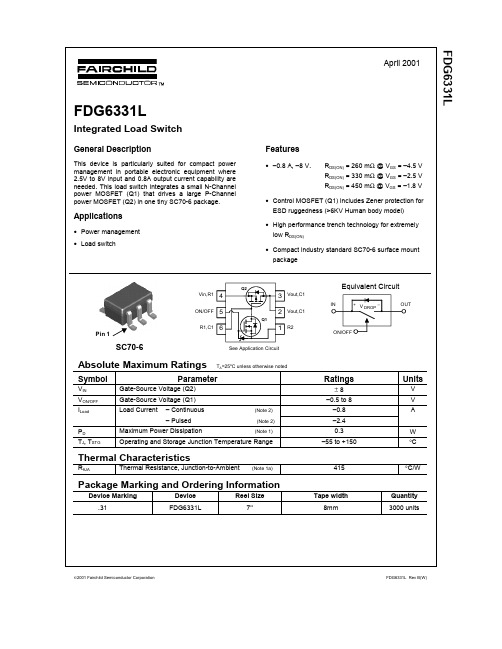
FDG6331L Pin 12001 Fairchild Semiconductor Corporation FDG6331L Rev B(W)TRADEMARKSThe following are registered and unregistered trademarks Fairchild Semiconductor owns or is authorized to use and is not intended to be an exhaustive list of all such trademarks.LIFE SUPPORT POLICYFAIRCHILD’S PRODUCTS ARE NOT AUTHORIZED FOR USE AS CRITICAL COMPONENTS IN LIFE SUPPORTDEVICES OR SYSTEMS WITHOUT THE EXPRESS WRITTEN APPROVAL OF FAIRCHILD SEMICONDUCTOR CORPORATION.As used herein:1. Life support devices or systems are devices or systems which, (a) are intended for surgical implant intothe body, or (b) support or sustain life, or (c) whosefailure to perform when properly used in accordancewith instructions for use provided in the labeling, can be reasonably expected to result in significant injury to the user.2. A critical component is any component of a lifesupport device or system whose failure to perform can be reasonably expected to cause the failure of the life support device or system, or to affect its safety or effectiveness.PRODUCT STATUS DEFINITIONS Definition of Terms Datasheet Identification Product Status DefinitionAdvance InformationPreliminary No Identification Needed Obsolete This datasheet contains the design specifications for product development. Specifications may change in any manner without notice.This datasheet contains preliminary data, andsupplementary data will be published at a later date.Fairchild Semiconductor reserves the right to make changes at any time without notice in order to improve design.This datasheet contains final specifications. Fairchild Semiconductor reserves the right to make changes at any time without notice in order to improve design.This datasheet contains specifications on a product that has been discontinued by Fairchild semiconductor.The datasheet is printed for reference information only.Formative or In DesignFirst ProductionFull ProductionNot In ProductionDISCLAIMERFAIRCHILD SEMICONDUCTOR RESERVES THE RIGHT TO MAKE CHANGES WITHOUT FURTHER NOTICE TO ANY PRODUCTS HEREIN TO IMPROVE RELIABILITY , FUNCTION OR DESIGN. FAIRCHILD DOES NOT ASSUME ANY LIABILITY ARISING OUT OF THE APPLICATION OR USE OF ANY PRODUCT OR CIRCUIT DESCRIBED HEREIN; NEITHER DOES IT CONVEY ANY LICENSE UNDER ITS PATENT RIGHTS, NOR THE RIGHTS OF OTHERS.PACMAN™POP™PowerTrench QFET™QS™QT Optoelectronics™Quiet Series™SILENT SWITCHER SMART START™Star* Power™Stealth™FAST FASTr™GlobalOptoisolator™GTO™HiSeC™ISOPLANAR™LittleFET™MicroFET™MICROWIRE™OPTOLOGIC™OPTOPLANAR™Rev. H1ACEx™Bottomless™CoolFET™CROSSVOLT ™DenseTrench™DOME™EcoSPARK™E 2CMOS TM EnSigna TM FACT™FACT Quiet Series™SuperSOT™-3SuperSOT™-6SuperSOT™-8SyncFET™TinyLogic™UHC™UltraFET VCX™。
6m33d633e200技术参数
6m33d633e200技术参数
6m33d633e200是一款技术先进的设备,它具有多项令人惊叹的特点和功能。
首先,它采用了最新的6m33d633e200技术,能够实现高效的数据处理和传输。
这种技术使得设备的性能得到了极大的提升,同时也保证了数据的安全性和可靠性。
6m33d633e200具有出色的耐用性和稳定性。
它采用了高质量的材料和先进的制造工艺,从而确保了设备的长期使用。
无论是在恶劣的环境下还是在高强度的工作条件下,6m33d633e200都能保持良好的运行状态,不会出现故障或损坏。
6m33d633e200还具有出色的适应性和灵活性。
它可以根据不同的需求和应用场景进行定制和调整,以满足用户的特定需求。
无论是在工业生产中还是在科学研究中,6m33d633e200都能发挥出色的作用,为用户提供高效便捷的解决方案。
除此之外,6m33d633e200还具有简单易用的特点。
它采用了友好的用户界面和智能化的操作系统,使得用户无需复杂的操作就能够轻松使用设备。
即使是对于非专业人士来说,也能够迅速上手并享受到6m33d633e200带来的便利和效益。
总的来说,6m33d633e200是一款值得信赖的高性能设备。
它的先进技术、耐用稳定性、适应性灵活性以及简单易用性使得它在各个领域都有着广阔的应用前景。
无论是在工业制造、科学研究还是其他
领域,6m33d633e200都能够为用户提供卓越的表现和高效的解决方案。
相信在不久的将来,6m33d633e200将会成为行业的领先者,为人类的进步和发展做出重要贡献。
MAXIM的MAX31865温度检测器解决方案
MAXIM的MAX31865温度检测器解决方案简介MAXIM的MAX31865温度检测器是一款高精度、数字温度传感器。
它采用RTD传感器进行温度测量,支持多种RTD类型,如PT100和PT1000。
MAX31865还具有内置的线性化和数据过滤功能,可实现高精度温度测量和抗干扰能力。
MAX31865的主要特点•采用RTD传感器进行温度测量•支持多种RTD类型,如PT100和PT1000•内置线性化和数据过滤功能•支持SPI接口,通信速度高达10MHz•工作电压范围广泛,从3.0V到5.5V•支持低功耗模式,适用于移动、便携式应用MAX31865的应用领域MAX31865温度检测器广泛应用于以下领域: - 工业自动化 - 能源管理 - 环境监测 - 医疗设备 - 汽车电子MAX31865的电路设计原理MAX31865的电路设计包括三个主要部分:RTD传感器、MAX31865芯片和微控制器。
其中,RTD传感器负责温度测量,MAX31865芯片负责数据采集和处理,微控制器负责数据显示和传输。
以下是MAX31865电路设计的基本原理图:RTD传感器 MAX31865芯片微控制器| | |+---------------+----------------+|总线在这个电路中,RTD传感器连接到MAX31865芯片的输入引脚。
MAX31865芯片对传感器信号进行放大、滤波和线性化处理,然后将其转换为数字信号,并通过SPI总线发送给微控制器。
微控制器将接收到的数字信号转换为温度值,并在显示屏上显示。
MAX31865的注意事项在使用MAX31865温度检测器时,需要注意以下几点:•要正确选择RTD传感器的类型和额定阻值•要正确设置MAX31865芯片的配置寄存器,以实现期望的温度测量精度和抗干扰能力•要正确连接MAX31865芯片和微控制器的SPI总线,并配置正确的通信参数•要避免将MAX31865芯片的引脚连接到错误的电压或环境下,以避免损坏芯片或影响测量精度结论MAXIM的MAX31865温度检测器是一款高精度、数字温度传感器,适用于工业自动化、能源管理、环境监测、医疗设备和汽车电子等领域。
Sennheiser D1 Vocal Set 系列产品说明说明书
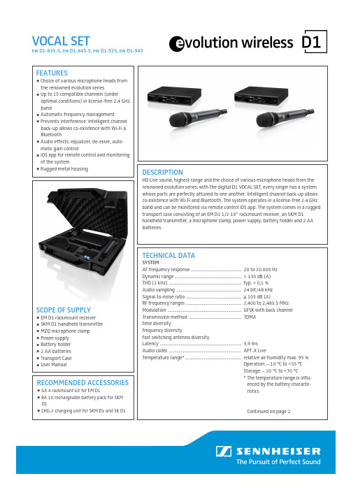
FEATURESChoice of various microphone heads from the renowned evolution seriesUp to 15 compatible channels (underoptimal conditions) in license-free 2.4 GHz bandAutomatic frequency managementPrevents interference: Intelligent channel back-up allows co-existence with Wi-Fi & BluetoothAudio effects: equalizer, de-esser, auto-matic gain controliOS app for remote control and monitoring of the systemRugged metal housingDESCRIPTIONHD Live sound, highest range and the choice of various microphone heads from the renowned evolution series: with the digital D1 VOCAL SET, every singer has a system whose parts are perfectly attuned to one another. Intelligent channel back-up allows co-existence with Wi-Fi and Bluetooth. The system operates in a license-free 2.4 GHz band and can be monitored via remote control iOS app. The system comes in a rugged transport case consisting of an EM D1 1/2 19“ rackmount receiver, an SKM D1 handheld transmitter, a microphone clamp, power supply, battery holder and 2 AA batteries.TECHNICAL DATASYSTEMAF frequency response ..............................................20 to 20.000 HzDynamic range ............................................................. > 135 dB (A)THD (1 kHz) .................................................................. typ. < 0,1 %Audio sampling ........................................................... 24 bit/48 kHz Signal-to-noise ratio .................................................. ≥ 105 dB (A)RF frequency ranges .................................................. 2,400 to 2,483.5 MHz Modulation ................................................................... GFSK with back channel Transmission method ................................................ TDMA time diversityfrequency diversityfast switching antenna diversityLatency .......................................................................... 3.9 ms Audio codec .................................................................. APT-X LiveTemperature range* ................................................... relative air humidity max. 95 %Operation: – 10 °C to +55 °C Storage: – 20 °C to +70 °C* The temperature range is influ-enced by the battery characte- risticsContinued on page 2VOCAL SETew D1-835-S, ew D1-845-S, ew D1-935, ew D1-945SCOPE OF SUPPLYEM D1 rackmount receiver SKM D1 handheld transmitter MZQ microphone clamp Power supply Battery holder 2 AA batteries Transport Case User ManualRECOMMENDED ACCESSORIESGA 4 rackmount kit for EM D1BA 10 rechargeable battery pack for SKM D1CHG-2 charging unit for SKM D1 and SK D1VOCAL SETew D1-835-S, ew D1-845-S, ew D1-935, ew D1-945TECHNICAL DATASKM D1RF output power .........................................................100mW/adaptive or 10mW (country-specific)AF frequency response ..............................................50 to 20,000 HzInput sensitivity ..........................................................automatic sensitivity adjustment Power supplyBatteries.........................................................................2 x AA size battery (1.5 V)Accupack* ......................................................................BA 10 (Li-Ion, 3.7 V)Operating timeBatteries.........................................................................typ. 6 h Accupack* ......................................................................typ. 11 h Display ...........................................................................LCDWeight (w/o batteries) .............................................approx. 280 g incl. microphone head * optional accessory EM D1RF sensitivity ...............................................................<-90 dBmRF output power .........................................................back channel 10 mW/100 mW (country- specific)Audio output level gain .............................................Mic/line level switch –24 dB/0 dB XLR, balanced max +18 dBuJack, unbalanced/balanced max +12 dBu/ max +18 dBu Audio effectsLow cut .......................................................................–3 dB at 120 HzEqualizer ....................................................................7-band graphic equalizer De-esser .....................................................................multi-frequency targetsAutomatic gain control (AGC) pression/expansion with automatic make-up gain function Display ...........................................................................OLEDAF connection sockets ...............................................XLR/¼“ (6.3 mm) jack Antenna sockets .........................................................2 x Rev-SMA Network socket ...........................................................RJ45Network protocol ........................................................Media Control ProtocolTCP/IP IPv4 (DHCP, Manual)/IPv6Power supply ...............................................................12 V DC hollow jack Current consumption .................................................350 mAWeight ...........................................................................approx. 824 gMICROPHONE CAPSULESMMD 835-1Microphone typedynamic Sensitivity2.1 mV/Pa Pick-up pattern cardioid Max. SPL 154 dB SPLMMD 845-1Microphone type dynamic Sensitivity1.6 mV/Pa Pick-up pattern supercardioid Max. SPL 154 dB SPLMMD 935-1Microphone type dynamic Sensitivity2.5 mV/Pa Pick-up pattern cardioid Max. SPL 130 dB SPLMMD 935-1Microphone type dynamic Sensitivity1.8 mV/Pa Pick-up pattern supercardioid Max. SPL150 dB SPLDIMENSIONSEM D1SKM D1PRODUCT VARIANTS505803 ew D1-835S-H-EU ........................................Vocal Set, e 835 switch, 10mW 505804 ew D1-845S-H-EU ........................................Vocal Set, e 845 switch, 10mW 505806 ew D1-935-H-EU ..........................................Vocal Set, e 935, 10mW 505807 ew D1-945-H-EU ..........................................Vocal Set, e 945, 10mW505812 ew D1-835S-H-UK ........................................Vocal Set, e 835 switch, 10mW 505813 ew D1-845S-H-UK ........................................Vocal Set, e 845 switch, 10mW 505823 ew D1-835S-NH-US .....................................Vocal Set, e 835 switch, 100mW 505824 ew D1-845S-NH-US .....................................Vocal Set, e 845 switch, 100mW 505843 ew D1-835S-NH10 .......................................Vocal Set, e 835 switch, 10mW 505844 ew D1-845S-NH10 .......................................Vocal Set, e 845 switch, 10mW 506151 ew D1-835S-NH-NT .....................................Vocal Set, e 835 switch, 100mW 506152 ew D1-845S-NH-NT .....................................Vocal Set, e 845 switch, 100mWCONNECTIONSEM D1。
- 1、下载文档前请自行甄别文档内容的完整性,平台不提供额外的编辑、内容补充、找答案等附加服务。
- 2、"仅部分预览"的文档,不可在线预览部分如存在完整性等问题,可反馈申请退款(可完整预览的文档不适用该条件!)。
- 3、如文档侵犯您的权益,请联系客服反馈,我们会尽快为您处理(人工客服工作时间:9:00-18:30)。
General DescriptionThe MAX6335/MAX6336/MAX6337 microprocessor (µP)supervisory circuits monitor the power supplies in 1.8V to 3.3V µP and digital systems. They increase circuit reli-ability and reduce cost by eliminating external compo-nents and adjustments. They also feature a debounced manual-reset input.These devices perform a single function: they assert a reset signal whenever the V CC supply voltage declines below a preset threshold or whenever manual reset is asserted. Reset remains asserted for a preset timeout period after V CC has risen above the reset threshold or after manual reset is deasserted. The only difference among the three devices is their output. The MAX6336(push/pull) and MAX6337 (open-drain) have an active-low RESET output, while the MAX6335 (push/pull) has an active-high RESET output. The MAX6335/MAX6336are guaranteed to be in the correct state for V CC down to 0.7V. The MAX6337 is guaranteed to be in the cor-rect state for V CC down to 1.0V.The reset comparator in these ICs is designed to ignore fast transients on V CC . Reset thresholds are factory-trimmable between 1.6V and 2.5V, in approximately 100mV increments. There are 15 standard versions available (2500 piece minimum-order quantity); contact the factory for availability of nonstandard versions (10,000 piece minimum-order quantity). For space-criti-cal applications, the MAX6335/MAX6336/MAX6337come packaged in a 4-pin SOT143.ApplicationsPentium II™ Computers Computers ControllersIntelligent InstrumentsCritical µP/µC Power Monitoring Portable/Battery-Powered Equipment AutomotiveFeatures♦Ultra-Low 0.7V Operating Supply Voltage♦Low 3.3µA Supply Current♦Precision Monitoring of 1.8V and 2.5V Power-Supply Voltages ♦Reset Thresholds Available from 1.6V to 2.5V,in Approximately 100mV Increments ♦Debounced Manual Reset ♦Fully Specified over Temperature♦Three Power-On Reset Pulse Widths Available (1ms min, 20ms min, 100ms min)♦Low Cost♦Three Available Output Structures: Push/Pull RESET , Push/Pull RESET, Open-Drain RESET ♦Guaranteed RESET/RESET Valid to V CC = 0.7V (MAX6335/MAX6336)♦Power-Supply Transient Immunity ♦No External Components ♦4-Pin SOT143 Package♦Pin Compatible with MAX811/MAX812 and MAX6314/MAX6315MAX6335/MAX6336/MAX63374-Pin, Ultra-Low-Voltage, Low-Power µP Reset Circuits with Manual Reset________________________________________________________________Maxim Integrated Products 119-1412; Rev 2; 12/05Ordering Information* These devices are available in factory-set V CC reset thresh-olds from 1.6V to 2.5V, in approximately 0.1V increments.Choose the desired reset threshold suffix from Table 1 and insert it in the blanks following “US” in the part number.Factory-programmed reset timeout periods are also available.Insert the number corresponding to the desired nominal reset timeout period (1 = 1ms min, 2 = 20ms min, 3 = 100ms min) in the blank following “D” in the part number. There are 15 stan-dard versions with a required order increment of 2500 pieces.Sample stock is generally held on the standard versions only (see Selector Guide). Contact the factory for availability of non-standard versions (required order increment is 10,000 pieces).All devices available in tape-and-reel only.Devices are available in both leaded and lead-free packaging.Specify lead-free by replacing “-T” with “+T” when ordering.Typical Operating Circuit and Pin Configuration appear at end of data sheet.Selector Guide appears at end of data sheet.Pentium II is a trademark of Intel Corp.For pricing, delivery, and ordering information,please contact Maxim/Dallas Direct!at 1-888-629-4642, or visit Maxim’s website at .M A X 6335/M A X 6336/M A X 63374-Pin, Ultra-Low-Voltage, Low-Power µP Reset Circuits with Manual Reset 2_______________________________________________________________________________________ABSOLUTE MAXIMUM RATINGSELECTRICAL CHARACTERISTICS(V CC = full range, MR = V CC or unconnected, T A = -40°C to +125°C, unless otherwise noted. Typical values are at T A = +25°C and V CC = 3V, reset not asserted.)Stresses beyond those listed under “Absolute Maximum Ratings” may cause permanent damage to the device. These are stress ratings only, and functional operation of the device at these or any other conditions beyond those indicated in the operational sections of the specifications is not implied. Exposure to absolute maximum rating conditions for extended periods may affect device reliability.Terminal Voltage (with respect to GND)V CC ......................................................................-0.3V to +6V Push/Pull RESET or RESET , MR ............-0.3V to (V CC + 0.3V)Open-Drain RESET ..............................................-0.3V to +6V Input Current (V CC ).............................................................20mA Output Current (RESET, RESET ).........................................20mAContinuous Power Dissipation (T A = +70°C)SOT143 (derate 4mW/°C above +70°C).....................320mW Operating Temperature Range .........................-40°C to +125°C Storage Temperature Range.............................-65°C to +160°C Lead Temperature (soldering, 10s).................................+300°C4-Pin, Ultra-Low-Voltage, Low-Power µP Reset Circuits with Manual Reset_______________________________________________________________________________________32.02.62.23.03.63.83.43.24.0-602.4-40-202.820406080100SUPPLY CURRENT vs. TEMPERATURETEMPERATURE (°C)I C C (µA )0.9500.9900.9701.0001.0301.0401.0201.0101.050-60-400.980-200.96020406080100NORMALIZED RESET TIMEOUT PERIODvs. TEMPERATURETEMPERATURE (°C)N O R M A L I Z E D R E S E T T I M E O U T P E R I O D 020103060705040800.501.001.502.002.503.00OUTPUT VOLTAGE LOW vs. SUPPLY VOLTAGEV CC (V)O U T P U T V O L T A G E L O W (m V )402080601001201401600.5 1.0 1.250.75 1.5 1.75 2.0 2.25 2.5OUTPUT VOLTAGE HIGH vs. SUPPLY VOLTAGEV CC (V)O U T P U T V O L T A G E H I G H (V C C - V O H ) (m V )100100001002004003005006000.1110MAXIMUM TRANSIENT DURATION vs. RESET COMPARATOR OVERDRIVERESET COMPARATOR OVERDRIVE (mV)M A X I M U M T R A N S I E N T D U RA T I O N (µs )1020-20403070605080-600-4020406080100V CC FALLING PROPAGATION DELAYvs. TEMPERATURETEMPERATURE (°C)P R O P A G A T I O N D E L A Y (µs )__________________________________________Typical Operating Characteristics(Reset not asserted, T A = +25°C, unless otherwise noted.)MAX6335/MAX6336/MAX6337M A X 6335/M A X 6336/M A X 63374-Pin, Ultra-Low-Voltage, Low-Power µP Reset Circuits with Manual Reset 4_______________________________________________________________________________________Pin DescriptionApplications InformationManual-Reset InputsMany µP-based products require manual-reset capabil-ity, allowing the operator, a test technician, or external logic circuitry to initiate a reset. A logic low on MR asserts reset. Reset remains asserted while MR is low,and for the reset active timeout period after MR returns high. MR has an internal 20k Ωpull-up resistor, so it can be left unconnected if not used. Connect a normally open momentary switch from MR to G ND to create a manual-reset function; external debounce circuitry is not required.Interfacing to µPs with Bidirectional Reset PinsSince the RESET output on the MAX6337 is open-drain,this device interfaces easily with µPs that have bidirec-tional reset pins, such as the Motorola 68HC11.Connecting the µP supervisor’s RESET output directly to the microcontroller’s (µC’s) RESET pin with a single pull-up resistor allows either device to assert reset (Figure 1).Negative-Going V CC TransientsIn addition to issuing a reset to the µP during power-up,power-down, and brownout conditions, these devices are relatively immune to short-duration, negative-going V CC transients (glitches). The Typical Operating Characteristics show the Maximum Transient Duration vs. Reset Comparator Overdrive graph. The graph shows the maximum pulse width that a negative-going V CC transient may typically have without issuing a resetsignal. As the amplitude of the transient increases, the maximum allowable pulse width decreases.Ensuring a Valid Reset Outputdown to V CC = 0When V CC falls below 1V and approaches the minimum operating voltage of 0.7V, push/pull-structured reset sinking (or sourcing) capabilities decrease drastically.High-impedance CMOS-logic inputs connected to the RESET pin can drift to indeterminate voltages. This does not present a problem in most cases, since most µPs and circuitry do not operate at V CC below 1V. For the MAX6336, where RESET must be valid down to 0,adding a pull-down resistor between RESET and GND removes stray leakage currents, holding RESET lowFigure 1. Interfacing to µPs with Bidirectional Reset Pins4-Pin, Ultra-Low-Voltage, Low-Power µP Reset Circuits with Manual Reset_______________________________________________________________________________________5MAX6335/MAX6336/MAX6337*Factory-trimmed reset thresholds are available in approximately 100mV increments, with a ±1.8% room-temperature variance.Table 1. Factory-Trimmed Reset Thresholds*Figure 2. Ensuring Reset Valid down to V CC = 0(Figure 2a). The pull-down resistor value is not critical;100k Ωis large enough not to load RESET , and small enough to pull it low. For the MAX6335, where RESET must be valid to V CC = 0, a 100k Ωpull-up resistor between RESET and V CC will hold RESET high when V CC falls below 0.7V (Figure 2b).Since the MAX6337 has an open-drain, active-low out-put, it typically uses a pull-up resistor. With this device,RESET will most likely not maintain an active condition,but will drift to a non-active level due to the pull-up resistor and the reduced sinking capability of the open-drain device. Therefore, this device is not recommend-ed for applications where the RESET pin is required to be valid down to V CC = 0.M A X 6335/M A X 6336/M A X 63374-Pin, Ultra-Low-Voltage, Low-Power µP Reset Circuits with Manual Reset 6_______________________________________________________________________________________PARTOUTPUT STAGE NOMINAL V TH (V)MINIMUM RESET TIMEOUT (ms)SOT TOP MARKMAX6335US23D3-T Push/Pull RESET 2.30100KABQ MAX6335US22D3-T Push/Pull RESET 2.20100KAAR MAX6335US20D3-T Push/Pull RESET 2.00100KABP MAX6335US18D3-T Push/Pull RESET 1.80100KAAQ MAX6335US16D3-T Push/Pull RESET 1.60100KAAP MAX6336US23D3-T Push/PullRESET 2.30100KAAW MAX6336US22D3-T Push/Pull RESET 2.20100KAAV MAX6336US20D3-T Push/Pull RESET 2.00100KAAU MAX6336US18D3-T Push/Pull RESET 1.80100KAAT MAX6336US16D3-T Push/Pull RESET 1.60100KAAS MAX6337US23D3-T Open-Drain RESET 2.30100KABS MAX6337US22D3-T Open-Drain RESET 2.20100KAAZ MAX6337US20D3-T Open-Drain RESET 2.00100KABRMAX6337US18D3-T Open-Drain RESET 1.80100KAAY MAX6337US16D3-TOpen-Drain RESET1.60100KAAXSelector Guide (standard versions *)Pin ConfigurationTypical Operating Circuit* Sample stock is generally held on all standard versions.4-Pin, Ultra-Low-Voltage, Low-Power µP Reset Circuits with Manual ResetTRANSISTOR COUNT:505Chip InformationPackage Information(The package drawing(s) in this data sheet may not reflect the most current specifications. For the latest package outline information,go to /packages .)Maxim cannot assume responsibility for use of any circuitry other than circuitry entirely embodied in a Maxim product. No circuit patent licenses are implied. Maxim reserves the right to change the circuitry and specifications without notice at any time.Maxim Integrated Products, 120 San Gabriel Drive, Sunnyvale, CA 94086 408-737-7600 _____________________7©2005 Maxim Integrated ProductsPrinted USAis a registered trademark of Maxim Integrated Products, Inc.MAX6335/MAX6336/MAX6337。
