CTSOP-M12-61062-01-1.2前箱
PTS120660V010 PTC熔断器数据手册说明书

4397Product features• Positive Temperature Coefficient (PTC)• SMT resettable fuse • Low resistance • Fast time-to-trip• Voltage range 6 V to 60 V • Current range from 0.05A to 2.0A • 1206 (3216 metric) compact footprint •Moisture sensitivity level (MSL): 1Applications• USB peripherals•Plug and play protection for motherboards and peripherals • Power tools• Battery and port protection for mobile/smart phones • Game console port protection • Set-top-boxes•Tablets, notebooks, netbooks, laptops and desktops• Rechargeable battery packs •Digital cameras• Appliances and white goods •Consumer electronicsAgency information• cURus Recognition file number: E343021•TUV: R50192872PTS1206SMD PTC fusesPb HALOGENHF FREEEnvironmental compliancePart number/orderingPTS120660V010• PT= PTC fuse • S= Surface mount • 1206= size code•60V= Maximium dc voltage rating •010= Ihold rating (010=0.10 A2Technical Data 4397Effective November 2021PTS1206SMD PTC fuses/electronicsProduct specificationsVmax 1lmax 2lhold 3ltrip 4Pd 5Time to trip (maximum)Resistance Agency informationPart Number7(V dc )(A)(A)(A)typical (W)(A)(seconds)Initial (R i )minimum (Ω)1maximum (Ω)PartmarkingcURus TUVPTS120660V005601000.050.150.40.25 1.5 3.650TH x x PTS120660V010601000.100.250.40.5 1.0 1.615TY x x PTS120630V012301000.120.290.510.2 1.46TJ x x PTS120630V016301000.160.370.510.3 1.1 4.5TK x x PTS120624V020241000.200.420.680.10.65 2.6TL x x PTS120616V025161000.250.500.680.080.55 2.3TN x x PTS120616V035161000.350.750.680.10.25 1.2TP x x PTS12066V05061000.50 1.00.680.10.150.7TQ x x PTS120615V050151000.50 1.00.680.10.150.7TQ1x x PTS12066V07561000.75 1.50.680.10.090.29TR x x PTS12066V1006100 1.0 1.80.880.30.060.21TS x x PTS12066V1106100 1.1 2.20.880.10.070.2TU x x PTS12066V1506100 1.5 3.00.880.30.040.12TV x x PTS12066V20061002.03.51.081.50.020.08TXxxRecommended pad layout–mmDimensions–mm 1. Vmax: Maximum continuous voltage the device can withstand without damage at current 2. Imax: Maximum fault current the device can withstand without damage at rated voltage 3. Ihold: Maximum current the device will pass without interruption at +23 °C still air4.Itrip: Minimum current that will transition the device from low resistance to high resistance at +23 °C still air5. Pd: Power dissipated from the device when in tripped state at +23 °C still air6. R i : Minimum resistance of the device at +23 °CR 1: Maximum resistance of the device when measured one hour post reflow at +23 °C 7. Part Number Definition: PTS1206xVxxx PTS1206 = Product code and size xV = Voltage rating (Vmax) xxx = Ampere rating (Ihold)Part numberAminimum Amaximum Bminimum Bmaximum Cminimum Cmaximum Dminimum Dmaximum Eminimum EmaximumF G HPTS120660V005 3.00 3.50 1.50 1.800.500.900.1800.500.100.45 2.0 1.0 1.9PTS120660V010 3.00 3.50 1.50 1.800.500.900.1800.500.100.45 2.0 1.0 1.9PTS120630V012 3.00 3.50 1.50 1.800.350.680.1800.500.100.45 2.0 1.0 1.9PTS120630V016 3.00 3.50 1.50 1.800.280.680.1800.500.100.45 2.0 1.0 1.9PTS120624V020 3.00 3.50 1.50 1.800.280.680.1800.500.100.45 2.0 1.0 1.9PTS120616V025 3.00 3.50 1.50 1.800.280.680.1800.500.100.45 2.0 1.0 1.9PTS120616V035 3.00 3.50 1.50 1.800.280.680.1800.500.100.45 2.0 1.0 1.9PTS12066V050 3.00 3.50 1.50 1.800.280.680.1800.500.100.45 2.0 1.0 1.9PTS120615V050 3.00 3.50 1.50 1.800.28 1.060.1800.500.100.45 2.0 1.0 1.9PTS12066V075 3.00 3.50 1.50 1.800.280.680.1800.500.100.45 2.0 1.0 1.93Technical Data 4397Effective November 2021PTS1206SMD PTC fuses /electronicsTime to trip curves at +23ºCT emperature derating curve4Technical Data 4397Effective November 2021PTS1206SMD PTC fuses/electronicsGeneral specificationsOperating temperature: -40 °C to + 85 °C (with derating)Storage temperature: -10 °C to + 40 °C Storage relative humidity: 75%Storage conditon: Keep away form corrosive atmosphere and sunlight Storage duration: 1 yearThermal shock: (20 cycles - 40 °C to + 85 °C) -33% typical resistance change Humidity: +85 °C, 85% relative humidity, 1000 hours ±5% typical resistance change Resistance to solvents: MIL-STD- 202 Method 215Packaging information-mmSupplied in tape and reel packaging, 5000 parts per 7.0” diameter reel (EIA-481 compliant)PTS120630V012, PTS120630V016, PTS120624V020, PTS120616V025, PTS120616V035, PTS12066V050, PTS12066V075, PTS120660V005,PTS120660V010, PTS12066V100, PTS12066V110Section A–AUser Direction of FeedEatonElectronics Division 1000 Eaton Boulevard Cleveland, OH 44122United States/electronics© 2021 EatonAll Rights Reserved Printed in USAPublication No. 4397 PCN21026, PCN21027November 2021Technical Data 4397Effective November 2021PTS1206SMD PTC fuses Life Support Policy: Eaton does not authorize the use of any of its products for use in life support devices or systems without the express writtenapproval of an officer of the Company. Life support systems are devices which support or sustain life, and whose failure to perform, when properly used in accordance with instructions for use provided in the labeling, can be reasonably expected to result in significant injury to the user.Eaton reserves the right, without notice, to change design or construction of any products and to discontinue or limit distribution of any products. Eaton also reserves the right to change or update, without notice, any technical information contained in this bulletin.Solder reflow profileTable 1 - Standard SnPb solder (T c )Package thicknessVolume mm3 <350Volume mm3 ≥350<2.5 mm)235 °C 220 °C ≥2.5 mm220 °C220 °CTable 2 - Lead (Pb) free solder (T c )Package thicknessVolume mm 3 <350Volume mm 3350 - 2000Volume mm 3 >2000<1.6 mm 260 °C 260 °C 260 °C 1.6 – 2.5 mm 260 °C 250 °C 245 °C >2.5 mm250 °C245 °C245 °CT e m p e r a t u r eT LT PEaton is a registered trademark.All other trademarks are property of their respective owners.Follow us on social media to get the latest product and support information.Reference J-STD-020Profile featureStandard SnPb solderLead (Pb) free solderPreheat and soak • Temperature min. (T smin )100 °C 150 °C • Temperature max. (T smax )150 °C 200 °C • Time (T smin to T smax ) (t s )60-120 seconds 60-120 seconds Ramp up rate T L to T p3 °C/ second max. 3 °C/ second max.Liquidous temperature (T l ) Time (t L ) maintained above T L183 °C60-150 seconds 217 °C60-150 seconds Peak package body temperature (T P )*Table 1Table 2Time (t p )* within 5 °C of the specified classification temperature (T c )20 seconds*30 seconds*Ramp-down rate (T p to T L ) 6 °C/ second max. 6 °C/ second max.Time 25 °C to peak temperature6 minutes max.8 minutes max.* Tolerance for peak profile temperature (T p ) is defined as a supplier minimum and a user maximum.。
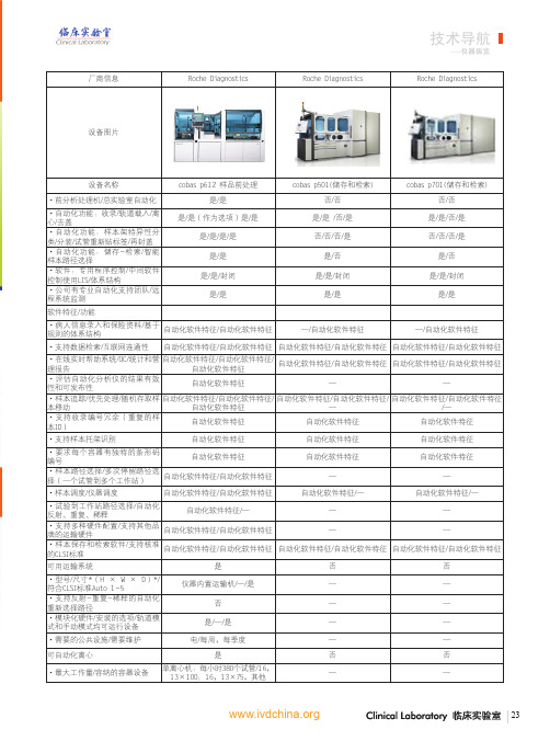
实验室自动化前处理设备纵览
LIS特征/自动化软件特征
LIS特征/自动化软件特征
—
·支持数据检索/互联网连通性
自动化软件特征/—
LIS特征/—
自动化软件特征/—
·在线实时帮助系统/QC/统计和管 自动化软件特征/—/自动化软件特 自动化软件特征/ LIS特征/自动化
理报告
征
软件特征
自动化软件特征/LIS特征/—
·评估自动化分析仪的结果有效性 和可发布性
厂商信息
Roche Diagnostics
Roche Diagnostics
技术导航
——仪器纵览
Roche Diagnostics
设备图片
设备名称
cobas p612 样品前处理
cobas p501(储存和检索)
cobas p701(储存和检索)
·前分析处理机/总实验室自动化
是/是
否/否
否/否
·自动化功能:收录/轨道载入/离 心/去盖 ·自动化功能:样本架特异性分 类/分装/试管重新贴标签/再封盖 ·自动化功能:储存-检索/智能 样本路径选择 ·软件:专用程序控制/中间软件 控制使用LIS/体系结构 ·公司有专业自动化支持团队/远 程系统监测
自动化软件特征/自动化软件特征
LIS(s)和接口的版本以及现场w/ LAS/ LIS(s)如何与您的LAS接合
Cerner, Misys, Modulus, Data Innovations, SCC, Atlas, McKesson/
HL7, ASTM
SCC,
Siemens, Philips/ASTM, Processor
合CLSI标准Auto1-5/平均工作量**
73 × 53英寸/是/1,200
智能触摸芯片 CPT2610 数据手册说明书

CHIPHOMER TECHNOLOGY (SHANGHAI) LIMITEDCPT2610 数据手册单/双通道电容性触摸检测芯片September 2019目录CPT2610 数据手册 (1)目录 (2)图目录 (3)1概述 (4)2引脚 (5)2.1引脚排列 (5)2.2引脚说明 (6)3典型应用 (7)3.1双通道典型应用图 (7)3.2单通道典型应用图 (7)4功能描述 (8)4.1按键状态 (8)4.1.1按键输出有效电平选择 (8)4.1.2CPT2610SP8、CPT2610DN8 按键状态获取 (8)4.1.3CPT2610ST6、CPT2610DN6 按键状态获取 (8)4.2按键扫描模式 (8)4.3长时按键触发解除功能 (8)5电气特性 (9)6封装 (10)6.1SOP8L (10)6.2DFN2X2-8L (11)6.3SOT23-6L (12)6.4DFN1.6X1.6-6L (13)7订货信息 (14)8版本信息 (15)图目录图1CPT2610 SOP8L 引脚排列图 (5)图2CPT2610 SOT23-6L引脚排列图 (5)图3CPT2610 DFN1.6X1.6-6L引脚排列图 (5)图4CPT2610 DFN2X2-8L引脚排列图 (5)图5双通道触摸典型应用图 (7)图6单通道触摸典型应用图 (7)图7SOP8L封装尺寸图 (10)图8DFN2X2-8L封装尺寸图 (11)图9SOT23-6L封装尺寸图 (12)图10DFN1.6X1.6-6L封装尺寸图 (13)1 概述CPT2610是一款低功耗双通道/单通道电容检测芯片,具有高效的RF噪音抑制功能,能够准确识别手指触摸引起的微小电容变化,适用于用触摸按键替代机械按键等应用场合;具有实时的自校准和基线跟踪算法,能有效避免因环境因素变化而引起按键误触等情况;支持输出有效电平选择,以满足不同系统平台及应用的要求。
康普斯压缩机分类大全-康普斯压缩机有限公司驻成都办事处

康普斯压缩机分类大全
/shop-20882/一、康普斯SEP系列/双螺杆电动移动式压缩机
SEP210E SEP系列
SEP850G SEP系列
SEP700E SEP系列
二、康普斯SDP系列/双螺杆柴油移动式压缩机
SDP530G SDP系列
SDP350E SDP系列
三、康普斯SMP系列/双螺杆煤矿用防爆压缩机
SMP1060E SMP系列
SMP710 SMP系列
四、康普斯SEF低压系列/双螺杆电动固定式压缩机
SEF210 SEF系列
SEF350 SEF系列
SEF105 SEF系列
SEF35 SEF系列
五、康普斯SEF系列/双螺杆电动固定侧连式压缩机
SEF210 SEF系
SEF350 SEF系
SEF105 SEF系
SEF35 SEF系
六、康普斯SEF系列/双螺杆电动固定直连式压缩机(水、风冷)
SEF210Z
七、康普斯KPS空气净化系统
KPS空气净化系统
康普斯压缩机有限公司驻成都办事处提供。
2015招标凯斯普120参数
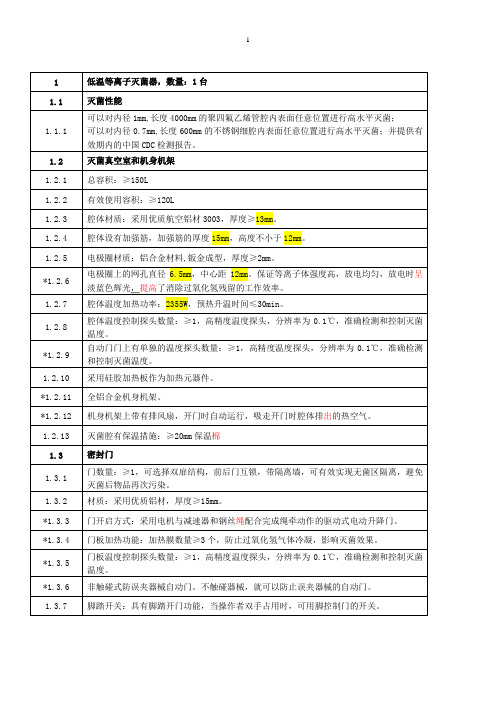
1 低温等离子灭菌器,数量:1台1.1 灭菌性能1.1.1 可以对内径1mm,长度4000mm的聚四氟乙烯管腔内表面任意位置进行高水平灭菌;可以对内径0.7mm,长度600mm的不锈钢细腔内表面任意位置进行高水平灭菌;并提供有效期内的中国CDC检测报告。
1.2 灭菌真空室和机身机架1.2.1 总容积:≥150L1.2.2 有效使用容积:≥120L1.2.3 腔体材质:采用优质航空铝材3003,厚度≥13mm。
1.2.4 腔体设有加强筋,加强筋的厚度15mm,高度不小于12mm。
1.2.5 电极圈材质:铝合金材料,钣金成型,厚度≥2mm。
*1.2.6 电极圈上的网孔直径6.5mm,中心距12mm。
保证等离子体强度高,放电均匀,放电时呈淡蓝色辉光,提高了消除过氧化氢残留的工作效率。
1.2.7 腔体温度加热功率:2355W,预热升温时间≤30min。
1.2.8 腔体温度控制探头数量:≥1,高精度温度探头,分辨率为0.1℃,准确检测和控制灭菌温度。
*1.2.9 自动门门上有单独的温度探头数量:≥1,高精度温度探头,分辨率为0.1℃,准确检测和控制灭菌温度。
1.2.10 采用硅胶加热板作为加热元器件。
*1.2.11 全铝合金机身机架。
*1.2.12 机身机架上带有排风扇,开门时自动运行,吸走开门时腔体排出的热空气。
1.2.13 灭菌腔有保温措施:≥20mm保温棉1.3 密封门1.3.1 门数量:≥1,可选择双扉结构,前后门互锁,带隔离墙,可有效实现无菌区隔离,避免灭菌后物品再次污染。
1.3.2 材质:采用优质铝材,厚度≥15mm。
*1.3.3 门开启方式:采用电机与减速器和钢丝绳配合完成绳牵动作的驱动式电动升降门。
*1.3.4 门板加热功能:加热膜数量≥3个,防止过氧化氢气体冷凝,影响灭菌效果。
*1.3.5 门板温度控制探头数量:≥1,高精度温度探头,分辨率为0.1℃,准确检测和控制灭菌温度。
*1.3.6 非触碰式防误夹器械自动门。
美国爱尔登(Eaton)烧烤布告板拨码集装箱安装说明说明书
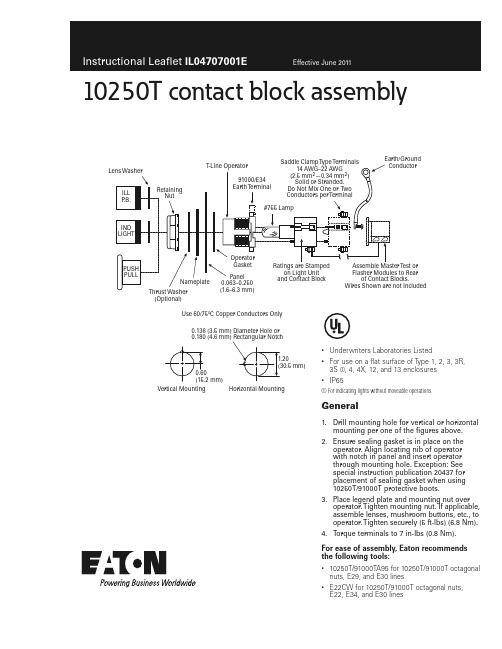
10250T contact block assembly•Underwriters Laboratories Listed•For use on a flat surface of Type 1, 2, 3, 3R, 3S ቢ, 4, 4X, 12, and 13 enclosures •IP65ቢ For indicating lights without moveable operations.General1. Drill mounting hole for vertical or horizontalmounting per one of the figures above.2. Ensure sealing gasket is in place on theoperator. Align locating nib of operator with notch in panel and insert operator through mounting hole. Exception: See special instruction publication 20437 for placement of sealing gasket when using 10250T/91000T protective boots.3. Place legend plate and mounting nut overoperator. Tighten mounting nut. If applicable, assemble lenses, mushroom buttons, etc., to operator. Tighten securely (5 ft-lbs) (6.8 Nm).4. Torque terminals to 7 in-lbs (0.8 Nm).For ease of assembly, Eaton recommends the following tools:•10250T/91000TA95 for 10250T/91000T octagonal nuts, E29, and E30 lines•E22CW for 10250T/91000T octagonal nuts,E22, E34, and E30 lines(Optional)T est orEarth/Ground 0.136 (3.5 mm) Diameter Hole or Use 60/75ºC Copper Conductors OnlyVertical MountingHorizontal MountingEaton Corporation Electrical Sector 1111 Superior Ave.Cleveland, OH 44114United States877-ETN-CARE (877-386-2273)© 2011 Eaton Corporation All Rights Reserved Printed in USAPublication No. IL04707001E / Z11206June 2011Eaton is a registered trademark of Eaton Corporation.All other trademarks are property of their respective owners.Instructional Leafl et IL04707001EEffective June 201110250T contact block assemblyPush–pull operatorsApplication guideTo assist in the selection of contact blocks, the diagram on page 1 shows pictorially by symbols “A ” and “B” locations of contactcircuits after assembly of contact blocks to the operator. T able 1 and T able 2 show the effect of the push and pull operations on either NO or NC contacts.A maximum of two contact blocks may be used with each operator. Maximum torque of stacking screws is 9 in-lbs. Adding more than two blocks may cause this switch to malfunction. Single circuit contact must be mounted under circuit “A ”. Special function contact blocks are not available for use with the three-position push–pull operator.ote: N Buttons and lenses in various colors are ordered and packaged sepa-rately. This pushbutton unit is oiltight when the adapter gasket and button or lens gasket are securely tightened.T able 1. P ush–Pull Operator T ypesOperator TypeContactBlock CircuitOperator Mode and Contact CircuitPulled Intermediate Pushed Circuits A BCircuits A BCircuits A BMomentary push and pull andmomentary pull,maintained push 2NC 1NO X X O O X OO O X Maintained push and pull (Two-positions)1NC 2NC 1NO 2NOX or X X X O or O O O Nointermediate position O or O O O O O X X Momentary push and pull (Three-positions)1NO–1NC O XO OX Oote: N X = contacts closed; O = contacts openT able 2. P ush–Pull Wire Position OperationControlLine DiagramOperatorCircuitsOperator ModeThree-wire,three-position,momentaryMomentary push and pull2NC contactblocksSTARTNormal positionSTOP Two-wire,two-position,maintainedMaintained push and pull1NC contactblocksSTART (Maintained)Nointermediate positionSTOP (Maintained)Three-wire momentary pull,maintained pushMaintained push and maintained ready,momentary pull to start2NC contactblocksSTARTNormal positionSTOP。
Modicon M221 TM221C16R 产品数据手册说明书
TM221C16R.i s c l ai m e r : T h i s d o c u m e n t a t i o n i s n o t i n t e n d e d a s a s u b s t i t u t e f o r a n d i s n o t t o b e u s e d f o r d e t e r m i n i n g s u i t a b i l i t y o r r e l i a b i l i t y o f t h e s e p r o d u c t s f o r s p e c i f i c u s e r a p p l i c a t i o n sProduct datasheetCharacteristicsTM221C16Rcontroller M221 16 IO relayMainRange of productModicon M221Product or component type Logic controller [Us] rated supply voltage 100...240 V ACDiscrete input number 9 discrete input conforming to IEC 61131-2 Type 1Analogue input number 2 at input range: 0...10 V Discrete output type Relay normally open Discrete output number 7 relay Discrete output voltage 5...125 V DC 5...250 V AC Discrete output current2 AComplementaryDiscrete I/O number16Number of I/O expansion module <= 4 for transistor output <= 4 for relay output Supply voltage limits 85...264 V Network frequency 50/60 Hz Inrush current<= 40 APower consumption in VA <= 46 VA at 100...240 V with max number of I/O expansion module <= 31 VA at 100...240 V without I/O expansion module Power supply output current 0.325 A at 5 V for expansion bus 0.12 A at 24 V for expansion bus Discrete input logic Sink or source (positive/negative)Discrete input voltage 24 V Discrete input voltage type DC Analogue input resolution 10 bits LSB value 10 mVConversion time1 ms per channel + 1 controller cycle time for analog input Permitted overload on inputs+/- 30 V DC for analog input with 5 min maximum +/- 13 V DC for analog input permanentVoltage state1 guaranteed>= 15 V for inputCurrent state 1 guaranteed>= 2.6 mA for fast input>= 4.2 mA for discrete inputVoltage state 0 guaranteed<= 5 V for inputCurrent state 0 guaranteed<= 1.3 mA for discrete input<= 0.6 mA for fast inputDiscrete input current7 mA for discrete input5 mA for fast inputInput impedance 4.9 kOhm for fast input3.4 kOhm for discrete input100 kOhm for analog inputResponse time10 ms turn-on operation for output35 µs turn-off operation for input; I2...I5 terminal10 ms turn-off operation for output5 µs turn-on operation for fast input; I0, I1, I6, I7 terminal35 µs turn-on operation for input; other terminals terminal5 µs turn-off operation for fast input; I0, I1, I6, I7 terminal100 µs turn-off operation for input; other terminals terminal Configurable filtering time0 ms for input12 ms for input3 ms for inputOutput voltage limits125 V DC277 V ACCurrent per output common 6 A at COM 1 termnal7 A at COM 0 termnalAbsolute accuracy error+/- 1 % of full scale for analog inputElectrical durability Inductive AC-15, (cos phi = 0.35) 240 V / 120 VA : 100000 cyclesResistive DC-12, 24 V / 48 W : 100000 cyclesResistive AC-12, 120 V / 240 VA : 100000 cyclesInductive AC-15, (cos phi = 0.35) 240 V / 36 VA : 300000 cyclesResistive AC-12, 120 V / 80 VA : 300000 cyclesInductive (L/R = 7 ms) DC-13, 24 V / 24 W : 100000 cyclesResistive DC-12, 24 V / 16 W : 300000 cyclesInductive (L/R = 7 ms) DC-13, 24 V / 7.2 W : 300000 cyclesInductive AC-14, (cos phi = 0.7) 240 V / 240 VA : 100000 cyclesInductive AC-15, (cos phi = 0.35) 120 V / 60 VA : 100000 cyclesInductive AC-14, (cos phi = 0.7) 240 V / 72 VA : 300000 cyclesInductive AC-15, (cos phi = 0.35) 120 V / 18 VA : 300000 cyclesResistive AC-12, 240 V / 480 VA : 100000 cyclesInductive AC-14, (cos phi = 0.7) 120 V / 120 VA : 100000 cyclesResistive AC-12, 240 V / 160 VA : 300000 cyclesInductive AC-14, (cos phi = 0.7) 120 V / 36 VA : 300000 cycles Switching frequency20 switching operations/minute with maximum load Mechanical durability>= 20000000 cycles for relay outputMinimum load 1 mA at 5 V DC for relay outputProtection type Without protection at 5 AReset time 1 sMemory capacity256 kB for user application and data RAM with 10000 instructions256 kB for internal variables RAMData backed up256 kB built-in flash memory for backup of application and data Data storage equipment 2 GB SD card optionalBattery type BR2032 lithium non-rechargeable, battery life: 4 yrBackup time 1 year at 25 °C by interruption of power supplyExecution time for 1 KInstruction0.3 ms for event and periodic taskExecution time per instruction0.2 µs BooleanExct time for event task60 µs response timeMaximum size of object areas512 %M memory bits512 %KW constant words255 %TM timers255 %C counters8000 %MW memory wordsRealtime clock WithClock drift<= 30 s/month at 25 °CRegulation loop Adjustable PID regulator up to 14 simultaneous loopsCounting input number 4 fast input (HSC mode) (counting frequency: 100 kHz), counting capacity: 32 bitsControl signal type Frequency meterSingle phaseDual phase (pulse/direction)Dual phase (quadrature)Integrated connection type USB port with connector mini B USB 2.0Non isolated serial link "serial 1" with connector RJ45 and interface RS485Non isolated serial link "serial 2" with connector RJ45 and interface RS232/RS485Supply Serial serial link supply at 5 V 200 mATransmission rate 1.2...115.2 kbit/s (115.2 kbit/s by default) for bus length of 15 m - communication protocol: RS4851.2...115.2 kbit/s (115.2 kbit/s by default) for bus length of 3 m - communication protocol: RS232480 Mbit/s - communication protocol: USBCommunication port protocol USB port : USB protocol - SoMachine-NetworkNon isolated serial link : Modbus protocol master/slave - RTU/ASCII or SoMachine-Network Local signalling 1 LED green for SD card access (SD)1 LED red for BAT1 LED green for SL11 LED green for SL21 LED per channel green for I/O state1 LED red for module error (ERR)1 LED green for PWR1 LED green for RUNElectrical connection Mini B USB 2.0 connector for a programming terminalTerminal block, 3 terminal(s) for connecting the 24 V DC power supplyConnector, 4 terminal(s) for analogue inputsRemovable screw terminal block for inputsRemovable screw terminal block for outputsCable length<= 10 m shielded cable for fast input<= 30 m unshielded cable for output<= 30 m unshielded cable for digital input<= 1 m unshielded cable for analog inputInsulation2300 V AC between output and internal logicNon-insulated between analogue inputs500 V AC between input and internal logicNon-insulated between analogue input and internal logic1500 V AC between supply and ground500 V AC between sensor power supply and ground500 V AC between input and ground1500 V AC between output and ground2300 V AC between supply and internal logic500 V AC between sensor power supply and internal logic500 V AC between Ethernet terminal and internal logic2300 V AC between supply and sensor power supplyMarking CESensor power supply DC at 250 mA supplied by the controllerMounting support Top hat type TH35-15 rail conforming to IEC 60715Top hat type TH35-7.5 rail conforming to IEC 60715Plate or panel with fixing kitHeight90 mmDepth70 mmWidth95 mmProduct weight0.346 kgEnvironmentStandards EN/IEC 61010-2-201EN/IEC 61131-2EN/IEC 60664-1Product certifications RCMIACS E10DNV-GLcULusCSALRABSEACEnvironmental characteristic Ordinary and hazardous locationResistance to electrostatic discharge 4 kV on contact conforming to EN/IEC 61000-4-28 kV in air conforming to EN/IEC 61000-4-2Resistance to electromagnetic fields10 V/m ( 80 MHz...1 GHz) conforming to EN/IEC 61000-4-33 V/m ( 1.4 GHz...2 GHz) conforming to EN/IEC 61000-4-31 V/m ( 2...2.7 GHz) conforming to EN/IEC 61000-4-3Resistance to magnetic fields 30 A/m at 50...60 Hz conforming to EN/IEC 61000-4-8Resistance to fast transients2 kV for power lines conforming to EN/IEC 61000-4-42 kV for relay output conforming to EN/IEC 61000-4-41 kV for Ethernet line conforming to EN/IEC 61000-4-41 kV for serial link conforming to EN/IEC 61000-4-41 kV for I/O conforming to EN/IEC 61000-4-4Surge withstand2 kV for power lines (AC) in common mode conforming to EN/IEC 61000-4-52 kV for relay output in common mode conforming to EN/IEC 61000-4-51 kV for I/O in common mode conforming to EN/IEC 61000-4-51 kV for shielded cable in common mode conforming to EN/IEC 61000-4-50.5 kV for power lines (DC) in differential mode conforming to EN/IEC 61000-4-51 kV for power lines (AC) in differential mode conforming to EN/IEC 61000-4-51 kV for relay output in differential mode conforming to EN/IEC 61000-4-50.5 kV for power lines (DC) in common mode conforming to EN/IEC 61000-4-5Resistance to conducted disturbances,induced by radio frequency fields10 Vrms (0.15...80 MHz) conforming to EN/IEC 61000-4-63 Vrms (0.1...80 MHz) conforming to Marine specification (LR, ABS, DNV, GL)10 Vrms (spot frequency (2, 3, 4, 6.2, 8.2, 12.6, 16.5, 18.8, 22, 25 MHz)) conforming to Marine specification (LR, ABS, DNV, GL)Electromagnetic emissionConducted emissions conforming to EN/IEC 55011 power lines (AC), 0.15...0.5 MHz : 79 dBμV/m QP/66 dBμV/m AVConducted emissions conforming to EN/IEC 55011 power lines (AC), 0.5...300 MHz : 73 dBμV/m QP/60 dBμV/m AVConducted emissions conforming to EN/IEC 55011 power lines, 10...150 kHz : 120...69 dBµV/m QP Conducted emissions conforming to EN/IEC 55011 power lines, 150 kHz...1.5 MHz : 79...63 dBμV/m QPConducted emissions conforming to EN/IEC 55011 power lines, 1.5...30 MHz : 63 dBμV/m QP Radiated emissions conforming to EN/IEC 55011 class A 10 m, 30...230 MHz : 40 dBμV/m QP Radiated emissions conforming to EN/IEC 55011 class A 10 m, 200 MHz...1 GHz : 47 dBμV/m QP Immunity to microbreaks10 msAmbient air temperature for operation -10...55 °C for horizontal installation -10...35 °C for vertical installation Ambient air temperature for storage -25...70 °CRelative humidity 10...95 % without condensation in operation 10...95 % without condensation in storage IP degree of protection IP20 with protective cover in place Pollution degree <= 2Operating altitude 0...2000 m Storage altitude 0...3000 mVibration resistance3.5 mm (vibration frequency: 5...8.4 Hz) on symmetrical rail 1 gn (vibration frequency: 8.4...150 Hz) on symmetrical rail 3.5 mm (vibration frequency:5...8.4 Hz) on panel mounting 1 gn (vibration frequency: 8.4...150 Hz) on panel mounting Shock resistance98 m/s² (test wave duration:11 ms)Offer SustainabilitySustainable offer status Green Premium productRoHS (date code: YYWW)Compliant - since 1415 - Schneider Electric declaration of conformity Schneider Electric declaration of conformity REAChReference not containing SVHC above the threshold Reference not containing SVHC above the threshold Product environmental profileAvailableProduct environmental Product end of life instructionsAvailableEnd of life manualProduct datasheetTM221C16R Dimensions DrawingsDimensionsProduct datasheetTM221C16R Mounting and ClearanceMounting on a RailProduct datasheetMounting and ClearanceTM221C16RDirect Mounting on a Panel Surface(1)Install a mounting stripMounting Hole LayoutProduct datasheetTM221C16R Mounting and ClearanceMountingCorrect Mounting PositionAcceptable Mounting PositionIncorrect Mounting PositionProduct datasheetTM221C16R Mounting and ClearanceClearanceDigital InputsWiring Diagram (Positive Logic)(*)Type T fuseWiring Diagram (Negative Logic)(*)Type T fuseConnection of the Fast InputsI0, I1, I6, I7Relay OutputsNegative Logic (Sink)(*)Type T fuse(1)The COM1 and COM2 terminals are not connected internally.(2)To improve the life time of the contacts, and to protect from potential inductive load damage, you must connect a free wheeling diode in parallel to each in B Sink wiring (negative logic)Positive Logic (Source)(*)Type T fuse(1)The COM1 and COM2 terminals are not connected internally.(2)To improve the life time of the contacts, and to protect from potential inductive load damage, you must connect a free wheeling diode in parallel to each in A Source wiring (positive logic)Analog InputsUSB Mini-B ConnectionSL1 ConnectionSL1N.C.: not connected* : 5 Vdc delivered by the controller. Do not connect.SL2 ConnectionN.C.: not connectedPerformance CurvesDerating CurvesEmbedded Digital Inputs (No Cartridge)X :Ambient temperatureY :Input simultaneous ON ratioEmbedded Digital Inputs (with Cartridge)X :Ambient temperatureY :Input simultaneous ON ratioTM221C16R.。
CommScope 双极子双包 380-960MHz 1695-2690MHz DC通过高 预配置

Page of 15Twin 2-pak Diplexer, 380–960 MHz/1695–2690 MHz, dc pass highPreconfigured dc pass/blockBTS-to-feeder and feeder-to-antenna applicationThis product will be discontinued on: December 31, 2023Replaced By:E14F05P11Twin 2-pak Diplexer, 380–960 MHz/1695–2690 MHz, dc pass all, with 4.3-10 connectorsProduct ClassificationProduct Type DiplexerGeneral SpecificationsProduct FamilyCBC426ColorGray Common Port LabelANT Modularity2-Twin MountingPole | Wall Mounting Pipe HardwareBand clamps (2)RF Connector Interface7-16 DIN Female RF Connector Interface Body Style Medium neckDimensionsHeight200 mm | 7.874 in Width111 mm | 4.37 in Depth104 mm | 4.094 in Ground Screw Diameter5 mm | 0.197 in Mounting Pipe Diameter Range 40–160 mmOutline DrawingElectrical SpecificationsImpedance50 ohmLicense Band, Band Pass APT 700 | AWS 1700 | CEL 850 | CEL 900 | DCS 1800 | EDD 800 | IMT2100 | IMT 2600 | LMR 750 | LMR 800 | LMR 900 | PCS 1900 | TDD2300 | TDD 2600 | USA 700 | USA 750 | WCS 2300Electrical Specifications, dc Power/Alarmdc/AISG Pass-through, combiner Branch 2dc/AISG Pass-through, demultiplexer Branch 2Lightning Surge Current10 kALightning Surge Current Waveform8/20 waveformElectrical Specifications, AISGAISG Carrier2176 KHz ± 100 ppmInsertion Loss, maximum0.5 dB15 dB25Page ofReturn Loss, minimum15 dBElectrical SpecificationsSub-module 1 | 2 1 | 2Branch12Port Designation PORT 1 380-960PORT 2 1695-2690License Band APT 700, Band PassCEL 850, Band PassCEL 900, Band PassEDD 800, Band PassLMR 750, Band PassLMR 800, Band PassLMR 900, Band PassUSA 700, Band PassUSA 750, Band Pass AWS 1700, Band Pass DCS 1800, Band Pass IMT 2100, Band Pass IMT 2600, Band Pass PCS 1900, Band Pass TDD 2300, Band Pass TDD 2600, Band Pass WCS 2300, Band PassElectrical Specifications, Band PassFrequency Range, MHz380–9601695–2690Insertion Loss, maximum, dB0.150.15Insertion Loss, typical, dB0.10.1Total Group Delay, maximum, ns1010Return Loss, minimum, dB2020Return Loss, typical, dB2323Isolation, minimum, dB5050Input Power, RMS, maximum, W500500Input Power, PEP, maximum, W500050003rd Order PIM, typical, dBc-153-1533rd Order PIM Test Method 2 x 20 W CW tones 2 x 20 W CW tonesBlock DiagramPage of35Environmental SpecificationsOperating Temperature-40 °C to +65 °C (-40 °F to +149 °F)Relative Humidity5%–100%Corrosion Test Method IEC 60068-2-11, 30 daysIngress Protection Test Method IEC 60529:2001, IP67Packaging and WeightsIncluded Mounting hardwareVolume 2.3 LWeight, net 3.8 kg | 8.378 lbRegulatory Compliance/CertificationsAgency ClassificationISO 9001:2015Designed, manufactured and/or distributed under this quality management system45Page of55 Page of。
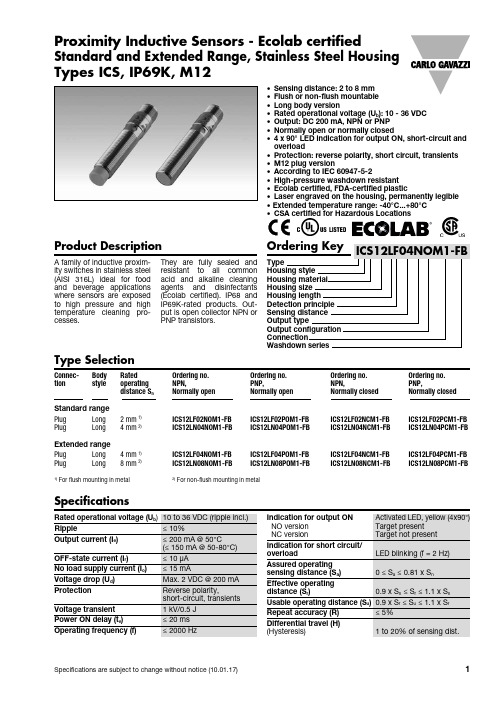
ICS, IP69K, M12 产品系列说明说明书
ICS, IP69K, M12Product DescriptionType SelectionConnec- Body RatedOrdering no. Ordering no. Ordering no. Ordering no.tion style operating NPN,PNP,NPN,PNP,distance S n Normally openNormally openNormally closedNormally closedStandard range Plug Long 2 mm 1) ICS12LF02NOM1-FB ICS12LF02POM1-FB ICS12LF02NCM1-FB ICS12LF02PCM1-FBPlug Long 4 mm 2) ICS12LN04NOM1-FB ICS12LN04POM1-FB ICS12LN04NCM1-FB ICS12LN04PCM1-FB Extended range Plug Long 4 mm 1) ICS12LF04NOM1-FB ICS12LF04POM1-FB ICS12LF04NCM1-FB ICS12LF04PCM1-FB Plug Long8 mm 2)ICS12LN08NOM1-FB ICS12LN08POM1-FB ICS12LN08NCM1-FB ICS12LN08PCM1-FB1)For flush mounting in metal 2)For non-flush mounting in metalStandard and Extended Range, Stainless Steel Housing Types ICS, IP69K, M12A family of inductive proxim-ity switches in stainless steel (A I S I316L) ideal for food and beverage applications where sensors are exposed to high pressure and high temperature cleaning pro-cesses.They are fully sealed and acid and alkaline cleaning (Ecolab certified). P68 and P69K-rated products. Out-put is open collector NPN or PNP transistors.• Sensing distance: 2 to 8 mm • Flush or non-flush mountable • Long body version• Rated operational voltage (U b ): 10 - 36 VDC • Output: DC 200 mA, NPN or PNP • Normally open or normally closed• 4 x 90° LED indication for output ON, short-circuit and overload• Protection: reverse polarity, short circuit, transients • M12 plug version• According to IEC 60947-5-2• High-pressure washdown resistant • Ecolab certified, FDA-certified plastic• Laser engraved on the housing, permanently legible • Extended temperature range: -40°C...+80°CProximity Inductive Sensors - Ecolab certifiedSpecificationsICS, IP69K, M12Specifications (cont.)Dimensions (mm)LED (4 x 90°)38.76.29.610.364.832.56.29.610.36.2LED (4 x 90°)Flush mountable proximity switches, when installed indamping material, must be according to Picture 1A.Non-flush mountable proximity switches, when installed in damping material, must be according to Picture 1B.InstallationICS, IP69K, M12Installation (cont.)Flush mountable proximity switches, when installed togetherin damping material, must be according to Picture 2A.Non-flush mountable proximity switches, when installed together in damping material, must be according to PictureFor sensors installed opposite each other, a minimum space of 6 x S n (the nominal sensing distance) must be observed (See Wiring DiagramICS, IP69K, M12 Reduction FactorsThe rated operating distance is reduced by the use of metals and alloys other than Fe360.The most important reduc-tion factors for inductive proximity sensors are shown in Picture 4.Fe360 : SteelCrNi : Chrome-nickel CuZn : BrassIP69K Connector CablesDelivery Contents • Inductive proximity switch ICS.• 2 nuts stainless steel• Packaging: plastic bag。
PST-12系列操作箱说明书EN
PST-12 Series Operation BoxTechnical InstructionsOperation Instructions GUODIAN NANJING AUTOMATION CO.,LTDSafety StandardThe PST-12 Series Operation Box conforms to the following various safety standards.IEC60255-5: 2000Electrical Relays - Part 5: Insulation coordination for measuring relays and protection equipment - Requirements and testsIEC60255-22-2: 1996Electrical relays - Part 22: Electrical disturbance tests for measuring relays and protection equipment - Section 2: Electrostatic discharge testsIEC60255-22-4: 2002Electrical relays - Part 22-4: Electrical disturbance tests for measuring relays and protection equipment - Electrical fast transient/burst immunity testIEC61000-4-5: 2005Electromagnetic compatibility (EMC) - Part 4-5: Testing and measurement techniques - Surge immunity testIEC61000-4-8: 2001Electromagnetic compatibility (EMC) - Part 4-8: Testing and measurement techniques - Power frequency magnetic field immunity testIEC61000-4-9: 2001Electromagnetic compatibility (EMC) - Part 4-9: Testing and measurement techniques - Pulse magnetic field immunity testIEC60255-22-1: 2005Electrical relays - Part 22-1: Electrical disturbance tests for measuring relays and protection equipment - 1 MHz burst immunity testsIEC60068-2-1: 1990Environmental testing - Part 2: Tests. Tests A: ColdIEC60068-2-2: 1974Environmental testing - Part 2: Tests. Tests B: Dry heatIEC 60068-2-56:1988Environmental testing for electric and electronic products - Part 2:Test methods - Test Cb:Damp heat,steady state,primarily for equipmentIEC60255-21-1: 1988Electrical relays - Part 21: Vibration, shock, bump and seismic tests on measuring relays and protection equipment - Section One: Vibration tests (sinusoidal)IEC60255-21-2: 1988Electrical relays - Part 21: Vibration, shock, bump and seismic tests on measuring relays and protection equipment - Section Two: Shock and bump testsIEC60255-21-2: 1988Electrical relays - Part 21: Vibration, shock, bump and seismic tests on measuring relays and protection equipment - Section Two: Shock and bump testsPart I Technical Instructions1. Brief introduction to the devicePST-12 series operation box has been designed according to operation requirements for protection of new digital transformer. This series operation box is mainly suitable for protection of single or dual tripping coils, split phase or 3-phase circuit breaker operation mechanism and transformer proper etc.This series operation box can perform auxiliary operation of circuit breakers, monitor their status, perform switching of voltage transformer output AC voltages, and realize connection and matching between protection device and circuit breakers. To realize switching function for AC voltages output by voltage transformer, independent chassis can also be used.This series operation box can be configured along with PST-1200 series digital transformer protection device or independently.Wiring principle of this series operation box meets specification in “Unified design descriptions for operation box” proposed by “Unified design for HV line protection device” work team, as well as counter-accident measures for electric power system relay protection. 1.1 Device models and functional configuration1.1.1 PST-1210A proper protection deviceThis device is a fully non-electric protection unit that can provide access of at most 42 lines of non-electric signals and 21 lines of outlet. It is suitable for protection of 500KV voltage grade transformer or reactor proper.1.1.2 PST-1210B operation box and proper protection deviceThis device includes non-electric signal protection, and protection for IV side and LV side circuit breaker operation circuits (circuit breakers with 3-phase ganged single tripping coil). V oltage switching card, bypass voltage monitoring card, and tap-temperature transformer card etc. can be added. Non-electric protection can provide at most access of 12 lines of non-electric signals and 7 lines of outlet. This device is suitable for 500KV~220KV voltage grade transformers.1.1.3 PST-1210C operation box and proper protection deviceThis device includes non-electric signal protection, and protection for HV side, IV side and LV side circuit breaker operation circuits (circuit breakers with 3-phase ganged single tripping coil). V oltage switching card, bypass voltage monitoring card, and tap-temperature transformer card etc. can be added. Non-electric protection can provide at most access of 12 lines of non-electric signals and 7 lines of outlet. This device is suitable for 110KV~35KV voltage grade transformers.1.1.4 PST-1212 3-phase dual tripping operation boxThis device is a circuit breaker operating circuit suitable for 35KV~500KV voltage grade dual bus with bypass wiring mode and circuit breakers with two tripping coils and 3-phase ganged action.1.1.5 PST-1221 split-phase single tripping operation boxThis device is a circuit breaker operating circuit suitable for 220KV~500KV dual bus with bypass wiring mode and circuit breakers with single tripping coil and split-phase action.1.1.6 PST-1222 split-phase dual tripping operation boxThis device is a circuit breaker operating device suitable for 220KV~500KV dual bus with bypass wiring mode and circuit breakers with two tripping coils and split-phase action.1.2 Device features● First class anti-interference design concept; all cards are rear inserted to provide a nice outlook; more important, overall resistance against interference is provided;● Relays of internationally famous manufacturer (National of Japan) are selected, fully satisfying the strictest requirements on reliability;● In the cards, relays and rear terminals are all directly welded on PCB, eliminating wire connection and reducing possible mistake. Reliability and stability of operation box operation are further improved;● Flexible configuration: in addition to configuration listed in section 1.1, combination configuration can be provided for different types of operation mechanism or requirements.·2Technical parameters·2. Technical parameters2.1 Rated parameters2.1.1 Rated DC voltage: 220V or 110V (specify when ordering)2.1.2 Rated make/break current:Rated breaking current: 0.5A, 1A, 1.5A, 2A, 2.5A, 3A, 3.5A, 4A, and higherRated making current: 0.5A, 1A, 1.5A, 2A, 2.5A, 3A, 3.5A、4A and higher.2.2 Normal operating conditions2.2.1 Ambient temperature: -10℃~+55℃2.2.2 Relative humidity: 5%~95%2.2.3 Atmospheric pressure: 66kPa~110kPa2.3 Technical performance2.3.1 Power consumption: not greater than 40W (excluding power consumption by tripping and closing of circuit breakers)2.3.2 Relay action time: not greater than 10ms (under normal atmospheric conditions and rated voltage)2.3.3 Relay contact capacity:Signal circuit contact capacity and parameters (DC): 220V, 0.3A inductive (τ=5ms) 50W, 100,000 times;Outlet circuit contact capacity and parameters (DC): 220V, 0.4A inductive (τ=5ms) 50W, 100,000 times.2.3.4 Effect of DC power supply: This device is capable of normal operation with DC voltage varying in the range of 80%~110% rated voltage.·3 Device structure·3. Device structure3.1 Chassis structureOutline of this series device is 10inch 4U standard chassis (or 4U half layer chassis). Integrated panel and rear insertion structure is used.Rear insertion structure means that cards are plugged and unplugged at rear of the device. Connecting lines among sockets are integrated on a motherboard located at front of the chassis. Open the front panel to see model of the mother board. This structure features the following:a) Each card has its own terminal that can be plugged or unplugged. Resistance to interference, reliability and safety are improved.b) Mother board wiring is arranged according to bus mode so that this device is highly flexible in functional configuration. Functions can be expanded or modified according to user requirements.3.2 Main modulesThis series device consists of the following modules: proper signal card (BT), proper outlet card (CK), 3-phase ganged action single tripping coil circuit breaker monitoring card(PST-1210), tap-temperature transformer card (DWB), bypass (backup) voltage switching card (ZJ), AC voltage switching card (YQJ), DC power switching card (JJ), pressure blocking card (YJJ), manual operation card (STH), tripping/closing position card (TWJ/HWJ/THWJ) and tripping/closing circuit card (TBJ) etc.3.3 Device arrangement drawings3.3.1 Panel arrangement drawings: refer to Part 2 “Operation instructions”3.3.2 Rear board arrangement drawings: refer to Part 2 “Operation instructions”3.3.3 Electric schematic diagram: refer to Part 2 “Operation instructions”3.3.4 Single board schematic diagram: refer to Part 2 “Operation instructions”Part II Operation instructions1 Panel arrangement drawingsPanels listed in this part are all configured panels for standard fixed models. These are included here for user reference only.1.1 PST-1210A proper protection device panel diagram1.2 PST-1210B operation box and proper protection device panel diagram1.3 PST-1210C operation box and proper protection device panel diagram1.4 PST-1212 3-phase dual tripping operation box panel diagram1.5 PST-1221 split-phase single tripping operation box panel diagram·Panel arrangement drawings·1.6 PST-1222 split-phase dual tripping operation box panel diagram1.7 PST-1218 voltage switching device panel diagram32 Rear board arrangement drawingsRear boards listed in this part are all configured rear boards of common models. These are provided here for user reference. Power supply of each circuit is independent.For PST-1210A device: If transformer proper does not have 42 lines of signal contacts, cards NO.14 and NO.13 can be used as backup cards. Or, according to actual configuration, use backup card to replace BT card. In addition, if there are many circuit breakers to be tripped, CK board can be used to replace BT board at NO.14 position. Just replace card mother board at the same time.For PST-1210B device: At IV side, voltage switching and bypass (backup) voltage switching cards can be added. At LV side, PST-1210 card can be added on two branches, and replace with “low 1 branch operation box” and “low 2 branch operation box”. When non-voltage regulating transformer and temperature transformer are hung outside, DWB card can be cancelled.For PST-1210C device: At HV side, voltage switching card can be added. Or, add PST-1210 card and HV side bridge operation box.User can also combine each operation circuit at will according to actual conditions of each substation.2.1 PST-1210A proper protection device rear board diagram452.2 PST-1210B operation box and proper protection device rear board diagram2.3 PST-1210C operation box and proper protection device rear board diagram2.4 PST-1212 3-phase dual tripping operation box rear board diagram2.5 PST-1221 split-phase single tripping operation box rear board diagram 2.6 PST-1222 split-phase dual tripping operation box rear board diagram2.7 PST-1218 voltage switching device rear board diagram6·3 Annex I·4 Annex II3 Annex I: Typical wiring electric schematic diagramThis section only lists typical wiring electric schematic diagrams for operation boxes PST-1222, PST-1212 and PST-1221, for reference by user. For actual electric schematic diagrams of each project, project ex-factory drawings shall govern.4 Annex II: Schematic diagram of each single board of operation box7Nanjing, ChinaGuodian Nanjing Automation Co., Ltd.Nanjing Xinning Power Technology Co., Ltd. Address: No.38, New Model Street, Nanjing Postal Code: 210003Tel: (025) 83537517 83537518Fax: (025) 83537500 83434548Client service hotline: (025) 8353751883537509 Website: E-mail: market @ 。
顾客特殊要求识别清单
编制:批准:
每批次交货的单板需有加印白油块(打二维码)
每批次交货的板工艺边大小要一致
交货的板单元大小、链接位、MARK位置不能变动,如有变化需提前通知。
产品订购技术标准
订购技术标准:
依据客户要求
产品规格、数量、名称、品种以订单为准。
产品技术标准以技术资料为准,如没有注明则按送样承认的样品为准。
包装标准
送货的产品需要有送货单、检查报告、装箱清单(需注明p/o号),内外箱不得出现供应商任何信息。
顾客特殊要求识别清单
顾客名称
供应商代码
顾客特殊要求(CSR)
顾客特殊要求内容
本公司的应对方式
协议书
产品验收
各制程与成Leabharlann 检验指示/QAP-12进料检验程序/依据客户要求
依据客户要求
尺寸按照相关数据和图纸
外观按照IPC-A-610H/IPC-6102三级标准验收
测试方法按IPC-TM-650执行
交货的产品需每包真空后有条码识别,大小随机
美国某公司水泥泥土泥浆泵系列产品说明说明书
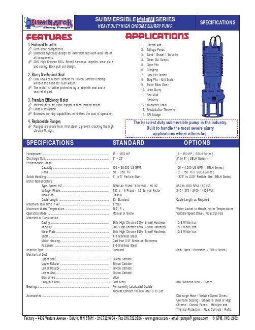
1. Enclosed Impeller Even wear components.Balanced hydraulic design for extended and even wear life of all components.28% High Chrome 650+ Brinell hardness, impeller, wear plate and casing. Back pull out design.2. Slurry Mechanical SealDual Seals of Silicon Carbide vs. Silicon Carbide running without the need for flush water.The motor is further protected by a labyrinth seal and a seal relief port.3. Premium Efficiency MotorInverter duty, air filled, copper wound/formed motor. Class H insulation.Extended run dry capabilities, minimizes the cost of operation.4. Replaceable FlangesFlanges are made from mild steel to prevent cracking the high chrome fittings.Horsepower................................................................................................15 – 1500 HP 15 – 150 HP ( SBLH Series )Discharge Size............................................................................................3” – 20”3” to 8” ( SBLH Series )Performance RangeCapacity................................................................................100 – 20,000 US GPM 100 – 4,500 US GPM ( SBLH Series )Head ......................................................................................50’ – 350’ TH10’ – 160’ TH ( SBLH Series )Solids Handling..........................................................................................1” to 5” Particle Size1.375” to2.50” Particle Size (SBLH Series)Motor NomenclatureType, Speed, HZ ..................................................................TENV Air Filled / 890-1180 / 60 HZ 350 to 1780 RPM / 50 HZ Voltage, Phase......................................................................480 V. / 3 Phase / 1.2 Service Factor 240 / 575 / 2400 / 4160 Volt Insulation ..............................................................................Class H Cable Length........................................................................33’ Standard Cable Length as RequiredMaximum Run Time in Air...................................................................... 1 Year Maximum Water Temperature................................................................180°F. +Water Jacket to Handle Hotter Temperatures Operation Mode ........................................................................................Manual or SnoreVariable Speed Drive / Float Controls Materials of ConstructionCasing....................................................................................28% High Chrome 650+ Brinell Hardness 15/3 White Iron Impeller..................................................................................28% High Chrome 650+ Brinell Hardness 15/3 White Iron Wear Plate............................................................................28% High Chrome 650+ Brinell Hardness 15/3 White IronShaft ......................................................................................416 Stainless SteelMotor Housing......................................................................Cast Iron 3/8” Minimum Thickness Fasteners ..............................................................................316 Stainless Steel Impeller Type..............................................................................................EnclosedSemi-Open - Recessed ( SBLH Series )Mechanical SealUpper Seat............................................................................Silicon Carbide Upper Rotator ......................................................................Silicon Carbide Lower Rotator......................................................................Silicon Carbide Lower Seat............................................................................Silicon Carbide Elastomers............................................................................Viton Labyrinth Seal......................................................................Cast Steel316 Stainless Steel / BronzeBearings......................................................................................................Permanently Lubricated DoubleAngular Contact 100,000 Hour B-10 LifeAccessories ................................................................................................Discharge Hose / Variable Speed Drives / Urethane Coating / Elbows in Steel or High Chrome / Control Panels / Moisture and Thermal Protection / Float Controls / Rafts.FEATURESAPPLICATIONS1.Bottom Ash2.Tailings Ponds3.Sand / Gravel / Taconite4.Clean Out Sumps5.Coke Pits6.Dredging7.Coal Pile Runoff 8.Slag Pits / Mill Scale 9.Boiler Blow Down 10.Lime Slurry 11.Red Mud Recovery12.Thickener Drain13.Precipitation Thickener 14.API SludgeSPECIFICATIONSHEAVY DUTY HIGH CHROME SLURRY PUMPThe heaviest duty submersible pump in the industry.Built to handle the most severe slurryapplications where others fail.SPECIFICATIONSSTANDARDOPTIONSFactory–4432VentureAvenue•Duluth,MN55811•218.722.9904•Fax218.722.2826••email:***************©GPM,INC.2002SUBMERSIBLE SBEW SERIES。
28℃医用冷藏箱hyc-610
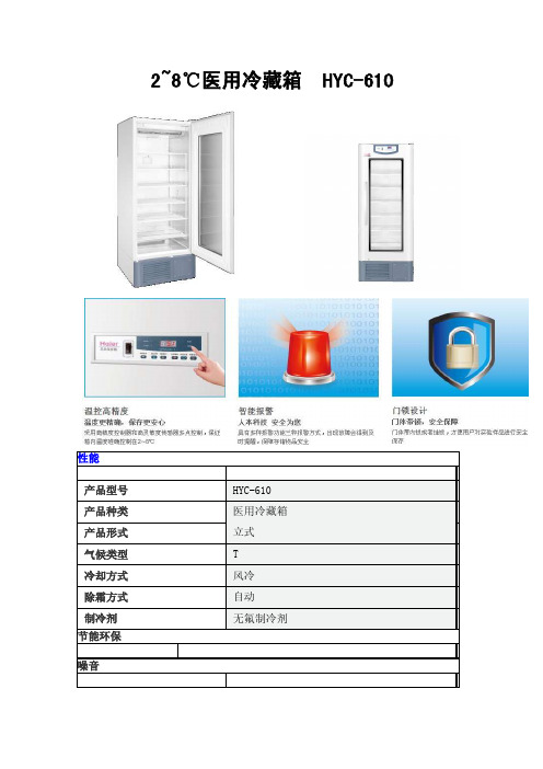
2~8℃医用冷藏箱HYC-610
性能
产品型号HYC-610
产品种类医用冷藏箱
产品形式立式
气候类型T
冷却方式风冷
除霜方式自动
制冷剂无氟制冷剂
节能环保
噪音
噪音(dB) 45
耗电量
功率(W)490
电源参数
电源(V/Hz) 220/50
规格
箱内温度范围(℃)2~8
外形尺寸(宽*深*高)(mm)780*840*1960
内部尺寸(宽*深*高)(mm)680*620*1400
有效容积(L)608
重量(Kg)180
温控方式电脑板温控
温度设定方式数字式(最小调节量0.1)温度显示LED数字式
材料
外部材料彩色涂层钢板
内部材料不锈钢
保温材料普通无氟发泡剂
产品配件
压缩机-类型全密封型
压缩机-功率(W)310
压缩机个数1个
脚轮有
止动底角有
检测孔有
检测孔个数 1
温度传感器热敏电阻温度传感器
内门款式及个数无
外门款式及个数大视角玻璃发泡门体/1个外门锁扣无
锁扣个数 1
搁板材质蘸塑平板搁架
搁架称重(Kg) 50
搁板是否可调是
搁板是否可插标识贴是
记录仪选配
记录仪USB接口选配
功能参数
报警系统有
远程报警有,常开式
温度报警高低温报警
过滤网脏报警无
断电报警有
电压超标报警无
传感器故障报警有
电池电量低报警有
环温超标报警无
开机延迟保护无
显示屏密码保护有
其它
医疗器械注册证有
认证无。
RMX可编程电源供应器安全信息与安装指南说明书
Switchboard Breaker Requirements
• Installation must be done in accordance with national wiring rules, such as NFPA 70 "NEC" and CSA C22.1 "CEC".
• Rated current: 30 A (for safety, breakers whose rated current exceeds 30 A cannot be used) • Do not power any other equipment from the switchboard breaker. • Keep the breaker readily accessible at all times. • Indicate that the breaker is dedicated for use with this product and that it is used to
SAFETY INFORMATION & INSTALLATION GUIDE
RMX Programmable Power Supplies
RMX-4120/4121/4122/4123/4124/4125/4126/4127
About the RMX Safety Information & Installation Guide
The power cord can be used to disconnect the RMX programmable power supply from the AC power line in an emergency. Connect the plug to an easily accessible power outlet so that the plug can be removed from the outlet at any time. Be sure to provide adequate clearance around the power outlet. 1. Check that the AC power line meets the nominal input rating of the product. The product
压缩机CT1022产品说明书

无锡压缩机股份有限公司
ii
CT1022(MH6)使用说明书
版权所有,不得翻印,特别是有关的商标、名称、零件号和图纸,违者必 究。
公司电话:0510-85024889(总机) 公司传真:0510-85012165 Web-site: Email to: office@
重要安全信息........................................................................................................................................................... 2-1
market@
无锡压缩机股份有限公司
中国江苏省无锡市新区鸿山机光电工业园(锡协路东)
无锡压缩机股份有限公司
iii
CT1022(MH6)使用说明书
目次
第1部分 简介 .................................................................................................… 1-1
使用说明书
CT1022/SM-2011
001
无锡压缩机股份有限公司
2011 年 3 月
编制 校对 标准化 审核
职能部门
CT1022(MH6)使用说明书
文件审签
符明董
日期
韩建涛
日期
王妍
日期
陈军
日期
会签
签署
职能部门
2011-03-18 2011-03-18 2011-03-18 2011-03-18
签署
保修......................................................................................................................1-13
飞利浦新纳米CT精华版配置清单和配置说明
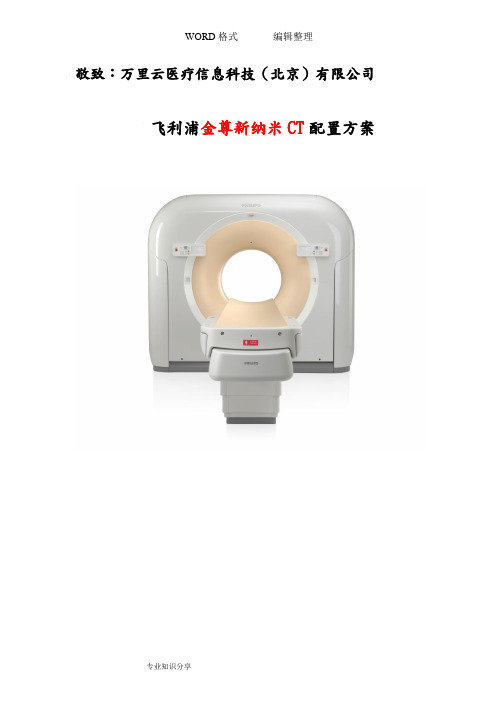
Dedicated Pediatric Protocols婴幼儿专用扫描软件包 八 Console Computer 主台计算机系统 Computer Architecture: Main Memory: 主机内存: 4.7 GB DVD Windows™ Dell™ Precision host computer 主计算机配置: Dell Precision工作站,采用Windows 操作系统 12.0 GB RAM 12.0 GB 双19寸液晶显示器配置 主机 DVD 刻录系统
编辑整理
自动螺旋启动技术(SAS) 自动扫描程序选择软件
图像自动搜索传送软件 自动病例分发
Automatic Procedure Selection 图像处理功能
图像标注,测量分析功能 窗宽窗位控制功能
Maximum or Minimum Intensity Projection (MIP) 3-D SSD Reconstruction Volume Rendering CT Time Lapse Tissue mirror Endo -3D 容积仿真内窥镜 CT时间密度曲线图 组织透镜 三维重建软件包 容积三维重建
2* 19’LCD Monitor
Image Management and Archiving图像管理和存档 Filming照相系统 Networking/Connectivity网络/联接 DICOM Connectivity DICOM 联接 CT injector interface高压注射器接口
最大和最小密度投影
Quantitative CT Measurement 血管定量分析测量软件
高级专业型临床应用软硬件 1 R R CV Toolkit 高级心脏成像软件包 Retrospective Tagging 回顾性心电门控重建 Prospective Gating 前瞻性心电门控采集 Integrated ECG Monitor 多功能监护仪 COBRA™ Adaptive Multi-cycle Reconstruction (Cobra Cardiac) 三维智能自适应多周期 重建 2 3 iDose 星光平台 Ultra High Resolution Matrices 超高分辨率成像技术
CrossChip CC6201 微功耗全极性磁场感应开关说明书
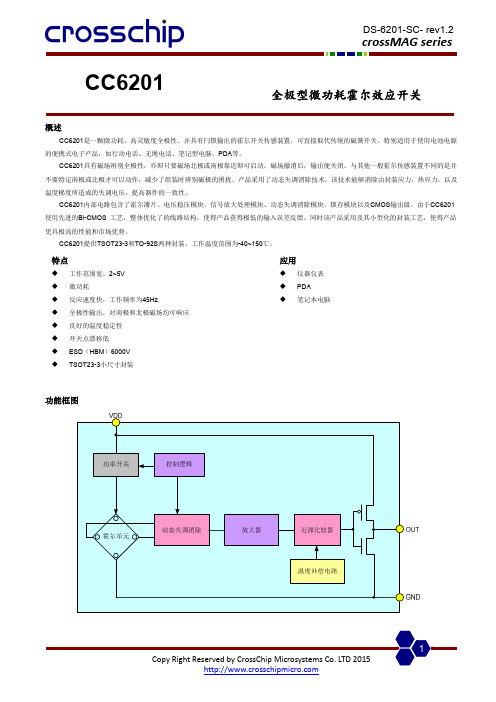
CC6201全极型微功耗霍尔效应开关概述CC6201是一颗微功耗、高灵敏度全极性、并具有闩锁输出的霍尔开关传感装置,可直接取代传统的磁簧开关。
特别适用于使用电池电源的便携式电子产品,如行动电话、无绳电话、笔记型电脑、PDA 等。
CC6201具有磁场辨别全极性,亦即只要磁场北极或南极靠近即可启动,磁场撤消后,输出便关闭。
与其他一般霍尔传感装置不同的是并不要特定南极或北极才可以动作,减少了组装时辨别磁极的困扰。
产品采用了动态失调消除技术,该技术能够消除由封装应力,热应力,以及温度梯度所造成的失调电压,提高器件的一致性。
CC6201内部电路包含了霍尔薄片、电压稳压模块、信号放大处理模块、动态失调消除模块、锁存模块以及CMOS 输出级。
由于CC6201使用先进的Bi-CMOS 工艺,整体优化了的线路结构,使得产品获得极低的输入误差反馈。
同时该产品采用及其小型化的封装工艺,使得产品更具极高的性能和市场优势。
CC6201提供TSOT23-3和TO-92S 两种封装,工作温度范围为-40~150℃。
功能框图特点◆ 工作范围宽,2~5V ◆ 微功耗◆ 反应速度快,工作频率为45Hz◆ 全极性输出,对南极和北极磁场均可响应 ◆ 良好的温度稳定性 ◆ 开关点漂移低◆ ESD (HBM )6000V ◆ TSOT23-3小尺寸封装应用◆ 仪器仪表 ◆ PDA ◆笔记本电脑名称 封装型号 备注 CC6201TO TO-92S 袋装,1000片/包 CC6201STTSOT23-3卷盘,3000片/卷开关输出 vs. 磁场极性注意: 磁场加在芯片的丝印面管脚描述名称管脚编号 功能 TO-92STSOT23-3V DD 1 1 电源电压 GND 2 3 地 V OUT32输出参数符号数值单位电源电压V DD-0.3~5V磁场强度 B 无限制Gauss工作环境温度T A-40~150 ℃存储环境温度Ts -50~160 ℃ESD(HBM) 6000 V电气参数(如无特别标明,V=3.5V @ 25°C)DD参数符号测试环境最小值典型值最大值单位输出高电平 V OH I OUT=0.5mA V DD-0.2 - - V输出低电平 V OL I OUT=0.5mA - - 0.2 V开启状态电流 I DD(EN) - 2 - mA关断状态电流 I DD(dis) - 3 - uA平均电流 I DD(average) - 5 - uA启动时间 T awake- 50 100 us扫描周期 T period- 22 - ms占空比 D.C. - 0.2% -磁参数参数符号测试环境最小值典型值最大值单位工作点B OP25 ℃- ±40 - 高斯(Gauss)放点B RP25 ℃- ±32 - 高斯(Gauss)迟滞B HYS25 ℃- 8 - 高斯(Gauss)典型应用电路01020304050600123456f (H z )VDD (V)2468100123456I D D (u A )VDD (V)扫描频率 vs. 工作电压静态电流 vs. 工作电压磁感应点 vs. 环境温度磁感应点 vs. 工作电压(1)TO-92S packageHall 感应点位置注意: 所有单位均为毫米。
- 1、下载文档前请自行甄别文档内容的完整性,平台不提供额外的编辑、内容补充、找答案等附加服务。
- 2、"仅部分预览"的文档,不可在线预览部分如存在完整性等问题,可反馈申请退款(可完整预览的文档不适用该条件!)。
- 3、如文档侵犯您的权益,请联系客服反馈,我们会尽快为您处理(人工客服工作时间:9:00-18:30)。
DOC NO.: CTSOP-M12-61062-01 DOC REV: 1.2 DOC Page:3/68
工序编号
CTSOP-M12-61062-01-13 CTSOP-M12-61062-01-14 CTSOP-M12-61062-01-15 CTSOP-M12-61062-01-16 CTSOP-M12-61062-01-17 CTSOP-M12-61062-01-18 CTSOP-M12-61062-01-19 CTSOP-M12-61062-01-20 CTSOP-M12-61062-01-21 CTSOP-M12-61062-01-22 CTSOP-M12-61062-01-23 CTSOP-M12-61062-01-24
DOC NO.: CTSOP-M12-61062-01 DOC REV: 1.2 DOC Page:4/68
工序编号
CTSOP-M12-61062-01-36 CTSOP-M12-61062-01-37 CTSOP-M12-61062-01-38
工序名称
连接电箱地线2 EOL检测(前中后一起) 电箱气密性检测
使用工具:无线扫描枪 吸尘器 专用螺丝 品质要求: 1 外观清洁,箱体无变形破损,箱体内无铁屑杂物; ▽ 2 箱体底部螺母孔位要居中; 3 等电位接地点无脏污. 注意事项: 1 操作需穿劳保鞋.
Form NO.:QF-T-CTSOP-C
Contemporary Amperex Technology Limited
工序一:电箱与系统条码扫描配对(一)●
物料名称 物料编号 物料用量 物料图片 物料名称 物料编号 物料用量 物料图片
DOC REV: 1.2 DOC Page:5/68
操作步骤: 1 检查来料前箱箱盖支架是否缺失(如上图);
使用工具事项: 1 操作需穿劳保鞋. 2 整篇SOP通用操作规则: a)锁螺栓螺母通用操作:先用手预紧,确保螺栓与螺母螺纹咬合上 b)连接低压线束时,先将连接器端子插好,在固定卡扣。 C)螺栓画线方法:拧紧一个螺栓或螺母就需画线确认一个,且画线需从螺 栓头部或螺母到被紧固件表面,需目视为直线 3 Pack的放置:整个生产过程,pack只能放置到其专用的桌子,禁止放到别 的地方
DOC REV: 1.2 DOC Page:10/68
1
2
操作步骤: 1 先拿出水冷板(图1); 2 扫描下层水冷板及原始条码,将下层水冷板装入箱体内(如图2)。
使用工具:无线扫描枪 品质要求: 1 检查水冷板有没有异物,如有用干净抹布清洁; 2 拿取水冷板注意不要造成水冷板变形; 3 放入水冷板时不要磕碰; ▼ 4 每取一个物料扫描一次。 注意事项: 1 操作需穿劳保鞋。 2 注意防护水冷板被工具等物体损坏
工序名称
安装固定板和开关盒并连接开关 盒负极 固定开关盒支架 安装吸湿片 安装BMU和低压通信线束 安装低压连接器2并连接低压线 束 安装上层模组固定板 安装上层水冷板并预对位 安装箱体加强横梁 固定上层水冷板并接地线 安装上层模组 安装上层模组压条固定模组 固定上层线束支架
Form NO.:QF-T-CTSOP-C
CATL Confidential Information
Surpassing customer’s expectation
DOC NO.: CTSOP-M12-61062-01
工序二:电箱条码扫描启动装配
物料名称 前箱箱体
DOC REV: 1.2 DOC Page:7/68
物料编号 65180-0067 物料用量 物料图片 物料名称 物料编号 物料用量 物料图片 1ea
Form NO.:QF-T-CTSOP-C
Contemporary Amperex Technology Limited Surpassing customer’s expectation
CATL Confidential Information
DOC NO.: CTSOP-M12-61062-01
Yu F/MPE
1.2
1.第一步工序增加支架检查 2.平衡阀安装方向描述在品质要求里面
05/08/2014
Zhang XJ/MPE
Yu F/MPE
Form NO.:QF-T-CTSOP-C
Contemporary Amperex Technology Limited
CATL Confidential Information
Form NO.:QF-T-CTSOP-C
Contemporary Amperex Technology Limited
CATL Confidential Information
安装下层模组
安装下层模组压条固定模组 锁紧下层水冷板法兰盘 连接下层模组电缆线 安装低压连接器1
Contemporary Amperex Technology Limited
CATL Confidential Information
Surpassing customer’s expectation
MUC 电箱前箱组装工作指示
工序四:安装下层吸湿片
物料名称 吸湿片 M6防松螺母
DOC REV: 1.2 DOC Page:9/68
物料编号 63090-000265110-0001 物料用量 物料图片 物料名称 物料编号 物料用量 物料图片 2ea 4ea
操作步骤: 1 将2ea吸湿片放入安装位置,用4eaM6防松螺母从左往右的顺序用扭力批 依次安装,扭力3.0NM(图中蓝色部分)。
工序编号 CTSOP-M12-61062-01-25 CTSOP-M12-61062-01-26 CTSOP-M12-61062-01-27 CTSOP-M12-61062-01-28 CTSOP-M12-61062-01-29 CTSOP-M12-61062-01-30 CTSOP-M12-61062-01-31 CTSOP-M12-61062-01-32 CTSOP-M12-61062-01-33 CTSOP-M12-61062-01-34 CTSOP-M12-61062-01-35 工序名称 预装BMU&BMS&固定架到立式固定板 固定立式固定板组件并锁紧上层水 冷板接头 连接上层模组高压电缆并加线扣固 定 固定开关盒并连接低压通讯线 连接内外水管 安装电箱密封条 安装上层箱盖吸湿片及高压连接器 预装 安装平衡阀&缓冲泡棉 水冷系统气密性检测 flash烧录程序 箱盖涂胶连接电缆高压互锁线并锁 紧
Surpassing customer’s expectation
DOC NO.: CTSOP-M12-61062-01
工序三:连接电箱地线1 ●
物料名称 地线
DOC REV: 1.2 DOC Page:8/68
物料编号 63240-0009 物料用量 物料图片 物料名称 物料编号 物料用量 物料图片 1ea
CATL Confidential Information
Surpassing customer’s expectation
DOC NO.: CTSOP-M12-61062-01
工序五: 安装下层水冷板并对位●
物料名称 下层水冷板 物料编号 65420-0002 物料用量 物料图片 物料名称 物料编号 物料用量 物料图片 1ea
1
使用工具:无线扫描枪 品质要求: 无 注意事项: 1 操作需穿劳保鞋. 操作步骤: 1 扫描Pack标签和箱体物料标签后再扫描原始条码(图1).
Form NO.:QF-T-CTSOP-C
Contemporary Amperex Technology Limited
CATL Confidential Information
Form NO.:QF-T-CTSOP-C
Contemporary Amperex Technology Limited
CATL Confidential Information
Surpassing customer’s expectation
DOC NO.: CTSOP-M12-61062-01
MUC 电箱前箱组装工作指示
适用范围
编号 1 2 3 4 产品编码或名称 610620001 产线或工序名称
DOC NO.: CTSOP-M12-61062-01 DOC REV: 1.2 DOC Page:1/68
其他
Form NO.:QF-T-CTSOP-C
Contemporary Amperex Technology Limited
Form NO.:QF-T-CTSOP-C
Contemporary Amperex Technology Limited
CATL Confidential Information
Surpassing customer’s expectation
DOC NO.: CTSOP-M12-61062-01
Surpassing customer’s expectation
MUC 电箱前箱组装工作指示
工序编号 CTSOP-M12-61062-01-01 CTSOP-M12-61062-01-02 CTSOP-M12-61062-01-03 CTSOP-M12-61062-01-04 CTSOP-M12-61062-01-05 CTSOP-M12-61062-01-06 CTSOP-M12-61062-01-07 CTSOP-M12-61062-01-08 CTSOP-M12-61062-01-09 CTSOP-M12-61062-01-10 CTSOP-M12-61062-01-11 CTSOP-M12-61062-01-12 工序名称 电箱与系统条码扫描配对 电箱条码扫描启动装配 连接电箱地线1 安装下层吸湿片 安装下层水冷板并预对位 安装水冷板法兰盘 固定水冷板并接地线
操作步骤: 1 扫描地线后再扫描原始条码; 2 折弯端子连接到箱体(如图) 3 用箱体自带M6螺母连接电箱地线端子,扭力8.8NM.
