GA30 _GA37_GA45安装资料(包括外形尺寸图案电气原理图)
GA30 ,37 ,45 ,55,75零件手册
内容
零件清单
目录
压缩机机头和传动齿轮 1 .............................................................................................................................. 空气进气 2 ....................................................................................................................................................................................
卸荷阀 3 .................................................................................................................................................................................. 储气罐 4 ..................................................................................................................................................................................
电控柜
-
CSA/UL 17 ................................................................................................................................................................................
WIFI模块-硬件设计资料

WIFI模块硬件设计规格书版本: 1.0目录1 模块总体介绍(Gerneral introduction) (4)1.1 概述及实物图片(Description) (4)1.2 应用领域(Application) (6)1.3 产品特性 (Main feature) (6)2 模块电气特性(Electric Characteristics) (8)2.1 极限条件(Absolute Maximum Ratings) (8)2.2 工作条件(Recommended Operate Range) (8)2.3 电气特性(General Electric Characteristics)............................... (8)2.4 拼脚定义(Pin Assignment and Description) (9)3 模块应用设计指导(Application note) (14)3.1 功能框图(Function Block description) (14)3.2 工作状态描述(state descriptions) (14)3.3 硬件应用接口概述 (15)3.4 电源和驱动应用接口 (16)3.4.1 电源和驱动管脚定义 (16)3.4.2 主电源供电特性Vbat (17)3.4.3 备用电池RTC................................................................................. ........................... (18)3.4.4 开关机及复位(Power ON/OFF and Reset) (19)3.4.5 充电输入口VCHGIN............................ ................................. .. (20)3.4.6 充电输出口VCHGOUT........................... ................................. . (21)3.4.7 电池检测专用ADC口ADC3/BAT_ID ........................... .. (21)3.4.8 4路LDO输出.................................................... .. (22)3.4.9 LED-驱动 (22)3.4.10 KEY_ LED-驱动 (23)3.4.11电源电路参考设计 (23)3.5 按键接口........................................... . (24)3.6 语音接口........................................... (25)3.6.1模拟音频差分输入主MIC0和辅助MIC1.................................................................................. . (25)3.6.2 模拟音频差分输出受话器REC (26)3.6.3 模拟音频差分输出喇叭SPK (26)3.7 UART 接口 (27)3.8 IIC 接口 (28)3.9 LCD IO驱动为2.8V SPI 接口 (28)3.10 LCD IO驱动为1.8V SPI 接口 (29)3.11 USB 接口..................................... . (30)3.12 SIM 卡接口 (31)3.13 T-F卡接口 (32)3.14 F M 接口 (34)3.15 BT 接口 (34)3.16 通用GPIO接口 (35)3.17 中断口EINT (35)3.18 模拟输入ADC (35)3.19 射频天线接口 (36)4硬件设计指南 (37)4.1 PCB板布局说明 (37)4.2 PCB 关键走线说明......................................................... (37)5 机械特性 (38)5.1 模块机械尺寸 (38)5.2 模块产品 Top-View 视图.......................................... (39)5.3模块供电要求及接法 (41)5.4下载软件 (41)5.5模块开机 (41)5.6 RF测试连接 (41)6 附录 (42)6.1 射频指标 (42)6.2 通信专用术语 (42)1 模块总体介绍1.1 概述及实物图片GW01_GSM&WIFI是一款GSM/GPRS/WIFI无线四频(GSM850/GSM900/DCS1800/PCS1900)工业模块,可以覆盖全球通用GSM频段。
士兰微电子 SBD30C45T PN S PS 说明书 30A、45V肖特基整流管 说明书
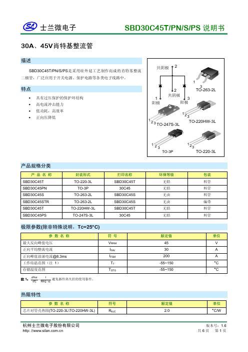
30A 、45V 肖特基整流管描述SBD30C45T/PN/S/PS 是采用硅外延工艺制作而成的肖特基整流二极管,广泛应用于开关电源、保护电路等各类电子线路中。
特点♦ 具有过压保护的保护环结构 ♦ 高电流冲击能力 ♦ 低功耗,高效率 ♦正向压降低产品规格分类产 品 名 称 封装形式 打印名称 环保等级 包装 SBD30C45T TO-220-3L SBD30C45T 无铅 料管 SBD30C45PN TO-3P 30C45 无铅 料管 SBD30C45S TO-263-2L SBD30C45S 无卤 料管 SBD30C45STR TO-263-2L SBD30C45S 无卤 编带 SBD30C45T TO-220HW-3L SBD30C45T 无铅 料管 SBD30C45PSTO-247S-3L30C45无铅料管极限参数(除非特殊说明,T C =25°C)参 数 名 称符 号 额定值 单位 最大反向峰值电压 V RRM 45 V 正向平均整流电流 I FAV 30 A 正向峰值浪涌电流@8.3ms I FSM 200 A 工作结温范围(注 1) T J -55~150 °C 存储温度范围T STG-55~150°C注1:a)Rth(j 1dTjdPtot −<避免器件热失控的使用条件。
热阻特性参 数 名 称符号 额定值 单位 芯片对管壳热阻(TO-220-3L\TO-220HW-3L) R θJC2.0°C/W电参数规格参数符号测试条件最小值最大值单位正向压降V F I F=15A(T C=25°C) -- 0.70 V I F=15A(T C=125°C) -- 0.65V 反向漏电流I RV R=45V(T C=25°C) -- 100 μAV R=45V(T C=125°C) -- 35 mA 典型特性曲线图1. 典型正向特性图2. 典型反向特性瞬态正向电流,IF(A)瞬态正向压降, VF(V)瞬态反向偏压, V R(V)瞬态反向电流,IR(mA)0.010.111010000.10.20.30.40.50.60.70.80.0010.010.110100图3. 结电容特性反向偏压, V R(V)结电容,C J(pF)02545图4. 正向平均整流电流特性正向平均整流电流,IFAV(A)温壳, Tc(°C)520102004008005101520303540151封装外形图封装外形图(续)封装外形图(续)声明:♦士兰保留说明书的更改权,恕不另行通知!客户在下单前应获取最新版本资料,并验证相关信息是否完整和最新。
阿特拉斯GA37

阿特拉斯 GA 37阿特拉斯GA系列微油螺杆式压缩机GA 37GA37 压缩机系列,占地面积小... 性能优越阿特拉斯·科普柯的 WorkPlace Air System? (工作现场型空气系统)提供无与伦比的用户价值。
通过此系统,您可以在使用时直接安装压缩机。
配置可选的内置式干燥器和附件的 GA30 系列变化多样,大小各异。
容量为 4.5-4.6 m3/min,最大工作压力为 7.5 - 13 巴。
型号为 50 Hz 和 60 Hz。
装成本低GA37WorkPlace Air System? (工作现场型空气系统)整体供货,可以实现现场的高效运行。
安装成本极低,是因为 GA 37具备:低噪音水平高效冷却风扇的配备和声振优化技术的应用大大降低了噪音水平,使得在工作现场安装压缩机成为可能。
优质空气产品的完美组合空气干燥器、压缩空气过滤器、冷凝水处理设备和储气罐都可以集成到压缩机组中。
这样可以降低安装成本并显著缩小所需的占地空间。
整体可靠性根据 ISO 9001 和 ISO 14001 设计制造,GA37系列符合业内最高质量标准。
所有装置均符合 ISO 1217, 第3 版, 附件 C – 1996 测试标准。
全球范围的销售和服务组织从概念到安装、从建议到预防性维护和保养活动,阿特拉斯·科普柯与您在维护生产过程的压缩空气领域中通力合作,帮助您生产及扩展业务以致成功。
X 透视图1.传动系统2.冷却风扇3. Elektronikon?控制器4.油气分离器及机油滤清器5.电气柜体6.干燥器阿特拉斯·科普柯获专利的电脑控制器是一种先进的微处理器为核心,直向用户的‘微处理操作系统,GA37采用Elektronikon I电脑。
可靠性友好的用户界面显示友好的服务数字监控通讯·借助于电脑显示屏上的维修保养提示和报警提示,预先对压缩机采取保施·如压缩机问题严重时可安全地关闭压缩机·如压缩机问题严重时可安全地关闭压缩机·精确的压力控制可达到最佳效率·DSS节能控制模式程序已设置在电脑控制器中,它可以将卸载功率消耗降到最低,节约能耗达10%·可根据需耍设置运行参数(,有口令保护)一工作压力一报警等级一维修保养等级一每周的定时开、停机设定·可在显示屏上读出历史数据和当前数据一下作压力,运行温度,电机起动次数,运行时间,维修保养信息一最后5次故障及紧急停机时的统计信息·Elektronikon I电脑普通型采用图标显示·Elektronikon II上厂提供中文,英文两种弭言选用·当压缩机需要保养时能自动显示以减少停机时间、简化保养计划·能远程对压缩机进行启停,加载、卸载等控制·能远程显示压缩机的运行、报警和故障等信息·CAN通讯接口(标准配置,用于阿特拉斯·科普柯』的ES集中控制系统连接)·ModBUS (ProfiBUS)通讯接口(可选配,能够与用户的集中控制系统相连接)·连接到因特网的E-box接口(可选配)可以被放置在靠近使用点- 最大限度地降低安装成本和减少空气泄漏的危险- 进一步降低噪音水平(63-68分贝)。
电梯检验员培训视频同步讲解
2017年电梯检验员考试培训视频讲义二0一七年四月目录第一讲法律责任、风险意识及执业素养 (12)第一章特种设备检验人员的法律责任 (12)第一节责任 (12)第二节法律责任 (12)第三节民事责任 (12)第四节行政责任 (13)第五节刑事责任 (13)第二章特种设备检验人员的风险意识 (15)第一节风险(RISK) (15)第二节意识 (15)第三章特种设备检验人员的职业素养 (16)第一节职业 (16)第二节素养 (17)第二讲电梯检验安全与防护知识 (18)第一章电梯现场检验的特点及存在的风险隐患类型 (18)第一节电梯现场检验的特点及风险类型 (18)第二节电梯现场检验人数及身体要求 (19)第二章自动扶梯与自动人行道检验的风险源及安全防护要求 (19)第三章机房、轿顶、底坑及井道风险及安全要求 (20)第四章装载装置及电气项目风险源及安全防护要求 (22)第三讲电梯相关法规知识概览 (23)第一章电梯相关法规知识概览(1) (23)第一节电梯检验员相关职责 (23)第二节电梯检验人员应具备基本条件 (23)第三节电梯检验人员工作环境 (23)第四节电梯检验员应具备的能力要求 (24)第五节电梯检验员应具备的理论知识 (24)第六节电梯检验员应具备的实际操作技能要求 (25)第二章电梯相关法规知识概览(2) (26)第一节中国电梯法规标准框架层次 (26)第二节中华人民共和国特种设备安全法 (31)第三节特种设备安全监察 (35)第四节事故调查处理 (36)第五节电梯生产许可及有关要求 (38)第七节电梯使用管理要求 (58)第四讲电梯的相关标准知识 (61)第一章标准的基础知识 (61)第一节标准的定义 (61)第二节标准分类 (61)第二章提高在用电梯安全性的方法--GB24804-2009简介 (62)第一节范围 (62)第二节规范性引用文件 (62)第三节术语和定义 (62)第四节主要危险列表 (62)第五节安全要求和/或保护措施 (62)第六节安全措施和/或保护装置的检验 (72)第七节技术文件 (72)第三章电梯安全要求-GB24803.1-2009简介 (72)第一节范围 (72)第二节规范性引用文件 (73)第三节术语、定义和缩写 (73)第四节途径和方法 (73)第五节电梯基本安全要求的理解和执行 (73)第六节电梯基本安全要求 (73)6.1与处于不同位置人员相关的通用电梯基本安全要求 (73)6.2 与接近电梯的人员相关的电梯基本安全要求 (75)6.3 与位于入口处人员相关的电梯基本安全要求 (75)6.4 与运载装置内人员相关的电梯基本安全要求 (75)6.5 与工作区域内人员相关的电梯基本安全要求 (77)第四章电梯、自动扶梯和自动人行道风险评价和降低的方法-GB/T 20900-2007简介 (78)第一节标准范围 (78)第二节术语和定义 (78)表C.1 严重程度 (79)表C.2 概率等级 (79)第三节基本原则 (79)3.1 安全的概念 (79)3.2 风险评价的概念 (80)第四节风险分析程序 (80)第五节降低风险-保护措施 (86)第五章安装于现有建筑物中的新电梯制造与安装安全规范GB28621-2012简介 (87)第一节范围 (87)第二节规范性引用文件(略) (87)第三节术语与定义 (87)3.1 现有建筑物 (87)3.2 可移动止停装置 (87)3.3 触发装置 (89)3.4 止动钳 (89)3.5 预触发停止系统 (89)第四节重大危险清单 (89)第五节安全要求和/或保护措施 (90)5.1 有孔的电梯井道壁 (90)5.2 轿厢与对重(或平衡重)的间距 (90)5.3 在分离井道内的对重(或平衡重) (90)5.4 井道内滑轮 (90)5.6 轿顶护栏 (93)5.7 减小的底部间距 (94)5.8 护脚板 (94)5.9 机房的高度 (95)5.10 机房门的高度 (95)5.11 机房活板门的尺寸 (95)5.12 滑轮间的高度 (95)5.13 滑轮间活板门的尺寸 (95)5.14 层门高度 (95)第六节使用信息 (95)第五讲电梯的类型结构及工作原理 (96)第一章:电梯的定义 (96)第二章两大产品系列 (97)第三章: 三种主要驱动类型 (97)第四章四个主要参数 (99)第五章五项工作条件 (102)第六章六个特点 (103)第六讲曳引与强制驱动电梯的类型、结构、工作原理和相关安全要求 (104)第一章曳引与强制驱动电梯基本组成 (104)第一节曳引驱动电梯 (104)第二节强制驱动电梯 (104)第二章井道和机房/机器设备间的结构组成和相关安全要求 (105)第一节机房 (105)第二节井道 (105)第三节检修门、井道安全门和检修活板门 (105)第三章曳引系统、导向系统、门系统、轿厢系统、重量平衡系统、电力拖动系统、电气控制系统、安全保护系统 (106)第一节曳引系统 (106)1.曳引机 (107)2.制动器 (109)第二节导向系统 (115)第三节门系统 (116)第四节轿厢系统 (118)第五节重量平衡系统 (123)第六节电力拖动系统 (126)第七节电气控制系统 (126)第八节安全保护系统 (130)1.限速器、安全钳 (131)2.轿厢上行超速保护 (135)3.缓冲器 (136)4.门锁装置 (136)5.端站保护 (138)6.井道内隔障 (138)8.紧急报警装置 (139)第七讲自动扶梯和自动人行道结构组成、原理及相关安全要求 (139)第一章自动扶梯和自动人行道的基本组成 (139)第一节按装配方式 (139)第二节按工作系统和结构装置 (139)第二章相邻区域(出入口、机房/驱动站/转向站等)的相关安全要求 (140)第一节自由空间 (140)1.建筑物结构与自动扶梯之间的距离 (140)2.自动扶梯出入口的畅通区域 (141)第二节相关安全要求 (142)1.建筑物的防护措施 (142)2.机房的安全要求 (144)第三节结构组成和/或工作原理及相关安全要求 (146)1.金属结构 (146)2.导轨系统 (146)3.驱动装置 (147)4.梯级系统 (150)5.扶手装置 (153)6.梳齿板 (155)7.润滑装置 (156)8.电气控制系统 (156)9.监控和安全装置 (157)第八讲液压电梯原理及检验 (162)第一章液压电梯优缺点 (162)第一节现代液压电梯优缺点 (162)第二章液压电梯组成结构 (163)第三章液压电梯基础知识(一) (164)第一节液压传动 (164)第二节液压油 (164)2.1 液压油性质 (164)2.2 粘度 (164)2.3 粘温特性 (165)2.4 各种液压泵适用的液压油粘度范围 (165)第三节压力单位换算 (165)第四节液压电梯---结构特点--组成结构 (165)第五节液压电梯---结构特点--整体布局 (166)1.液压电梯的整体布置 (166)第六节液压电梯---结构特点–液压阀油缸和附件 (166)第四章液压电梯基础知识(二) (167)第一节液压传动系统组成 (167)1.液压阀 (167)2.截止阀 (167)3.单向阀 (168)5.节流阀 (169)6.调速阀 (170)7.手动操作紧急下降阀 (170)8.手动泵 (170)9.单作用液压缸 (170)10.液压软管 (171)第二节驱动特点-- 容积调速 (171)第三节驱动特点–节流调速 (172)第四节液压电梯---液压系统安全保护 (174)1.满载压力 (174)2.液压油过热保护 (175)3.液压管路和电气线路的敷设要求 (175)4.液压系统滤油器 (175)5.液压系统压力检查 (175)6.防沉降措施的保护目的 (175)7.电气防沉降系统 (177)8.电气防沉降系统扩展说明 (177)9.开锁区 (177)10.极限开关 (177)11.缓冲器 (178)12.停止主机及检查停止状态 (178)第五章液压电梯检验检测检规 (179)第六章液压电梯总结复习 (182)1.什么是液压电梯 (182)2.什么是开锁区域 (182)3.简述液压电梯防沉降措施的保护目的 (182)4.简述液压电梯电气防沉降措施。
托勒多传感器

F1秤的接口模块 ................................................................................................... 20 F2应用环境设置 ................................................................................................... 22 F3串行接口......................................................................................................... 24 F4并行输入/输出接口............................................................................................. 25 F6自诊断功能 ...................................................................................................... 28 F7模拟输出选购件设置 ........................................................................................... 30 CALOFF退出参数设定 ............................................................................................ 31 [5]维护和保养 ............................................................................................................... 32 常用维修工具 ................................................................................................................. 32 日常清洁和维护 .............................................................................................................. 32 出错处理....................................................................................................................... 32 称重终端错误代码表 .............................................................................................. 32 称重终端电压的测量方法 ......................................................................................... 33 [6]PLC接口 ................................................................................................................... 34 Allen-Bradley RIO选件配置说明 ...................................................................................... 34 PROFIBUS选件配置说明 .................................................................................................... 37 Modbus Plus选件配置说明 ................................................................................................ 38 DEVICENET 选件配置说明 ................................................................................................. 41 [7]附录 ....................................................................................................................... 44 5~30V光电隔离接口 ........................................................................................................ 44 串行接口....................................................................................................................... 45 RS-232连接 ........................................................................................................ 45 连续输出数据格式 ................................................................................................. 45 命令输出格式 ...................................................................................................... 47 缺省参数....................................................................................................................... 48
阿特拉斯空压机(INSTRUCTION)
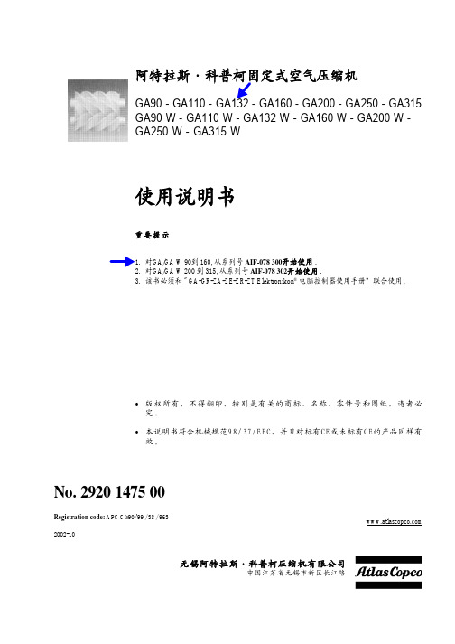
GA90 - GA110 - GA132 - GA160 - GA200 - GA250 - GA315 GA90 W - GA110 W - GA132 W - GA160 W - GA200 W GA250 W - GA315 W
使用说明书
重要提示
1. 对GA/GA W 90到 160, 从系列号 AIF-078 300开始使用 . 2. 对GA/GA W 200 到 315, 从系列号 AIF-078 302开始使用 . 3. 该书必须和 " GA-GR-ZA-ZE-ZR-ZT Elektronikon® 电脑控制器使用手册”联合使用。
1.3 Elektronikon® 控制系统 . . . . . . . . . . . . . . . . . . . . . . . 10 1.3.1 自动控制空压机 . . . . . . . . . . . . . . . . . . . . . . . 10 1.3.2 保护空压机 . . . . . . . . . . . . . . . . . . . . . . . . . . . 10 1.3.3 维修报警 . . . . . . . . . . . . . . . . . . . . . . . . . . . . . 10 1.3.4 断电后自动重新起动 . . . . . . . . . . . . . . . . . . . 11 1.3.5 允许起动 . . . . . . . . . . . . . . . . . . . . . . . . . . . . . 11
2 安 装 . . . . . . . . . . . . . . . . . . . . . . . . . . . . . . . . . . . . . . . . . . . 15 2.1 尺寸图 . . . . . . . . . . . . . . . . . . . . . . . . . . . . . . . . . . . . . 15 2.2 安装建议 . . . . . . . . . . . . . . . . . . . . . . . . . . . . . . . . . . . 21 2.3 电缆的规格 . . . . . . . . . . . . . . . . . . . . . . . . . . . . . . . . . 27 2.4 图标 . . . . . . . . . . . . . . . . . . . . . . . . . . . . . . . . . . . . . . . 28 2.5 冷却水的要求 . . . . . . . . . . . . . . . . . . . . . . . . . . . . . . 28 2.5.1 冷却系统的类型 . . . . . . . . . . . . . . . . . . . . . . . 28 2.5.2 冷却水的参数 . . . . . . . . . . . . . . . . . . . . . . . . . 29
845等线路图!.
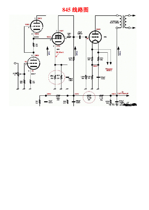
845线路图上图推动管45用2A3C代换天津全真电子管TJ Full music 45/n 网屏茄型价格:718.00元特征:是个茄形或圆顶型玻壳,四根镀金管脚的白陶瓷座,直热式氧化物阴极,网状板极、石墨板极三极管。
用途:用于音频放大器,输出功率达1.6W。
标准工作状态及参数:加热电压*……………………… 2.5V加热电流…………………………1.5A板极电压 (250V)栅极电压**………………………-50V板极电流…………………………34mA放大倍数…………………………3.5跨导………………………………3.9mA / V栅极电流…………………………0.05μA*交流灯丝供电或直流灯丝供电**交流灯丝供电栅极或板极回路与灯丝变压器次级的中心头相联,直流灯丝供电,栅极阳极的电源回路与灯丝负端相联。
平均特性曲线:如图表示板极电流,板极电压对应几组栅极电压特性曲线。
(交流灯丝电压供电)极限工作使用值:最大板极电压 (275V)最大板极功耗……………………10W上图为推动牛的制作!845牛两套,一套:交流高压是750V,中压是330V,负压70V,输出牛是8K/4欧、8欧;另外一套是:高压650V,中压165V,100V,输出牛也是8K的。
输出牛都有40瓦以上.大概的架构想用300B牛推845和2A3牛推845.推动牛参数:ZS-3045音频推动变压器(Drive transformers):本页更新于2009.9.22工艺特点(feature): 进口高纯度漆包线/约含10%坡莫合金(Permalloy)/法拉第屏蔽(Faraday Shield);匝数比(turns ratio):1:1.39;标称阻抗(impedance):一次侧(Pri)-3.5kΩ最大电流(Imax):一次侧(Pri)-170mA, 二次侧(Sec)-80mA;频响宽度(Frequency response):5Hz~101.2kHz -3dB,2A3在路测试(ICT)(In-circuit test);失真(THD):<0.1%(Output: 30Hz/2kΩ/0dB);幅度变化(amplitude change):20Hz ~ 20kHz 0dB ~ 0dB 2A3在路测试(In-circuit test);直流电阻(D.C.R):一次侧(Pri)138.9Ω, 二次侧(Sec);外形结构(Structure ):全密封(sealed);适应电路(to adapt the circuit):300B/2A3/等推动845/ГМ-70(GM70)/211/6C33C...绝缘强度(dielectric strength):≥1000V/1m(一次侧对二次侧、一次侧对铁芯)服务承诺(pledge):1. 本商品自发出之日起无人为损坏现象,一个月内包退换;2. 指标低于介绍的5%我们将双倍退还商品款。
(整理)图解47型万用表组装全过程.

说明:以下内容已经该录在光盘中,批量购买30台以上则赠送刻有本资料的光盘一张。
一般用户可以直接保存本文而不需要购买本光盘。
确实需要购买本文内容的光盘者(一般是互联网暂不到达的边远地区用),每张收费5元。
MF-47A印制板正面图万用表是一种多功能、多量程的便携式电工仪表,一般的万用表可以测量直流电流、交直流电压和电阻,有些万用表还可测量电容、功率、晶体管共射极直流放大系数hFE等。
MF47型万用表具有26个基本量程和电平、电容、电感、晶体管直流参数等7个附加参考量程,是一种量限多、分档细、灵敏度高、体形轻巧、性能稳定、过载保护可靠、读数清晰、使用方便的新型万用表。
万用表是电工必备的仪表之一,每个电气工作者都应该熟练掌握其工作原理及使用方法。
通过本次万用表的原理与安装实习,要求学生了解万用表的工作原理,掌握锡焊技术的工艺要领及万用表的使用与调试方法。
1 万用表原理与安装实习的目的与意义现代生活离不开电,我们电类和非电类专业的许多学生都有必要掌握一定的用电知识及电工操作技能。
通过实习要求学生学会使用一些常用的电工工具及仪表,比如尖嘴钳、剥线钳、万用表,并且要求学生掌握一些常用开关电器的使用方法及工作原理。
通过本次电工实习学生要接触到一定的电学知识,实现理论联系实际,认识一些常用电工器具的外形及结构特点,为后续课程的学习打下一定的基础。
电子与机械是密不可分的,在万用表的组装中还可以了解电子产品的机械结构、机械原理,这对将来的产品设计开发是非常有帮助的。
所以,五一电子科普加油站特向南京电子仪表厂专门订购了一系列的万用电表套件。
在个别地区,套件的价格可能会比非南京电表厂的成品表的价格还要高出几元或者十多元,但是,五一电子仍然强烈建议您选购本万用表套件!选购本万用表套件的理由:本万用表套件由南京电表厂生产,南京电表厂是国内最有名、历史最悠久、产品最值得信赖的电表厂之一;本万用表套件拥有最成熟的设计,不论在电路结构、机械结构还材料选材方面远远优于市面上常见的万用表;万用表是最常用的电工仪表之一,通过这次实习,学生应该在了解其基本工作原理的基础上学会安装、调试、使用,并学会排除一些万用表的常见故障。
梅兰 mge galaxy 7000安装手册
LDPE
04
聚丙烯
PP
05
聚苯乙烯
PS
06
守当 清 包 遵
地现行规定 除 装物。
报废处理
依据当 施耐德电气公司旗下 APC 公司将
地规定在产品使用寿命结束后处理产品。
它 集 清 这些报废 施耐德电气公司旗下 APC 公司将与其 公司合作,在产品使用寿命结束后收 并 除
产品。
产品
由 材料 产品 可回收
。
包装
提高废 效率及 便 包 拆 为
品处理
方 回收,请将 装物 开。
包 纸箱中含 % 上 再 纸板 所使用的 装
有 30 以 的 利用
。
包 大袋 袋由聚乙烯材料 装
与小
制成。
包 材料 带 识 装
可回收利用并 有相应标
。
材料
缩写
标识
编号
聚酯
TPE
01
高密度聚乙烯
HDPE
02
聚氯乙稀
VP C
03
低密度聚乙烯
- 温度剧烈变化,
-
真强放管含通菌电射酸道风、磁性热性不昆场水物气良虫平,或质,高、来或于体自产正外其生常寄它水环生垢热境虫源、下等的渣的…滓热放…等气射杂,质性水的平冷,却水,整流器与水接触的部分产生的电解腐蚀物质,
- 电池的使用状况。
wUPS 的安装须遵守以下标准的相关规定: wCEI 60364-4-42 标准:热效应保护。 wCEI 60364-4-41 标准:电击保护。 wCEI 60364-4-482 标准:建筑物电力系统安装。 w 在法国,须符合 NFC 15-100 标准。 wUPS 符合 CEI 62040-1-2 标准。
1.1 安装方法 ................................................................................................................................................ 10
笔记本电脑电池原理图
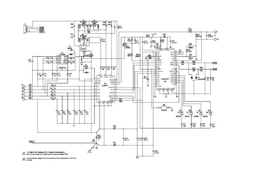
笔记本电池原理图MM1414,S-8254,BQ29311,BQ29312这四个是四节串联锂离子电池保护用的控制芯片.其它是电量计量芯片,也叫GAS GUAGE IC.它的主要功能是电量测量.此外它还检测电池的各种参数,如电压,电流,温度等,同时还包括与主机的通信,通过SMBUS 或单总线.寄存器中还存有其它信息,象制造厂信息,补偿参数,三级终止放电电压等等,有些参数是与电量测量相关的.有的芯片还提供二次保护控制.具体的情况你可以详细阅读一下数据手册,里面有详细说明.S-8244是针对3或4节串联锂离子电池的过充电保护控制芯片.它经常用于二次过充电保护控制上.输出常接一个受控温度FUSE,用于过充电保护.通常的过充电保护由一次保护电路完成,当一次保护电路失效后,二次保护电路可以动作,以避免电池被过充电而发生安全问题.它的保护是一次性的,保护动作后电池就无法使用.而基本的过充电保护是可恢复.注:电池最容易发生危险是被过充电时,因此才需要二次过充电保护.过放电只会使电芯损坏,却不会导致安全问题.什麽是一次保护电路與二次保护电路?一次保护电路是指基本的保护电路.它对锂离子电池起到过充电保护、过放电保护、过电流保护、短路保护的作用.此电路通常由锂离子电池保护IC配合两个充、放电开关的MOSFET来完成.在保护动作后,若符合恢复条件,电池就可恢复到正常状态,继续使用.二次保护是相对基本保护而言的,只是一种通俗的说话.它分好多种,前面提到S-8244就是用于二次过充电保护控制.它是在基本保护电路失效后来动作的,由于它常常是一次性的保护(比如控制温度FUSE,使它熔断),因此保护动作后电池就无法再使用了.是不是所谓的二次保护是由保险丝来完成的呢?不一定是保险丝,也有是控制电路的.象S-8244做的二次保护.有些电路好象很复杂.好象有二片充放管理芯片(除了MCU).TI的有个问题,为什么有些电路是管理和充放分开,如BQ2040 M1414 二个电路是独立的,但BQ2040可以控制笔记本对电池充电.所以有时会更换电芯后,机器能放电,但不能充,可你直接用一个外接电源却可充(因为这里不受BQ2040控制), 这种情况如何办? BQ2040外围的FLASH如何修改? 我也看到网上有软件,可都是些限制版,这种软件原理是什么?。
GA37+-90资料

用户利益
非常高的可靠性 最少的维护,降低了维护费用 比功机头:
– GA55+ -90 & GA75-90VSD: C146 (’03) – GA37+ -75 & GA37-55VSD: C111 (’05)
新的机头
带给客户的价值
– 确保在宽广工作范围和长时期使用的最佳性能
• 采用最佳的计算机技术优化的独一无二的转子型线 • 在一个宽的气量范围和压比范围内功耗最小
• 转子在整个生命周期中都有卓越的性能(当过滤器堵塞和压比增加), 这和转子在一个流量和压力下设计的 相比有着不同凡响的优势
– 可靠、省心
• 根据Six SIGMA 质量标准制造(受第三方认证) • 轴承的选择和齿轮的配置都是根据极端条件选择
– 智能控制
极端负载内置冷冻干燥机IFD
– 适用于46°C的环境标准 – 在最严酷的条件下都很可靠 – 节能模式 – 极好的露点
13
高效的油分离器
含油量<2ppm 优异的空气动力特性设计的容器
– 离心和重力分离效果强,减轻的分离滤芯的负 担
全新过滤器材料油气分离器滤芯
– 压降低 – 效率佳
GA37+ - 90
承诺您实现卓越生产力
1
GA 37+-90 kW
全新的设计
2
卓越的性能
型号 50Hz GA37+ 7.5 8 10 13 GA45+ 7.5 8 10 13 GA55 7.5 8 10 13 GA75 7.5 8 10 13 最高工作压力bar(e) P机组 7.5 8 10 13 7.5 8 10 13 7.5 8 10 13 7.5 8 10 13 FF机组 7.25 7.75 9.75 12.75 7.25 7.75 9.75 12.75 7.25 7.75 9.75 12.75 7.25 7.75 9.75 12.75 l/s 118 115 99 81 143 134 121 101 165 155 144 124 218 205 184 162 流量 FAD* m3/min 7.1 6.9 5.9 4.9 8.6 8 7.3 6.1 9.9 9.3 8.6 7.4 13.1 12.3 11 9.7 电机功 率 kw 37 37 37 37 45 45 45 45 55 55 55 55 75 75 75 75 噪音** dB(A) 65 65 65 65 66 66 66 66 69 69 69 69 73 73 73 73 重量(kg) P机组 1045 1045 1045 1045 1075 1075 1075 1075 1200 1200 1200 1200 1550 1550 1550 1550 FF机组 1165 1165 1165 1165 1195 1195 1195 1195 1360 1360 1360 1360 1700 1700 1700 1700
GAGMTSTR主板线路图
C81 1u/4/X5R/6.3V/K
VTT_OR
R137 57.6/4/1
GTLREF0
R138 100/4/1
C83 1u/4/X5R/6.3V/K
中間值0.9V
VTT_OR VTT_OL VTT_OR
VTT_OL
R108
62/4 -IERR
R124
62/4 -BR0
R152
62/4 -CPURST
5
4
3
2
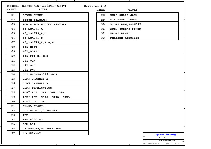
Revision 1.0 SHEET
TITLE
28 REAR AUDIO JACK 29 DISCRETE POWER 30 VCORE PWM_ISL6312 31 ATX, OTHERS POWER 32 FRONT PANEL 33 REALTEK RTL8111E
1 D
C
B
A
Gigabyte Technology
G23
B3 F5 A3
CPU-SK/775/S/GF
-HADS -BNR -HIT
-TBPP_RCI PU16 -DBSY -DRDY -HITM -IERR -HINIT -HLOCK -HTRDY
-TDPE_FCEPRU17
-HADS [8] -BNR [8] -HIT [8]
-BPRI [8] -DBSY [8] -DRDY [8] -HITM [8]
5
4
Model Name:GA-G41MT-S2PT
SHEET
TITLE
01 COVER SHEET
D
02 BLOCK DIAGRAM
03 BOM & PCB MODIFY HISTORY
04 P4_LGA775_A
珊星变频器说明书V2.7

本设备的用户和对使用本设备负有责任的人,必须详细阅读本手册,认真遵循手册中的 说明和指导,保证本设备的使用可靠和安全。在任何情况下,对于使用本设备不当而造成的 直接或间接的损害,本公司概不负责。 本手册中的图表仅用于对文字进行说明, 手册中所示的带插图的用途和用法本公司不承 担法律责任和义务。 未经我公司的许可,不得对本手册进行全部/部分,或其他方式的复制。 产品的使用或安装的不正确,会导致元件损坏和产品寿命缩短,用户在安装和使用变频 器的过程中,必须执行适用的工业标准和具体的安全指标规范,以及接口要求。
3.1.3 显示说明 ................................................................................................................24 3.1.4 操作说明 ................................................................................................................28 3.2 大面板键盘操作...........................................................................................................29 3.2.1 操作键盘 ................................................................................................................29 3.2.2 基本操作 ................................................................................................................30 3.2.3 监控方式切换 .........................................................................................................31 3.2.4 功能参数设置(编程模式) .......................................................................................33 3.3 参数设置注意事项 ........................................................................................................36 第四章 功能参数表 ................................................................................................................37 第五章 功能参数说明.............................................................................................................44 第六章 使用范例 ....................................................................................................................79 6.1 设定最大输出频率 ........................................................................................................79 6.2 由自控变为外控 ............................................................................................................80 6.3 低频时转矩提升 ............................................................................................................81 6.4 多段速运行....................................................................................................................81 6.5 加/减速时间的设定 .......................................................................................................83 6.6 点动运行 .......................................................................................................................84 6.7 用比例频率运行(主从操作)...........................................................................................85 6.8 过流、过压失速保护.....................................................................................................86 6.9 风机及水泵类负载的应用 .............................................................................................86 第七章 故障与排除 ..............................................................................................................88 7.1 故障诊断 .......................................................................................................................88 7.2 变频器复位....................................................................................................................90 7.3 故障排除 .......................................................................................................................91 第八章 维护与保养 ................................................................................................................92 8.1 日常检查 .......................................................................................................................92 8.2 定期检查 .......................................................................................................................92 8.3 部件更换 .......................................................................................................................92 第九章 技术规范 ....................................................................................................................93 第十章 串行通信 ....................................................................................................................96
阿特拉斯GA 系列ppt课件
lrtuieflntmloocvke
14 of 53
机械 – 电气
压缩机和电控柜分界清晰 易于理解的布局和方便的维护保养
Industrial Air Division Leaders in Innovation
15 of 53
布局清晰、大量的内部空间
Industrial Air Division Leaders in Innovation
GA30+ -75 ; GA37-45-55VSD
GA55+ -90 ; GA75-90VSD
Industrial Air Division Leaders in Innovation
2 of 53
为什么 – 目标
▪ 保持领先地位 ▪ 增加市场份额 ▪ 改善性能 ▪ 全新的坚固外观 ▪ 采用新的创新技术以获得卓越的可靠性 ▪ 提供防假冒的易耗件 ▪ 引进模块化设计技术
Industrial Air Division Leaders in Innovation
9 of 53
提升的性能
▪ GA 30+ -75 kW – 最多将比功率降低了8%,行业领先 – FAD 流量增加2%至6%,行业领先
▪ GA 37, 45, 55 kW VSD – 最多将比功率降低了8%,行业领先 – FAD 流量增加6%,行业领先
19 of 53
GA 30-90 kW 2005
层不出穷的内部技术创新...
Industrial Air Division Leaders in Innovation
20 of 53
创新
新型分离器滤芯
高效-免维护的齿 轮箱
整体化设计的 油过滤器
卸荷阀பைடு நூலகம்
亚特兰蒂斯科GA30+-90 GA37-110 VSD+油注射旋筒压缩机说明书

The ultimate smart solution,driven by efficiencyAtlas Copco’s GA compressors bring you outstandingsustainability, reliability and performance, while minimizingtotal cost of ownership. A choice of three premiumcompressor types (GA VSD+, GA+ and GA) provides you withthe compressed air solution that perfectly matches yourrequirements with clear value propositions. Built to performeven in the harshest environments, these compressors keepyour production running efficiently.4 Atlas Copco GA 30+-90/GA 37-110 VSD + oil-injected rotary screw compressors1071295Inlet filter• Heavy duty.• Maintenance every 4,000 hours.• Pressure drop indicator.4Interior Permanent Magnet (iPM) motor• Oil-cooled motor.• Optimal cooling for all speeds and ambient conditions.• Designed in-house in Belgium.• Oil-lubricated motor bearing: no (re)grease(ing), increased uptime.• IP66: pressure-tight.1New compressor element• New improved rotor profile.• Reduced pressure losses.• Optimized in and outlet portals.2Direct drive• Vertical design, less parts.• Oil-cooled, pressure-tight.• No gears or belts, no shaft seal.3Meeting and exceeding efficiency benchmarks:• The iPM motor of the GA 37L-110 VSD + exceeds IE5 standards.• Neos inverter and iPM motor exceed IES2 (EN 50598) requirements for power drive efficiency.IE5Electronic no-loss water drain• Ensures constant removal of condensate.• Manual integrated bypass foreffective condensate removal in case of power failure.• Integrated with compressor’s Elektronikon with warning/alarm features.5GA 37L-110 VSD +: Ultimate energy saverWhen you are looking for efficiency, lowest cost of ownership and sustainability, the GA 37L-110 VSD + delivers a superior solution. This oil-injected screw compressor with Variable Speed Drive technology generates energy savings of up to 50%. What is more, its upright, compact design saves valuable floor and workspace, eases maintenance access, and reduces total cost of ownership.Atlas Copco GA 30+-90/GA 37-110 VSD + oil-injected rotary screw compressors 5674131128105High-tech fan• Compact.• Low noise level.• High capacity for optimized cooling.• Compliant with ERP2020 efficiency standards.6Classic cooler design• Integrated water separation.• Separate oil/air cooler.• Easy access for maintenance.7Innovative Neos inverter• Atlas Copco’s in-house designed inverter also controls iPM motors.• IP5x protection.• Robust aluminum enclosure for trouble-free operation in the harshest conditions.• Fewer components: compact, simple and user-friendly.8Integrated dryer• Extra compact footprint.9Elektronikon Touch controller• High-tech controller with warning indications, compressor shut-downand maintenance scheduling.• Easy to use and designed to perform in the toughest conditions.• Standard SMART LINK remote monitoring to maximize air system performance and energy savings.• Optional multiple compressor control (2, 4 or 6 compressors).10Sentinel no-loss inlet valve• Optimizes the inlet flow of the air end.• No blow-off losses.• Full aluminum design: maintenance-free (GA 37L-75 VSD +).11VSD + Neos cubicle• Electrical components remain cool, enhancing their lifetime.• Dedicated drive for iPM technology motors.• Heat dissipation of inverter in separate compartment.126 Atlas Copco GA 30+-90/GA 37-110 VSD + oil-injected rotary screw compressors• Up to 50% energy savings with an extensive flow range (20-100%).• Integrated Elektronikon Touch controls the motor speed and high-efficiency frequency inverter. • No wasted idling times or blow-off losses during operation.• Compressor can start/stop under full system pressure without the need to unload.• Eliminates peak current penalty during start-up. • Minimizes system leakage due to a lower system pressure.• EMC compliance to directives (2014/30/EU).* Compared to fixed-speed compressors, based on measurement performed by an independent energy audit agency.Why Atlas Copco Variable Speed Drive +technology?Over 80% of a compressor’s lifecycle cost is taken up by the energy it consumes. Moreover, the generation of compressed air can account for more than 40% of a plant’s total electricity bill. To cut your energy costs, Atlas Copco pioneered Variable Speed Drive + (VSD +) technology in the compressed air industry. VSD + leads to major energy savings, while protecting the environment for future generations. Thanks to continual investments in this technology, Atlas Copco offers the widest range of integrated VSD + compressors on the market.VSD + for up to50% energy savings *Atlas Copco GA 30+-90/GA 37-110 VSD + oil-injected rotary screw compressors 7Up to 50% energy savingsAtlas Copco’s GA VSD + technology closelyfollows the air demand by automatically adjusting the motor speed. This results in up to 50% energy savings. In addition, lowered system pressure with GA VSD + dramatically minimizes energy use across your production.In almost every production environment, air demand fluctuates depending on differentfactors such as the time of the day, week or even month. Extensive measurements and studies of compressed air demand profiles show that many compressors have substantial variations in air demand.GA Fixed-Speed GA VSD+InvestmentEnergy Maintenance8 Atlas Copco GA 30+-90/GA 37-110 VSD +oil-injected rotary screw compressors126679Maintenance-free drive system• 100% maintenance-free; totally enclosed and protected against dirt and dust.• No coupling or slippage losses.• Standard up to 46˚C/115˚F; high ambient version 55˚C/131˚F.• Works reliably in harsh environments.1IE4/NEMA Super Premium Efficiency motors• IP55, insulation Class F, B rise.• Oil-lubricated drive side bearings.• Designed for continuous operation in harsh environments.2Robust spin-on oil filter• High efficiency; removes 300% smaller particles than a conventional filter.• Integrated bypass valve with the oil filter.• 8,000-hour service interval (GA 55+/GA 75+).3(Smart) no-loss drain• No-loss electronic drain on GA 30+-45+ monitors condensate build-up and removes liquid only when necessary to avoid air loss.• Smart no-loss water drain on GA 55+-75+ with automatic removal of condensate, auto-cleaning, and detection of potential issues.4-75The GA 30+-75+ is our fixed-speed oil-injected rotary screw compressor that sets the industry standard. It gives you more of the things that really matter: more energysavings, more air, and a longer lifetime. Its state-of-the-art compression element and a host of advanced features ensure maximum performance with best-in-class efficiency.+-75+).Atlas Copco GA 30+-90/GA 37-110 VSD + oil-injected rotary screw compressors 9Smart Temperature Control System (GA 55+/GA 75+)5Intelligent sensors (GA 55+/GA 75+)• Pressure drop sensors monitor the lifetime of the inlet filter, the oil separator, and the oil filter. • CAN cables allow for easy updates.6EQ2i• Multiple compressor control integrated as standard.8Heavy-duty air intake filter• Protects compressor components by removing 99.9% of dirt particles down to 3 microns.• 8,000-hour lifetime (GA 55+/GA 75+).9Elektronikon Touch for remote monitoring• High-tech controller with warning indications, compressor shut-down and maintenance scheduling.• Standard SMART LINK remote monitoring tomaximize air system performance and energy savings.7condensation.The smart unload algorithm monitorspressure fluctuations in real time to reduce the running time in unload and achieve maximum energy savings.43510 Atlas Copco GA 30+-90/GA 37-110 VSD + oil-injected rotary screw compressors1273564The GA 37-90 gives you that trusted Atlas Copco oil-injected screw performance at the lowest investment cost. Built with top-quality materials, the GA 37-90 ensures compressed air reliability and efficiency in the toughest conditions.Maintenance-free drive system• 100% maintenance-free; totally enclosed and protected against dirt and dust.• New state-of-the-art hybrid bearings extend the lifetime of the drive train by 33% (GA 55-90). • No coupling or slippage losses.• Standard up to 46˚C/115˚F and for high ambient version 55˚C/131˚F.1Super Premium Efficiency electrical motor• IE4 efficiency motor (GA 55-90).• IP55, insulation Class F, B rise.• Non-drive side bearing greased for life.• Oil-lubricated drive side bearings.• Designed for continuous operation in harsh environments.2Robust spin-on oil filter• High efficiency; removes 300% smaller particles than a conventional filter.• Integrated bypass valve with the oil filter.3Atlas Copco GA 30+-90/GA 37-110 VSD + oil-injected rotary screw compressors 118Oil cooler and aftercooler for tropical environments• Low element outlet temperatures, ensuring long oil lifetime.• Removal of nearly 100% of condensate by integrated mechanical separator.• No consumables.• Eliminates possibility of thermal shocks in coolers.4Advanced Elektronikon control & monitoring• Easy to use and designed to perform in the toughest conditions.• Monitoring features include warning indications, maintenance scheduling, and online visualization of machine conditions.• Standard SMART LINK remote monitoring to maximize air system performance and energy savings.5Heavy-duty air intake filter• Protects the compressor components by removing 99.9% of dirt particles down to 3 microns.• Differential inlet pressure for proactive maintenance while minimizing pressure drop.6Low noise fan• Silent operation.• High flows.• Compact design.7Integrated dryer• Excellence in air quality.• 50% reduction in energy consumption compared to traditional dryers.• Zero ozone depletion.• Incorporates optional UD+ filter according to Class 1.4.2.812 Atlas Copco GA 30+-90/GA 37-110 VSD + oil-injected rotary screw compressorsAs connected as you will beWhen it comes to connectivity, manufacturing equipment has long stayed behind. Not Atlas Copco. Our compressed air systems helped pave the way for Industry 4.0. We never stopped developing innovative features and introducing new options to help our customers meet their operational goals.SMART LINK• Real-time monitoring of your compressor’s operational parameters on your computer or mobile device. • Performance data and insights identify opportunities for optimization. • Service timeline.• Maintenance and service alerts.• Online resource center with manuals, documentation and technical information.Connect Elektronikon Touch(optional for GA 37/GA 45)The Elektronikon Touch features a 4.3-inch user-friendly, multilingual display with clearpictograms and a service indicator. The operating system offers a host of control and monitoring options and smart algorithms to optimize your compressor performance. Customized timers and efficiency controls are just a few examples.ControlAtlas Copco GA 30+-90/GA 37-110 VSD + oil-injected rotary screw compressors 13OPC UAAtlas Copco was the first compressor manufacturer to offer OPC UA, themachine-to-machine communication protocol that was developed especially for industrialautomation. That means you can integrate your Atlas Copco compressor seamlessly in your production network:• Standardization of production equipment communication.• Insight into production system performance and optimization options.• Network security thanks to various encryption levels, authentication, auditing, and user control to ensure security.Optimize Manage Equalizer 4.0Manage multiple compressors with the Equalizer 4.0 (integrated in your compressor or as a standalone unit):• Reduced pressure band: Create a narrow, predefined pressure band to save energy.• Optimal system performance: Program all compressors to have equal running hours to reduce service intervals.• Improve reliability and efficiency: With actionable performance reports, service warnings, and energy efficiency data.• Multiple compressor control: Manage up to 6 compressors in one air network. GA + units come as standard with a built-in EQ2i, allowing the control of a second compressor.14 Atlas Copco GA 30+-90/GA 37-110 VSD + oil-injected rotary screw compressorsIntegrated dry airUntreated compressed air contains moisture and aerosols that increase the risk of corrosion and compressed air system leaks. This can result in a damaged air system and contaminated end products. An air dryer is therefore essential to protect your systems and processes . The GA, GA + and GA VSD + compressors have an integrated dryer option to ensure your peace of mind.• Optimized sizing for the compressor, avoiding excessive energy consumption.• New oversized dryer option to ensure a low PDP in the toughest conditions (GA 55-90/ GA 55+-75+).• Fit for your application.• Controlled and monitored by the Elektronikon. • Space-saving all-in-one solution with low installation costs.Integrated purityThe optional UD+ filter and integrated refrigerant air dryer (IFD) efficiently remove moisture, aerosols and dirt particles to protect your investment. The UD+ filter has a 40% lower pressure drop than the conventional DD+/PD+ filter combination. It saves space and reduces energy costs. Using only 1 single filter it is possible to reach Quality Class 1.4.2 according to ISO 8573-1:2010.* The table values reflect the maximum limits according to the ISO quality air standard (ISO 8573-1:2010).** Water pressure dewpoint based on 100% RH at 20°C/68°F.Built-in quality airAtlas Copco GA 30+-90/GA 37-110 VSD + oil-injected rotary screw compressors All electrical energy used by a compressed air system is converted into heat. Why let that heat go to waste? A specifically developed energy recovery system can be built into your GA, GA +, and GA VSD +, allowing you to recover up to 75% of that power input as hot air or hot water (e.g.: changing room showers). Through efficient use of the recovered energy, you generate important energy cost savings and a high return on investment without compromising your compressor’s performance.Use yourcompressor twiceDuctingRecovered hot air can be used for:• Auxiliary or main heating of warehouses and workshops • Drying processesHot waterConvert compressor heat into hot water for:• Radiators• Laundries, industrial cleaning and sanitary facilities• Industrial process heating • Canteens and large kitchens• Food, chemical and pharmaceuticalindustriesAtlas Copco GA 30⁺-90/GA 37-90 VSD oil-injected rotary screw compressors 15Built-in energy recoveryOptimize your systemSome applications may need or may benefit from additional options and more refined control/air treatment systems. To meet these needs, Atlas Copco has developed options and easily integratedcompatible equipment.* FF units only.** Water-cooled units.*** Includes potential-free contacts: motor running, compressor load/unload. **** FF units limited to 50°C/122°F on some models.***** 55-75 kW only.- : Not available • : Optional16Atlas Copco GA 30+-90/GA 37-110 VSD+ oil-injected rotary screw compressorsAtlas Copco GA 30+-90/GA 37-110 VSD + oil-injected rotary screw compressors17Wet compressed air Intake air Condensate Air/oil mixture Dry compressed air OilCompressed air without free water Fixed-speed: GA +Fixed-speed: GAA B C D E F GIntake air Air/oil mixture OilHot compressed air CondensateCooled compressed air Dried compressed airA Intake airB Air/oil mixtureC OilD Hot compressed airE CondensateF Cooled compressed air GDried compressed air18 Atlas Copco GA 30+-90/GA 37-110 VSD + oil-injected rotary screw compressors*Unit performance measured according to ISO 1217, Annex C, Edition 4:2009.**A-weighted emission sound pressure level at the work station, Lp WSA (re 20 μPa) dB (with uncertainty 3 dB).Values determined according to noise level test code ISO 2151 and noise measurement standard ISO 9614.FAD is measured at the following working pressures:- 7.5 bar versions at 7 bar - 8.5 bar versions at 8 bar - 10 bar versions at 9.5 bar - 13 bar versions at 12.5 barReference conditions:- Absolute inlet pressure 1 bar (14.5 psi)- Intake air temperature 20°C/68°FPressure dewpoint of integrated refrigerant dryer at reference conditions:2ºC to 3ºC, 36°F to 37°FDimensionsHWDAtlas Copco GA 30+-90/GA 37-110 VSD + oil-injected rotary screw compressors 19* Unit performance measured according ISO 1217 ed. 4 2009, annex E, latest edition.**Mean noise level measured at a distance of 1 m at max. working pressure according toISO 2151: 2004 using ISO 9614/2 (sound intensity method); tolerance 3 dB(A).Technical specifications GA 37L-110 VSD +13 bar(e) (188 psig)20 Atlas Copco GA 30+-90/GA 37-110 VSD + oil-injected rotary screw compressors2935 0892 42 © 2022, A t l a s C o p c o A i r p o w e r N V , B e l g i u m . A l l r i g h t s r e s e r v e d . D e s i g n s a n d s p e c i fi c h a n g e w i t h o u t n o t i c e o r o b l i g a t i o n . R e a d a l l s a f e t y i n s t r u c t i o n s i n t h e。
佳能3018打印机培训手册

在各个图中,
表示机械驱动的路线,此时,图标上会伴有信号的名称。而箭头
则表示电气信号的方向。
“接通电源”一语指的是触发电源开关;关闭前门,或者关闭出纸单元的门等,其结果都是开始向本机器供电。
2. 在数字电路中,“1”表示一个给定信号的电压值为“高”;而“0”则表示“低”。(但是各个电路里的电压值是互不相
同的。) 此外,星号(*)(如“DRMD*”中的)表示的是 DRMD 信号在“0”时出现。
在几乎所有的情况下,一个微处理器的内部工作机制是无法在现场加以检查的,因此,对于本机器所使用的微处理器的工
作过程,本手册不予以讨论,而只对从传感器到 DC 控制板 PCB 的输入端,以及从 DC 控制板 PCB 的输出端到负荷的工
维护保养手册
LBP3010/3100/3150 系列 LBP3018
2008年3月3日
应用
本手册由佳能公司出版发行,用来向本产品的维修技术人员提供必要的信息,以便于那些符合条件的 人员学习有关本产品的技术理论、安装、维护和修理等方面的知识。本手册所提供的信息适用于本产品所 销售的所有地区,因此,它可能包含有不适合您所在地区的信息。