GE Pro1000
EFM32 电容式触控应用说明(AN0028)说明书

AN0028:低能耗传感器接口 — 电容感应该应用说明涵盖电容感应的基本要素,介绍了如何使用低能耗传感器接口 (LESENSE) 扫描多个电容式传感器,同时保持在 EM2 中,实现大约 1.5 µA 的电流消耗。
还可以穿过几毫米的塑料、玻璃或类似的非导电覆层运行。
该软件示例可简化电容式触控的 LESENSE 配置,同时实现最低的能耗。
它适用于 EFM32 Tiny Gecko 入门套件和 EFM32 Giant Gecko 入门套件。
该应用说明主要介绍如何通过 EFM32 Series 0 微控制器实施电容式触控。
对于电容式触控印刷电路板的硬件设计,请参见电容式触控硬件设计应用说明 (AN0040)。
为便于说明,本文档中会使用 EFM32 Gecko Series 0 来表示 EFM32 Wonder Gecko、Gecko、Giant Gecko、Leopard Gecko、Tiny Gecko、Zero Gecko 或 Happy Gecko MCU 系列。
内容要点•此应用说明包括:•本 PDF 文档•源文件 (zip)•示例 C-code•多个 IDE 项目1.介绍1.1 电容式感应电容式感应是目前广泛应用于各行各业的一项技术。
高性能电容式传感器能够准确地测量导体目标的邻近度、位置、湿度、液位或加速度。
低成本电容式触控传感器技术较为落后,通过测量用户手指在附近时的电容变化,主要用于人机界面。
这些类型的传感器在各类移动设备中越来越常见。
本应用说明将主要介绍在各类应用中用于用户交互的第二种传感器。
这些传感器的成本很低,较之机械开关具有多种优点,例如无活动部件,不容易因为时间、使用次数和环境变化而损坏。
EFM32 电容式触控功能主要用于以很低的能耗实施电容式触控按钮和滑块,但也适用于其他电容式感应应用。
带有低能耗传感器接口的 EFM32 设备可使用该外围设备扫描多个触摸板,并且仅在检测到触摸的情况下唤醒 CPU。
全球医疗三巨头介绍(GE、飞利浦、西门子)
通用电器公司公司简介通用电器公司GE是跨行业经营的科技、制造和服务型企业之一,在全球100多个国家开展业务,员工超过30万人。
涵盖6个业务部门:商务金融服务、消费者金融、工业、基础设施、医疗、NBC环球。
早在1906年,GE就开始发展同中国的贸易,是当时在中国最活跃、最具影响力的外国公司之一。
1908年,GE在沈阳建立了第一家灯泡厂。
1934年,GE买下了慎昌洋行,开始在中国提供电子设备的安装和维修服务。
1979年,GE与中华人民共和国重建贸易关系。
1991年,第一家合资企业GE航卫医疗系统有限公司在北京成立。
GE医疗(GEHealthcareTechnology)集团隶属于通用电器公司,在医学影像、信息技术、患者监护系统与医疗服务等领域提供广泛的服务。
GE超声是“买来主义”,95年之前是没有超声的。
先后买来日本横河公司、美国泰索尼公司挪威威曼公司(98年)和奥地利克雷兹公司(2001年)泰索尼:擅长腹部超声威曼:擅长心血管产品克雷兹:擅长三维成像合并后不断推出新产品,腹部、心脏、三维及便携彩腹部系列产品:LOGIQ9、"LOGIQ7、"LOGIQS6、"LOGIQP5、"LOGIQ5、"LOGIQ3心脏系列产品:VID(多维星)、VID4、"VID3维产品:Voluson730Expert、Voluson730Pro、VolusonE8便携彩超:LOGIQBook/e/i、VIDi/e、Volusoni产品特点:一流市场宣传,投入大,销售网络齐全。
产品线最全、最长,几乎涵盖了所有价位的产品。
产品性价比高,外观设计迎合国人审美习惯。
产品质量及稳定性较差,维修成本高。
LOGIQ3生产时间:2003年春季会推出产地:印度产品概况:腹部应用,分PRO和Expert两个版本市场表现:图像颗粒粗,故障率高(尤其探头)售后服务较差市场价格:35-50万之间,平均40万左右代理价:25万左右宣传技术术语及买点TruScan平台技术编码激励(CE)、编码谐波成像(CHI)、编码谐波血管造影(CHA)斑点噪声去除技术(SRI)有源面阵探头技术(主要是提高侧向分辨力)心脏方面:VID7应变和应变率显像、解剖M型(直线和曲线)、定量组织速度成像(QTVI)、组织追踪成像(Tissuetracking)灰阶血流(B-FLOW)原始数据存储系统自动优化(AO)自适应彩色增强技术(L3)最大分辨率血流(彩色多焦点技术)(L3)凸型扩展技术(L3)实时三维成像技术特点:腹部应用为主自适应彩色增强技术方向性能量图(仅一种)动态范围:30-120dB可视可调,每3dB一级VirtualConvex凸型扩展成像AO(组织自动优化)、7."ACE(彩色自动优化)、THI8.AnatomicalM-mode(解剖M型)9."Easy3D、Advanced3D(选项)技术参数:512通道10bit数字化动态聚焦120dB动态范围,30-120dB,每3dB可视可调实时三同步腹部探头10-90度扫描范围穿透深度:4-30cm640幅动态回放探头频带宽2-13MHz线密度:230频谱最大测量速度:PWD:8m/sCWD:15m/s频谱最小测量速度:2mm/s取样容积调节:1-16mm心脏解剖M型HD:40GMO:640MB、CD-RW标准配置:15寸彩色监视器两个探头接口(Expert为三个探头接口)B-Flow(Expert为标配)AO、ACE、THIAnatomicalM-modeVirtualConvexCD-RW、40G硬盘、MO、两个USB (只有一个可用做图像传输,另一个为软件升级专用)技术平台:延承LOGIQ系列的TruSCAN技术平台荷兰皇家飞利浦公司荷兰皇家飞利浦公司,于1891年在荷兰成立,是欧洲最大的电子公司之一。
GEX-1000操作说明书2010(最终版)
GEX-1000型数字式微机励磁装置使用说明书目 录1概况 (1)2功能说明 (1)2.1主回路 (2)2.2调节器控制单元 (2)2.2.1模拟量的采集 (2)2.2.2远方中控操作励磁装置信号输入(公共端为901:9) (3)2.2.3励磁装置工作状态及报警信号输出(公共端804:1) (3)2.2.4通讯 (3)2.2.5人机界面 (3)2.2.5.1键盘 (4)2.2.5.2LED指示灯 (4)2.2.5.3主画面显示 (4)2.2.5.4菜单操作使用说明 (5)2.2.5.5测量显示画面 (6)2.2.5.6参数设置菜单 (6)2.2.5.7功能选择菜单 (7)2.2.5.8开入状态菜单 (7)2.2.5.9传动试验菜单 (8)2.2.5.10故障追忆菜单 (8)2.2.5.11精度调整菜单 (9)2.2.5.12机组参数菜单 (9)2.2.5.13系统设置菜单 (9)2.2.5.14试验选项菜单 (10)2.2.5.15告警信息显示窗口 (11)2.3装置电源 (11)3运行操作 (11)3.1操作面板介绍 (11)3.2运行方式 (13)3.3增磁、减磁操作 (14)3.3.1增、减磁节点防粘连功能 (14)3.4故障后再投入 (14)3.5残压起励 (14)3.6正常开机步骤(就地) (14)3.7正常停机操作 (15)3.8故障报警及处理 (15)4设备维护 (16)4.1日常巡检内容 (16)4.2大小修内容 (17)5上位机监控 (17)5.1安装与启动 (17)5.2连接方式 (17)5.2.1单通道方式 (17)5.2.2双通道方式 (17)5.3系统设置 (18)5.4功能简介 (18)5.4.1主画面 (18)5.4.2状态显示 (19)5.4.3故障记录及SOE (20)5.4.4参数设置 (20)5.4.5波形分析 (21)5.4.6试验功能 (22)6中控设计指南 (22)7GEX-1000微机励磁调节器技术说明 (23)7.1装置特点 (23)7.1.1主要特点 (23)7.1.2适用范围 (24)7.1.3使用环境 (25)7.2主要功能及技术指标 (26)7.2.1主要功能 (26)7.2.1.1调节及控制功能 (26)7.2.1.2限制和保护功能 (26)7.2.1.3其它辅助功能 (26)7.2.2主要技术指标 (27)7.2.2.1模数转换器输入参数 (27)7.2.2.2开关量输入输出容量 (28)7.2.2.3输出参数 (28)7.2.2.4网络接口 (28)7.2.2.5电源参数 (28)7.2.2.6指标参数 (28)7.3原理介绍 (29)7.3.1主要原理 (29)7.3.2单板原理 (30)7.3.2.1电源系统和继电器输出板 (30)7.3.2.2计算机主板(CPU) (30)7.3.2.3模拟量采集板 (31)7.3.2.4脉冲放大板 (32)7.3.2.5显示面板 (32)7.4软件说明 (32)7.4.1主调度程序 (32)7.4.2中断程序 (33)7.5通讯协议 (37)8PSS试验方法及试验步骤 (40)1概况GEX-1000型微机励磁装置是北京科电亿恒电力技术有限公司GEX系列产品中主要应用于中小型同步发电机静止励磁系统的一型产品。
GE Sensing DPI 880 Druck多功能计ibrator DPI 880 产品说明书

Adjustable nudge output Provides small incremental output changes for accurately setting valve positioners, switches, trips, and alarms.
Automatic switch test Captures open/closed trip values providing a fast and highly accurate "safety system" check.
• Switch, trip and alarm verification
The DPI 800 Series is a complete range of advanced, robust and simple to use hand-held instruments. Highly cost effective, these tools are ideal for test/calibration of many popular process parameters. Advanced features and technical innovations address more applications in less time and deliver results you can rely on.
0 to 12.000 V
0.02% rdg + 2 counts
0 to 30.000 V
0.03% rdg + 2 counts
0 TO 4000.0 S
0.1 to 1.3 S
Switch detection
Open and closed, 2 mA current
科勒1000REOZM发电机组说明书 (中文)

o 50℃环境温度散热器为选配。
150℃温升 备用额定值 千瓦/千伏安 电流A
1020/1275 1534
910/1138 912/1140 844/1055
1728 1645 1464
928/1160 928/1160 932/1165
1762 1674 1616
水泵型式
620 (35282)
风扇直径(包括叶片),毫米(英寸) 风扇,kWm (HP)
1524 (60) 40 (53.5) 26.3 (32.2)
冷空气最大进气和排气阻力 散热器出口侧,千帕(英寸水柱)
0.125 (0.5)
运行要求
空气需要量
散热器冷却空气流量,米3/分(英尺3/ 分)~ 空气燃烧量,米3/分(英尺3/分)
标准功能和附件
其他标准功能
z 发电机保护(为装备Decision-MakerTM 550时的标准配置) z 电子调速器,等时 z 机油排放管 z 运行操作与安装手册 z 副励磁机和永磁发电机(PMG)
附件
开放式机组 排气消音器,医院型 排气消音器,严格型 不锈钢柔性排气接头
配备外罩的机组 隔音罩(带医院机型房屋顶安装的消音器) 防雨罩(带严格型机房屋顶安装的消音器)
冷却系统 机体加热器
[推荐用于20℃(68℉)以下环境温度] 城市水冷却 散热器接管法兰 远程散热器冷却
供油系统 供油软管 油、水分离器 燃油压力表 机底燃油箱带日用油箱
电气系统 蓄电池 蓄电池充电器,均充/浮充式 蓄电池加热器 蓄电池支架和电缆
维护与文献 一般保养文献包 修理包(包括空气、机油和燃油滤清器) 大修文献包 生产文献包
Igor Pro中文操作手册 - 1

i8chapteri2iigorpro概览iigorpro概览9概观11术语11关于概观11概观1常用部分11启动igorpro11输入数据11绘制图形13润饰图片13附加一个注释15附加一个标签15使用偏好16制作一个页面布局pagelayout17保存你的工作18载入数据18添加到图像20补偿轨迹trace20取消补偿轨迹trace20在图形中绘制21生成一个重新编辑宏macro窗口22重新编辑图片23保存你的工作23使用igor文档23图形化编辑数据24生成一个categoryplot可选的25categoryplot选项可选的26控制窗口commandwindow27浏览waves28使用数据浏览器databrowser29合成数据29缩放与平移30制作多个坐标轴的图片30保存你的工作31使用游标32删除轨迹与坐标轴32创建一个堆叠坐标轴的图形32index9添加一个页面布局34保存你的工作34创建控件controls34创建一个关联规则dependency36保存你的工作36常用部分结束37概观2数据分析37启动igorpro37创建合成数据37对高斯分布进行快速曲线拟合38多曲线的高斯拟合38数据排序39对数据子范围进行拟合39在拟合完成后进行拟合推算40添加一个拟合41概观3直方图和曲线拟合41启动igorpro41创建合成数据42白噪音的直方图histogram42高斯噪音的直方图histogram43直方图数据的曲线拟合43曲线拟合残差可选的45编程可选47保存程序文件可选49载入编程文件可选50进一步探索50index10概观本章节我们通过典型的操作逐步介绍igor的主要功能
Intel 千兆网卡PRO 1000是什么意思

经常有用户认为Intel PRO 1000是英特尔网卡的型号,实际上这个描述指的是Intel千兆速率的网卡,这一分类下包含很多型号,所以要如何选购一款合适千兆网卡首先要确认具体的型号。
Intel PRO 1000千兆网卡主要有5个系列:Intel PRO 1000 PT、Intel PRO 1000 MT、Intel PRO 1000PF、Intel PRO 1000 MF、Ibtel PRO1000GT用的较多的是Intel PRO1000 PT系列,尤其是IntelPRO/1000 PT Dual PortServer Adapter这款,这个描述对应的型号叫做EXPI9402PT,是英特尔一款千兆PCI-E双口网卡,对应接口类型为RJ-45,可用在PCI-E X4,X8,X16插槽上。
这款千兆双电口网卡的价格大约在八百左右是目前机器视觉和工控机行业首选的一个型号。
此外这个系列中还有一款四口千兆网卡,描述为Intel® PRO/1000 PTQuad Port Low Profile ServerAdapter,这个描述对应的型号叫做EXPI9404PTL,是Intel千兆网卡中比较早期的一款千兆四口网卡,对应接口类型同样为RJ-45,可用在PCI-E X4,X8,X16插槽上,价格大约在2千左右,在千兆PCI-E四口网卡的型号里是性价比较高的一款。
Intel PRO 1000 PF和Intel PRO 1000 MF这2个系列是千兆光纤网卡,由于成本相对较高,用的客户相对也较少,其中Intel PRO 1000 PF千兆网卡是PCI-E接口的,Intel PRO 1000 MF是PCI接口的。
价格在一千五到两千五百元左右。
以上就是Intel PRO 1000千兆网卡的一些相关信,息更多技术参数和报价信息信息用户可咨询intel网卡分销中心华天易达科技有限公司,可提供更专业更合适的网卡选购方案。
Monster Power Center Pro 1000说明书
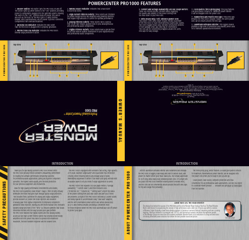
S A F E T Y P R E C A U T I O N SWith its aluminum extruded exterior and rubberized ABS endcaps the PRO 1000 is rugged, road-ready and built to deliver clean, safe power no matter where your music takes you. You’ll really appreciate its 10-ft long, extra heavy duty, shielded power cord—it’s length lets you place the PRO 1000 wherever shared power is needed most, and the cord can be conveniently wound around the unit’s end caps for trip-and tangle-free portability.The three-prong plug, which features 24-karat gold-plated contacts for maximum, instantaneous power transfer, can be snapped onto the power cord when you’re ready to pick up and go.Clean power, clean sound, complete protection and totalconvenience for all professional audio applications. Just like you expect in a Monster Power product . . . because you get more of everything from the Monster.P O W E R C E N T E R P R O 1000P O W E R C E N T E R P R O 1000A B O U T P O W E R C E N T E R P R O 1000INTRODUCTIONPOWERCENTER PRO 1000 FEATURES1. ON/OFF Switch: This switch turns the PRO 1000 on and off. The switch lights up when turned to the “ON” position, providing power to components plugged into the switched outlets. Pressing the switch to the “OFF” position shuts off power. This switch also acts as the reset for the PRO 1000’s 15-amp thermalbreaker, which automatically cuts off power to protect connected components from overload situations.2. GROUND OK Indicator: Indicates the wall outlet that the PRO 1000 is plugged into is properly grounded.3. PROTECTION ON Indicator: Indicates the PRO 1000’s internal surge protection is active.4. WIRING FAULT Indicator: Indicates that a wall outlet is incorrectly wired.5. High Current Filtered Outlets: These outlets are intended for power-hungry devices like amplifiers and powered monitors that require high amounts of current for optimal performance.6. Analog Filtered Outlets: These outlets have a special filter circuit that reduces audible noise in your analog musical and professional audio components.7. Digital Filtered Outlets: These outlets have a special filter circuit that reduces audible interference in your digital musical and professional audio components.8. Current and Voltage Availability LED Bar Graph Meters: These LED meters provide constant status regarding the quality and stability of the power coming from the wall outlet to your PRO 1000. 9. Extra heavy duty, 10ft. shielded power cord: This power cord’s extra length enables flexible placement of the PRO 1000 to reach inconveniently located wall outlets. The cord’s rugged heavy duty, shielded construction protects it from damage while also rejecting RF interference. The cord can be conveniently wrapped around the unit’s end caps for easy storage.10. Gold-plated, three-prong plug: This plug features 24k gold-plated contacts for maximum power transfer. It can be snapped onto the power cord.11. Rubberized ABS-Plastic End Caps: These end caps enhance the PRO 1000’s durable chassis. The unit’s power cord can be wound around the end caps.12. Aluminum Extruded Exterior: This rugged chassis provides a high level of protection and stability when used in its intended operational environment.®INTRODUCTIONThank you for purchasing Monster’s PRO 1000 PowerCenter. The PRO 1000 proudly reflects Monster’s unwavering commitment to creating the ultimate performance-enhancing solutionsfor professional audio applications, giving you superior component operation, the highest audio quality, and the best protection for your precious equipment and instruments.Ideal for high quality performance environments and studios,the PRO 1000’s patented Clean Power ™ Stage 2 filter circuitry virtually eliminates the noise that goes right through typical surge protectors. Two isolated filters, optimized for analog and digital equipment, provide excellent AC power line noise rejection and isolation of analog gear from digital components for improved component-generated noise rejection, leaving you with more natural tone, increased dynamic range and none of the “dirty” AC-induced gremlins that would otherwise interfere with the way you and your gear perform.The PRO 1000 features four digital outlets and two analog outlets, as well as two high-current filtered outlets that provide power-hungry amplifiers with the power they need to operate with maximum headroom, the best transient response and the clearest tone.The PRO 1000 is equipped with Monster’s fast acting, high-capacity 2775 Joule, Multiple SurgeGuard ™ and Dual-Mode Plus Protection Circuitry, which instantly detects any voltage surge or spike,immediately suppresses it before it can reach your gear, and will emit an audible alarm to let you know if surge suppression occurred.The PRO 1000’s two separate LED bar graph meters (“Voltage Availability,” “Current Draw”) and three indicator LEDs(“Protection On,” “Ground OK,” “Wiring Fault”) report the status of the power coming from your wall outlet and alert you if there are problems. All eight of the PRO 1000’s switched AC power outlets are widely spaced to accommodate bulky “wall wart”adapters, and the unit’s illuminated power switch also serves double duty as a 15-amp thermal breaker, providing a convenient resetfor those instances where the PRO 1000 automatically cuts off power to protect your gear.About Noel Lee, The Head MonsterThe driving force behind the success of the PRO 1000 and the entire Monster Power family is Noel Lee, The Head Monster. Noel is best known for popularizing the concept of high performance audio cable over 20 years ago with his creation of Monster Cable. Originally a laser-fusion design engineer at Lawrence Livermore National Laboratory and later a touring musician, Noel has invented or co-invented over 125 U.S. and international patents and drives the explosive growth of The Monster Group into more than 80 countries worldwide. Monster Power is his realization of a long-nurtured vision of making affordable power solutions that deliver the best possible sound and picture.The Head MonsterTop View1257643211198Top View1257643211198I N S T R U C T I O N SI N S T R U C T I O N SHOOK-UP GUIDEP R O B L E M S A N D S O L U T I O N S-PLEASE READ AND OBSERVE THE FOLLOWING SAFETY POINTS AT ALL TIMES• Analog Filtered OutletsMost analog components, like foot pedals and tube preamps, create audible noise that can easily interfere with your signal. These two outlets have a special filter circuit that reduces audible noise in your analog musical and professional audio components.I N S T R U C T I O N SHOOK-UP GUIDEHOOK-UP GUIDEI N S T R U C T I O N SI N S T R U C T I O N SPROBLEM – The PRO 1000 is not receiving power.Possible Cause #1The PRO 1000 is not turned on.Possible Solutions• Press the PRO 1000 switch into the “ON” position.• Make sure the PRO 1000’s AC power plug is plugged into a properly grounded 120V wall outlet.• In some venues or studios a wall switch may need to be thrown to make the wall outlet come alive. Try turning on the light switches located near the wall outlet that should be powering the PRO 1000.Possible Cause #2Too many devices are connected, causing an overload, throwingthe Thermal Circuit Breaker. Please note: The total power consumption on all the components powered by the PRO 1000 should not exceed 1800 watts.Possible Solutions• Press the PRO 1000’s combination ON/Off/Thermal Circuit Breaker switch into reset. Please allow 10 minutes from the timethe Circuit Breaker is initially thrown before attempting to reset. If you reset too soon, the breaker will prematurely sense power overload and not allow the unit to operate.Possible Cause #3The PRO 1000 power cord is plugged into an outlet on the back of one of your components and the component is not turned on.Possible Solutions• Turn the component power on.NOTE: For the best possible performance, plug the PRO 1000 into a wall outlet, not an outlet on another component.PROBLEM – The PRO 1000 is not providing power to the other components.Possible Cause #1The component is plugged into a switched outlet and the PRO 1000 has not been turned on.Possible Solutions• Turn the PRO 1000 on.Possible Cause #2PRO 1000 is plugged into a switched outlet on a component that is not turned on.Possible Solution• Turn on the component.NOTE: For best possible performance, plug the PRO 1000 into a wall outlet, not an outlet on another component.PROBLEM – Speakers, monitors or headphones emit a humming or buzzing noise.Possible CauseThe PRO 1000 is sharing AC power with equipment that is not properly grounded.Possible Solution• Connect your PRO 1000 to a dedicated outlet.• High Current Filtered OutletsThese outlets are intended for power-hungry amplifiers, powered subwoofers and other similar devices that require high amounts of current for optimal performance. Other components will function as intended if connected to these outlets, but devices requiring high current will operate best when plugged into these outlets.• Digital Filtered OutletsWhile digital components like multi-effect units and computers don’t generate the noises you might associate with analog equipment, their reliance upon clock frequencies and their vulnerability to different bands of noise can create equally problematic interference for your signal. These digital filtered outlets have a special filter circuit that reduces audible interference in your digital musical and professional audio components.TROUBLESHOOTINGANALOG EFFECT PEDALPOWERCENTER PRO 1000AMPLIFIERDIGITAL SIGNAL PROCESSOROutlet Hook-upBecause certain components don’t need continuous power, or shouldn’t be powered continuously, all of the PRO 1000’s outlets are “switched.” This means the components you plug into the PRO 1000 won’t receive power until your unit is turned on.The PRO 1000’s outlets are grouped into three different sections according to specific filter circuitry that is used to eliminate noise and optimize performance for particular types of components. When connecting your gear to the PRO 1000, please select an outlet within the group whose label most closely reflects the type of component you want to use. The diagram below shows one possible set of power connections, using the different filters for maximum benefit.EXAMPLE:WARNING – Power SourcesDo not plug your Monster POWERCENTER into a power outlet that differs from the source indicated for safe use on the Monster POWERCENTER. If you don’t know the type of electrical power that is supplied to your home, please consult your local power company.WARNING – Grounding and PolarizationA. Your Monster POWERCENTER has a three-wire grounding-type AC plug (a three-prong plug). This plug is designed to be inserted into a grounding-type outlet only. If this plug doesn’t fit directly into your outlet, do not attempt to force it into the outlet. Instead, reverse the plug and reinsert it. If this doesn’t work, contact a local electrician to install the proper polarized outlet. Never attempt to dismantle the plug in any way (or to alter an extension cord) to make it fit into a two-prong outlet. Do not attempt to defeat the grounding feature by using a 3-to-2-prong adapter. Instead, call a local electrician to install a properly grounded outlet.B. If you use rooftop devices such as satellite dishes, antennas, or any other component with wire that connects to your Monster POWERCENTER, be sure the wire(s) is properly grounded. This protects against voltage surges and static charges. Do not place any part of an antenna near overhead power lines, or any other power circuit. Do not touch any power line or power circuit. Doing so may cause you severe physical injury and possibly result in death.WARNING – Storm PrecautionsIn the event of a lightning storm, immediately disconnect your Monster POWERCENTER from its power source. After you’ve done this, it’s not necessary to disconnect any components from your Monster POWERCENTER.WARNING – No User Serviceable Parts InsideIf, for any reason, your Monster POWERCENTER is not operating properly, do not remove any part of the unit (cover, etc.) for repair. Unplug the unit and consult this owner ’s manual for warranty and service information.WARNING – Exposure To HeatDo not expose your Monster POWERCENTER to direct sunlight or place it near wall heaters, space heaters, or any enclosed space prone to temperature increase (e.g., car).WARNING – Liquid: Avoiding Electrical ShocksDo not operate your Monster POWERCENTER if liquid of any kind is spilled onto or inside the unit. Do not operate your Monster POWERCENTER near rain or water that’s spilled or openly exposed (e.g., kitchen or bathroom sink).WARNING – Power Cord SafetyA. When routing your Monster POWERCENTER AC power cord, do not place it nearheavy foot traffic areas (e.g., hallways, doorways, and kitchen floors). Do not create a trip hazard with the power cord.B. If your power cord’s protective jacket begins to rip or fray, exposing the internal wiring, shielding, etc., disconnect it from the power source and discontinue use of the Monster POWERCENTER immediately. Please see warranty information.WARNING – Proper CleaningIn general, the only cleaning necessary for your Monster POWERCENTER is a light dusting. Unplug your component from the wall socket before cleaning it. Do not use any type of liquid or aerosol cleaners.WARNING – Medical ConditionsThe Monster POWERCENTER is not designed for use with any medical equipment.。
Gavita Pro 1000e DE US 208-240 SL安装和使用说明书

line1 IntroductionThank you for purchasing the Gavita Pro 1000e DE US 208-240 SL. This manual describes the mounting and installing of the product and also describes how to use the product. Please read and understand this manual completely before using the product. Only use the product as specified in this manual.1.1 Used SymbolsWarning! A warning indicates severe damage to the user and/or product may occur when a procedure is not carried out as described.Caution! A caution sign indicates problems may occur if a procedure is not carried out as described. It may also serve as a reminder to the user.N ote: A note gives additional information, e.g. fo r a procedure.This symbol indicates that the reflector and lamp can reach very high temperatures (>85 °Celsius / >185 °Fahrenheit). Observe a cool down period before performing maintenance.This symbol is an internationally recognized symbol used to designate recyclable materials.This symbol is a certification mark employed on electronic products manufactured or sold in the United States which certifies that the electromagnetic interference from the device is under limits approved by the Federal Communications Commission.This symbol shows that a product has been independently tested and certified to meet recognized standards for safety. The symbol on the material, accessories or packaging indicates that this product may not be discarded as household waste. By disposing of the equipment in the proper way, you will be helping to prevent possible risks to the environment and public health, which might otherwise be caused by improper handling of the discarded equipment. Recycling of materials contributes to the conservation of natural resources. Therefore, please do not dispose of your old electronics and electrical appliances via household waste.T his symbol indicates the minimum distance (B) between the fixture (A) and the lit surface. 2 Product descriptionThe Gavita Pro 1000e DE US 208-240 SL is an adjustable horticultural fixture. The Gavita Pro 1000e DE US 208-240 SL can beused to drive a double ended 1000 W 400 V high frequency (electronic) high pressure sodium lamp.The Gavita Pro 1000e DE US 208-240 SL is an e-series product. It can be remotely switched and adjusted by a Gavita Master controller. The controller can automatically switch the fixture on and off during a 24 hour cycle.The controller also offers a temperature safety feature: auto-dimming or switching off connected fixtures when the temperature in a climate room becomes too high.The product can also be controlled by conventional timers in combination with a contactor. Make sure the dummy RJ plug sits in the IN port. If not, the fixture will not operate.In this manual, the Gavita Pro 1000eDE US 208-240 SL will be referred to as: “the fixture”.1000eDE US 208-240 SL3 Product information and specifications3.1 General product informationProduct name Pro 1000e DE US 208-240 SLManufacturer Gavita International bvEAN Code8718403054422Part number18.30.14.24.20Plug type Nema 6-153.2 Technical specificationsProduct weight8.4 lbs (3.8 kg)Dimensions (L*W*H)22.2”x9.7”x7.8” (56,5x24.5x19.5cm) (height excl. mounting hooks)Temperature case< 70 °Celsius / 158 °FahrenheitTemperature ambient0 ~ 35 °Celsius / 32 ~ 95 °FahrenheitInput voltage +/-10%208 V AC240 V ACInput current at 100% 5.2 A 4.5 AInput current at 115% 5.9 A 5.1 AMax current 6.8 AInput power at 100%1000 WInput power at 115%1236 WApparent power +/- 3%1082 VAPower factor0.97 - 0.99Relative humidity< 70% (not condensating)Total Harmonic Distortion< 10%Frequency50 - 60 HzCertification c CSA usInsulation Class 1 - requires an earth connectionPower inlet IEC C14Power output settings50 - 115%External control signal:RJ connector built in (6P6C)Ignition voltage: 5 kV / 600 msInrush current:≤ 40 AmpsInrush duration:1,6msEarth leakage current:≤ 1 mA3.3 Compatible products and accessoriesProduct name Gavita part numberCompatible controllers Gavita EL1 Master controller41.00.12.20 Gavita EL2 Master controller 41.00.13.20Replacement reflector Gavita HR96 DE30.46.13.00 Gavita MD 135 DE HC30.07.13.00 Gavita W 150 DE31.26.13.00Compatible lamps Gavita Pro Plus 1000 W EL DE HPS26.10.16.12 Compatible power cord Power cord US 240 V, 2.5 meter / 8.2 ft44.30.41.10 Compatible interconnect cable Interconnect cable RJ43.50.00.17Repeater bus connection kit43.50.10.003.4 EnvironmentThe product is intended to be used in greenhouses and climate rooms. The product can be used in damp environments. The product may not be used in wet environments or outdoors. The lamps function optimally when the ambient temperature is between 20 ~ 30°C / 68 ~ 86° Fahrenheit.3.5 LegalThis device complies with Part 18 of the FCC Rules.CSA approved.4 Safety recommendations and warningsWarning! Carefully read the warnings below before using or working with the product!• Always adhere to the local rules and regulations when installing or using the fixture.• Do not open or disassemble the fixture, it contains no servicable parts inside. Opening the fixture can be dangerous and will void the warranty.• This product may cause interference to radio equipment and should not be installed near maritime safety communications equipment or other critical navigation or communication equipment operating between 0.45 - 30 MHz.• Do not use the fixture when either its lamp or its power cord are damaged. Replace the power cord only with originalcertified cords. Replace the lamp only with lamps specified by Gavita (see paragraph 3.3).• The use of other lamps may damage the product and lamp and will void the warranty.• Modifications to the cords can lead to unwanted electromagnetic effects, which makes the product not comply with legal requirements.• Do not expose the fixture to:-condensing humidity, heavy mist, fog or direct spray;-(ambient) temperatures outside the specified range;-dust and contamination;-direct sunlight during use or HID light that could heat up the ballast.• Always disconnect the fixture from mains before performing any maintenance.• Always allow for a cool down period of at least 30 minutes before touching the lamp or reflector. Touching the lamp or the reflector when the lamp is lit or immediately afterwards will result in severe burns!• Never touch the lamp with bare hands as this will cause damage to the lamp.• Do not use the fixture near flammable, explosive or reactive substances. The lamp and the reflector of the fixture reach temperatures of >85 °Celsius / 185 °Fahrenheit.• Do not use sulfur vaporizers or water misters. Sulfur and calcium deposits on your reflector will decrease its efficiency.• The installation and use of the fixture is the responsibility of the end user. Incorrect use or installation can lead to failure and damage to the fixture. Damage to the fixture and electronic circuitry as a result of incorrect installation and use revokes the warranty.5 Contents (1)A. Pro 1000e DE US 208-240 SL fixture1. Electronic ballast2. Pro-line bracket3. Lever to unlatch reflector4. Lamp sockets5. Reflector Gavita HR96 DE*6. Mounting points*The reflector is delivery dependent,it may differ from the imageB. Gavita Pro 1000 W EL 400 V lampC. Interconnect cable (RJ/RJ )Cable length: 2.5 m / 8 ftD. Power cord with NEMA 6-15 plugE. Dummy6 Controls, connections andindications (2)A. IEC C14 connectionB. Gavita 2xRJ connector1. RJ IN2. RJ OUTC. Status LED7 InstallationW arning! Avoid coiled cords. Coiled cords may lead to electromagnetic interference.W arning! Always install the lamp before connecting the fixture to the mains.W arning! When connecting the fixture to the controller it may ignite. Make sure either power is disconnected or the controller is switched off.W arning! Ensure the local cabling can support the voltage and current requirements of the fixture.7.1 Preparing the fixture for use• Switch off mains power.• Install the lamp in the fixture (see paragraph 10.1).• Hang the lamp by its two mounting points (3). The mountingspoint are spaced 407 mm / 16 inches apart.1.2. Gavita 2xRJ NEMA6-157.2 Repeater bus connection kit (optional)The repeater bus connection kit contains the following items:1. 2 x EMC ferrite snap-on black bag (13x12x5x25.5x2.4)2. 4 x Gavita splitter 1 to 2 6P6C grey RJ25 (in bag)3. 8 x grey modular jack interconnect cable 6P6C RJ25 (in bag)4. 8 x SNAP-ON ferrite grey (in bag)5. Interconnect cable 6p 82 ft (25mtr) grey (in bag)7.3 Preparation for use with a controllerUsing a daisy chain setup, a maximum of 100 fixtures can be connected to one controller. Up to 500 fixtures per daisy chain can be connected when using splitters. See section 7.4 and 7.5 of this manual and the manual of the controller.• Take the unstripped black interconnect cable.• Cut the cable (supplied with controller) to the desired length and strip both ends using a crimp tool (5).• Insert the cable end in the RJ14 connectors (6) and use the crimp tool to finish the assembly.7.5 Connecting up to 500 or 1000 fixturesUsing a setup with daisy chained splitters, up to 500 fixtures on EL1 and 1000 fixtures on EL2 (over two channels) can be connected as shown in fig. 10.• Use the black controller cable (item comes with the controller) to connect the primary channel of the controller to the input port of the first splitter (10A).• Remove the dummy from the input port of the fixtures (8).N ote: Keep the dummy in a safe place! The dummy is necessary to operate the fixture in standalone mode.• Use a grey 6PC6 modular jack interconnect cable (item 3.) to connect the output port of the splitter to the input port of the first fixture (10C).• Use a grey 6PC6 modular jack interconnect cable (item 3.) to connect the output port of the first fixture to the input port of the second (10D).• Repeat these steps to connect up to 100 fixtures per splitter output port (10E). Up to 500 fixtures can be connected to the primary channel.• Snap-on two grey ferrite cores (item 4.) on the grey interconnect cable (item 3.) close to the 6P6C plugs.• Use the grey 6PC6 modular jack interconnect cables (item 3.) to connect the outport of a splitter to the inport of the next (10B).• Use the black secondary channel (item comes with controller) (10G) to connect another 500 fixtures, in the same way the fixtures are connected to the primary channel.Warning! Ensure the power cord and the controller cables do not touch any of the reflectors.Warning! Distribute number of fixtures evenly over daisy chains.Warning! Ensure the repeater bus connections are integrated in a correctly set up installation for best results.Warning! Boosters should never be used to expand.Warning! The maximum cable length per splitter is 250m (100 interconnect cables).7.6 Connecting the fixture to the mainsWarning! Ensure the cord is not coiled and does not touch any hot surfaces.W arning! If external switching gear is used to switch the fixture, ensure it can cope with the inrush current of the fixture (see paragraph 3.2). Always use a double pole contactor suitable of switching a capacitive load. Never use householdtimers to switch the fixture!• If a controller is used, ensure the controller is connected to the fixture.• Plug the power cord into the mains.• Switch on mains power.8 Product useWarning! Never use the fixture without a lamp or reflector!C aution! Before you dim or boost your HPS lamp, make sure that you run it at nominal value (100%) for at least 100 hoursto stabilize the lamp. Failing to do so may lead to sub-optimal light levels and premature end of life failure of your lamp.8.1 Using the controller to adjust the output of the lampThe output of the lamp is steplessly variable from 50-115% when connected to a controller. Consult the controller manual for more information on controlling the output of the lamp.9 Troubleshooting using the status LEDThe multi colour status LED provides information on the condition of the controller and the lamp. Consult table 1 and 2 to interpret the status LED. LED signals are represented by colored dots.- All operating modes include GREEN;- All warning codes include RED;- All history codes (except the ignition code) include ORANGE;- WARNINGS and history codes overrule operating mode display.9.1 Status indicationsStatus LED message Status fixture Description Action / SolutionNo power / off The fixture is not connected to themains or the power is off Check powerBallast stand-by Fixture is connected to the mains and to a controller. Output of ballast is offBallast on Fixture is connected to the mains and to a controller. Output of ballast is onFixture is ignitingthe lamp Fixture is trying to restart the lamp No action required. When lamp doesn’t start: Lamp too hot, defect or not properly connected (remote). Disconnect, check power cord and connections9.2 Error or warning indicationsStatus LED message Status fixture Description Action / Solution Too low voltage Input voltage is too low Check mains voltageToo low voltageoccured in past See above, resetToo high voltage Input voltage is too high Check input voltage, check wiring and connection, check neutral in 3 phase systemsToo high voltageoccured in past See above, resetToo hightemperatureElectronics temperature is too high(max. 115 °Celsius / 239 °Fahrenheit)Disconnect from mains. Checkinstallation, clean ballast, checkenvironment temperature(max 35 °Celsius / 95 °Fahrenheit). Makesure fixture is not heated by HPS lamplight. Wait untill the lamp is cooled down,then reconnect to mainsToo hightemperatureoccured in pastSee above, resetNo signal fromcontrollerFixture is connected to the mains andset to EXT but there is no signal on thecontrol input.If a controller is connected, search forloose connections, defect contacts orshort-circuits.Table 1 Table 210 Inspection, maintenance and repairW arning! Disconnect the product from mains before performing anymaintenance or repairs.W arning! Do not open or disassemble the fixture, it contains no servicable partsinside. Opening the fixture can be dangerous and will void the warranty.W arning! Always allow for a cool down period of at least 30 minutes beforetouching the lamp or reflector.C aution! Do not clean the fixture with detergents, abrasives or other agressivesubstances.C aution! Do not touch the inside of the reflector during installation and do notuse water, abrasives or detergents to clean it. This will damage the reflectivesurface.•Contamination may couse overheating and decreased performance.-Clean the inside of the reflector only with a soft, dry cloth;-cloth.•damaged lamp.N ote:when the lamp runs on full power. If not, replace the lamp.• Regularly check the wiring of the product to ensure it is undamaged.10.1 P lacement and replacement of the lampWtouching the lamp or reflector.CAlways use a fabric glove to handle the lamp.C aution! Only use lamps specified by Gavita (see paragraph 3.3).N ote:whichever one comes first.• Switch off mains power.•if the lamp is damaged.• Open the lamp holders by sliding them outwards (11).• Carefully take the lamp out of the fixture (12).••springs hold the lamp (13).• Close the lamp holders by sliding them inwards (14).• Switch on mains power.10.2 P lacement and replacement of the reflectorW arning! Always allow for a cool down period of at least 30 minutes beforetouching the lamp or reflector.N ote: Gavita recommends replacing the reflector* after 5000 lighting hours.Depending on the environment and contamination levels the reflector will degrade.The Vega/Miro™ aluminum can not be cleaned without damage. Therefore werecommend to change the reflector once every year. Also replace the lamp whenreplacing the reflector.* The reflector is delivery dependent, it may differ from the image.• Switch off mains power.• Remove the lamp from the fixture (see paragraph 10.1).• Support the reflector on the side of the reflector lever to prevent it from falling(15).• Move the reflector lever up to retract the two pins holding the reflector in place(16).• Remove the reflector (17).• Place the new reflector. Ensure the reflector lever is in the opened position toallow the reflector to pass.• Ensure the holes in the reflector are aligned with the pins in the fixture (18).• Release the reflector lever so its two pins hold the reflector in place.• Insert the lamp in the lamp holder (see paragraph 10.1).• Switch on mains power.11 Storage and disposal• Store the fixture in a dry and clean environment, with an ambient temperature of-20 ~ 85 °Celsius / -4 ~ 185 °Fahrenheit.• The product must not be discarded as unsorted municipal waste, but must becollected separately for the purpose of treatment, recovery and environmentallysound disposal.C aution! The lamps are chemical hazardous waste and must be delivered to thedesignated authorities.C aution! The lamp contains mercury.12 WarrantyGavita International bv warrants the mechanical and electronic components oftheir product to be free of defects in material and workmanship if used undernormal operating conditions for a period of three (3) years from the original date of purchase. If the product shows any defects within this period and that defect is not due to user error or improper use Gavita International bv shall, at its discretion,either replace or repair the product using suitable new or reconditioned products or parts. For HPS lamps the warranty period is one (1) year from the original date of purchase. In case Gavita International bv decides to replace the entire product, this limited warranty shall apply to the replacement product for the remaining initial warranty period, i.e. three (3) years from the date of purchase of the original product.For service return the fixture to your shop with the original sales receipt.GAVITA International bv Oosteinderweg 127 1432 AH Aalsmeer The Netherlands Tel : +31(0)297-380 450 Fax : +31(0)297-380 451 E :*************** W : Manual: Gavita Pro 1000e DE US 208-240 SL Changes reserved - Version 17/46。
1GE prospee AI CT机常见故障维修 GE prospee AI CT维修中发现的故障

1.GE prospee AI CT机常见故障维修GE prospee AI CT维修中发现的故障,主要分两类。
一类是误操作引起的故障,这类情况最多,当机器不正常时首先要考虑是否有误操作,以免走弯路。
第二类是真正的硬件故障,硬件损坏时多有故障报告,根据情况分析,找准位置。
1 误操作引起的故障 1.1 故障现象一机器无法工作,扫描架不转,开关几次依旧。
根据扫描架上的指示灯提示,是机器被紧急停机。
后发现是床边紧急开关不小心被按下,造成此假故障。
按起床边紧急停机开关,按控制台键盘上的复位键后恢复正常。
分析:床边的紧急停机开关,容易被误操作,机器不工作应先检查是否有紧急停机开关按下。
1.2 故障现象二无法照相,在FILM COMPOSER窗口中按PRINT时报错。
发现在FILMCOMPOSER窗口上方的DICOM 显示变为LASER CAMERA点LASER CAMERA这行字发现可以选择LASTERCAMERA或DICOM。
选回DICOM仍不能照相。
只有SHUT DOWN APPLICATION在RECONFIG里重设CAMERA参数,重启后,在BROWSER里的QUEUE菜单中把NETWORK和FILMING里的排序照片都删掉。
至此照相正常。
分析:原因可能是因为在照片操作过程中医生很容易用鼠标点到DICOM并改成LASTER CAMERA,即使重新改为DICOM后DICOM参数也会丢失,这是程序的一个BUG。
不过这个BUG在程序升级到6.0后可完全解决。
1.3 故障现象三扫描图像很差。
图像差开始怀疑可能是球管问题,先准备做校正。
但根据观察,CT仅仅在做头部一个协议扫描时图像差,检查参数设置,发现此协议竟用的BONT重建,而不是用的STAND+。
改后再扫图像正常。
分析:可能是操作人员误改了此参数。
2 机器硬件故障2.1 故障现象一RAWDATA硬盘坏,故障现象为:开机系统自检报HINV和NPR错,重装系统后正常。
GE彩超发展史

黑白超:1990年推出RTFINO 黑白超,日本产有一部分RT2800,RT3000也卖到国内,但数量较少1998年推出LOGIC 200黑白超1999年推出LOGIQ 50,LOGIQ100黑白超2000年推出LOGIQ 400 B/W 黑白超2001年推出LOGIQ 200PRO黑白超2002年推出LOGIQ 180 黑白超2004年推出LOGIQ 3 B/W 黑白超2005年推出LOGIQ 100PRO黑白超从低到高顺序:LOGIQ 50,LOGIQ 100,LOGIQ 100PRO,LOGIQ 180,RTFINO,LOGIQ 200,LOGIQ 200PRO,LOGIQ 400/BW,LOGIQ 3 B/W彩超:1994年GE推出RT6000,RT6800,日本产,卖的很少1998年收购DAISONIC(泰索尼)公司,DIASONIC主要产品是:SPECTRA,GATEWAY 2D,GATEWAY FX 目前厂家已停止售后服务1999年收购VINGMED(威曼)公司,主要产品是VINGMED 625,VINGMED 725 目前厂家已停止售后服务1998年GE 推出LOGIQ 400MD,LOGIQ 500MD,LOGIQ 700MD,全身应用型彩超,但腹部图象更好同时推出SYSTEM 5 (系统5)1999年GE推出LOGIQ 400MR3,LOGIQ500MR3,LOGIQ700MR3取代MD产品2000年推出LOGIQ 400CL,500CL,700CL取代MR32001年推出LOGIQ 400CL PRO,400PRO,500 PRO,700 PRO取代CL产品系列2002年推出VIVID 5 高档心脏应用彩超2004年推出LOGIQ 3,LOGIQ 5,LOGIQ 7,LOGIQ 9以腹部应用为主要强项的全身应用机同时推出VIVID 3,VIVID 7 以心脏引用为强项的全身应用机同时推出便携式彩超LOGIQ BOOK同年LOGIQ 400,500,700系列全部停产同年收购MEDISON公司四唯彩超产品和技术,推出GE V730机器,用专用的容积探头,能够实现实时三唯。
GEpro1000监护仪电源电路分析与故障检修

超过 T O P 2 2 7 Y额定击 穿 电压 ,而使 其损坏 。电路 中绕组 2 经D 2 、C 6 整 流后产生 约 1 2 V左右的电压为光耦 C N Y 6 5 C 、
K端 提供 电源电压并 供给 T O P 2 2 7 Y的 c极 ,C N Y6 5的 A、 c端 由 T L 4 3 1 及其 组成 的 电压 电流 检测 电路完 成 。稳 压过 程 为 :当某种原 因引起输 出电压升高 时 ,引起 由 R1 、P 1 、 R 2的检测 电压升高 ,送人 T L 4 3 1的 R端 ,进行 比较放大 ,
有可能为 电路 中某个元件损坏 。
故 障检查 与处理 : 检查 中发现 , 用 万用 表电阻档测量 , 2 4 V输 出两 端阻值 为 0 Q ,以为是 D 3 U 8 2 0 损 坏 ,拆下 发现
正 常 ,再 拆 下 P 6 K E 3 0 A测 量 发现 短 路 ,换 同一 规 格 后 , 2 2 0 V交 流输 入 ,瞬 时为 2 4 V,但 迅 速 上 升 至 3 6 V 以上 , P 6 K E 3 0 A再次 击穿 。外 围所有 元件予 以替换 均未成 功 ,将
T O P 2 2 7 Y内部检测 电路异 常所致 , 造成 P 6 K E 3 0 A反 复击 穿。 3 . 2 无2 4 V电压输 出,直流供 电蜂鸣器啸 叫不停 故障判 断 :此故 障仍 为 2 4 V无输 出引起 ,电路 中某些
元件损坏所致 。
整流电路 ,再经 C 1 8 、C 1 9 滤波后得到约 3 0 0 V左右的直流
[ 关键词 ]G E p r o l 0 0 0 监护仪 ;电源电路 维修 ;元件选择
G E p r o 1 0 0 0多参数 监护仪 ,自 2 0 0 3 年 底投放 中 国市 场 已有 十多 年时 间 ,由于其 性能较 好 ,用 户较多 ,目前在 各 医院仍有 较大保 有量 。本 院有 十多 台。经多次 维修 发现 : 故 障率最 高部位 是该机 的 电源 部分 。因此我们 将该机 的 电
GEPACE1000手册

IRS长期稳定性 绝压精度
0.01%读数/年,大气参考0.1mbar/年 表压精度+大气参考精度
电气规格
供电 90VAC至130VAC@47至63Hz和180VAC至260VAC@47至63Hz。15VA
通信
通信 RS232、USB和IEEE-488、SCPI、DPI141、DPI142和DPI150模拟。LabVIEW驱动程序 Ethernet(VXI-II和采用SCPI的插座)。
2
产品规格
压力测量
IPS压力量程: 25、70、200、350和700mbar表压;1、2、3.5、7、10、20、35、70、100、135、 172、210bar表压;350、420、700和1000bar绝压 0.35、1、3、5、10、15、30、50、100、150、300、500、1000、1500、2000、 2500、3000psi表压,5000、6000、10000和14500psi绝压 2.5、7、20、35、70、100、200、350、700kPa表压,1、2、3.5、7、10、13.5、 17.2、21MPa表压,35、42、70和100MPa绝压 所有表压量程均标配负向校验。选择任一量程范围再添加大气参考选项可实现绝压/表 压量程转换 IRS压力量程: 35-1300、35-2600和35-3500mbar绝压 0.5-19、0.5-38和0.5-50psi绝压 3.5-130、3.5-260和3.5-350kPa绝压 IRS-B大气参考量程: 超限指示: 压力介质: 750-1150mbar绝压、10.9-16.7psi绝压、75-115kPa绝压 超过以mbar/bar为单位的满量程压力范围10%。 3.5bar及其以上压力,需同不锈钢316或哈氏合金C 276兼容。 表压范围低于3.5bar和绝压范围低于3500mbar时:建议采用干燥、无油的非腐蚀性气 体,推荐使用干燥空气或氮气。 低于350mbar或5psi时,请咨询您的销售代表。
PPS system

乙醇
在全球范围内提高乙醇工厂的产量、一致 性和利润率
“我们之所以选择 GE Fanuc,是为了满足 所有商业计划的要求和技术知识,而且完 美融合了市面上的硬件和软件。” Carlos Donizeti Morbi Nova 美国自动化集团(GANA )协调人
生命科学
目前为全球10 强医药公司提供服务
根据需求,规划策略 Proficy Process Systems可使您自主设计和创建控制策略。您 可以使用我们的标准功能块库或者创建自己的功能块,获得并重 新使用自己的控制创新。通过使用我们行业领先的 HMI 可视化技 术,您可以根据需要创建屏幕和显示方式,从而使您的操作人员 进行高效率的操作。
我们系统的基础在于一个现代的硬件和软件架构,提供了传统 DCS 和 PLC/HMI 系统的优势,同时摆脱了这些系统先前的诸多 限制。我们的覆盖多学科领域的 PACSystems 控制器可以处理过 程、离散和运动控制,使您的控制系统具有无与伦比的灵活性。 我们强大的包括备受盛誉的HMI/SCADA 和 Historian 技术以及 Production Management 套件在内的 Proficy 软件技术可使您 最大程度地洞察企业内部的动态,同时实现与业务层面应用的连 接。这些都融合为一个统一系统,最终消除了您的自动化和信息 化资产之间的差异。
Proficy HMI/SCADA – iFIX 和 CIMPLICITY
GE Fanuc是监督性 HMI和SCADA 系统 的全球领先供应商(iFIX 见上图)。利用 Proficy 家族的全部优势,我们的产品已经 成为几乎所有行业和应用的标准。从过程 到离散再到系统监控和控制,我们提供给 客户的系统具备了实现成功所需的灵活性 和性能,从而帮助他们增强生产效力并减 少运行成本。
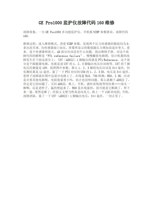
GE Pro1000监护仪故障代码160维修
GE Pro1000监护仪故障代码160维修
故障现象:一台GE Pro1000多功能监护仪,开机报NIBP参数错误,故障代码160。
维修过程:进入维修模式,查看NIBP参数,发现两个压力传感器的数值均为0。
拿出洗耳球,向传感器接口加压,屏幕所显示的数值随压力增加而逐步变大。
看来,连个传感器和放大、AD部分应该没有什么问题。
找出维修手册,对这个故障代码的解释是“PT1 reference failure”,慢慢翻看电路图,估计机器的故障发生在下面这部分上: U57(AD822)1脚输出的就是PT1 Reference。
这个部分是个跟随器电路,也就是说U57的1、2、3脚输出电压应该相等。
U57的7脚电压经测量是10V,按照图中参数,那么1、2、3脚的电压应该是344毫伏,但实测结果是11毫伏。
量了一下PT2对应的U58的1、2、3脚,电压是344毫伏。
看样子故障就在图中这部分电路上了。
在线量R18,750欧姆;R80,2.3K。
应该是并着其他电路呢,电阻值量着小吗,估计也没啥问题。
那么就剩下AD822了,肯定是它的问题了。
买回AD822,换上,开机,满怀喜悦地等待结果----迎头一棒啊,还是老样子。
猛的想起来了,R80是在线量的,很可能是它断路了。
焊下来一量,果然是断了,经验主义想当然真是坑死人。
换上一个21K的电阻,开机,故障消除,量了一下U57(AD822)1脚输出电压:344毫伏。
一切正常了。
GE PRO1000监护仪无显示故障一例

1 和 1 / 的 电 阻把 ③ ④ 脚 连接 在 ① 、②脚 2 k 14W k
之 间 ,使③④脚 的电压为 1 V左 右 ,由于该拆 机镇 流器 的尺寸较 大原来 的位 置不合适 安装 ,仔细观察 后 ,把镇 流器 固定 在 液 晶屏 和 主板 之 间 比较合 适 ,
Me i lE up n o .3, . d c q i me tV 1 2 No 2 a
GE PRo 1 0 监 护 仪 无 显 示 故 障 一 例 0 0
刘 新华 ,查宇 飞 ( 西双版 纳州人 民 医院 设 备科 ,云南 景洪 66 0 ) 6 10 故障现 象 :开机 液晶屏无光 栅 ,声 音和 面板 指 示灯正 常
②地 ,中间抽 头接③ ④脚来 调节灯 管的亮度 ,接通 外 接 电源调整 电位器 ,灯管亮 了,给监护仪通 电开
一
图 4 p w rcnrl 指示 灯 位 置 图 o e t 板 o o
测量一 下正 负高压 发生器 上 M A—L图 4中 3和 M A H图 4中 4问的采样 电阻 的阻值 ,这个 阻值应 该 为 25 . Q。机器 在使用 了一段 时 间后 这 个 阻值 就会
—
灯亮 时 ,如果问题 出在高 压发生 器部分 ,先要断 电
电路板 ,该 镇流器 可 以正 常使用 ,其上有 4 输入 根 连线 ( 电源 l V,②地 ,③ 开启 ,④亮度控 制 ) ① 2 , 2 灯 管插 座 ,就 用 该 镇 流 器 接 上 监 护 仪 背 光 灯 个
管 ,用 一个 1 k电位器 的两头分 别接① 电源 1 5 2V,
就 用加厚 的双 面胶把镇 流器粘 在液 晶面板后 面 ,上
GE Industrial Solutions 智能电机管理系统 EntelliPro 电机保护与电

GEIndustrial SolutionsGE imagination at workGE’s IntelligentMotor Management SystemEntelliPro Motor protection & Motor control2EntelliProMaintenance phaseB E N E F I T SFeatures and benefi tsEngineering phaseCommissioning phaseOperation phase3EntelliProES3ES5Protection• Overload (Class 5 to 40)• Earth fault (Residual current)) • Phase loss• Thermistor (PTC) • Start current • Blocked rotor • Under load• Maximum starts per time • Self monitoring• External device monitoring Options• 24 V DC or 110 – 240 V AC supplyDiagnostic• Time to overload trip, release • Number of operations • Number of motor starts • Motor ON-time, OFF-time • Number of overload trips • Number of thermistor trips • Maximum currents • Trip currentsMore• Local control and display devices • Profi bus DP and Modbus RTU • Profi bus DP certifi ed • Predefi ned control logic • Free programmable logic • SIL, ATEX certifi ed• I/O 7 digital inputs 3 digital outputs• I/O 16 digital inputs 8 digital outputs • 4–20 mA outputMotor Management System4EntelliProDemonstration kitMotor Management System• Motor protection • Motor control• Interface with process control and SCADA system • Status information from motors and switchgear • Maintenance information• Management of settings and confi gurationIN T EL L I G ENTCan be used for:• Personal training• Pre-testing the SCADA system• Pre-testing drive application settingsd for:EntelliPro5Integrated into MCC panels ...• SEN Plus • SEK/SEV 32EntelliPro6• Direct-on-line (DOL)• Reverse• Star delta• Star delta reverse• Softstarter• Softstarter reverse• Dahlander• Pole changing starter• Solenoid valve• ActuatorDrive typicals• The control logiccoordinatesthecommands from fourdifferent control unitsPredefi ned controllogic selectable1234Motor drive applicationTypical control logicEntelliPro7Motor Management SystemOrder information107166680839E/5390/E/EX 3.0 11/12© Copyright GE Industrial Solutions 2012GE imagination at workGEIndustrial SolutionsBelgiumGE Industrial Belgium Nieuwevaart 51B-9000 GentTel. +32 (0)9 265 21 11FinlandGE Industrial Solutions Kuortaneenkatu 2FI-00510 HelsinkiTel. +358 (0)10 394 3760FranceGE Industrial Solutions Paris Nord 213, rue de la PerdrixF-95958 Roissy CDG Cédex Tel. +33 (0)800 912 816GermanyGE Industrial Solutions Robert-Bosch Str. 2a D-50354 Hürth-Efferen Tel. +49 (0) 2233/ 9719-0HungaryGE Hungary Kft.Vaci ut 81-83.H-1139 Budapest Tel. +36 1 447 6050RussiaGE Industrial Solutions27/8, Electrozavodskaya street Moscow, 107023Tel. +7 495 937 11 11South AfricaGE Industrial Solutions Unit 4, 130 Gazelle Avenue Corporate Park Midrand 1685P.O. Box 76672 Wendywood 2144 Tel. +27 11 238 3000SpainGE Industrial Solutions P.I. Clot del Tufau, s/nE-08295 Sant Vicenç de Castellet Tel. +34 900 993 625United Arab Emirates GE Industrial Solutions Injaz Building, 3rd Floor Dubai Internet City PO Box 11549, Dubai Tel. +971 4 4546912United KingdomGE Industrial Solutions Houghton Centre Salthouse Road Blackmills Northampton NN4 7EXTel. +44 (0)800 587 1239ItalyGE Industrial SolutionsCentro Direzionale Colleoni Via Paracelso 16Palazzo Andromeda B1I-20864 Agrate Brianza (MB)Tel. +39 039 637 3701NetherlandsGE Industrial Solutions Parallelweg 10Nl-7482 CA Haaksbergen Tel. +31 (0)53 573 03 03PolandGE Power Controls Ul. Odrowaza 1503-310 WarszawaTel. +48 22 519 76 00Ul. Leszczyńska 643-300 Bielsko-Biała Tel. +48 33 828 62 33PortugalGE Industrial SolutionsRua Camilo Castelo Branco, 805Apartado 2770P-4401-601 Vila Nova de Gaia Tel. +351 22 374 60 00GE Industrial Solutions is a fi rst class global supplier of low and medium voltage products including wiring devices, residential and industrial electrical distribution components, automation products, enclosures and switchboards. Demand for the company’s products comes from wholesalers, installers, panelboard builders, contractors,OEMs and utilities /ex/industrialsolutions /uk/industrialsolutions。
Edge 1000讲解词-最终版
文档名称文档密级2023-7-23华为保密信息,未经授权禁止扩散 第1页, 共1页 Edge 1000讲解词大家好,接下来为您介绍华为Edge 1000一体化解决方案。
将会议管理平台、媒体处理平台、地址本、公私穿越服务器、GK/SIP 服务器融为一体,打造中小企业的全功能视频会议平台,轻量化部署,轻松实现总部与分支机构、企业内外部的灵活沟通。
All in one 设计:传统的视讯解决方案,此类传统解决方案往往是针对中大型企业设计,起步容量高、组件多且分散、安装交付也复杂,中小型企业常常只能望而却步,Edge 1000集成了SMC 、SC 和MCU 的功能,预装软件、极简配置,最快4小时即可上线。
支持25路并发,最大注册量1000,对于一些小型会议来说,只需要一台Edge 1000便可以轻松实现。
简洁会控:会议控制在后台操作,全新UI 界面,让会控更加简洁易用。
70余种会管会控功能,随需设定,还可以自定义常用模式,满足企业个性化需求。
原生远程协作能力:内置MCU 支持1080P 高清会议,原生的远程协作能力,使得会场两端在共享白板的同时实现双向协作,新一代数据高清编解码器,专注提升文字、渲染图、动画、图文混排场景压缩性能,可以实现4K 超清数据分享。
专业音视频能力:超强的网络自适应能力,最高支持30%视频丢包、80%音频丢包,保障会议的流畅体验。
专有的VME 技术,让画面更加细腻、自然且生动。
支持多种终端接入,不论是客户桌面、个人移动终端还是会议室大屏,都可以实现很好的融合。
便捷服务扩展:Edge 1000还支持服务的扩展。
可外扩MCU ,提升并发量至500路1080P 30fps ,搭配录播及智能会议服务器,还可以实现人脸签到、实时字幕和多模态会议记录等功能,为企业的视频会议提供更多的可选空间。
Intel千兆网卡PRO1000是什么意思
Intel千兆网卡PRO1000是什么意思经常有用户认为Intel PRO 1000是英特尔网卡的型号,实际上这个描述指的是Intel千兆速率的网卡,这一分类下包含很多型号,所以要如何选购一款合适千兆网卡首先要确认具体的型号。
Intel PRO 1000千兆网卡主要有5个系列:Intel PRO 1000 PT、Intel PRO 1000 MT、Intel PRO 1000PF、Intel PRO 1000 MF、Ibtel PRO1000GT用的较多的是Intel PRO1000 PT系列,尤其是IntelPRO/1000 PT Dual PortServer Adapter这款,这个描述对应的型号叫做EXPI9402PT,是英特尔一款千兆PCI-E双口网卡,对应接口类型为RJ-45,可用在PCI-E X4,X8,X16插槽上。
这款千兆双电口网卡的价格大约在八百左右是目前机器视觉和工控机行业首选的一个型号。
此外这个系列中还有一款四口千兆网卡,描述为Intel? PRO/1000 PTQuad Port Low Profile ServerAdapter,这个描述对应的型号叫做EXPI9404PTL,是Intel千兆网卡中比较早期的一款千兆四口网卡,对应接口类型同样为RJ-45,可用在PCI-E X4,X8,X16插槽上,价格大约在2千左右,在千兆PCI-E四口网卡的型号里是性价比较高的一款。
Intel PRO 1000 PF和Intel PRO 1000 MF这2个系列是千兆光纤网卡,由于成本相对较高,用的客户相对也较少,其中Intel PRO1000 PF千兆网卡是PCI-E接口的,Intel PRO 1000 MF是PCI接口的。
价格在一千五到两千五百元左右。
以上就是Intel PRO 1000千兆网卡的一些相关信,息更多技术参数和报价信息信息用户可咨询intel网卡分销中心华天易达科技有限公司,可提供更专业更合适的网卡选购方案。
GE彩超——精选推荐

GE彩超LOGIQ 500系列产品是GE 2001年推出的的B型彩⾊数字超声诊断仪,2007年后停⽌销售,由通⽤电⽓医疗系统(中国)有限公司⽣产,产地⽆锡;产品由(台车式)主机、超声探头和监视器等组成。
监视器为38cm彩⾊显⽰器、探头电缆⽀架、C358型(3.0MHz)凸阵探头等组成。
性能:显⽰⽅式:B、D、M、CFM、B/M等。
探头类型:凸阵、线阵、相控阵、弧阵、双翼、微凸阵等。
标配探头(C364)标称频率为3.5MHz,曲率半径为55mm,探测深度≧180mm,轴向分辨率≦1mm(深度≦80mm)产品适⽤于诊断头、颈、胸、腹、⾻盆、⽣殖器、四肢/⼿⾜、⼦宫、⼼脏等部位的软组织和⾎管疾病。
⼀、专业化PROfessionalismLOGIQ500PRO系列能够满⾜当今卫⽣医疗机构的最新要求,该系列具有双数字波束形成器、微⽶成像技术和最⼤⾎流分辨率的特点,能够在整个诊断过程提供稳定和⾼质量的图像,这是⼀个物美价廉的新系列。
你不需要增加成本就能够达到诊断⽬的。
使⽤数字化波束形成其能够同时进⾏近场和远场成像,不断调整由软件控制的信号时间差,并能够达到最佳的精确度。
使⽤数字化波束形成同时进⾏近长和远场成像,不断调整由软件控制的信号时间差,从⽽达到最佳的精确度。
⼆、⾼效率PROductivity尽量提⾼病⼈处理速度是LOGIQ500PRO系列许多优点之⼀,其中主要的理由是:以创新的能⼒使你所进⾏的检查合理化。
例如,⾃动组织优化只需按⼀个按钮就可以处理所有的图像资料,并调节到最佳检查状态,从⽽有效的节省时间。
右上图:没有使⽤⾃动组织优化技术。
右下图:使⽤⾃动组织优化技术。
三、更先进PROgressLOGIQ500PRO系列使你处于超声技术的前列,它具有许多先进能⼒,不仅包括有源⾯阵探头,三维显像,组织谐波成像和全新的脉动⾎流图(PFD)技术。
DICOM3.0⽹络结构的特点使它能够容易与GE超声波公司不断发展的新技术相结合。
- 1、下载文档前请自行甄别文档内容的完整性,平台不提供额外的编辑、内容补充、找答案等附加服务。
- 2、"仅部分预览"的文档,不可在线预览部分如存在完整性等问题,可反馈申请退款(可完整预览的文档不适用该条件!)。
- 3、如文档侵犯您的权益,请联系客服反馈,我们会尽快为您处理(人工客服工作时间:9:00-18:30)。
4 . 1 故障现象 :插上交流 电源线 ,面板交 流接入显示 灯不
亮 ,判 断 电 源 板 损 坏 。
4 . 2 分析与检修 :打开机盖 ,拔 下后备 电池 插头 ,拆 下电 源板 。经测 量发 现 保 险管 S I 1 、S I 2烧 毁 ,整 流桥 堆 烧毁 , 二极管 I M 、D 7被击穿 。更换 D 4 、D 7及 保险管后 ,测量初 级无短路现象存在后 , 加电测量输 出 电压 2 4 V正 常 ,将 电 源板装上机器开机一小时未发现其他异 常 ,故 障排 除。
一
检查排 除故 障 ;若 没有 测量值 ,则可 能是血 氧探头 连线 线
损坏或探头 损坏 。把血 氧探 头万用 表连 接 ,通过扭 折插 头 根部 和探头 根部 ,观察 万用 表 的显 示变 化 ,判断 哪一源部 分 损 坏 严 重无 法 维 修 ,可 用
5 总 结
个光敏二级管 对应 的插头 针脚进 行测 量 ,两个 红外 发光
管通常 为 1 . 5 V 1 . 0 V,光敏 二极管 通常 为 0 。 7 V。若数值 正
确 ,则 血 氧 探 头 良好 ,可 能 是 插 头 与 主 机 连 接 处 出 现 问题 ,
除上述外 ,对该 机器 出现故 障 的处理 ,我 们也 得 出 了
( 1 ) :7 4—7 5 .
子 引脚是否 有污垢 ,若 有则 清除 。然 后重新 测量 数值 ,若 符合测量值 ,重 新焊接 后可 正常 卫作 ;若不 符合则 管子 损
收 稿 日期 :2 0 1 5—0 4— 0 2
[ 2 ]孟庆 . P h i l i p s M P 5 0监 护 仪 维修 案 例 [ J ] .中 国 医学 装 备 ,
2 4 v直流 电源替 代 ,代替 后机 器 运行 状态 良好 ,且 经 过长 期测试使用至今依 然正 常工作 ;一些 常用 的配件 要准 备齐 全 ,如血压连接管 内 的胶 圈 、电 阻 、电容 、整 流桥 、三极
部 出现故 障 ,进行检修 。若通 过扭 折 ,探头 不亮 ,没找 到
原 因 ,可从 探 头 根 部 切 开 连 线 ,对 连 线 和 探 头 分 别 测 量 。
G E Pr o l O O O型 多 参 数 监 护 仪 维 修 四例
徐 伟 然
( 天 津 市第 四 医院,天 津 3 0 0 2 2 2 )
【 中图分类号]T H 7 7 2 . 2 【 文献标识码]c 【 文章编号] 1 0 0 2 — 2 3 7 6( 2 0 1 5 )0 7 — 0 1 3 5— 0 1
[ 摘
要 ] 随着科 学技术 的飞速发展 ,监护仪 作为一 种常 用设 备 ,在各 级 医院 中得 到广泛应 用。监护仪
能够对患者的心 电、血压、血氧等参数进行 实时 ,准确 ,长期 的监 测。 当前 已经被 广 泛应 用于危重 患者监护 、 麻 醉、急救 等 医疗环节 中,给 治疗、临床诊 断、危重患者的抢救提供 了可靠的数据信息 支持 ,具有十分重要 的 作用。本文就结合案例 ,对 G E P r o l 0 0 0型多参数 监护仪 维修进 行分析研 究。
过 因没拔先吃插 头而将 主板烧 坏 的先例 。对 主板 右上 角有
一
组 白色排线进 行重 新插 拔 ,开机后 正 常 ,再 以热 熔胶 加
固 ,故障排除 。相反 ,若开 机故 障依 旧 ,则需 要将 主板 上 的各个插头拔 下 ,小心 拆下 主板 ,主板 右上 角排 线的 另一 端与前面板相 连 ,重新 插拔 ,开机后 正常 ,再 以热 熔胶 加 固,故障排除 。
乎 为零 ,且该 电池为 3 . 7 V充电电池 。由于此 电池为非 标准 件且价格 昂贵 ,不易更 换 ,用手 机充 电 电池 替代 。原 电池
两端引 导线 两条 ,将新 电池 固定 在侧板 上 ,开机更 改 为 中 文界 面,将 时间调准 ,此后运行正常 ,故障消除 。
故 障 四 2 故 障 二 :血 氧 故 障
以上 。 由此 判 断 该 机 器 存 储 配 置 的 电池 电量 不 足 。
3 . 1 故障现象 :开机有声音 ,显示器花屏 3 . 2 分析 与检 修 :打 开 机 盖后 ,大家 一 定要 注 意 这个 问 题 ,拔掉电池插 头再进 行维 修。这一 步非 常重 要 ,曾经 有
1 . 2 分析及处理 :打开机盖找 到电池 ,测 电池两 端 电压 几
管等 。当我们碰 到各 种维修 故障 时 ,只要 细心 观察 、仔 细
研究 ,总会找到解决方案 ,更好 的为一线服务 。
如果检测到 连线断 裂 ,进行 焊接或 剪短 或换线 处理 。若 探 头 内两 红外 发光管 、光 敏二 极管测 量值 不符合 ,先 观察 管
[ 参考文献】
[ 1 ] 陈建 勤 . P M 9 0 0 0监 护 仪 维 修 实 例 [ J ] .医疗 装 备 ,2 0 1 4
4 无 法 开 机
2 . 1 故 障现象 :显示器不显示血氧饱和度波形和脉搏 。 2 . 2 分析 与检修 :先更 换 同类 型且 使用 良好 的血 氧探 头 , 连接此监护 仪 ,如 出现 血氧 波形 与脉搏 正常 ,则说 明 血氧 模板 良好 ,是 血氧探 头 损坏 ;若 没 出现血 氧 波形 和 脉搏 , 则是机 内血 氧模块损坏 ,需维修或更换 。 对血氧探 头检 修 。拆 开 血 氧探 头 与主 机 连接 的插 头 , 用万用表二 极 管档 对探 头组 成元 件 两个 红 色发 光二 极 管 ,
[ 关键词 ]G E p r o l 0 0 0监 护仪 ;多参数 ;维修
1 故 障 一 :系 统 时 间 不 准
坏 ,更换后可正常工作 。
3 故 障三 :开 机 花 屏
1 . 1 故 障现象 :系统 时间不准 ,且 变成英文 界面 ,更 改成
中文界面使 用一个 月后又 变成英文 ,且 该机器 已使用 5年
