PLL350-2140中文资料
FPGA可编程逻辑器件芯片EP3C40F324I7N中文规格书
Configuration & Testing 1An encryption configuration file is the same size as a non-encryption configuration file. When using a serial configurationscheme such as passive serial (PS) or active serial (AS),configuration time is the same whether or not the designsecurity feature is enabled. If the fast passive parallel (FPP)scheme us used with the design security or decompressionfeature, a 4× DCLK is required. This results in a slowerconfiguration time when compared to the configuration time ofan FPGA that has neither the design security, nordecompression feature enabled. For more information aboutthis feature, refer to AN 341: Using the Design Security Feature inStratix II Devices. Contact your local Altera sales representativeto request this document.Device Configuration Data DecompressionStratix II FPGAs support decompression of configuration data, which saves configuration memory space and time. This feature allows you to store compressed configuration data in configuration devices or other memory, and transmit this compressed bit stream to Stratix II FPGAs. During configuration, the Stratix II FPGA decompresses the bit stream in real time and programs its SRAM cells.Stratix II FPGAs support decompression in the FPP (when using a MAX II device/microprocessor and flash memory), AS and PS configuration schemes. Decompression is not supported in the PPA configuration scheme nor in JTAG-based configuration.Remote System UpgradesShortened design cycles, evolving standards, and system deployments in remote locations are difficult challenges faced by modern system designers. Stratix II devices can help effectively deal with these challenges with their inherent re-programmability and dedicated circuitry to perform remote system updates. Remote system updates help deliver feature enhancements and bug fixes without costly recalls, reduce time to market, and extend product life.Stratix II FPGAs feature dedicated remote system upgrade circuitry to facilitate remote system updates. Soft logic (Nios® processor or user logic) implemented in the Stratix II device can download a new configuration image from a remote location, store it in configuration memory, and direct the dedicated remote system upgrade circuitry to initiate a reconfiguration cycle. The dedicated circuitry performs error detection during and after the configuration process, recovers from any error condition by reverting back to a safe configuration image, and providesStratix II Device Handbook, Volume 15.DC & SwitchingCharacteristicsOperating Conditions Stratix®II devices are offered in both commercial and industrial grades. Industrial devices are offered in -4 speed grades and commercial devices are offered in -3 (fastest), -4, -5 speed grades.Tables5–1 through 5–32 provide information about absolute maximum ratings, recommended operating conditions, DC electrical characteristics, and other specifications for Stratix II devices.Absolute Maximum RatingsTable5–1 contains the absolute maximum ratings for the Stratix II device family.Table5–1.Stratix II Device Absolute Maximum Ratings Notes(1), (2),(3)Symbol Parameter Conditions Minimum Maximum Unit V CCINT Supply voltage With respect to ground–0.5 1.8VV CCIO Supply voltage With respect to ground–0.5 4.6VV CCPD Supply voltage With respect to ground–0.5 4.6VV CCA Analog power supply forPLLsWith respect to ground–0.5 1.8VV CCD Digital power supply for PLLs With respect to ground–0.5 1.8VV I DC input voltage (4)–0.5 4.6VI OUT DC output current, per pin–2540mAT STG Storage temperature No bias–65150°CT J Junction temperature BGA packages under bias–55125°C Notes to Tables5–1(1)See the Operating Requirements for Altera Devices Data Sheet.(2)Conditions beyond those listed in Table5–1 may cause permanent damage to a device. Additionally, deviceoperation at the absolute maximum ratings for extended periods of time may have adverse affects on the device.(3)Supply voltage specifications apply to voltage readings taken at the device pins, not at the power supply.(4)During transitions, the inputs may overshoot to the voltage shown in Table5–2 based upon the input duty cycle.The DC case is equivalent to 100% duty cycle. During transitions, the inputs may undershoot to –2.0 V for input currents less than 100mA and periods shorter than 20ns.Timing ModelTable5–42.M-RAM Block Internal Timing Microparameters(Part 1 of2)Note(1)Symbol Parameter-3 SpeedGrade (2)-3 SpeedGrade (3)-4 SpeedGrade-5 SpeedGradeUnit Min(4)MaxMin(4)MaxMin(5)MaxMin(4)Maxt M E G A R C Synchronous read cycletime 1,8662,774 1,8662,9111,7771,8663,189 1,7771,8663,716 pst M E G AW E R E S U Write or read enablesetup time before clock 144 151 165165192pst M E G AW E R E H Write or read enablehold time after clock 39 40 444452pst M E G A B E S U Byte enable setup timebefore clock 50 52 575767pst M E G A B E H Byte enable hold timeafter clock 39 40 444452pst M E G A DATA A S U A port data setup timebefore clock 50 52 575767pst M E G A DATA A H A port data hold timeafter clock 243 255 279279325pst M E G A A D D R A S U A port address setuptime before clock 589 618 677677789pst M E G A A D D R A H A port address hold timeafter clock 241 253 277277322pst M E G A DATA B S U B port setup time beforeclock 50 52 575767pst M E G A DATA B H B port hold time afterclock 243 255 279279325pst M E G A A D D R B S U B port address setuptime before clock 589 618 677677789pst M E G A A D D R B H B port address hold timeafter clock 241 253 277277322pst M E G A DATAC O1Clock-to-output delaywhen using outputregisters 480715 480749457480821 480957pst M E G A DATAC O2Clock-to-output delaywithout output registers 1,9502,899 1,9503,0421,8571,9503,332 1,9503,884 pst M E G AC L K L Minimum clock low time1,2501,3121,4371,4371,675psStratix II Device Handbook, Volume 1Document Revision HistoryAltera Corporation Stratix II Device Handbook, Volume 1July 2009Clock ManagementStratix II Device Handbook, Volume 2Section I–2。
PT4302中文规格书

V1.1C
4
February 2010
For NaterTech
PT4302
由于 PT4302 无镜频讯号消除的功能,所以本振频率可以比发射频率高或低。但因频率低耗电少一些,所以如无其它原 因,建议使用较低的频率。下表列出几个对应发射频率使用的晶振。 发射器频率 fTX 315 MHz 340 MHz 390 MHz 433.92 MHz PT4302 晶振频率 fREFOSC 9.509 MHz 10.29 MHz 11.853 MHz 13.226 MHz
注: 1. L1 和 C1 为输入匹配使用,需依不同的电路板或天线作微调。 2. C5 需依据不同的传输速率或编码型式作调整。 3. F1 是 10.7 MHz 的陶磁滤波器,建议使用型号是 Murata SFELA10M7HA00-B0。 4. Option 部份的零件可视需要使用。
V1.1C
2
February 2010
数据滤波器
数据滤波器主要功用是消除 OOK/ASK 解调后的噪声,解调器频宽可以依据不同应用来作选择,原则上可参考下面的关 系式: BWDF = 0.65 / 最短的数据宽度 (BWDF:数据滤波器频宽) PT4302 数据滤波器频宽可经由输入脚 SELA 和 SELB 作调整,因为参考频率来自晶振,所以频宽会和操作频率有关。下 面列出两个常用频段其数据滤波器频宽的设定值。 SELA 1 1 0 0 SELB 1 0 1 0 数据滤波器频宽 BWDF fRF = 315 MHz fRF = 433.92 MHz 900 Hz 1250 Hz 1800 Hz 2500 Hz 3600 Hz 5000 Hz 7200 Hz 10000 Hz
ASK 解调器
OOK/ASK 讯号经由降频到 10.7 MHz,由外部阻抗为 330 奥姆的陶瓷滤波器过滤噪声。此 10.7 MHz 的中频讯号经对数 放大器放大后形成 RSSI 讯号,后续的解调工作则是经由比较 RSSI 的讯号所达成。RSSI 讯号经过数据滤波器消除高频 讯号,再由数据产生器比较出所需的解调数据。
锁相环电路概述
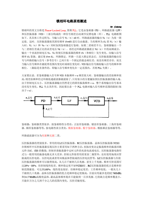
锁相环电路原理概述By jluhong 锁相环的英文全称是Phase-Locked Loop,简称PLL。
它是由鉴相器(PD)、环路滤波器(LPF)和压控振荡器(VCO)三部分构成的一种信号相差自动调节反馈电路(环)。
PLL电路框图如下,其具体工作过程为,当输入信号Vi(t)=0时,环路滤波器的输出Vc(t)为某一固定值。
这时,压控振荡器按其固有频率fv=f0进行自由振荡。
当有频率为fi的Vi(t)输入时,Vi(t)和Vo(t)同时加到鉴相器进行鉴相。
如果二者相差不大,鉴相器输出一个与二者相位差成正比的误差电压Vd(t),再经过环路滤波器滤去Vd(t)中的高频成分,输出一个直流控制电压Vc,Vc将使压控振荡器的频率fv(和相位)发生变化,向输入信号频率fi靠拢,最后使fv= fi,环路锁定。
环路一旦进入锁定状态后,压控振荡器的输出信号与环路的输入信号(参考信号)之间只有一个固定的稳态相位差,而没有频差存在,而且当输入信号频率在捕捉带范围内变化时或相位变化时,VCO输出信号跟踪输入信号的频率和相位。
(跟踪是有条件的,即输入信号频率变化在一定范围内,否则PLL失锁)。
大家要注意,若鉴相器输入信号和VCO本振频率ωo频差很大时,鉴相器输出的差拍频率很高,则差拍频率经过环路低通滤波器被滤除了。
只有很小的分量漏加到压控振荡器的输入端。
由于控制电压太小,压控振荡器输出仍然是它的固有振荡频率ωo,整个系统输出信号基本没有发生变化,PLL失去其作用,因此要注意一个PLL电路对输入信号频率范围的限制(取决于ωo)。
鉴相器:鉴相器类型很多。
按鉴相特性分类有:正弦形鉴相器、锯齿形鉴相器、三角形鉴相器、梯形鉴相器等等;按电路性质分类有:模拟鉴相器、数字鉴相器、模拟乘法鉴相器等等。
环路滤波器可分为有源和无源二类。
压控振荡器的类别很多,常用的有LC压控振荡器,RC压控振荡器,晶体压控振荡器(VCXO)在锁相环中压控振荡器实现压控主要采用如下两种方法:直接改变决定振荡频率的振荡回路元件(如C、或R)的数值;控制多谐振荡器中定时元件的充放电流或电压。
PLL350-265资料

VCO PLL IC Supply Current:
VCO PLL IC Spurious Product - 200 kHz Harmonic Suppression: 2nd Harmonic 3rd Harmonic Ref Osc Signal: Frequency Amplitude Phase Noise - 1 kHz Input Impedance
元器件交易网
PLL Product Specification
Model:
PLL350-265(Y)
Customer:
SIRENZA MICRODEVICES, INC.
Rev: P3 Date: 9/1/2006 AppNote: 113, Opt. 207000
Operating Temperature Range: ( -35 ° to 85 ° C)
Page 1 of 1
Sirenza Microdevices, Inc.
303 S. Ct.
Broomfield, CO 80021
tel 303.327.3030 fax 303.410.7988
RoHS Compliant
To order models as RoHS Compliant add "Y" suffix to base model number.
Parameter Frequency Range Step Size Settling Time - to within 1.0 kHz Output Power Output Phase Noise:
Output Impedance -
LM350BT#中文资料

ELECTRICAL CHARACTERISTICS (VI–VO = 5.0 V; IL = 1.5 A; TJ = Tlow to Thigh; Pmax [Note 1], unless otherwise noted.)
Characteristics Line Regulation (Note 2) TA = 25°C, 3.0 V ≤ VI–VO ≤ 35 V Load Regulation (Note 2) TA = 25°C, 10 mA ≤ Il ≤ 3.0 A VO ≤ 5.0 V VO ≥ 5.0 V Thermal Regulation, Pulse = 20 ms, (TA = +25°C) Adjustment Pin Current Adjustment Pin Current Change 3.0 V ≤ VI–VO ≤ 35 V 10 mA ≤ IL ≤ 3.0 A, PD ≤ Pmax Reference Voltage 3.0 V ≤ VI–VO ≤ 35 V 10 mA ≤ IO ≤ 3.0 A, PD ≤ Pmax Line Regulation (Note 2) 3.0 V ≤ VI–VO ≤ 35 V Load Regulation (Note 2) 10 mA ≤ IL ≤ 3.0 A VO ≤ 5.0 V VO ≥ 5.0 V Temperature Stability (Tlow ≤ TJ ≤ Thigh) Minimum Load Current to Maintain Regulation (VI–VO = 35 V) Maximum Output Current VI–VO ≤ 10 V, PD ≤ Pmax VI–VO = 30 V, PD ≤ Pmax, TA = 25°C RMS Noise, % of VO TA= 25°C, 10 Hz ≤ f ≤ 10 kHz Ripple Rejection, VO = 10 V, f = 120 Hz (Note 3) Without CAdj CAdj = 10 µF Long Term Stability, TJ = Thigh (Note 4) TA= 25°C for Endpoint Measurements Thermal Resistance, Junction–to–Case Peak (Note 5) Average (Note 6) 4 3 1,2 Figure 1 2 Symbol Regline Regload – – Regtherm IAdj ∆IAdj – – – 5.0 0.1 0.002 50 0.2 25 0.5 – 100 5.0 mV % VO % VO/W µA µA Min – Typ 0.0005 Max 0.03 Unit %/V
PLL502-24中文资料
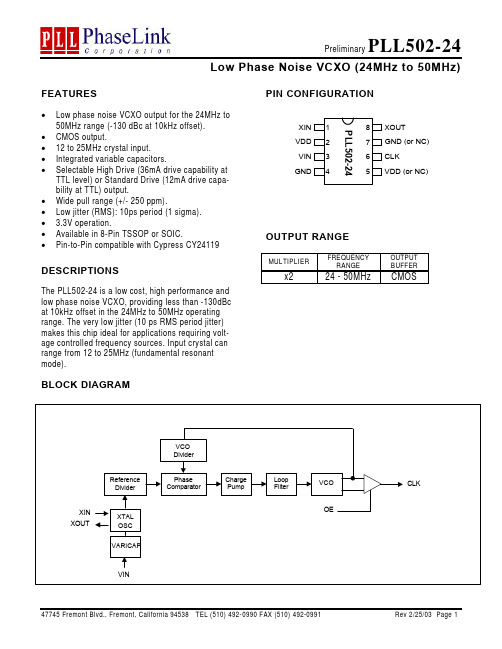
FEATURES• Low phase noise VCXO output for the 24MHz to50MHz range (-130 dBc at 10kHz offset). • CMOS output.• 12 to 25MHz crystal input. • Integrated variable capacitors.• Selectable High Drive (36mA drive capability atTTL level) or Standard Drive (12mA drive capa-bility at TTL) output.• Wide pull range (+/- 250 ppm).• Low jitter (RMS): 10ps period (1 sigma). • 3.3V operation.• Available in 8-Pin TSSOP or SOIC.• Pin-to-Pin compatible with Cypress CY24119DESCRIPTIONSThe PLL502-24 is a low cost, high performance and low phase noise VCXO, providing less than -130dBc at 10kHz offset in the 24MHz to 50MHz operating range. The very low jitter (10 ps RMS period jitter) makes this chip ideal for applications requiring volt-age controlled frequency sources. Input crystal can range from 12 to 25MHz (fundamental resonant mode).PIN CONFIGURATIONOUTPUT RANGEMULTIPLIERFREQUENCY RANGEOUTPUT BUFFERx2 24 - 50MHz CMOSBLOCK DIAGRAMPLL502-2412345678XIN VDD VIN GNDXOUT CLK VDD (or NC)GND (or NC)PIN DESCRIPTIONSName Number Type DescriptionXIN 1 I Crystal input pin.VDD 2, 5 P +3.3V VDD power supply pin (pin 5 is optional).VIN 3 I Frequency control voltage input pin.GND 4, 7 P Ground pin (pin 7 is optional).CLK 6 O Output clock pin.XOUT 8 I Crystal output pin.ELECTRICAL SPECIFICATIONS1. Absolute Maximum RatingsPARAMETERS SYMBOL MIN. MAX. UNITS Supply Voltage Range V CC-0.5 7 V Input Voltage Range V I-0.5 V CC+0.5 V Output Voltage Range V O-0.5 V CC+0.5 V Soldering Temperature 260 °C Storage Temperature T S-65 150 °C Ambient Operating Temperature* -40 85 °C Exposure of the device under conditions beyond the limits specified by Maximum Ratings for extended periods may cause permanent damage to the device and affect product reliability. These conditions represent a stress rating only, and functional operations of the device at these or any other conditions above the operational limits noted in this specification is not implied.* Note: Operating Temperature is guaranteed by design for all parts (COMMERCIAL and INDUSTRIAL), but tested for INDUSTRIAL grade only.2. AC Electrical SpecificationsPARAMETERS SYMBOL CONDITIONS MIN. TYP. MAX. UNITS Input Crystal Frequency 12 25 MHz0.8V ~ 2.0V with 10 pF load 1.15Output Clock Rise/Fall Time(Low Drive) 0.3V ~ 3.0V with 15 pF load 3.70.8V ~ 2.0V with 10 pF load 0.5Output Clock Rise/Fall Time(High Drive) 0.3V ~ 3.0V with 15 pF load 1.5nsOutput Clock Duty Cycle Measured @ 1.4V 45 50 55 % Short Circuit Current ±50 mA 3. Voltage Control Crystal OscillatorPARAMETERS SYMBOL CONDITIONS MIN. TYP. MAX. UNITS VCXO Stabilization Time * T VCXOSTB From power valid 10 msVCXO Tuning Range F XIN = 12 – 25MHz;XTAL C0/C1 < 250500 ppmCLK output pullability 0V ≤ VIN ≤ 3.3V ±250 ppm VCXO Tuning Characteristic 165 ppm/V Pull range linearity 10 % VCON pin input impedance 2000 kΩVCON modulation BW 0V ≤ VIN ≤ 3.3V, -3dB 25 kHz Note: Parameters denoted with an asterisk (*) represent nominal characterization data and are not production tested to any specific limits.4. Jitter and Phase Noise specificationPARAMETERS CONDITIONS MIN. TYP. MAX. UNITSRMS Period Jitter(1 sigma – 1000 samples) at 44MHz, with capacitivedecoupling between VDDand GND.10 psPhase Noise relative to carrier 44MHz @100Hz offset -80 dBc/Hz Phase Noise relative to carrier 44MHz @1kHz offset -110 dBc/Hz Phase Noise relative to carrier 44MHz @10kHz offset -130 dBc/Hz Phase Noise relative to carrier 44MHz @100kHz offset -123 dBc/Hz Phase Noise relative to carrier 44MHz @1MHz offset -124 dBc/Hz5. DC SpecificationPARAMETERS SYMBOL CONDITIONS MIN. TYP. MAX. UNITSSupply Current, Dynamic, with Loaded Outputs I DDF XIN = 12 - 25MHzOuput load of 10pF16 20 mAOperating Voltage V DD 3.13 3.47 V Output High Voltage V OH I OH = -12mA (low drive) 2.4 V Output Low Voltage V OL I LO = 12mA (low drive) 0.4 V Output High Voltage atCMOS levelV OHC I OH = -4mA (low drive) V DD – 0.4 V Output drive current At TTL level (High drive) 36 51 mAAt TTL level (Low drive) 12 17 mA Short Circuit Current ±50 mA VCXO Control Voltage VCON 0 3.3 V ESD Protection Human Body Model 30006. Crystal SpecificationsPARAMETERS SYMBOL MIN. TYP. MAX. UNITSCrystal Resonator Frequency F XIN12 25 MHzCrystal Loading Capacitance Rating C L (xtal)9.5 pFC0/C1 250 -ESR R S30 ΩNote: Crystal Loading rating: 9.5pF is the loading the crystal sees from the VCXO chip at VCON = 1.65V. It is assumed that the crystal will be at nominal frequency at this load. If the crystal requires more load to be at nominal frequency, the additional load must be added externally.This however may reduce the pull range.PACKAGE INFORMATIONEORDERING INFORMATIONFor part ordering, please contact our Sales Department:47745 Fremont Blvd., Fremont, CA 94538, USATel: (510) 492-0990 Fax: (510) 492-0991PART NUMBERThe order number for this device is a combination of the following:Device number, Package type and Operating temperature rangePLL502-24 X CPART NUMBERTEMPERATURATUREC=COMMERCIALM=MILITARYI=INDUSTRALPACKAGE TYPES=SOIC, O=TSSOPPhaseLink Corporation, reserves the right to make changes in its products or specifications, or both at any time without notice. The information fur-nished by Phaselink is believed to be accurate and reliable. However, PhaseLink makes no guarantee or warranty concerning the accuracy of said information and shall not be responsible for any loss or damage of whatever nature resulting from the use of, or reliance upon this product.LIFE SUPPORT POLICY: PhaseLink’s products are not authorized for use as critical components in life support devices or systems without the ex-press written approval of the President of PhaseLink Corporation.。
铁羧葡胺磁化标记大鼠骨髓间充质干细胞的有效性及安全性研究

铁羧葡胺磁化标记大鼠骨髓间充质干细胞的有效性及安全性研究李冰玉;沈运丽;黄浙勇;孙爱军;钱菊英;邹云增;葛均波【摘要】目的:探讨超顺磁性氧化铁纳米颗粒(superparamagnetic iron oxide nanoparticles,SPIONs)铁羧葡胺(SHU 555A,商品名为Resovist)标记大鼠骨髓间充质干细胞(mesenchymal stem cells,MSCs)的有效性及安全性.方法:分离培养大鼠骨髓MSCs,将其与50 μg/mL Resovist共孵育24 h,并暴露于中心表面磁感应强度0.6 T磁场,采用普鲁士蓝染色、细胞透射电镜、原子吸收分光光度法检测细胞标记效率,采用细胞增殖试验及细胞活力检查观察细胞的标记毒性.结果:大鼠MSCs经Resovist标记后,普鲁士蓝染色显示,细胞内均可见大量着色颗粒,标记率接近100%;电镜检查显示,胞质内有含铁致密颗粒囊泡,未见氧化铁对细胞微细结构的破坏和毒性作用;原子吸收分光光度法测定结果显示,细胞平均铁含量(21.77±3.62)pg.Resovist标记和外加磁场对细胞增殖能力、细胞活力均无明显影响.结论:Resovist标记大鼠骨髓MSCs高效、安全,在细胞磁靶向方面具有临床应用潜力.【期刊名称】《中国临床医学》【年(卷),期】2014(021)002【总页数】4页(P111-114)【关键词】超顺磁性氧化铁纳米颗粒;间充质干细胞;磁化标记【作者】李冰玉;沈运丽;黄浙勇;孙爱军;钱菊英;邹云增;葛均波【作者单位】复旦大学附属中山医院实验室,上海200032;同济大学附属东方医院心内科,上海 200120;复旦大学附属中山医院心内科,上海200032;复旦大学附属中山医院实验室,上海200032;复旦大学附属中山医院心内科,上海200032;复旦大学附属中山医院心内科,上海200032;复旦大学附属中山医院心内科,上海200032【正文语种】中文【中图分类】R329干细胞移植是治疗全身退行性疾病、细胞坏死性疾病的新兴方法。
pll锁相环基本参数
pll锁相环基本参数PLL锁相环(Phase-Locked Loop)是一种常见的电子电路,用于将输入信号的相位和频率与参考信号保持一致。
它由相位比较器、环形滤波器、振荡器和分频器组成,通过不断调节VCO(Voltage Controlled Oscillator)的控制电压,使输出信号与参考信号同步。
PLL锁相环的基本参数有以下几个:1. 相位比较器的灵敏度:相位比较器用于比较输入信号和参考信号的相位差,并产生一个误差信号。
相位比较器的灵敏度决定了它对相位差的敏感程度。
灵敏度越高,PLL对相位差的纠正能力越强。
2. 环形滤波器的带宽:环形滤波器用于滤除相位比较器输出的误差信号中的高频噪声,使VCO的控制电压平稳变化。
环形滤波器的带宽决定了PLL的跟踪能力和抑制高频噪声的能力。
带宽越宽,PLL 的跟踪速度越快,但容易受到高频干扰;带宽越窄,抑制高频噪声的能力越强,但跟踪速度较慢。
3. 振荡器的频率稳定性:振荡器作为PLL的输出信号源,其频率稳定性对整个PLL性能的影响很大。
频率稳定性是指振荡器输出频率的变化范围,一般用频率漂移来表示。
频率漂移越小,PLL的稳定性越好。
4. 分频器的分频比:分频器将振荡器的输出信号进行分频,以便与参考信号相比较。
分频比的选择与输入信号和参考信号的频率关系密切,合适的分频比可以使PLL的锁定范围更广。
PLL锁相环在许多领域都有广泛的应用,例如通信系统、数据存储、音视频处理等。
以通信系统为例,PLL锁相环可以用于时钟恢复、频率合成和时钟同步等功能。
在时钟恢复中,输入信号经过相位比较器和环形滤波器处理后,控制VCO的输出,使其频率和相位与输入信号保持一致;在频率合成中,输入信号经过分频器和相位比较器处理后,控制VCO的输出,使其频率为输入信号的整数倍;在时钟同步中,参考信号和本地时钟通过相位比较器进行比较,通过调节VCO的控制电压,使本地时钟与参考信号同步。
除了以上基本参数外,PLL锁相环还有一些扩展参数,例如锁定时间和失锁检测等。
MCK12140D中文资料

PIN CONNECTIONS
VCC 8 R 7 V 6 VEE 5
LOGIC DIAGRAM
1 U (fR > fV) R R S S R V D (fV > fR) Device MCH1214OD MCK12140D Q D (fV > fR) Q U (fR > fV) U
2 U
3 D
4 D
元器件交易网
Order this document By MCH12140/D
Phase Frequency Detector
The MCH/K12140 is a phase frequency-detector intended for phase-locked loop applications which require a minimum amount of phase and frequency difference at lock. When used in conjunction with the MC12147, MC12148 or MC12149 VCO, a high bandwidth PLL can be realized. The device is functionally compatible with the MC12040 phase-frequency detector, however the MOSAIC™ III process is used to push the maximum frequency to 800 MHz and significantly reduce the dead zone of the detector. When the Reference (R) and VCO (V) inputs are unequal in frequency and/or phase, the differential UP (U) and DOWN (D) outputs will provide pulse streams which when subtracted and integrated provide an error voltage for control of a VCO. The device is packaged in a small outline, surface mount 8-lead SOIC package. There are two versions of the device to provide I/O compatibility to the two existing ECL standards. The MCH12140 is compatible with MECL10H™ logic levels while the MCK12140 is compatible to 100K ECL logic levels. This device can also be used in +5.0 V systems. Please refer to Motorola Application Note AN1406/D, “Designing with PECL (ECL at +5.0 V)” for more information.
adi锁相环配置参数

adi锁相环配置参数
ADI锁相环(PLL)是一种控制系统,用于将输入信号的相位和
频率与参考信号同步。
ADI公司提供了多种不同型号的锁相环芯片,每个型号都有不同的配置参数。
一般来说,ADI锁相环的配置参数
包括但不限于以下几个方面:
1. 输入信号频率和幅度,这些参数确定了锁相环需要跟踪的输
入信号的频率范围和幅度范围。
对于ADI锁相环芯片,通常会有特
定的输入频率范围和输入幅度范围的要求。
2. 参考信号频率和幅度,参考信号是锁相环的参考基准,其频
率和幅度对锁相环的性能和稳定性有重要影响。
配置参数中需要指
定参考信号的频率范围和幅度范围。
3. 锁相环环路滤波器参数,环路滤波器是锁相环中的重要组成
部分,其参数包括带宽、阶数、衰减等,这些参数会影响锁相环的
响应速度、抑制噪声等性能。
4. 输出参数,ADI锁相环芯片通常会有多种输出模式和输出接
口可选,配置参数需要包括输出信号的频率范围、幅度范围、输出
电平等。
5. 控制参数,锁相环的控制参数包括锁定时间、抖动性能、温度稳定性等,这些参数会影响锁相环的性能指标和稳定性。
在实际应用中,根据具体的系统需求和性能指标,需要根据数据手册和应用指南来配置ADI锁相环芯片的参数,以实现最佳的性能和稳定性。
同时,还需要考虑到电路设计、布局和调试等方面的因素,以确保锁相环能够正常工作并满足系统要求。
普瑞蓝功率芯片自制中文规格书
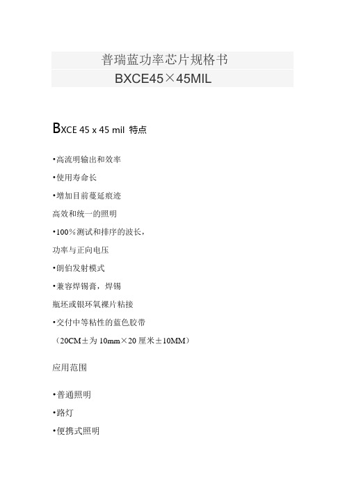
普瑞蓝功率芯片规格书BXCE45×45MILB XCE 45 x 45 mil 特点•高流明输出和效率•使用寿命长•增加目前蔓延痕迹高效和统一的照明•100%测试和排序的波长,功率与正向电压•朗伯发射模式•兼容焊锡膏,焊锡瓶坯或银环氧裸片粘接•交付中等粘性的蓝色胶带(20CM±为10mm×20厘米±10MM)应用范围•普通照明•路灯•便携式照明•建筑照明•定向照明•广域照明•显示背光•数码相机闪光灯•汽车照明•白光LEDLED芯片结构图产品命名方式:B XC E 4 5 4 5 X X X – Y Y – ZBXCE:指定产品系列4545:指定芯片尺寸(45 MIL×45 MIL)XXX:指定主导波长YY:指定辐射功率Z:指定正向电压机械尺寸6。
磁带应存放在垂直方向,而不是水平堆放。
磁带堆叠可以放置过大的压力,对LED的焊盘,导致焊线实力降低。
环保法规:普瑞致力于固态照明市场提供环保产品。
普瑞BXCE4545蓝色功率芯片是符合欧盟对电子设备的指令,即RoHS指令对有害物质的限制。
普瑞不会故意对BXCE4545模具产品添加以下限制材料:铅,汞,镉,六价铬,多溴联苯(PBB)或多溴二苯醚(PBDE)关于普瑞:普瑞是由40亿美金升值到100亿美金的全球照明行业的技术和解决方案的领先开发商和制造商。
总部设在加利福尼亚州利弗莫尔,普瑞是固态照明(SSL)的先驱,发光二极管(LED)技术,扩大市场,拉低了LED照明系统的成本。
普瑞的专利灯源技术取代与整合,固态照明解决方案,使灯具和照明设备制造商,以高的性能和迅速增长的能源效率的白色光(如白炽灯,卤素灯,荧光灯和高强度放电照明)传统技术内部和外部照明市场,包括路灯,商业照明和消费电子应用。
普瑞是与500多个专利申请或授予全球唯一垂直整合的LED制造商和专门开发固态光源照明行业设计的解决方案。
FPGA可编程逻辑器件芯片EP4SGX230FF35I3N中文规格书
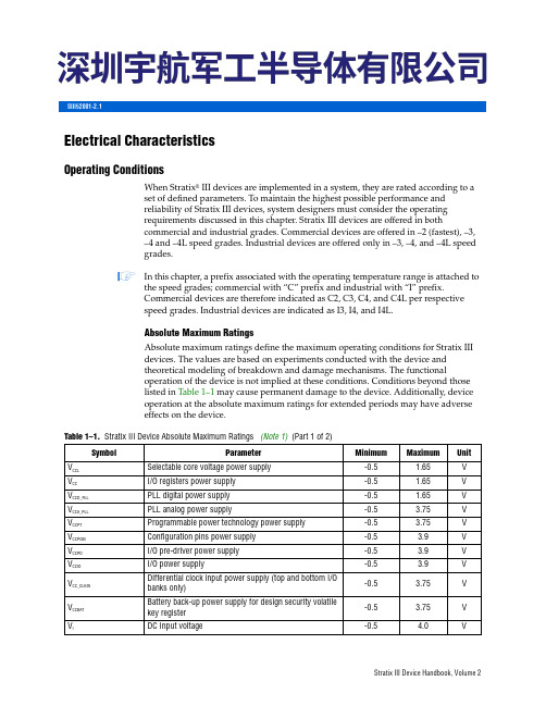
Electrical CharacteristicsOperating ConditionsWhen Stratix ®III devices are implemented in a system, they are rated according to a set of defined parameters. To maintain the highest possible performance and reliability of Stratix III devices, system designers must consider the operating requirements discussed in this chapter. Stratix III devices are offered in bothcommercial and industrial grades. Commercial devices are offered in –2 (fastest), –3, –4 and –4L speed grades. Industrial devices are offered only in –3, –4, and –4L speed grades.1In this chapter, a prefix associated with the operating temperature range is attached to the speed grades; commercial with “C” prefix and industrial with “I” prefix.Commercial devices are therefore indicated as C2, C3, C4, and C4L per respective speed grades. Industrial devices are indicated as I3, I4, and I4L.Absolute Maximum RatingsAbsolute maximum ratings define the maximum operating conditions for Stratix III devices. The values are based on experiments conducted with the device and theoretical modeling of breakdown and damage mechanisms. The functionaloperation of the device is not implied at these conditions. Conditions beyond those listed in Table 1–1 may cause permanent damage to the device. Additionally, device operation at the absolute maximum ratings for extended periods may have adverse effects on the device.Table 1–1.Stratix III Device Absolute Maximum Ratings (Note 1)(Part 1 of 2)SymbolParameterMinimum Maximum Unit V CCL Selectable core voltage power supply -0.5 1.65V V CC I/O registers power supply -0.5 1.65V V CCD_PLL PLL digital power supply -0.5 1.65V V CCA_PLL PLL analog power supply-0.5 3.75V V CCPT Programmable power technology power supply -0.5 3.75V V CCPGM Configuration pins power supply -0.5 3.9V V CCPD I/O pre-driver power supply -0.5 3.9V V CCIO I/O power supply-0.5 3.9V V CC_CLKIN Differential clock input power supply (top and bottom I/O banks only)-0.5 3.75V V CCBAT Battery back-up power supply for design security volatile key register -0.5 3.75V V IDC Input voltage-0.54.0VSIII52001-2.1Chapter 1:Stratix III Device Data Sheet: DC and Switching CharacteristicsSwitching CharacteristicsConfiguration and JTAG SpecificationsTable 1–23 lists the Stratix III Configuration Mode Specifications.Table 1–24 shows the JTAG timing parameters and values for Stratix III devices. Refer to figure for “HIGH-SPEED I/O Block” in “Glossary” for JTAG timing requirements.M144K (3), (5)Simple dual-port 2K × 64 (with ECC)01255210180180130195180120MHz Min Pulse Width (Clock High Time)——8001000110011001800100011001800ps Min Pulse Width (Clock Low Time )——50062569069011006256901100psNotes to Table 1–22:(1)Use a memory block clock that comes through global clock routing from an on-chip PLL set to 50% output duty cycle to achieve the maximum memory blockperformance. Use Quartus II software to report timing for this and other memory block clocking schemes.(2)The F max shown for M9K degrades 2 % when you use Error Detection CRC feature on the device, except for C4L speed grade with V CCL =0.9 V. For C4L speedgrade with V CCL =0.9V, there is no degradation in Fmax when Error Detection CRC feature is used.(3)The F max shown for M144K degrades 10 MHz when you use byte-enable support on M144K.(4)The F max is applicable when the COMPTABILITY option is turned ON.(5)The F max is applicable when the COMPTABILITY option is turned OFF. This option is turned ON by default in Quartus II software.(6)The F max for EP3SL200, EP3SE260, and EP3SL340 at C2 Speed Grade is 7% slower than the C2 values shown in the table.Table 1–22.Stratix III TriMatrix Memory Block Performance Specifications (Note 1)(Part 3 of 3)Memory Block TypeModeALUTsTriMatrixMemoryC2 (6)C3C4C4L I3I4I4L UnitV CCL = 1.1VV CCL = 1.1V V CCL = 1.1V V CCL = 1.1V V CCL = 0.9VV CCL =1.1VV CCL =1.1VV CCL =0.9VTable 1–23.Stratix III Configuration Mode Specifications (Note 1)Programming ModeDCLK F maxUnit Passive Serial 100MHz Fast Passive Parallel (2)100MHz Fast Active Serial (3)40MHzNotes to Table 1–23:(1)DCLK F max is restricted when Remote Update is enabled. For more information, refer to Remote Update Circuitry(ALTREMOTE_UPDATE) Megafunction User Guide .(2)Data rate must be 4× slower than the clock when decompression and/or encryption are used.(3)For more information about the minimum and typical DCLK F max value in Fast Active Serial configuration, refer tothe Serial Configuration Devices Data Sheet chapter in Cyclone Device Handbook .Table 1–24.Stratix III JTAG Timing Parameters and ValuesSymbol ParameterMin Max Unit t JCP TCK clock period 30—ns t JCH TCK clock high time 14—ns t JCLTCK clock low time 14—ns t JPSU (TDI)JTAG port setup time for TDI 1—ns t JPSU (TMS) JTAG port setup time for TMS 3—ns t JPH JTAG port hold time 5—ns t JPCO JTAG port clock to output—11 ns t JPZX JTAG port high impedance to valid output —14 ns t JPXZJTAG port valid output to high impedance—14nsSwitching CharacteristicsPeriphery PerformanceThis section describes periphery performance, including high-speed I/O and external memory interface.I/O performance supports several system interfacing, such as the LVDS high-speed I/O interface, external memory interface, and the PCI/PCI-X bus interface. Forexample, Stratix III devices I/O configured with voltage referenced I/O standards can achieve up to the stated system interfacing speed as indicated in “External Memory Interface Specifications” on page 1–25. General-purpose I/O standards such as 3.3, 3.0, 2.5, 1.8, or 1.5 LVTTL/LVCMOS are capable of typical 167 MHz and 1.2LVCMOS at 100MHz interfacing frequency with 10pF load.1Actual achievable frequency depends on design- and system-specific factors. You should perform HSPICE/IBIS simulations based on your specific design and system setup to determine the maximum achievable frequency in your system.High-Speed I/O SpecificationsRefer to the “Glossary” for definitions of high-speed timing specifications.Table 1–25 shows the high-speed I/O timing for Stratix III devices.Table 1–25.True & Emulated LVDS Specifications (Note 1), (2)(Part 1 of 3)SymbolConditionsC2C3, I3C4, I4C4L, I4LU n i tM i nT y pM a xM i nT y pM a xM i nT y pM a xM i nT y pM a xf HSCLK_in(input clock frequency)Clock boostfactor W = 1 to 40 (3)5—8005—7175—7175—717MHzf HSCLK_out(output clock frequency)—5—800 (7)5—717 (7)5—717 (7)5—717 (7)MHzTransmitterf HSDR (data rate)SERDES factor J = 3 to 10 (8)(4)—1600(4)—1250(4)—1250(4)—1250Mbps SERDES factor J = 2, Uses DDR Register (4)—(4)(4)—(4)(4)—(4)(4)—(4)MbpsSERDES factor J = 1, Uses SDR Register(4)—(4)(4)—(4)(4)—(4)(4)—(4)Mbps LVDS_E_3R -f HSDR (data rate)SERDES factor J = 4 to 10(4)—1100(4)—1100(4)—800(4)—800Mbps LVDS_E_1R -f HSDR (data rate)SERDES factor J = 4 to 10(4)—311(4)—200(4)—200(4)—200MbpsI/O Default Capacitive LoadingSee Table 1–40 for default capacitive loading of different I/O standards.MINI-LVDS_E_1R —100—120 2.325 2.325 1.02—0 1.1625MINI-LVDS_E_3R 120100—170 2.325 2.325 1.02—0 1.1625RSDS_E_1R —100—120 2.325 2.325 1.02—0 1.1625RSDS_E_3R120100—1702.3252.3251.02—1.1625Notes to Table 1–39:(1)Hyper transport is not supported by Stratix III.(2)LVPECL outputs are not supported by Stratix III.(3)Quartus timing conditions can be changed using the Advanced I/O Timing feature.(4)V CC is nominally 1.1 V less 50 mV (1.05 V).(5)Terminated I/O standards require an additional 30 mV IR drop on V CC (1.02 V).(6)Terminated I/O standards required an additional 50 mV IR drop on V CCIO and V CCPD .Table 1–39.Output Timing Measurement Methodology for Output Pins (Part 3 of 3)I/O StandardLoading and TerminationsMeasurementPoint R SR D R T R P V CCIO V CCPD V CC V TT C L (pF)V MEAS (v)Table 1–40.Default Loading of Different I/O Standards for Stratix III (Part 1 of 2)I/O StandardCapacitive LoadUnit 3.3-V LVTTL 0pF 3.3-V LVCMOS 0pF 3.0-V LVTTL 0pF 3.0-V LVCMOS 0pF 2.5-V LVTTL/LVCMOS 0pF 1.8-V LVTTL/LVCMOS 0pF 1.5-V LVTTL/LVCMOS 0pF 3.0-V PCI 10pF 3.0-V PCI-X 10pF SSTL-2 CLASS I 0pF SSTL-2 CLASS II 0pF SSTL-18 CLASS I 0pF SSTL-18 CLASS II 0pF 1.5-V HSTL CLASS I 0pF 1.5-V HSTL CLASS II 0pF 1.8-V HSTL CLASS I 0pF 1.8-V HSTL CLASS II 0pF 1.2-V HSTL0pF Differential SSTL-2 CLASS I 0pF Differential SSTL-2 CLASS II 0pF Differential SSTL-18 CLASS IpF。
pll的参数

PLL的参数介绍相位锁定环(Phase-Locked Loop,简称PLL)是一种广泛应用于通信、控制系统中的电路。
它可以将输入信号的相位和频率调整到与参考信号相匹配,实现信号的同步和频率转换。
PLL的参数设置对于系统的性能和稳定性至关重要。
本文将介绍PLL的参数及其影响,并提供一些常见的设置方法和技巧。
1. 相位检测器参数相位检测器(Phase Detector,简称PD)用于比较输入信号和参考信号的相位差,并产生控制信号。
常见的相位检测器包括边沿触发相位检测器(Edge-Triggered Phase Detector,简称ETPD)和恒幅相位检测器(Amplitude-Insensitive Phase Detector,简称AIPD)。
以下是一些常见的相位检测器参数:1.1 灵敏度相位检测器的灵敏度决定了它对相位差的响应程度。
灵敏度越高,相位检测器对相位差的响应越快。
然而,过高的灵敏度可能导致相位锁定环的震荡和不稳定。
因此,在实际应用中需要根据系统的要求和稳定性进行合适的调整。
1.2 噪声抑制比噪声抑制比是相位检测器抑制输入信号中的噪声的能力。
较高的噪声抑制比可以提高系统的抗噪性能。
一些常见的提高噪声抑制比的方法包括使用滤波器和引入环路滤波器。
2. 频率控制电压参数频率控制电压(Voltage Controlled Oscillator,简称VCO)是PLL中的一个关键部件,它通过控制输入信号的频率来实现与参考信号的同步。
以下是一些常见的VCO参数:2.1 频率范围频率范围是VCO可以工作的频率范围。
在选择VCO时,需要根据系统的要求和应用场景来确定合适的频率范围。
2.2 频率线性度频率线性度是指VCO输出频率与控制电压之间的线性关系。
较好的频率线性度可以提高PLL的性能和稳定性。
3. 倍频器参数倍频器(Multiplier)用于将VCO输出的频率倍增到所需的频率。
以下是一些常见的倍频器参数:3.1 倍频比倍频比是指倍频器将输入频率乘以的倍数。
电动车维修技巧附录 电动自行车常用件资料

400V
10A
6
LIN-B
为驱动逆变桥B相低压下桥臂功率MOSFET管的信号输入端,与六路控制脉冲形成电路中输出的B相低压下桥臂功率管驱动输出信号端相连接。
7
LIN-C
为驱动逆变桥C相低压下桥臂功率MOSFET管的信号输入端,与六路控制脉冲形成电路中输出的C相低压下桥臂功率管驱动输出信号端相连接。
8
/FAULT
过电流、直通短路及过电压、欠电压保护输出端,该端提供一个过电流、直通或过电压、欠电压保护的指示信号,应用中,当IR2130保护动作时输出低电平,接指示用发光二极管或用户系统封锁端。
18
CT/RT
SP C
CF
CF
ID
CA-
GND
VCC
VC
振荡器定时电容、电阻
误差放大器同相输入
误差放大器反相输入
误差放大器输出
故障信号输出指示
电流检测反相输入
地
集成电路电源
下桥输出驱动电路电源
MC33035无刷电动机驱动集成电路
19
20
21
22
23
24
CB
BB
AB
60°/120°
BRAKE
CT
C相下臂驱动输出
8
9
BT
AT
FOR/REV
(A)
(B)
(C)
START/STOP
VREF
CA+
B相上臂驱动输出
输出A相上臂驱动
正反转控制
A相霍耳信号输入
B相霍耳信号输入
C相霍耳信号输入
启动/停止控制,高电平启动,低电平停车
5V基准电压输出
电流检测输入
PLL
5,16、Analog Power Supplies. These pins range from 3.15 V to 3.45 V. Connect decoupling capacitors to the analog ground plane as close to these pins as possible. AVDD must have the same value as DVDD.
Integrated rms jitter (1 kHz to 20 MHz): 97 fs for 6 GHz output
Fractional-N synthesizer and integer N synthesizer
Pin compatible to the ADF5355
High resolution, 52-bit modulus
1、Serial Clock Input. Data is clocked into the 32-bit shift register on the CLK rising edge. This input is a high impedance CMOS input.
串行时钟输入 数据在CLK上升沿被计入32位移位寄存器。 该输入是高阻抗CMOS输入。
集成RMS抖动(1 kHz至20 MHz):6 GHz输出为97 fs
小数N分频频率合成器和整数N分频频率合成器
与ADF5355引脚兼容
高分辨率、52位模数
工作频率高达125 MHz的鉴频鉴相器(PFD)
参考输入频率达600 MHz
OX2140中文资料
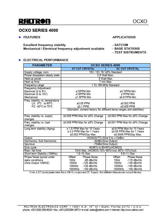
OCXO SERIES 4000n FEATURES APPLICATIONS Excellent frequency stability - SATCOMMechanical / Electrical frequency adjustment available - BASE STATIONS- TEST INSTRUMENTSn ELECTRICAL PERFORMANCEPARAMETER OCXO SERIES 4000AT CUT CRYSTAL SC CUT CRYSTAL Supply voltage, nom. 15V, 12V, 5V ±5% StandardPower dissipation steady state 2.5 Watt Max.Heat up power 5 Watt MaxHeat up time. 7 min MaxFrequency range 1 To 160 MHz StandardFrequency Adjustment:Electrical (0 to 5V) Electrical (0 to 10V) Mechanical ±10PPM Min±15PPM Min±1.5PPM Min±0.7PPM Min±1PPM Min±0.6 PPM Min±0.05 PPM±0.1 PPM±0.002 PPM±0.005 PPMFreq. stability vs. temperatureLX: 0°C to 60°CFZ: -30°C to 70°C(Standard, contact factory for different temp ranges and stabilities) Freq. stability vs. supplychanges±0.005 PPM Max for ±5% Change ±0.002 PPM Max for ±5% ChangeFreq. stability vs. loadchanges±0.005 PPM Max for ±5% Change ±0.001 PPM Max for ±5% ChangeLong term stability (Aging) ± 1.5 PPM Max for 10 Years± 0.3 PPM Max for 1 Years±0.002 PPM/Day Max. ±0.6 PPM Max for 10 Years ±0.05 PPM Max for 1 Years ±0.0005 PPM/Day Max.Output HCMOS/TTL/Sine 0 to +13dBm Harmonics, Sub Harmonics -30dBc(Sine Output)Spurious -75dBc(Sine Output)Duty cycle 40/60% to 60/40%(HCMOS)Rise / fall time 10nS Max. (HCMOS,10%~90%Vout, 90%~10%Vout) Short term Stability (10MHz) 1 E-10 /Sec 5 E-11 /SecPhase Noise typical under static conditions(Sine Output 10MHZ) Offset Phase Noise10Hz -95 dBc/Hz100Hz -125 dBc/Hz1000Hz -135 dBc/Hz10000Hz -150 dBc/HzOffset Phase Noise10Hz -115 dBc/Hz100Hz -135 dBc/Hz1000Hz -145 dBc/Hz10000Hz -150 dBc/HzNote: All Typical parameters for a 10MHz output and 5V Supply, for different frequencies consult factoryn HOW TO ORDER (PART NUMBER)Prefix Output Type Cut TypeSeries Revision Temperature Range Stability FrequencySupply Voltage OX1:TTL 2:HCMOS 3:ACMOS 4:LVCMOS 5:100K ECL 6:SINE 7:10K ECL 8: PECL 9:CUSTOM0:AT (No Vcontrol ) 1: SC (No Vcontrol ) 2: AT (Mechanical Adj) 3: SC (Mechanical Adj) 4: AT (Elect Vcontrol) 5: SC (Elect Vcontrol) 6: AT (Mech & Elect.) 7: SC (Mech & Elect.)4X:4000 40:Height=1”/25.4mm41:Height=2”/50.8mm42:Height=4”/101.6mm44~49:Odd HeightAFirst letter Lowest Temperature,Second letter Highest Temperature: From A=-55°C to Z=+70°C, Then: 1=+75°C, 2=+80°C, 3=+85°C… in 5°C steps Example: LZ: +0°C to +70°C LX: +0°C to +60°C FZ: -30°C to +70°C D3: -40°C to +85°CValue x10E-2 in PPMExample 28=0.28PPM 10= 0.1PPMIn MHZ5: 5V 12; 12V 15; 15V。
- 1、下载文档前请自行甄别文档内容的完整性,平台不提供额外的编辑、内容补充、找答案等附加服务。
- 2、"仅部分预览"的文档,不可在线预览部分如存在完整性等问题,可反馈申请退款(可完整预览的文档不适用该条件!)。
- 3、如文档侵犯您的权益,请联系客服反馈,我们会尽快为您处理(人工客服工作时间:9:00-18:30)。
PLL Product Specification
Model:PLL350-2140(Y) Rev:P4 Date:9/1/2006 Customer:
SIRENZA
MICRODEVICES, INC.
AppNote:
113, Opt. 207000
Operating Temperature Range:
(-35 ° to 85 ° C)
RoHS Compliant
To order models as RoHS Compliant add "Y" suffix to base model number.
Parameter
Min Typ Max Units X Remarks
Frequency Range - 2110
21402170MHz X Step Size -
200kHz X Settling Time - To within 1 kHz 2
4mSec Output Power - 03
6
dBm
X
Output Phase Noise:
1kHz -79-73dBc/Hz 100 kHz -122-116dBc/Hz 800 kHz
-140
-134
dBc/Hz
X
Power Supply:
VCO 4.755 5.25Volts PLL IC
2.9
3
3.1
Volts
Supply Current:
VCO 3550mA X PLL IC
1015mA Spurious Product - 200 kHz -85-70dBc X
Reference Feedthrough - -85
-70
dBc
Harmonic Suppression:
2nd Harmonic -25-15dBc X 3rd Harmonic
-30
-20
dBc
X
Ref Osc Signal:
Frequency 10
MHz Amplitude
0.4
3
Vp-p Phase Noise - 1 kHz -145dBc/Hz Input Impedance
100k
Output Impedance -
50
Package Information
Package Type:
PLL350
(0.8 x 0.582 x 0.154 inches
)
Drawing Number: 61054
Comments
X Indicates parameter to be tested 100% in production
Performance tests and ratings for Sirenza Microdevices'products were performed internally by Sirenza and measured using specific computer systems and/or components and reflect the approximate performance of the the products as measured by those tests.Any difference in circuit implementation,test software,or test equipment may affect actual performance.The information provided herein is believed to be reliable at press time and Sirenza
Microdevices assumes no responsibility for the use of this information.All such use shall be entirely at the user's own risk.Prices and specifications for Sirenza Microdevices'products are subject to change without notice.Buyers should consult Sirenza Microdevices'standard terms and conditions of sale for Sirenza's limited warranty with regard to its products.These products may be patented or include patented technology.No patent rights or licenses to any of the circuits described herein are implied or granted to any third party.Sirenza Microdevices does not authorize or warrant any product for use in life-support devices and/or systems.
Sirenza Microdevices,Inc.。
